


®
Product questions or problems?
-331-
Customer Care Hot Line
Get answers to questions, troubleshoot problems,
order parts, or schedule repair service.
Para respuestas a preguntas o problemas, y ordenar
piezas o pedir servicio para la reparaci6n de su equipo.
To help us help you, register your product at www.craftsman.comlregistration
Para poderte ayudar mejor, registratu producto en www.craftsman.com!registration
Join the Craftsman Club today!
Operator's Manual
12 Amp
lectric
Lawn dger
Model No.
172.796570
®
c@s
Intertek
3025736
www, craftsman,com/signup
Receive exclusive member benefits including special pricing and offers,
project sharing, expert advice, and SHOP YOUR WAY REWARDS!
Como miembro exclusivo, recibe diversos beneficios como ofertas, precios especiales, proyectos
nuevos, consejos de expertos y nuestro programa de puntos SHOP YOUR WAY REWARDS!
® Registered Trademark / Trademark of KCD IP, LLC in the United States, or Sears Brands, LLC in other countries
® Marca Registrada / Marca de Fabrica de KCD _P, LLC en Estados Unidos, o Sears Brands, LLC in otros paises
TM
TM
CAUTION:
Read, understand and follow all Safety
Rules and Operating Instructions in this
Manual before using this product.
Sears Brands Management Corporation,
Hoffman Estates, IL 60179 U.S.A.
www.craftsman.com
• WARRANTY
• SAFETY
• ASSEMBLY
• OPERATION
• MAINTENANCE
• PARTS LIST
Warranty............................................................................................ Page 2
Safety Symbols ................................................................................... Page 3
Safety Instructions ................................................................................ Pages 4 - 9
Unpacking........................................................................................ Page 10
Description ......................................................................................... Pages 11 - 12
Assembly and Adjustments .................................................................. Pages 13 - 16
Operation.............................................................................................. Pages 17 - 22
Maintenance......................................................................................... Pages 23 - 24
Parts List............................................................................................. Pages 25 - 27
The purpose of safety symbols is to attract your attention to possible dangers. The
safety symbols, and the explanations with them, deserve your careful attention and
understanding. The symbol warnings DO NOT by themselves eliminate any danger.
The instructions and warnings they give are no substitutes for proper accident
prevention measures.
WARNING: BE SURE to read and understand all safety instructions in this
manual, including all safety alert symbols such as "DANGER", "WARNING"
and "CAUTION", BEFORE using this tool. Failure to follow all instructions listed
below may result in electric shock, fire and/or serious personal injury.
SYMBOL MEANING
CRAFTSMAN LiMiTED WARRANTY
FOR TWO YEARS from the date of sale, this product iswarranted against
defects in material or workmanship.
WITH PROOF OF SALE, a defective product will be replaced free of charge.
For warranty details to obtain free replacement, visit the web page:
www.craftsman, corn/warranty
This warranty does not cover the blade, which is an expendable part
that can wear out from normal use within the warranty period.
This warranty gives you specific legal rights, and you may also have
other rights which vary from state to state.
Sears Brands Management Corporation, Hoffman Estates, IL 60179
contains chemicals known to the State of California to cause cancer and birth
i _ WARNING: Some dust created by using lawn and garden power tools
defects or other reproductive harm.
SAVE THESE iNSTRUCTiONS!
READ ALL iNSTRUCTiONS!
i
Z,_ SAFETY ALERT SYMBOL: Indicates DANGER,WARNING,OR
[ z_WARNING i
DAMAGE PREVENTION AND iNFORMATiON MESSAGES
These inform user of important information and/or instructions that could lead to
equipment or other property damage if not followed. Each message is preceded by the word
"NOTE:" as in the example below:
i
CAUTION. May be used in conjunction with other syrnbols or pictographs.
Failure to obey this safety warning WiLL result in death or
serious injury to yourself or to others. Always follow the
safety precautions to reduce the risk of fire, electric shock
and personal injury.
Failure to obey this safety warning CAN result in death or
serious injury to yourself or to others. Always follow the
safety precautions to reduce the risk of fire, electric shock
and personal injury.
Z_ CAUTION I injury to yourself or others or property damage. Always
NOTE: Equipment and/or property damage may result if these instructions |
are not followed.
WEAR YOUR
i Failure to obey this safety warning MAY result in personal
follow the safety precautions to reduce the risk of fire,
electric shock and personal injury.
z_WARNING: The operation of any edger can result in
foreign objects being thrown into your eyes, which can
result in severe eye damage. Before beginning power tool
operation, ALWAYS wear safety goggles or safety glasses
with side shields and a full-face shield when needed. We
recommend a Wide Vision Safety Mask for use over
eyeglasses or standard safety glasses with side shields,
available at Sears Stores or other Craftsman Outlets.
i
J
2 3
Z_WARNING: if correctly used, this electric Edger is an easy to handle and
efficient tool; if used improperly or without the due precautions it could become a
dangerous tool. For pleasant and safe work, ALWAYS strictly comply with the safety
rules that are contained in this manual.
Z_ WARNING: BE SURE to read and understand all instructions in this manual
before using this electric Edger. Failure to follow all instructions listed below may
result in electric shock, fire and/or serious personal injury.
z_ WARNING: To avoid mistakes that could cause serious injury, DO NOT plug
in this tool until the following instructions have been read and understood.
WORK AREA SAFETY
1. ALWAYS avoid dangerous conditions. DO NOT use in wet or damp areas or
expose to rain.
2. DO NOT operate in the presence of flammable liquids, gases, or dust. Electric
tools create sparks which may ignite dust or fumes.
3. ALWAYS keep bystanders and visitors at a safe distance while operating
an Edger. NEVER allow children near the tool. Flying objects can injure anyone
in the area.
4. CHILDPROOF your tools with padlocks and master switches. Lock tools away when
not in use. This Edger is not a toy.
5. DO NOT use the Edger without adequate lighting. ALWAYS make sure that you can
see what you are edging.
6. BEFORE using the Edger, remove any stones, sticks, debris or objects that could
be entangled in or thrown by the Edger.
PERSONALSAFETY
BEING THROWN, which can result in personal injury or property damage.
I z_ WARNING: The operation of any Edger can result in FOREIGN OBJECTS
ALWAYS use proper safety equipment.
1. KNOW your tool. Read the operator's manual carefully. Learn the electric Edger's
applications and limitations, as well as the specific potential hazards related to this tool.
2.STAY ALERT, watch what you are doing and use common sense when operating this tool.
3. DO NOT use tool while tired or under the influence of drugs, alcohol or medication.
A moment of inattentionwhile operating this tool may result inserious personal injury.
4. DRESS properly. Wear rubber gloves and substantial rubber soled footwear when
working outdoors. DO NOT operate lawn and garden tools when barefoot or wearing
open sandals. Wear long pants and long sleeves to protect your legs and arms.
Edgers can pick up objects such as rocks and send them flying at fast speeds.
DO NOT wear loose clothing or jewelry. Keep your hair, clothing, and gloves away
form moving parts. Loose clothing or long hair can be caught in moving parts.
1
1
PERSONAL SAFETY cont.
5. USE SAFETY EQUIPMENT. Always wear safety goggles or safety glasses with side
shields or full face shield, proper work shoes with rubber non-slip soles, heavy-duty
non-slip rubber gloves and dust mask or respirator and hearing protection. Hard
hat should be used for appropriate conditions.
6. DO NOT overreach. Keep proper footing and balance at all times. Proper footing and
balance enables better control of the tool in unexpected situations.
TOOL USE AND CARE SAFETY
operating this tool. Failure to follow all instructions listed below may result in
z_ WARNING: BE SURE to read and understand all instructions before
electric shock, fire and/or serious personal injury.
1. DO NOT use the tool if switch does not turn it "On" or "Off". Any tool that cannot be
controlled with the switch is dangerous and must be repaired.
2. DISCONNECT the plug from the power source before making any adjustments,
changing accessories, or storing the tool. Such preventive safety measures reduce the
risk of starting the tool accidentally.
3. STORE idle tools out of the reach of children and other untrained persons. Children
MUST NOT operate the tool. Tools are dangerous in the hands of untrained users.
4. MAINTAIN tools with care. ALWAYS keep cutting tools clean and in good working order.
5. CHECK for misalignment or binding of moving parts, breakage of parts, and any other
condition that may affect the tool's operation. If damaged, have the tool serviced
before using. Many accidents are caused by poorly maintained tools.
6. USE ONLY cutting blades that are recommended for this Edger. Blades that may be
suitable for one Edger may become hazardous when used on another Edger.
ELECTRICAL SAFETY
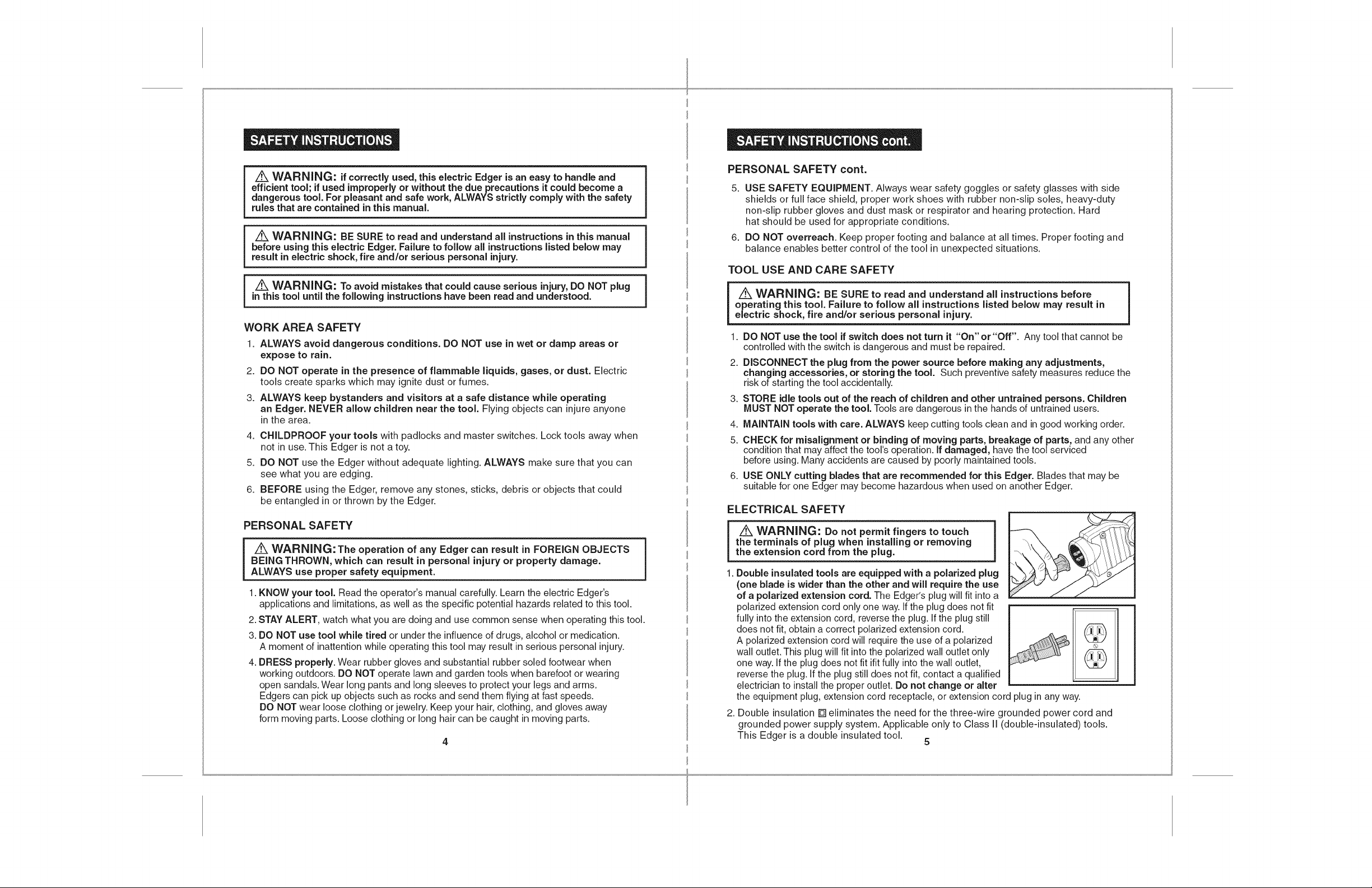
z_ WARNING: Do not permit fingers to touch ]
the terminals of plug when installing or removing
the extension cord from the plug.
. Double insulated tools are equipped with a polarized plug
(one blade is wider than the other and will require the use
of a polarized extension cord. The Edger's plug will fit into a
polarized extension cord only one way. If the plug does not fit
fully intothe extension cord, reverse the plug. If the plug still
does not fit, obtain a correct polarized extension cord.
A polarized extension cord will require the use of a polarized
wall outlet. This plug will fit intothe polarized wall outlet only
one way.If the plug does not fit ifitfully intothe wall outlet,
reverse the plug. If the plug still does not fit, contact a qualified
electrician to installthe proper outlet. Do not change or alter
the equipment plug, extension cord receptacle, or extension cord plug inany way.
2. Double insulation [] eliminates the need for the three-wire grounded power cord and
grounded power supply system. Applicable only to Class II (double-insulated) tools.
This Edger is a double insulated tool.
5
1
ELECTRICAL SAFETY cont.
EXTENSION CORDS cont.
A WARNING: GFCJ (Ground Fault Circuit Interrupter) protection should be
provided on aJl circuits or outlets to be used for electric lawn and garden power
tools. Receptacles are available having built-in GFCl protection and should be
used for this measure of protection.
Z_ WARNING: Double insulation DOES NOT take the place of normal safety
precautions when operating this tool.
3. BEFORE plugging in the tool, BE SURE that the outlet voltage supplied is within
the voltage marked on the tool's data plate. DO NOT use "AC only" rated tools with a DC
power supply.
4. DO NOT expose tools to rain or wet conditions or use electric tools in wet or damp
locations. Water entering an electric tool will increase the risk of electric shock.
5. If operating an electric tool in damp locations is unavoidable, ALWAYS USE a
Ground Fault Circuit interrupter to supply power to your tool. ALWAYS WEAR
electrician's rubber gloves and footwear in damp conditions.
6. When operating a power tool outside, ALWAYS use an outdoor extension cord marked
"W-A" or "W". these cords are rated for outdoor use and reduce the risk of electric shock.
7. iNSPECT tool cords for damage. Have damaged tool cords repaired at a Sears Service
Center. BE SURE to stay constantly aware of the cord location and keep it well away
from the cutting blade.
8. DO NOT abuse the extension cord. NEVER use the cord to carry the tool by or to
pull the plug from the outlet. Keep cord away from heat, oil, sharp edges or moving parts.
Replace damaged cords immediately. Damaged cords increase the risk of electric shock.
EXTENSION CORDS
Use a proper extension cord. ONLY use cords listed by Underwriters Laboratories (UL).
Other extension cords can cause a drop in line voltage, resulting ina loss of power
and overheating of tool.
For this tool an AWG (American Wire Gauge) size of a least 14-gauge is recommended
for an extension cord of 25-ft. or less in length. Use 12-gauge for an extension cord
of 50-ft. Extension cords 100=ft. or longer are not recommended.
Remember, a smaller wire gauge size has greater capacity than a larger number
(14-gauge wire has more capacity than 16-gauge wire; 12-gauge wire has more capacity
than 14-gauge). When indoubt use the smaller number.
When operating a power tool outdoors, use an outdoor extension cord marked "W-A" or "W'.
These cords are rated for outdoor use and reduce the risk of electric shock.
Z_ CAUTION: Keep the extension cord clear of the work area. Position the
cord so that it will not get caught on bushes, hedges, tree trunks, lawnmowers
or other obstructions while you are working with the Edger.
!
1
J
immediately. Never use tool with a damaged cord since touching the damaged
i Z_ WARNING: Check extension cords before each use. If damaged replace
area could cause electrical shock, resulting in serious injury.
SAFETY SYMBOLS FOR YOUR TOOL
The label on your tool may include the following symbols.
V....................................................................... Volts
A...................................................................... Amps
Hz.................................................................... Hertz
W..................................................................... Watts
min .................................................................. Minutes
,-,,.,.................................................................... Alternating current
................................................................... Direct current
no .................................................................... No-load speed
[] .................................................................... Class II construction
.../min .............................................................. Revolutions or Strokes per minute
z_ .................................................................... Indicates danger, warning or caution.
SERVICE SAFETY
1. If any part of this Edger is missing or should break, bend, or fail in any way;
or should any electrical component fail to perform properly: SHUT OFF the
power switch and remove the power cord from the Edger and have the missing,
damaged or failed parts replaced BEFORE resuming operation.
2. Tool service should be performed at a Sears Parts and Repair Center or other
qualified service dealer. Service or maintenance performed by unqualified personnel
could result in a risk of injury.
3. When servicing a tool, use only identical replacement parts. Follow instructions
in the maintenance section of this manual. Use of unauthorized parts or failure to
follow maintenance instructions may create a risk of electric shock or injury.
It means attention! Your safety is involved.
SAFETY RULES FOR ELECTRIC EDGERS
1. KNOW your electric Edger. Read operator's manual carefully. Learn the
applications and limitations, as well as the specific potential hazards related to this tool.
Following this rule will reduce the risk of electric shock, fire or serious injury.
2. DO NOT use the Edger without adequate lighting. ALWAYS make sure that you can
see what you are edging.
3. Use Edger ONLY when grass and weeds are dry.
4. ALWAYS stand to the left of the Handle. Any debris thrown by the Edger would be
coming from the Blade Guard area on the right of the Edger.
5. ALWAYS remove objects such as stones, sticks, and debris from the edging
path that could become entangled in, or thrown by the Edger.
6. To reduce the risk of rebound (ricochet), work going away from any nearby solid object
such as a wall, steps, large stone, tree, etc. Use care when working near solid objects
or into the wind. If necessary, do edging in those areas by hand.
6 7
SAFETY RULES FOR ELECTRIC EDGERS cont.
7. ALWAYS hold the Edger with both hands on the Handle and NEVER reach near or
under the Blade Guard.
8. AVOID accidental starting. DO NOT carry a plugged in Edger with your finger
on the Power Switch Lever.
9. DO NOT carry the Edger by the extension cord or pull the cord to disconnect it from the
receptacle. Keep cord away from heat, oil and sharp edges.
10. DO NOT FORCE the Edger. Do not try to cut more than what the Edger is designed
for. It will do a better job with less chance of injury when used at the rate for which it is
designed.
11. MAINTAIN the Edger with care. ALWAYS inspectthe extension cord and replace ifdamaged.
12. KEEP the Handle dry, clean and free of oil and grease. Use a clean cloth when cleaning.
DO NOT use solvents, brake fluids, gasoline, or other petroleum products to clean the
Edger. They can damage plastic parts.
13. NEVER, for any reason, touch the cutting blade or other moving parts during use.
14. KEEP Blade Guard in place and in good working order. Keep Guard positioned over blade.
Keep hands and feet away from cutting blade.
15. ALWAYS store the Edger indoors when not in use. It should be stored in a dry place,
high up or locked ina place that is out of the reach of children.
16. ALWAYS use only the blade provided with this Edger or sold specifically for this
Edger. Use of any other blades may create a hazardous situation.
17. ALWAYS keep ventilation openings clear of debris.
18. KEEP ALL BYSTANDERS AWAY at a safe distance from the work area, especially children.
Make sure that persons and pets are at least 100 feet away.
unplugged Edger and the Edger has come to a complete stop.
A WARNING: NEVER reach under the Edger (blade area) until you have
The Edger's blade will continue to rotate for a few seconds after it is switched off.
ADDiTiONAL RULES FOR SAFE OPERATION
follow all instructions listed below may result in electric shock, fire and/or
i z_ WARNING: BE SURE to read and understand all instructions. Failure to
serious personal injury.
1.
ALWAYS wear safety glasses or eye shields when using this Edger.
Everyday eyeglasses have only impact-resistant lenses; they are NOT safety glasses.
2.
PROTECT your lungs. Wear a face mask, dust mask or respirator if the operation is dusty.
3.
PROTECT your hearing. Wear appropriate personal hearing protection during use.
Under some conditions noise from this product may contribute to hearing loss.
4.
ALL VISITORS AND BYSTANDERS MUST wear the same safety equipment that the
operator of the tool wears.
5.
ALWAYS check the tool for damaged parts. Check for misalignment or binding of moving
parts, breakage of parts, and any other condition that may affect the tool's operation. Before
further use of the tool, a guard or other part that is damaged should be carefully checked to
determine if it will operate properly and perform its intended function. A guard or other part
that is damaged should be properly repaired or replaced at a Sears or other qualified
service dealer.
z_ WARNING: Some dust particles created by lawn and garden tools
contain chemicals known to cause cancer, birth defects or other reproductive
harm. Some examples of these chemicals are:
• Compounds in fertilizers, herbicides, pesticides, and insecticides.
• Arsenic and chromium from chemically treated lumber.
Your risk from these exposures varies, depending upon how often you do this
type of work.To reduce your exposure to these chemicals:
• Work in a well=ventilated area
• Work with approved safety equipment, such as those dust masks
that are specially designed to filter out microscopic particles.
8 9
6. SAVE THESE INSTRUCTIONS. Refer to them frequently and use them
to instruct others who may use this tool. If someone borrows this tool, make sure
they have these instructions also.
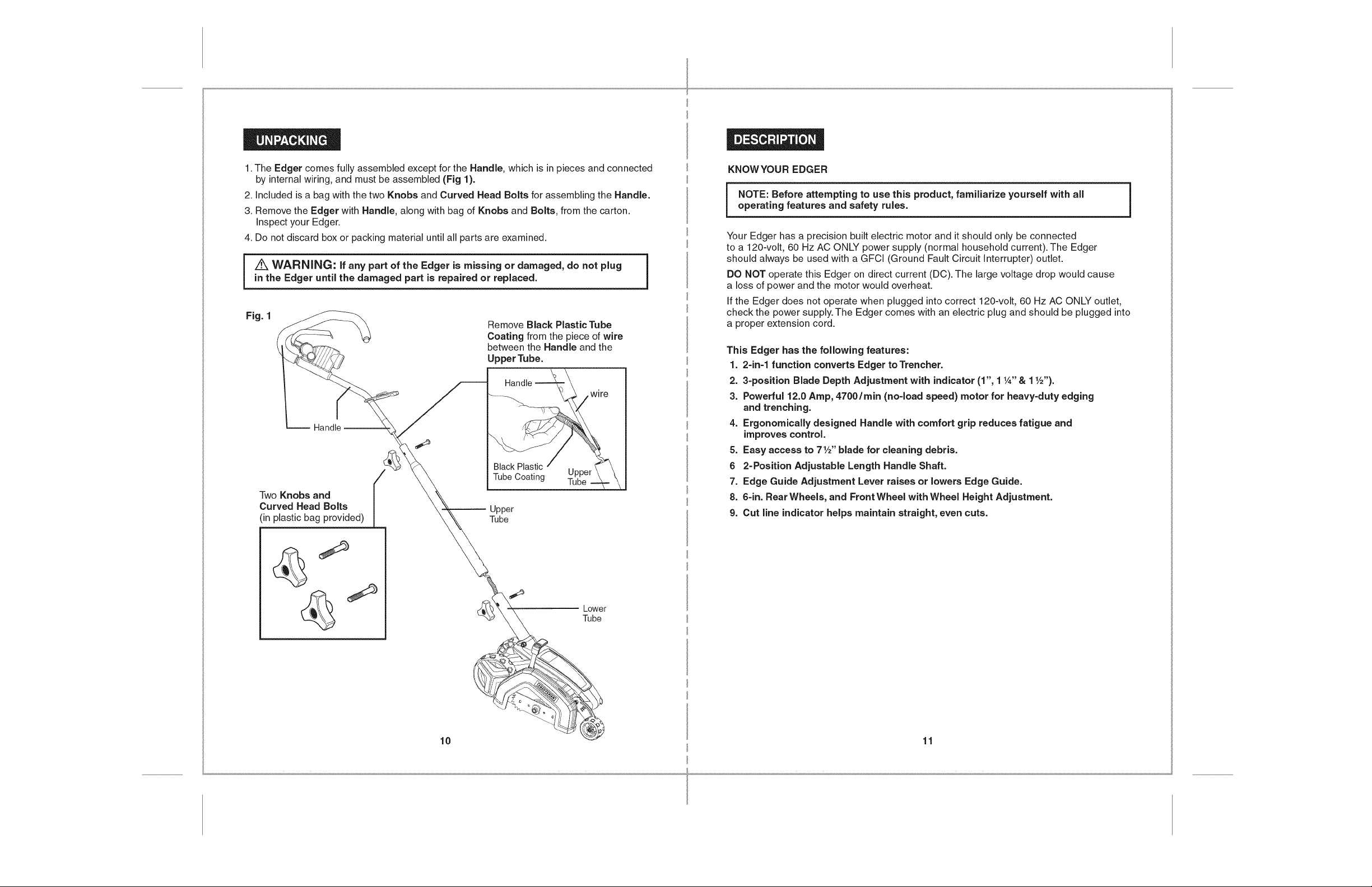
1.TheEdgercomesfullyassembledexceptfortheHandle,whichisinpiecesandconnected
byinternalwiring,andmustbeassembled(Fig1).
2.Included is a bag with the two Knobs and Curved Head Bolts for assembling the Handle.
3. Remove the Edger with Handle, along with bag of Knobs and Bolts, from the carton.
Inspect your Edger.
4. Do not discard box or packing material until all parts are examined.
z_ WARNING: if any part of the Edger is missing or damaged, do not plug
in the Edger until the damaged part is repaired or replaced. 1
Remove Black Plastic Tube
Coating from the piece of wire
between the Handle and the
UpperTube.
Handle
Black Plastic
Two Knobs and
Curved Head Bolts
(in plastic bag provided)
Tube Coating Upper
Upper
Tube
Tube
KNOWYOUR EDGER
NOTE: Before attempting to use this product, familiarize yourself with all i
operating features and safety rules.
Your Edger has a precision built electric motor and it should only be connected
to a 120-volt, 60 Hz AC ONLY power supply (normal household current). The Edger
should always be used with a GFCI (Ground Fault Circuit Interrupter) outlet.
DO NOT operate this Edger on direct current (DC). The large voltage drop would cause
a loss of power and the motor would overheat.
If the Edger does not operate when plugged into correct 120-volt, 60 Hz AC ONLY outlet,
check the power supply. The Edger comes with an electric plug and should be plugged into
a proper extension cord.
This Edger has the following features:
1. 2=in=l function converts Edger to Trencher.
2. 3=position Blade Depth Adjustment with indicator (1", 1 1A"& 1V2").
3. Powerful 12.0 Amp, 4700/rain (no=load speed) motor for heavy=duty edging
and trenching.
4. Ergonomically designed Handle with comfort grip reduces fatigue and
improves control.
5. Easy access to 7W' blade for cleaning debris.
6 2=Position Adjustable Length Handle Shaft.
7. Edge Guide Adjustment Lever raises or lowers Edge Guide.
8. 6=in. Rear Wheels, and Front Wheel with Wheel Height Adjustment.
9. Cut line indicator helps maintain straight, even cuts.
1
10
Lower
Tube
11
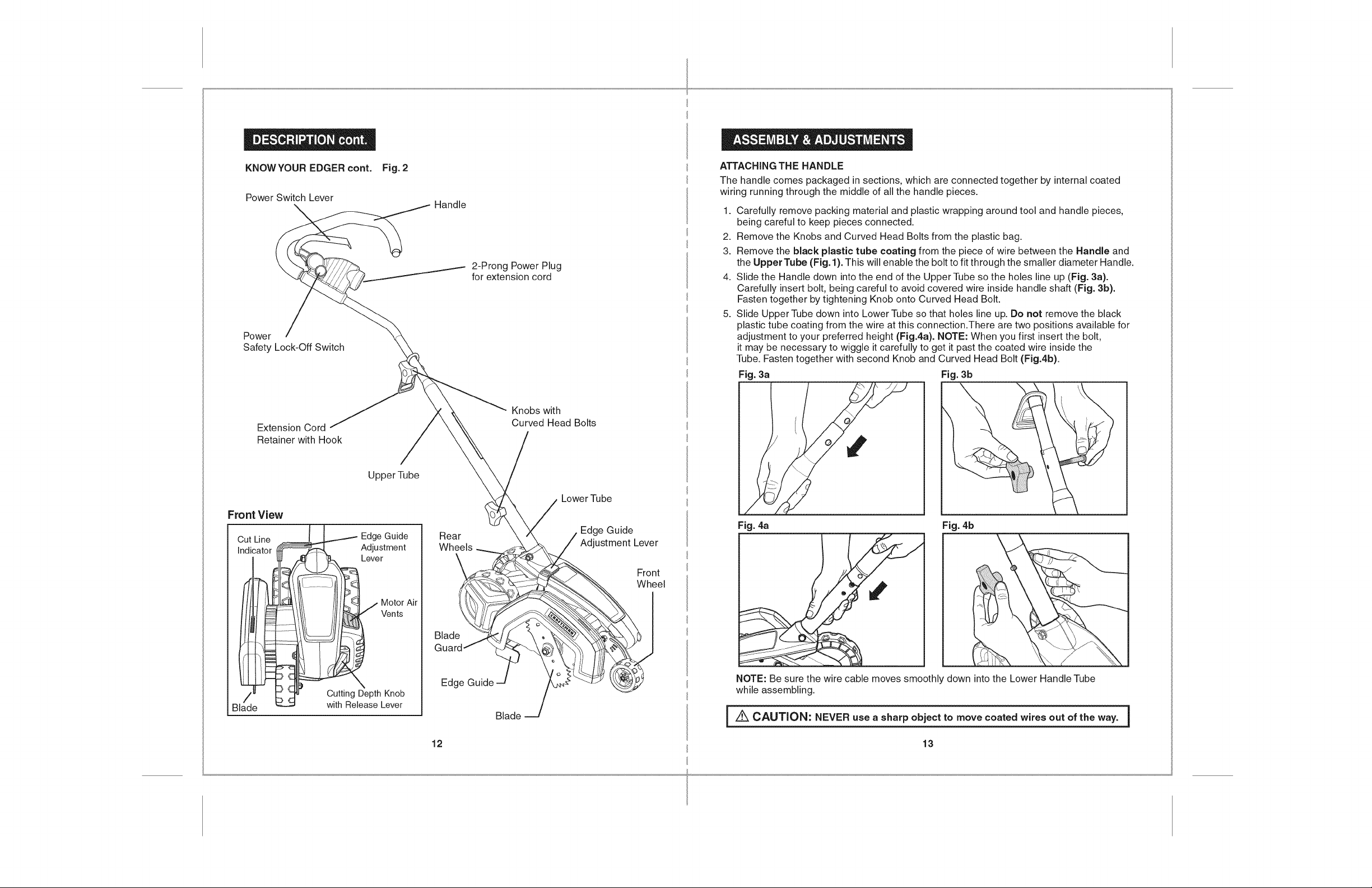
KNOWYOUREDGERcont. Fig. 2
Power Switch Lever
Power
Safety Lock-Off Switch
Handle
2-Prong Power Plug
for extension cord
ATTACHING THE HANDLE
The handle comes packaged in sections, which are connected together by internal coated
wiring running through the middle of all the handle pieces.
1. Carefully remove packing material and plastic wrapping around tool and handle pieces,
being careful to keep pieces connected.
2. Remove the Knobs and Curved Head Bolts from the plastic bag.
3. Remove the black plastic tube coating from the piece of wire between the Handle and
the Upper Tube (Fig. 1).This will enable the bolt to fit through the smaller diameter Handle.
4. Slide the Handle down into the end of the Upper Tube so the holes line up (Fig. 3a).
Carefully insert bolt, being careful to avoid covered wire inside handle shaft (Fig. 3b).
Fasten together by tightening Knob onto Curved Head Bolt.
5. Slide Upper Tube down into Lower Tube so that holes line up. Do not remove the black
plastic tube coating from the wire at this connection.There are two positions available for
adjustment to your preferred height (Fig.4a). NOTE: When you first insert the bolt,
it may be necessary to wiggle it carefully to get it past the coated wire inside the
Tube. Fasten together with second Knob and Curved Head Bolt (Fig.4b).
Fig. 3a Fig. 3b
\
Extension Cord
Retainer with Hook
Front View
Cut Line
Indicator
Blade
Upper Tube
Edge Guide
Adjustment
Lever
MotorAir
J Vents
k
Cutting Depth Knob
with Release Lever
Rear
Wheels
Blade
Edge Guide
Knobs with
Curved Head Bolts
Blade
Lower Tube
Edge Guide
Adjustment Lever
\
Fig. 4a Fig. 4b
Front
Wheel
NOTE: Be sure the wire cable moves smoothly down into the Lower Handle Tube
while assembling.
i Z_ CAUTION: NEVER use a sharp object to move coated wires out of the way.
12
13
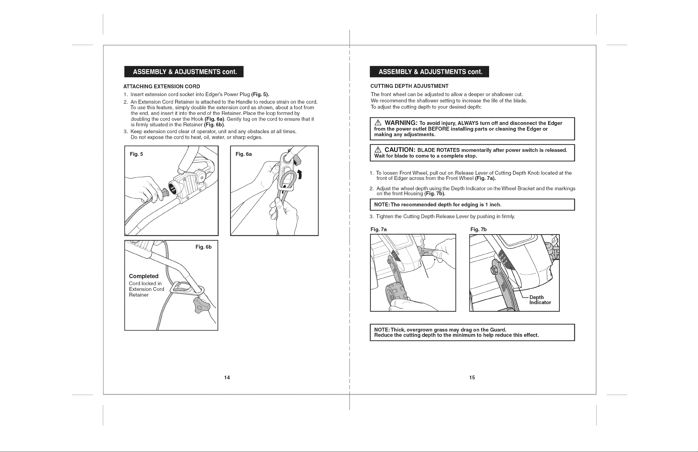
ATTACHING EXTENSION CORD
1. Insert extension cord socket into Edger's Power Plug (Fig. 5).
2. An Extension Cord Retainer is attached to the Handle to reduce strain on the cord.
To use this feature, simply double the extension cord as shown, about a foot from
the end, and insert it into the end of the Retainer. Place the loop formed by
doubling the cord over the Hook (Fig. 6a). Gently tug on the cord to ensure that it
is firmly situated in the Retainer (Fig. 6b).
3. Keep extension cord clear of operator, unit and any obstacles at all times.
Do not expose the cord to heat, oil, water, or sharp edges.
CUTTING DEPTH ADJUSTMENT
The front wheel can be adjusted to allow a deeper or shallower cut.
We recommend the shallower setting to increase the life of the blade.
To adjust the cutting depth to your desired depth:
from the power outlet BEFORE installing parts or cleaning the Edger or
i _ WARNING: To avoid injury, ALWAYS turn off and disconnect the Edger
making any adjustments.
Fig. 5 Fig. 6a
Fig. 6b
i _ CAUTION: BLADE ROTATES momentarily after power switch is released.
Wait for blade to come to a complete stop.
1. To loosen Front Wheel, pull out on Release Lever of Cutting Depth Knob located at the
front of Edger across from the Front Wheel (Fig. 7a).
2. Adjust the wheel depth using the Depth Indicator on the Wheel Bracket and the markings
on the front Housing (Fig. 7b).
i NOTE:The recommended for is inch.
3. Tighten the Cutting Depth Release Lever by pushing in firmly.
Fig. 7a Fig. 7b
depth edging
1
Indicator
i
!
i NOTE: Thick, overgrown grass may drag on the Guard.Reduce the cutting depth to the minimum to help reduce this effect. i
14 15
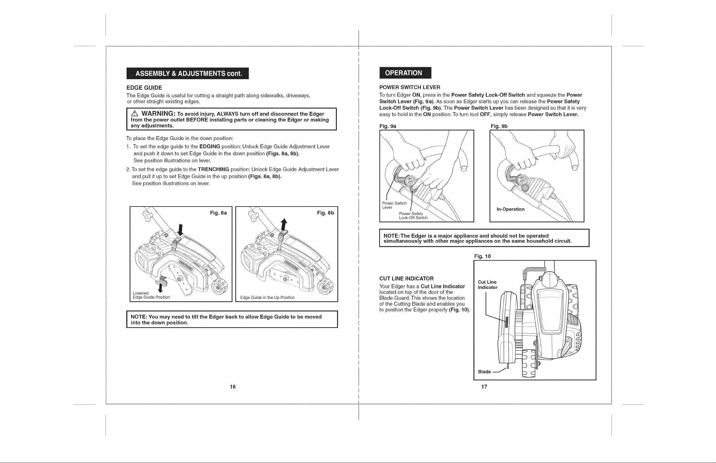
EDGE GUIDE
The Edge Guide is useful for cutting a straight path along sidewalks, driveways,
or other straight existing edges.
from the power outlet BEFORE installing parts or cleaning the Edger or making
i A WARNING: To avoid injury, ALWAYS turn off and disconnect the Edger
any adjustments.
To place the Edge Guide in the down position:
1. To set the edge guide to the EDGING position: Unlock Edge Guide Adjustment Lever
and push it down to set Edge Guide in the down position (Figs. 8a, 8b).
See position illustrations on lever.
2.To set the edge guide to the TRENCHING position: Unlock Edge Guide Adjustment Lever
and pull it up to set Edge Guide in the up position (Figs. 8a, 8b).
See position illustrations on lever.
Fig. 8a
Fig. 8b
POWER SWITCH LEVER
To turn Edger ON, press in the Power Safety Lock-Off Switch and squeeze the Power
Switch Lever (Fig. 9a). As soon as Edger starts up you can release the Power Safety
Lock-Off Switch (Fig. 9b). The Power Switch Lever has been designed so that it is very
easy to hold in the ON position. To turn tool OFF, simply release Power Switch Lever.
Fig. 9a Fig. 9b
Power Switch
Lever
Power Safety
Lock-Off Switch
NOTE: The Edger is a major appliance and should not be operatedsimultaneously with other major appliances on the same household circuit.
in-Operation
Lowered
Edge Guide Position Edge Guide in the Up Position
i OTE: You may need to tilt the Edger back to allow Edge Guide to be moved
into the down position.
16 17
CUT LINE INDICATOR
Your Edger has a Cut Line indicator
located on top of the door of the
Blade Guard. This shows the location
of the Cutting Blade and enables you
to position the Edger properly (Fig. 10).
Fig. 10
Cut Line
indicator
L
Blade

EDGINGOPERATION
EDGING OPERATION cont.
/tk WARNING: Make sure that other peopJe and pets are at Jeast 100 feet
away from Edger.
NOTE: When there is heavy overgrowth of grass over the paved surface, the grass
may drag on the Guard. An initial cut may be required with the Edger on the grass
side. This will require lifting up the Edge Guide and may require reducing the depth
of cut (See EDGE GUIDE and CUTTING DEPTH ADJUSTMENT instructions).
Because of the direction of the Blade rotation, the Edger can kickback towards the
operator if it hits an obstruction such as thick, matted grass. Keep a firm grasp on
the Handle, especiaJJy when edging in thick, matted material. When using the Edger
along a paved surface, keep both rear wheels on the pavement.
1. Set cut depth at 1"(see pg. 15). Locate Edge Guide Adjustment Lever to set Edge Guide
in the down position. See EDGE GUIDE section (pg. 16).
2. Before starting the Edger, line up the tool so the Edge Guide rests against the edge
of the paved surface (Fig.11). The Cut Line Indicator is helpful in lining up the Edger
blade to the cut path. Both Rear Wheels should be on the paved surface when edging.
Fig. 11
surface
For the first edging of the season, it is best to move forward slowly because the
grass is thickest then. Subsequent edging will be take less time. If the tool slows down,
back it up an inch or two until the blade comes up to normal speed. During edging some
sparks may be generated from hitting stones or paved surface. This is normal.
Do not attempt to edge when the grass or soil is wet or moist - for electrical safety and
to prevent clogging of the blade chamber. If you must edge under conditions that cause
the blade chamber to become clogged, release Power Switch Lever, wait for blade to
come to a complete stop, UNPLUG TOOL. Remove the clogged material with a stick.
To continue to operate the Edger in a clogged condition will seriously overload the motor.
Fig. 12a Fig. 12b
Avoiding
Kickback
Tilt the Handle down so
the blade isabove the ground
Edging with
Edge Guide
3. To avoid kickback of Edger, tilt the Handle down so the blade is above the ground (Fig. 12a).
4. Turn Edger On and allow blade to spin without moving tool.
5. Slowly lift the Handle to lower the Blade, finding the edge of the paved surface (Fig. 12b).
Use the Cut Line Indicator to help position the Edger. Start edging, moving the tool forward
slowly along edge of paved surface, keeping the Edge Guide pressed lightly against the
pavement edge.
NOTE: ALWAYS stand to the left of the HandJe. Any debris thrown by the Edger |
would be coming from the BJade Guard area on the right of the Edger
18 19
z_ CAUTION: DO NOT ATTEMPT to uncJog the bJade chamber by dropping or
tapping the Edger on the ground or pavement. This can damage the Edger. Keep
hands clear of Edge Guide and BJade when cleaning, as these wear to very sharp
points during edging.
1

TRENCHINGAND LANDSCAPING OPERATION
The Edger can also be used for Trenching.The blade will leave a small trench for placing
wiring underground.
Because of the direction of the Blade rotation the Edger can kickback towards the operator
if it hits an obstruction such as thick, matted grass. Keep afirm grasp on the Handle,
especially when trenching in thick, matted material.
The Edger can be used in Landscaping applications, including cutting along the edges
of flower and shrubbery beds, around trees, and cutting in preparation for sod removal.
While trenching and landscaping, the Edge Guide can interfere with moving the Edger
through hard soil or sod. For this reason trenching and landscaping are done with the
Blade only and without use of the Edge Guide. Locate the Edge Guide Adjustment Lever
and put Edge Guide in the up position. Refer to illustrations on Lever.
Before trenching, inspect and ensure there are no exposed or buried cables, pipes
or other objects that may create a hazard or interfere with operating the Edger.
Set depth to only that required for the job.
i NOTE: ALWAYS stand to the left of the Handle. Any debris thrown by the Edger
would be coming from the Blade Guard area on the right of the Edger.
Do not overload. If tool slows down, pull back slightly and wait until blade comes up to
normal speed.
REMOVING AND ATTACHING THE BLADE
The blade, two spacers and hex head nut with conical washer should be attached to your
Edger in the order shown (Fig. 13). Check that the blade has been properly mounted before
using your Edger.
The Edger Blade has two wear indicators that show when the original blade needs to be
replaced. When the blade wears to the small holes, it should be replaced.
Hex Head Nut
with conical washer --_
Blade
Indicator
Hole
i
Top Spacer
Bottom
Spacer
i
i
Fig. 13 1
Indicator
Hole
Shaft
i Z_ WARNING: DO NOT use Edger with any type of accessory or attachment.
Such usage might be hazardous.
20 21
!
NOTE: To increase blade life, keep initial cutting depth
at minimum and increase depth setting as blade wears.
i

REMOVINGTHEBLADEFORREPLACEMENT
_ WARNING: To avoid injury, ALWAYS turn off and disconnect the Edger from the
power outlet BEFORE installing parts or cleaning the Edger or making any adjustments.
i A CAUTION: BLADE ROTATES momentarily after power switch is released. Wait
for blade to come to a complete stop. Blade is sharp, wear work gloves when replacing.
1. Use a crescent wrench to hold the outer spacer in place, which will keep the blade
from turning.With an additional crescent wrench, loosen the hex head nut with conical
washer (Fig. 14a).
2. Remove hex head nut with conical washer, spacer and blade.
GENERAL MAINTENANCE
Keep your Edger clean and in good repair for maximum long-lasting performance.
Before each use, inspect the switch and cord for damage. Check for damaged, missing,
or worn parts. Check for loose screws, misalignment, moving parts that are jammed,
or any other conditions that may affect the operation. If abnormal vibration or noise occurs,
turn off the tool immediately and have the problem corrected before further use.
DO NOT use the Edger if it has any broken parts. Have damaged, missing, worn or broken
parts replaced before using Edger.
When servicing a tool, use only identical replacement parts. Use of unauthorized parts
or failure to follow maintenance instructions may create a risk of electric shock or injury.
BLADE CARE
Hex Head Nut --_
with conical washer
Blade-
Indicator
ATTACHING THE NEW BLADE
NOTE: Clean off debris from blade and all mounting hardware.
1. Be sure inner spacer is on shaft -"flats" in spacer hole must engage with "flats"
on shaft (Fig 14b).
2. Place the blade on the shaft over the inner spacer.
3. Hold the blade against the inner spacer and install the outer spacer,
again aligning the flats in the spacer with the flats on the shaft.
4. Install the hex head nut with conical washer. Use a crescent wrench to hold the
outer spacer in place, which will keep the blade from turning. With an additional crescent
wrench, firmly tighten the hex head nut with conical washer (Fig 14a).
NOTE: Replace the hex head nut with conical washer ONLY with identical
replacement part; see Parts List.
Fig. 14b
Indicator
Hole
The cutting blades are made from high quality, hardened steel and with normal use,
they will not require resharpening. However, if you accidentally hit a wire fence, stones,
glass or other hard objects, you may put a nick in the blade. There is no need to remove
this nick as long as it does not interfere with the movement of the blade. If it does interfere,
unplug the Edger and use a fine-toothed file or sharpening stone to remove the nick.
from the power outlet BEFORE installing parts or cleaning the Edger or making
IA WARNING: To avoid injury, ALWAYS turn off and disconnect the Edger
any adjustments.
If you drop the Edger, carefully inspect it for damage. If the blade is bent, housing cracked,
or handles broken, or if you see any other condition that may affect the Edger's operation,
have Edger repaired by a Craftsman or other qualified service dealer before putting it back
into use.
CLEANING
Fertilizers and other garden chemicals contain agents that greatly accelerate the corrosion
of metals. If you use the Edger in areas where fertilizers or chemicals have been used, it
should be cleaned immediately afterwards. Do Not store the tool on or adjacent to fertilizers
or chemicals.
When cleaning, DO NOT immerse tool in water or squirt with a hose.
Never let any liquid get inside the tool.
Wipe all exposed parts with a damp cloth. You may lubricate only metal parts with a light
petroleum based oil.
Z_ WARNING: To avoid injury, ALWAYS turn off and disconnect the Edger
from the power outlet BEFORE installing parts or cleaning the Edger or making
any adjustments.
A CAUTION: BLADE ROTATES momentarily after power switch is released.
Wait for blade to come to a complete stop.
!
1
i
1
22 23

STORAGE
StoretheEdgerindoorswhennotinuse.Itshouldbestoredinadryplace,highupor
lockedinaplacethatisoutofthereachofchildren.
Edgermaybestoredbyhangingbyhandle.DONOThangEdgerwiththePowerSwitch
Leverdepressed!BesurePowerSwitchLeverisfreeofcontactwhenhanging.
/
/
\
i _ WARNING: Be sure the Edger is unplugged before storing.
DO NOT hang Edger by Power Switch Lever.
Remove and clean off any debris from the outside of the Edger and inside of Blade Guard
before storage.
i z_ WARNING: The use of attachments or accessories that are not |
recommended for this tool might be dangerous and could result in serious injury.
REPLACEMENT BLADES
Replacement blades are available at Sears stores or Sears.com.
The replacement blade for your Edger is Sears item number #11000 and #86880.
Visit your local Sears store or other Craftsman outlets or shop sears.corn/craftsman.
i
/
/
\ •
\
\,\
\
]
1
\\
/\
/ \
\
\\\\
\ /
\
\
/
24
',\ \\
\\
i
25

12 Amp
Electric Lawn Edger
The model number will be found on thenameplate ofthe Edger.
Toorder parts, call 1-888-331-4569
Model No. 172.796570
item No. Parts No. Part Description
1 GLE150U 1-1 Self Tapp!n9 Screw
2 GLE150U1-2 Right Switch Cover
3 GLE150U1-3 Torsional Spring
4 • GLE150U1-4 L Connector Plug
5 GLE150U1-5
7 GLE150U1-6
8 GLE150U 1-7
9 GLE150U1-8
10 GLE150U1-9
11 GLE150U1-10
12 GLE150U1-11
13 GLE150U1-12
14 GLE150U1-13
15 GLE150U1-14
16 GLE150U1-15
tO
17 GLE150U1-16
18 GLE150U1-17
19 GLE150U1-18
Switch Lever
Switch
Handle
Tube Plug
Self Tappin_c[Screw
Switch Lever
Left Switch Cover
[ Compression Spr!ng
Button
Insulation Sheath
Pushing Rod II
Cable Hook
Screw
Inner Line
20 GLE150U 1-19 R!pple Tube 1
21
22
23
24
25
26
27
29
4O
41
42
47
48
49
5O
51
GLE150U1-20
GLE150U1-21
GLE150U1-22
GLE150U1-23
GLE150U1-24
GLE150U1-25
GLE150U1-26
GLE150U1-28
GLE150U1-40
GLE150U1-41
GLE150U1-42
GLE150U1-47
GLE150U1-48
GLE150U1-49
GLE150U1-50
GLE150U1-51
Pushing Rode III
Washer
Nut
Locking Knob
Bolt
Bolt
Nut
Blade
Cord Clamp
Self Tapp!ng Screw
Rear Roller Shaft
Sleeve
Roller
Self Tapping Screw
Washer
Spring Pin
Qty.
item No. Parts No. Part Description Qty.
4
1
1
1
1
1
1
1
5
1
1
1
1
1
1
1
2
1
1
4
3
2
1
1
1
2
1
1
2
1
2
2
4
1
2
52 GLE150U1-52 Rear Cover 1
53 GLE150U1-53 Roller Guard 2
55 GLE150U1-55 Strip 1
57 GLE150U1-57 Ornament cover 1
58 GLE150U 1-58 Self Tapping Screw 8
60 GLE150U1-60 Nut 9
61 GLE150U1-61 Rear Bracket 1
62 GLE150U1-62 Stator 1
63 . GLE150U1-63 _ Front Bracket _ 1
64
65
66
67
68
69
70
71
GLE150U1-64
GLE150U1-65
GLE150U1-66
GLE150U1-67
GLE150U1-68
GLE150U1-69
GLE150U1-70
GLE150U1-71
Ball Bearing
Washer
Spring Washer
Screw
Rotor
Self Tapping Screw
Bearing Cover
Ball Bearing
73 l GL.E150U1--73 _ Gear Box Body
74 = GLE150U1-74 , Oi! Seal Bearing
75
76
77
78
79
8O
81
82
83
84
85
86
87
88
89
90
91
GLE150U1-75
GLE150U1-76
GLE150U1-77
GLE150U1-78
GLE150U1-79
GLE150U1-80
GLE150U1-81
GLE150U1-82
GLE150U1-83
GLE150U1-84
GLE150U1-85
GLE150U1-86
GLE150U1-87
GLE150U1-88
GLE150U1-89
GLE150U1-90
GLE150U1-91
Screw
Output Shaft Set
Gear Box Cover Assembly
Screw
Detent Block
Left/Rignt Housing
Screw
Screw Washer Assembly
Nut
Front Wheel
Front Roller Shaft
Connectinq Plate
Compression Spr!ng
Pin Shaft
Cylindrical Pin
Front Spanner
Cylindrical Pin
1
2
2
2
1
3
1
1
1
1
4
1
1
3
1
1
1
3
2
1
1
1
1
1
1
1
1
12 Amp
Electric Lawn Edger
Model No. 172.796570
tO
"4
item No.
92
93
94
95
96
97
98
99
101
102
105
106
107
108
109
110
111
113
114
115
116
117
118
119
201
2O4
2O5
2O6
2O7
2O8
Parts No.
GLE150U1-92
GLE150U1-93
GLE150U1-94
GLE150U1-95
GLE150U1-96
GLE150U1-97
GLE150U1-98
GLE150U1-99
GLE150U1-100
GLE150U1-101
GLE150U1-105
GLE150U1-106
GLE150U1-107
GLE150U1-108
GLE150U1-109
GLE150U1-110
GLE150U1-111
GLE150U1-113
GLE150U1-114
GLE150U1-115
GLE150U1-116
GLE150U1-117
GLE150U1-118
GLE150U1-119
GLE150U1-201
GLE150U1-204
GLE150U1-205
GLE150U1-206
GLE150U1-207
GLE150U1-208
The model number will be found on thenameplate of the Edger.
Toorder parts, call 1-888-331-4569
Part Description
Brush Holder
Carbon Brush(Pair)
Compress!on SDrin 9
Brush Holder
Washer
Terminal
Brand Label
Rated Label
Lever
Linkage
Guide Bar
Pin
Holder II
Gear Box Assembly
Screw
Felt Seal
Rivet
Screw
Knob
Button
Spring
Holder I
Screw
Guard
Switch Cover
Motor Set
Front Wheel Assembly
Adiustment Block
Brush Holder Assembly
Guard Assembly
Qt_:
2
1
2
2
4
2
1
1
1
1
1
1
1
1
4
2
2
2
1
1
1
1
2
1
1
1
1
1
2
1

Manual del Operador
12.0 Amp
Bordeadora
®
de C6sped
El_ctrica
lVlodelo No.
172.796570
PRECAUCION:
Lea, entienda y siga todas las reglas de
seguridad e instrucciones de operaci6n en
este manual antes de usar este producto.
Sears Brands Management Corporation,
Hoffman Estates, IL 60179 U.S.A.
www.craftsman.com
_us
Intertek
3025736
,,GARANT{A
• SEGUBIDAD
• ENSAMBLAJE
• OPEBACION
• MANTENIMIENTO

Garanfia..................................................................................................... Pa.gina2
Sl'mbolos de Seguridad ............................................................................. Pagina 3
Instrucciones de Seguridad ....................................................................... Pa.ginas4-9
Desempaque .............................................................................................. Pagina 10
Descripci6n ................................................................................................. Pa.ginas 11-12
Ensamblaje y Ajustes................................................................................. Paginas 13-16
Operaci6n................................................................................................... Pa.ginas 17-22
Mantenimiento ............................................................................................ Paginas 23-24
GARANTIA LIMITADA DE CRAFTSMAN
DURANTE DOS ANOS desde la fecha de venta, este producto est,.
garantizado contra defectos de materiales o mano de obra.
CON EL COMPROBANTE DE VENTA, un producto defectuoso ser_.
reemplazado gratis.
Para detalles sobre c6mo obtener un reemplazo gratis con la garanfia,
visite la pa.gina web: www.craftsman.com/warranty
Esta garanfia no cubre la cuchilla, al ser una pieza reemplazable que puede
desgastarse con el uso normal dentro del periodo de garanfia.
Esta garanfia le otorga derechos legales especfficos, y tambien puede tener
otros derechos que varfan de estado a estado.
Sears Brands Management Corporation, Hoffman Estates, IL 60179
ADVERTENClA: Parte del polvo que se origina al usar herramientas
el6ctricas para el jardin y el c_sped contienen sustancias quimicas queen el
Estado de California se conocen como causantes de c_ncer y defectos al nacer
u otros dahos al sistema reproductivo.
iGUARDE ESTAS INSTRUCCIONES!
iLEA TODAS LAS INSTRUCCIONES!
El prop6sito de los simbolos de seguridad son para Ilamar su atenci6n sobre posibles
peligros. Los simbolos de seguridad y sus explicaciones, merecen toda su atenci6n y
entendimiento. Las advertencias del simbolo NO por si solas eliminan cualquier peligro.
Las instrucciones y advertencias que se dan, no son sustitutos de las medidas adecuadas
de prevenci6n de accidentes.
z_ ADVERTENClA: ASEGURESE de leer y entender todas ins instrucciones
de seguridad en este manual, incluyendo todos los simbolos de alerta de seguridad
tales como "PELIGRO", "ADVERTENClA" y "PRECAUClON", ANTES de utilizar esta
herramienta. Si no se siguen todas las instrucciones se puede provocar una descarga
el6ctrica, incendio y / o lesiones personales graves.
SlGNIFICADO DE SilVIBOLOS
SJlViBOLO DE ALERTA DE SEGURIDAD: IndicaPELIGRO,ADVERTENClA,
O PRECAUCION. Puede set usado en asociaci6n con otros simbolos o figuras.
El no seguir esta advertencia de seguridad DARA como
resultado graves lesiones para usted o para otros.
Sign siempre las precauciones de seguridad para reducir el
riesgo de incendio, choque el6ctrico y lesiones personales.
Z_ ADVERTENClA J resultado lesiones graves para usted o para otros. Sign
[Z_ PRECAUClON 1
PREVENCION DE DAI_OSY IVlENSAJES INFORMATIVOS
Estos comunican al usuario informaci6n importante y / o instrucciones que podrian causar
daSos al equipo o a otra propiedad si no se siguen dichas instrucciones. Cada mensaje va
precedido de la palabra "NOTA:" como en el siguiente ejemplo:
NOT.&:El equipo y / o daSos a la propiedad pueden resultar si estas instrucciones
[
no se siguen.
i El no seguir esta advertencia de seguridad PUEDE dar como
siempre ins precauclones de seguridad para reducir el riesgo
de incendio, choque el6ctrico, y lesiones personales.
El no seguir esta advertencia de seguridad PODRIA dar como
resultado lesiones personales para usted u otros o podria
causar da5os a la propiedad. Sign siempre las precauciones
de seguridad para reducir el riesgo de incendio, choque
el6ctrico y lesiones personales.
z_ ADVERTENCIA: el funcionamiento de cualquier
Bordeadora puede resultar en que ciertos objetos extra_os sean
lanzados hacia los ojos, Io que puede provocar daSos graves en
los mismos. Antes de comenzar a operar la herramienta el6ctrica,
SIEIVIPREutilice gafas de seguridad o gafas de seguridad con
protecci6n lateral y un protector de cara completo, cuando sea
necesario. Se recomienda una M_scara Protectora de Visi6n
Amplia para usar encima de los anteojos o gafas de seguridad
est_ndar con proteccibn lateral, disponible en las tiendas Sears
o Puntos de Venta Craftsman.
]
2 3

/iX ADVERTENCIA: si se utiliza correctamente La Bordeadora electrica es f_cil de
manejar yes una herramJenta eficaz y r_pJda,si se usa incorrectamente o sin las debidas
precauciones puede convertirse en un instrumento peligroso. Para un trabajo agradable y
seguro, SIEMPRE debe cehirse estrictamente con las normas de seguridad que figuran en
este manual.
z_ ADVERTENClA: ASEGURESE de leer y entender todas las Jnstruccionesen este
manual, antes de usar esta Bordeadora ei6ctrJca. Si no se siguen todas las instrucciones
listadas abajo se puede provocar una descarga el6ctrica, incendio y / o lesiones personales
graves.
Z_ ADVERTENClA: Para evitar errores que podrian causar lesiones graves, NO
conecte esta herramienta hasta que se haya leido y entendido las siguientes instrucciones.
SEGURIDAD EN EL AREA DETRABAJO
1. SIEMPRE evite condiciones peligrosas. NO la use en _reas hQmedas o mojadas o la
exponga a la Iluvia.
2. NO Jaopere en presencia de liquidos infJamables, gases o polvos. Las herramientas
el6ctricas producen chispas que pueden encender el polvo o gases.
3. SIEIVlPRE mantenga a Jos espectadores y visitantes a una distancia segura mientras
opera una Bordeadora. NUNCA permita que los niSos est6n cerca de la herramienta.
Los objetos lanzados pueden causar lesiones a personas que est6n la zona.
4. ASEGURE SUS HERRAMIENTAS ANTE LOS NI_IOS manteni_ndola bajo candados
e interruptores maestros. Guarde bajo Ilave las herramientas cuando no est6n en uso.
Esta Bordeadora no es un juguete.
5. NO use su Bordeadora sin una iluminaci6n adecuada. SIEMPRE aseg_rese de que
usted pueda ver los bordes.
6. ANTES de usar la Bordeadora, quite las pie@as, palos, escombros u objetos que podrian
enredarse o ser arrojados por la Bordeadora.
SEGURIDAD PERSONAL
Z_ ADVERTENClA: Durante el funcionamJento de cuaJquier Bordeadora objetos extraSos I
podrian set lanzados, Io cual puede resultar en lesJones personales o daSos a la propJedad. |
SIEMPRE use equJpo de segurJdad adecuado.
1. CONOZCA su herramienta. Lea el manual del operador cuidadosamente. Aprenda las
aplicaciones y Jimitaciones de su Bordeadora el6ctrica, asi como los posibles riesgos
especificos relacionados con esta herramienta.
2. ALERT,&,fijese en Ioque est,. haciendo y use el sentido comun cuando utilice esta herramienta.
3. NO use la herramienta cuando este cansado o bajo la influencia de drogas, alcohol o
medicamentos. Un momento de distraccion mientras opera esta herramienta puede resultar
en graves lesiones personales.
4. VJSTASE de manera adecuada. Use guantes de goma y calzado con suela sustancial de caucho,
cuando se trabaja al aire libre. NO utilice las herramientas del cesped y el jardin con los pies
descalzos o con sandalias abiertas. Use pantalones largos y mangas largas para proteger las
piernas y los brazos. Las Bordeadoras pueden recoger objetos como rocas y hacerlos volar a
gran velocidad. NO use ropa suelta o joyas. Mantenga su cabello, ropa y guantes alejados de
las piezas en movimiento. Prendas de vestir sueltas o el cabello largo pueden quedar atrapados
en las piezas m6viles.
4
SEGURIDAD PERSONAL cont.
5. USE EQUJPO DE SEGURJDAD. Use siempre gafas de seguridad o galas de seguridad
con protecci6n lateral o careta completa, calzado adecuado de trabajo con suela de goma
antideslizante, guantes de goma antideslizante para trabajo pesado y mascara protectora
del polvo o un respirador, y protecci6n para los oidos. Use un casco duro apropiado para
estas condiciones.
6. NO se estire demasiado. Mantenga la postura y el equilibrio en todo momento. Un buen
apoyo y equilibrio permiten un mejor control de la herramienta en situaciones inesperadas.
USO DE LA HERRAIVllENTAY CUIDADOS DE SEGURIDAD
de usar esta herramienta. El no seguir todas las instrucciones puede resultar en una
/tk ADVERTENClA: ASEGURESE de leer y entender todas Jasinstrucciones antes
descarga el6ctrJca, JncendJoy / o lesJones personales graves.
1. NO use Jaherramienta si el interruptor no "Enciende"o "Apaga." Una herramienta que
no puecle ser controlada con el interruptor es peligrosa y debe ser reparada.
2. DESCONECTE el enchufe de la fuente de energia antes de realizar cualquier ajuste,
cambiar accesorios o guardar Jaherramienta. Estas medidas de seguridad preventivas
reducen el riesgo de que la herramienta se encienda accidentalmente.
3. MANTENGA las herramientas fuera del alcance de los ni_os y otras personas sin
entrenamiento. Los niSos NO DEBEN operar la herramienta. Las herramientas son
peligrosas en manos de personas inexpertas.
4. CUIDE las herramientas. SIEMPRE mantenga las herramientas de corte limpias y
en buen estado.
5. VERIFIQUE Jaalineaci6n o cubierta de las piezas m6viJes, rotura de piezas y
cualquier otra condici6n que puedan afectar el funcionamiento de la herramienta.
Si la herramienta esta daSada debe hacerle el servicio antes de usarla. Muchos
accidentes son causados por un mantenimiento incorrecto de la herramienta.
6. USE SOLAMENTE las cuchillas de corte que se recomiendan para esta Bordeadora.
Las cuchillas que pueden ser adecuadas para una Bordeadora pueden resultar peligrosos
si se utilizan en otra Bordeadora.
SEGURIDAD ELI_CTRICA
]
los terminales del enchufe cuando conecte o desconecte
/!k ADVERTENCIA: No permita que losdedos toquen
el cable de extensJ6n desde el enchufe.
•Las herramientas con doble aislamiento estan equipadas
con un enchufe polarizado (un contacto es m_s ancho
que el otto y requieren el uso de un cable de extensi6n
polarizado.) El enchufe de la Bordeadora entra en un cable
de extensi6n polarizado de una sola manera. Si el enchufe
no encaja completamente en el cable de extensi6n, invierta
el enchufe. Si aQn asi el enchufe no encaja, obtenga un cable
de extensi6n polarizado correcto.
Un cable de extensi6n polarizado requiere el uso del tomacorriente polarizado. Este enchufe
encajara en el tomacorriente polarizado de una sola manera. Si el enchufe no encaja
completamente en el tomacorriente, invierta el enchufe. Si aun asi no entra, Ilame a un
electricista calificado para que instale un tomacorriente adecuado. No cambie ni altere el
equipo del enchufe, cavidad del cable de extensi6n o el enchufe del cable de extensi6n de
ninguna manera.
5
1
J

SEGURIDAD ELI_CTRICA cont.
2. Doble aislamiento rSlelimina la necesidad del cable de alimentaci6n de tres hilos
a tierra y del suministro de energia del sistema a tierra. Aplicable s61o a la Clase II
(doble aislamiento). Esta Bordeadora es una herramienta de doble aislamiento.
/tk ADVERTENCIA: GFCI (interruptor de circuito de falla de la tierra) debe proporcionar
protecci6n en todos los circuitos o tomacorrientes que se utilizaran para las herramientas
electricas del cesped yjardin. Los receptaculos estan disponibles con protecci6n GFCI
incorporada y se deben utilizar para esta medida de protecci6n.
Z_ ADVERTENCIA: El doble aislamiento NO reemplaza las precauciones normales de
seguridad cuando se opera esta herramienta.
3. ANTES de enchufar la herramienta, ASEGURESE que el voltaje suministrado est6 dentro
del voltaje especificado en los datos de la placa de la herramienta. NO use herramientas"
AC solamente" en fuente de alimentaci6n DC.
4. NO exponga las herramientas a la Iluvia o a condiciones de humedad o el uso de
herramientas el_ctricas en lugares mojados o humedos. La entrada de agua en una
herramienta el6ctrica aumentara el riesgo de descarga el6ctrica.
5. Si es inevitable la utilizaci6n de la herramienta el_ctrica en lugares h_medos,
utilice siempre un interruptor de circuito de falla de la tierra para suministrar
energia a la herramienta. SlEMPRE USE guantes y calzado de electricista de goma
en condiciones hQmedas.
6. AI operar una herramienta el6ctrica en exteriores, SlEMPRE utilice un cable de extensi6n
para intemperie marcado "W-A" o "W". Estos cables estan diseSados para uso exterior y
reducen el riesgo de descarga el6ctrica.
7. INSPECCIONE los Cables de las herramientas en busc.a de da_os. Repare los cables
de la herramienta en un Centro de Servicio Sears. ASEGURESE de mantenerse
constantemente al tanto de la ubicaci6n del cable y mant6ngalo lejos de la cuchilla de corte.
8. NO abuse de la extensi6n. NUNCA use el cable para transportar Ja herramienta ni
para sacar el enchufe del tomacorriente. Mantenga el cable alejado del calor, aceite,
bordes cortantes o piezas m6viles. Reemplace los cables daSados inmediatamente.
Los cables daSados aumentan el riesgo de descarga el6ctrica.
CABLES DE EXTENSION
Utilice un cable de extensi6n adecuado. Utilice 0NICAMENTE cables aprobados por
Underwriters Laboratories (UL). Otros tipos de cables de extensi6n pueden causar una caida
de volatje, Io que resulta en una p6rdida de potencia y sobrecalentamiento de la herramienta.
Para esta herramienta se recomienda un AWG (Cable de Calibre Americano) de un tamaSo
de por Io menos 14 calibres para una extensi6n de 25 - pies o menos de Iongitud. Use el de
calibre 12 con un cable de extensi6n de 50 pies. Cables de extensi6n de 100 pies o m_s
largos no se recomiendan.
Recuerde, un tamaSo de cable de calibre m_s pequeSo tiene mayor capacidad que uno
de mayor nQmero (el cable de calibre 14 tiene mayor capacidad que el cable de calibre 16,
el cable de calibre 12 tiene mayor capacidad que el calibre 14). En caso de duda utilice el
n0mero menor.
AI operar una herramienta el6ctrica en exteriores, utilice una extensi6n marcada "W-A" o "W".
Estos cables estan diseSados para uso en exteriores y reducen el riesgo de descarga el6ctrica.
el cablede manera que no quede atrapado en los arbustos, cercados, troncos de 4rboles,
j rk PRECAUClON: Mantenga el cable de extensi6n fuera del area de trabajo.Coloque
cortadoras de cesped u otros obst4culos mientras esta trabajando con la Bordeadora.
CABLES DE EXTENSION cont.
ADVERTENCiA: Inspeccione los cordones de extensi6n antes de carla uso.
Si est_ daSado reemplace inmediatamente. Nunca use la herramienta si el came est_
daSado ya que si toca la parte da5ada puede causar una descarga el6ctrica, Io que
resultar_ en lesiones graves.
SJMBOLOS DE SEGURJDAD PARA SU HERRAMIENTA
La etiqueta de su herrarnienta puede incJuir Jos siguientes sJrnboJos:
V.................................................................... Voltios
A.................................................................... Amperios
Hz.................................................................. Hertz
W................................................................... Watts (Vatios)
rain ................................................................ Minutos
,_ ................................................................. Corriente Alterna
................................................................ Corriente Directa
no .................................................................. Velocidad sin carga
[] ................................................................. Construcci6n Clase II
.../rain ............................................................ Revoluciones o Golpes por minuto
Z_ .................................................................. Indica peligro, advertencia o precauci6n.
SERVICIO DE SEGURIDAB
1. Si aiguna pieza de esta Bordeadora faita o se rompe, se dobla o falia de alg_n
modo, o si cuaiquier componente el6ctrico no funciona adecuadamente: APAGUE
el interruptor de encendido y desconecte el cable de alimentaci6n de la Bordeadora y
reemplace las piezas que faltan, las que fallan o daSadas ANTES de reanudar la
operaci6n.
2. El servicio de mantenimiento debe ser realizado en Centros de Reparaci6n Sears
o en un distribuidor autorizado de servicios. Servicio o mantenimiento realizado por
personal no calificado puede resultar en un riesgo o lesi6n.
3. AI reparar una herramienta, utilice _nicamente piezas de repuesto id6nticas.
Siga las instrucciones en la secci6n de mantenimiento de este manual. El uso de
piezas no autorizadas o el no seguir las instrucciones de mantenimiento pueden crear
un riesgo de choque el6ctrico o lesiones.
REGLAS DE SEGURIDAD PARA LAS BORDEADORAS ELI_CTRICAS
1. CONOCER su Bordeadora el6ctrica. Lea el manual del operador cuidadosamente.
Aprenda las aplicaciones y limitaciones, asi como los posibles riesgos especificos
relacionados con esta herramienta. A raiz de esta regla se reduce el riesgo de una
descarga el6ctrica, incendio o lesiones graves.
2.
NO use su Bordeadora sin una iluminaci6n adecuada. SlEIVIPRE aseg0rese de que
usted pueda ver los bordes.
3.
Utilice la Bordeadora SOLAIVIENTE cuando el pasto y la hierba est6 seca no mojada.
4.
IV]ant6ngase siempre a la izquierda de la manija. Los desechos arrojados por la
Bordeadora vienen del Area de la cuchilla a la derecha de la Bordeadora.
5.
SlEMPRE se deben quitar objetos tales como piedras, palos y desechos de los bordes del
camino de acceso a la Bordeadora que se podrian enredar, o ser arrojados por la misma.
6.
Para reducir el riesgo de rebote, se debe trabajar lejos de cualquier objeto s61ido cercano,
como una pared, escalones, piedras grandes, arboles, etc. Tenga cuidado cuando trabaje
cerca de objetos s61idoso en el viento. Si es necesario, bordee o recorte en las Areas con
la mano.
iEsto significa atenci6n! Su seguridad esta en juego.
7

REGLAS DE SEGURIDAD PARA LAS BORDEADORAS ELECTRICAS cont.
7. SlEMPRE sujete la Bordeadora en la manija con ambas manos y NUNCA trate de
agarrar ni cerca o debajo del protector de la cuchilla.
8. EVlTE un arranque o encendido accidental. NO enchufe la Bordeadora con el dedo
en la palanca del interruptor de encendido.
9. NO cargue la Bordeadora por el cable de extensi6n, ni tire del cable para desconectarlo
del tomacorriente. Mantenga el cable alejado del calor, aceite y bordes afilados.
10. NO FUERCE la Bordeadora. No trate de cortar mas para Io que la Bordeadora ha sido
diseSada. Se hara un trabajo mejor y con menos posibilidad de lesiones si se utiliza en
la velocidad para la que fue diseSada.
11.IVlANTENER la Bordeadora con cuidado. SIElVIPRE revise el cable de extension y
reemplacelo siesta daSado.
12. IVlANTENGA la Manija seca, limpia, libre de aceite y grasa. Utilice un paso limpio para la
limpieza. NO utilice disolventes, liquidos de frenos, gasolina, petrOleo o productos para
limpiar la Bordeadora. Pueden daSar las piezas de plastico.
13. NUNCA, por ninguna raz6n, toque las cuchillas de corte u otras partes m6viles durante el uso.
14. MANTENGA el Protector de la Cuchilla en su lugar yen buen estado. Mantenga el protector
colocado sobre la cuchilla, mantenga las manos y los pies alejados de la cuchilla de corte.
15. SIElVIPRE guarde en el interior laBordeadora cuando no est6 en uso. Debe set almacenada
en un lugar seco, en un lugar que tenga un seguro, que este fuera del alcance de los niSos.
16. SIEMPRE use s61olas cuchillas que se proporcionan con esta Bordeadora o que se
venden especificamente para la misma. El uso de cualquier otra cuchilla puede causar
una situaci6n peligrosa.
17. SIEIVIPRE mantenga las aberturas de ventilaci6n del motor libre de residuos.
18. IVlANTENGA A LOS ESPECTADORES LEJOS a una distancia segura del Area de trabajo,
especialmente los niRos. AsegQrese de que las personas y los animales dom_sticos est_n
por Io menos a 100 metros de distancia.
Z_ ADVERTENCIA: Algunas particulas de polvo creado pot las herramientas
de jardin y c_sped contienen quimicos conocidos como causantes de c_ncer,
defectos al nacer u otros daSos al sistema reproductivo. AIgunos ejemplos de
estas sustancias quimicas son:
• Compuestos en fertilizantes, herbicidas, pesticidas e insecticidas.
• Ars_nico y cromo de madera tratada quimicamente.
El riesgo de estas e×posiciones varia, dependiendo de cuantas veces se hace
este tipo de trabajo. Para reducir la exposici6n a estas sustancias quimicas:
• Trabaje en un _rea bien ventilada.
• Trabajar con equipos de seguridad aprobados, tales como m_scaras
contra el polvo especialmente diseSadas para filtrar particulas
microscop=cas.
Z_ ADVERTENCIA: NUNCA ponga la mano debajo de la Bordeadora
(_rea de la cuchilla) hasta que la halla desconectado y _sta haya parado
completamente. La cuchilla de la Bordeadora seguir_ girando pot
unos segundos despu_s de que se apaga.
REGLAS ADICIONALES PARA UNA OPERACION SEGURA
ADVERTENClA: ASEGURESE de leer y entender todas las instrucciones.
Siestas no se siguen se puede provocar una descarga el_ctrica, incendio y / o
lesiones personales graves.
1. SIEIVIPRE use gafas de seguridad cuando utilice la Bordeadora. Las gafas regulares
o formuladas son parcialmente resistentes. NO son gafas de seguridad.
2. Proteja sus pulmones. Use una mascara facial o mascara contra el polvo si la operaciSn
genera mucho polvo.
3. Proteja los oidos. Use protecci6n personal adecuada para los oidos durante el uso. Bajo
ciertas condiciones, el ruido de este producto puede contribuir a la p_rdida de la audici6n.
4. Todos los visitantes y espectadores deben utilizar el mismo equipo de seguridad que
usa el operador de la herramienta.
5. SIEIVIPRE verifique la herramienta para detectar las piezas da_adas. Verifique la
alineaciSn y cobertura de las piezas mSviles, rotura de piezas y cualquier otra condiciSn
que pueda afectar su operaciSn. Antes de seguir utilizando la herramienta, debera
verificarse el protector o la pieza que est6 daRada y tendra que comprobar
cuidadosamente determinando siesta puede funcionar apropiadamente cumpliendo con
su funciSn. Un protector u otra pieza que est6 daSada debe ser reparada o reemplazada
en Sears o en un distribuidor autorizado de servicios.
6. GUARDE ESTAS INSTRUCCIONES. Consr31telas con frecuencia y uselas
para ense_ar aotras personas que puedan utilizar esta herramienta. Si alguien
toma esta herramienta, asegurese de que tengan tambi_n las instrucciones.
8 9

1.LaBordeadoravienecompletamentearmadaconexcepci6ndelamanija,lacualviene
enpiezasyestaconectadaporuncableadointerno,ydebeserensamblada(Fig.1).
2.Tambi6nseincluyeunabolsacondosperillas ydos tornillos de cabeza curva para
ensamblar la manija.
3. Retire de la caja la Bordeadora con la manija, junto con la bolsa de perillas y tornillos.
Inspeccione su Bordeadora.
4. No bote la caja o el material de empaque hasta que todas las piezas sean examinadas.
Z_ ADVERTENClA: Si cualquier pieza de la Bordeadora falta o est_ daSada,
no la conecte hasta que la pieza daSada sea reparada o sustituida.
Fig. 1
Manija
Dos Perillas yTornillos |
de Cabeza Curva
en bolsa de plastico)
d
L
Retire el Plastico Negro que
Recubre el Tubo de la pieza del
cable entre la manija y el Tubo
Superior.
Manija
Manija cable tubo
revestido con
plAstico negro tubo
tubo superior Superior-
tubo Superior
J
CONOZCA SU BORDEADORA
NOTA: Antes de intentar utilizar este producto, farniliaricese con todas las
caracteristicas de funcionarniento y norrnas de seguridad.
Su Bordeadora tiene un motor el6ctrico fabricado con precisi6n y solamente se debe
conectar a 120 voltios, 60 Hz AC (corriente normal de la casa). La Bordeadora siempre
debe utilizarse con un enchufe GFCI (interruptor de circuito de falla a tierra).
NO opere la Bordeadora en corriente directa (DC). La caida del voltaje podria causar una
gran p6rdida de potencia y el recalentamiento del motor.
Si la Bordeadora no funciona correctamente cuando se conecta Qnicamente a una salida
de 120 voltios, 60 Hz AC, verifique la fuente de alimentaci6n. La Bordeadora viene con
un enchufe el_ctrico y debe ser conectado a un cable de extensi6n adecuada.
Esta Bordeadora tiene las siguientes caracteristicas:
1. Funci6n 2=en=l que convierte la Bordeadora en Zanjadora.
2.3-posiciones de Ajuste de la Profundidad de la Cuchilla con un indicador
(1", 1 'A" y 1 '_").
3. Motor poderoso de 12,0 arnperios, 4700 / rnin (velocidad sin carga) para trabajo
pesado en bordes y zanjas.
4. Manija con diseSo ergon6mico y agarre c6modo reduce la fatiga y rnejora
el control.
5. F_cil acceso a la cuchilla de 7 1/_,,para lirnpiar escombros.
6.2 posiciones de Ajuste de la Longitud del Eje de la Manija.
7. La Palanca de Ajuste de la Gu_a de Borde se sube o baja.
8. Ruedas Traseras de 6 pulgadas y Rueda Delantera con Ajuste de Altura
9. El indicador de linea de corte ayuda a rnantener cortes rectos y nivelados.
]
Tubo Inferior
10 11

CONOZCASU BORDEADORA cont. Fig. 2
Interruptor de Palanca
Interruptor de BIoqueo
de Seguridad-Apagado
Retenedor del Cable
de Extensi6n con Gancho
Tubo Superior
Vista de frente
Indicadorde
la L[nea
de Corte
__ de Ajustede
J-XX- Borde
Palanca
la Gu[a de
Manija
Ruedas
Traseras
Dos Espigas de Enchufe
para el Cable de Extensi6n
Perillas con Tornillos
de Cabeza Curva
Tubo Inferior
Palanca de Ajuste
de la Guia de Borde
Rueda
Delantera
MONTAJE DE LA MANIJA
La manija viene empaquetada en secciones, que estan conectadas entre si por un
cableado interno recubierto que atraviesa el centro de todas las piezas de la manija.
1. Retire con cuidado el material de empaque y las envolturas de plastico que vienen
alrededor de la Bordeadora y las piezas de la manija, teniendo cuidado de mantener
las piezas conectadas.
2. Retire de la bolsa de plastico las Perillas y los Tornillos de Cabeza Curva.
3. Remueva la cubierta de pl_stico negro del tubo de la pieza del cable entre la manija
y el tubo superior (Fig. 1). Esto permitir& que el tornillo pase por el diametro mas
pequeSo de la manija.
4. Deslice la Manija hacia abajo en el extremo del Tubo Superior para alinear los agujeros
(Fig. 3a). Cuidadosamente inserte el tornillo, teniendo cuidado para evitar tocar el alambre
dentro de la manija del eje (Fig. 3b). AsegOrelas apretando la perilla y los Tornillos de
Cabeza Curva.
5,
Deslice hacia abajo el Tubo Superior en el Tubo Inferior, para que se alineen los agujeros.
No retire el plastico negro de recubrimiento del tubo del cable en esta conexi6n. Hay dos
posiciones disponibles para el ajuste de la altura de su preferencia (Fig.4a).
NOTA: Cuando usted primero inserte el tornillo, puede que sea necesario el moverlo
con cuidado para pasar el alambre recubierto en el interior del Tubo). Aseg0ralas apretando
con la segunda Perilla y los Tornillos de Cabeza Curva. (Fig. 4b.)
Fig. 3a Fig. 3b
Fig. 4b
_/I I Los Orificios
III1 de Ventilaci6n
del Motor
Profundidad de Corte
de Mandocon Palanca
de Liberaci6n
Guia de Borde
12
Cuchilla
Protector de
la Cuchilla
NOTA: Aseg0rese de que el cable de alambre se mueve suavemente hacia abajo
en la Manija del Tubo Inferior durante el montaje.
I Z_ PREOAUOI6N: NUNOA use un objeto puntiagudo para sacar los cables recubiertos. I
L I
13

FIJACl6NDECABLEDEEXTENSION
1.Inserteelcabledeextensi6nenelEnchufedeEnergfadelaBordeadora(Fig.5).
2.UnRetenedordelCabledeExtensi6nseanexaalamanijaparareducirlatensi6nen
elcable.Parautilizarestafunci6n,simplementedobleelcabledeextensi6ncomose
muestra,aproximadamenteunpiedesdeelfinal,eins_rteloenelfinaldelretenedor.
Coloqueellazoformadoporeldobladodelcablesobreelgancho(Fig.6a).Tire
suavementedelcableparaasegurarsedequeestabiensituadoenelretenedor(Fig.6b).
3.Mantengaelcabledeextensi6n,launidadylosobst_.culoslejosdeloperadorentodo
momento.Noexpongaelcablealcalor,aceite,agua,obordesfilosos.
Fig.5 Fig.6a
Fig. 6b
AJUSTEDELAPROFUNDIDADDECORTE
Laruedadelanterasepuedeajustarparapermitiruncortemasprofundoomenosprofundo.
Serecomiendalaconfiguraci6nm_.ssuperficialparaaumentarlavidadelacuchilla.
Ajustarelcorteprofundoalaprofundidaddeseada:
Z_ ADVERTENCIA: Para evitar lesiones, siempre apague y desconecte la
Bordeadora del tomacorriente antes de instalar las piezas o antes
i
de limpiarla o de hacer cualquier ajuste.
z_ ATENCION: LA CUCHILLA SIGUE GIRANDO moment_neamente despu_s
i
de apagarse. Espere a que la cuchilla se detenga por completo.
1. Para aflojar la rueda delantera, tire hacia fuera la Palanca de Liberaci6n de la Perilla
de Corte Profundo, ubicada en la parte delantera de la Bordeadora al otro lado de la
Rueda Delantera (Fig. 7a).
2. Ajuste la profundidad de la rueda usando el indicador de profundidad en el soporte de
la rueda y marcas en el frente de la caja (Fig. 7b).
I NOTA: La profundidad recomendada para bordear es de 1 pulgada. i
3. Ajuste la Palanca de Liberaci6n de Corte Profundo empuj_.ndola hacia adentro firmemente.
Fig. 7a Fig. 7b
1
i
i NOTA: El Protector puede arrastrar la maleza gruesa. Para ayudar a reducir I
este efecto se debe reducir la profundidad de corte al mfnimo.
14 15
Profundidad
i
1

GUIA DE BORDE
La guia de borde es Otilpara el corte de un camino recto a Io largo de las aceras, calzadas,
o de otro tipo de borde recto existente.
Bordeadora del tomacorriente antes de instalar las piezas, de limpiarla o de
_ ADVERTENCIA: Para evitar lesiones, siempre apague y desconecte la
hacer cualquier ajuste.
Para colocar la Guia de Borde en la posici6n hacia abajo:
1. Para ajustar la guia de borde a la posici6n de BORDE: Desbloquee la Palanca de
Ajuste de la Guia de Borde y presione hacia abajo para ajustar la Guia de Borde
en la posici6n hacia abajo (Vet figuras 8a, 8b). Vea las ilustraciones de las posiciones
sobre la palanca.
2. Para ajustar la guia de borde a la posici6n de ZANJA: Desbloquee la Palanca de
Ajuste para la Guia de Borde y tire hacia arriba para fijar la Guia de Borde en la
posici6n hacia arriba (Vet figuras 8a, 8b).
PALANCA DE INTERRUPTOR
Para encender la Bordeadora, presione el Interruptor de Bloqueo de Seguridad-Apagado
y optima la Palanca del Interruptor de Energia (Fig. 9a). Tan pronto como se encienda
la Bordeadora puede soltar el Interruptor de Bloqueo de Seguridad-Apagado (Fig. 9b).
La Palanca del Interruptor de Energia ha sido diseSada de manera que es muy facil de
tenerla en la posici6n ON (encendido.) Para apagar la herramienta, simplemente suelte
la Palanca de Interruptor de Energia.
Fig. 9a Fig. 9b
Palanca del
Interruptor
de energfa
Interruptor de
bloqueo de
Seguridad-Apagadoh
NOTA: La Bordeadora es un electrodom_stico principal y no se debe operar
simult_neamente con ottos aparatos importantes en el mismo circuito del hogar.
En Operaci6n
Posici6n de la Guia
de Borde mas abajo
i OTA: Es posible que tenga que inclinar la Bordeadora hacia atras para permitir
que la guia de horde sea movida en posici6n hacia abajo.
Gufa de Borde en la Posici6n Hacia Arriba
16 17
INDICADOR DE L|NEA DE CORTE
Su Bordeadora tiene un Indicador
de Corte de Linea situado en la parte
superior de la puerta del protector
de la cuchilla. Esto muestra la
ubicaci6n de la cuchilla y le permite
posicionar la Bordeadora
correctamente (Fig. 10).
Fig. 10
Indicador de Linea
de Corte
L
Cuchllla

FUNCI6NDE BORDE FUNCI6N DE BORDE cont.
/tk ADVERTENCIA: Asegutese de que otras personas y animales domesticos
esten pot Io menos a 100 pies de distancia de la Botdeadota.
NOTA: Cuando hay crecimiento excesivo de hietba sobre la superficie pavimentada,
la hierba puede set artastrada al Protector. Un corte initial puede set necesatio con la
Bordeadora en el lado de la hietba. Para ello seta necesatio levantat la Guia de Borde
y puede requerir la teducci6n de la Profundidad de Corte (Vet GUiA DE BORDE y las
instrucciones AJUSTE DE PROFUNDIDAD DE CORTE.)
Debido a la direcciSn de la rotaci6n de la cuchilla, si golpea un obstaculo como hietba
espesa y enmaraSada, la Bordeadora puede dar un conttagolpe hacia el operador.
Agarre firmemente el mango, sobre todo cuando se esta bordeando material grueso y
enmaraSado. Cuando utilice la Bordeadora a Io largo de una superficie pavimentada,
mantenga las dos ruedas ttaseras en la acera.
1. Ajuste la profundidad del corte a 1"(vet pg.15). Localice la Palanca de Ajuste de la Guia
de Borde para ajustar la Guia de Borde en la posici6n hacia abajo. Vea la secci6n de la
Guia de Borde (pg.16).
2. Antes de comenzar el Bordeo alinee la Bordeadora para que la Guia de Borde se apoye
contra el borde de la superficie pavimentada (Fig. 11). El Indicador de Linea de Corte es
L_tilpara alinear la cuchilla de la Bordeadora a la trayectoria de corte. Ambas Ruedas
Traseras deben estar en la superficie pavimentada al momento de bordear.
Fig. 11
Durante el primer reborde de la temporada, Io mejor es moverse hacia delante lentamente
porque el pasto es m&s grueso, posteriormente los bordes toman menos tiempo. Si la
herramienta se frena, retros_dala una pulgada o dos hasta que las cuchillas vuelvan a la
velocidad normal. Durante el reborde algunas chispas se pueden generar por golpes con
las piedras o superficie pavimentada. Esto es normal.
No intente rebordear cuando la hierba o la tierra estan mojadas o hQmedas - por seguridad
el6ctrica y para evitar la obstrucci6n de la c_tmara de la cuchilla. Si usted tiene que rebordear
en condiciones que hacen que la c_tmara de la cuchilla se obstruya, suelte la Palanca de
Interruptor de Alimentaci6n, espere que la cuchilla se detenga pot completo,
DESENCHUFE LA HERRAMIENTA. Retire el material de obstrucci6n con un palo.
Continuar operando la Bordeadora en un estado de obstrucci6n
puede sobrecargar seriamente el motor.
Fig. 12a Fig. 12b
Incline la manija hacia abajo
para que la cabeza quede per
encima del suelo
Evitar
contragolpe
Botdeat con
Guia de Botde
Lentamente levante
la manija para bajar
la cuchilla
3. Para evitar el contragolpe de la Bordeadora, incline el mango hacia abajo para que la
cabeza quede por encima del suelo (Fig. 12a).
4. Encienda la Bordeadora y permita que la cuchilla gire sin mover la herramienta.
5. Lentamente levante la Manija para bajar la Cuchilla, buscando el borde de la superficie
pavimentada (Fig. 12b). Use el Indicador de Linea de Corte para ayudar a posicionar la
Bordeadora. Inicie el bordeamiento, moviendo la herramienta hacia delante lentamente
a Io largo del borde de la superficie pavimentada, mantenga la Guia de Borde presionando
ligeramente contra el borde del pavimento.
i NOTA: Mant_ngase SiEMPRE a la izquierda de la manija. Los desechos arrojados por la iBordeadora vendrian de la zona del Protector de la Cuchilla a la derecha de la Bordeadora.
18
Z_ PRECAUCl6N: NO INTENTE destapat la eamata de la cuchilla dejando caet
o tocando la Bordeadora en el suelo o pavimento.
Esto puede daSat la Bordeadora. Mantengase las manos alejadas de la Guia de
Borde y de la Cuchilla durante la limpieza, ya que estos se desgastan a puntas
muy afiladas durante el bordeado.
19

OPERACIONDEZANJASYJARDINERJA
LaBordeadoratambi6nsepuedeutilizarparazanjas.Lacuchilladejar_,unapeque_azanja
paracolocarelcableadosubterr_.neo.
Debidoaladirecci6ndelarotaci6ndelacuchillasigolpeaunobstb.culocomohierbaespesa
yenmara_ada,laBordeadorapuededaruncontragolpehaciaeloperador.Agarrefirmemente
elmango,especialmentecuandolaszanjassonespesasoconmaterialenmara_ado.
LaBordeadorapuedeserutilizadaenaplicacionesdejardineria,incluyendoelcorteaIolargo
delosbordesdearbustosymacizosdeflores,alrededordelos_.rbolesyelcorteparala
remoci6ndetierra.
Mientrassetrabajaenzanjasy jardineria,laGuiadeBordepuedeinterferirconel
movimientodelaBordeadoraatrav6sdelsuelodurooc6sped.Porestaraz6n,setrabajan
laszanjasyjardineriaconlacuchillasolamenteysinelusodelaGuiadeBorde.Busquela
PalancadeAjustedelaGuiadeBordeyp6ngalaenlaposici6nsuperior.Consultelas
ilustracionesdelaPalanca.
Antesdeabrirzanjas,inspeccioneycompruebequenohaycablesexpuestosoenterrados,
tubosuotrosobjetosquepuedancrearunpeligroointerferirconelfuncionamientodela
Bordeadora.Ajustelaprofundidads61oaIoqueesrequeridoparaeltrabajo.
i NOTA: SIEMPRE col6quese aJ lado izquierdo de la Manija. Los desechos arrojados
pot la Bordeadora vendrJan del Protector de la Cuchilla a la derecha de la Bordeadora.
No sobrecargue. Si la herramienta se frena, tire un poco hacia atr_.s y espere hasta que la
cuchilla vuelva a la velocidad normal.
j _ ADVERTENCIA: No utilice la Bordeadora con cualquier tipo de accesorio
o dispositivo.Tal uso puede set peligroso.
REMOVER Y COLOCAR LA CUCHILLA
La cuchilla, dos separadores y la tuerca de cabeza hexagonal con arandela c6nica deben
set conectados a su Bordeadora en el orden que se muestra (Fig. 13). Compruebe que
la cuchilla ha sido correctamente instalada antes de usarla.
La cuchilla de la Bordeadora tiene dos indicadores de desgaste que le muestra cuando
la cuchilla original tiene que ser reemplazada. Cuando la cuchilla tiene peque_os orificios,
debe ser reemplazada.
Tuerca de Cabeza
He×agonaJ con
arandela c6nica de Tope
Espaciador
Fig. 13 ]
-X
Cuchilla
Indicador
de Agujero
Espaciador
de Abajo
Indicador
de Agujero
Eje
profundo minimo y vaya aumentando la profundidad a la medida que la cuchilla
i NOTA: Para aurnentar la duraci6n de vida de la cuchilla, mantenga el corte inicial |
se vaya desgastando.
2O 21
]
1

RETIRARLA CUCHILLLAY REEMPLAZARLA
Bordeadora del tomacorriente antes de instalar las piezas, de limpiarla o de hacer
i _ ADVERTENCIA: Para evitar lesiones, siempre apague y desconecte la
cualquier ajuste.
i _ ATENCION: LA CUCHILLA SIGUE GIRANDO moment_neamente despu_s
de apagarse. Espere a que la cuchilla se detenga per complete.
1. Utilice una Ilave inglesa para mantener el espaciador exterior en lugar, Io que mantendra
la cuchilla sin girar. Con una Ilave ajustable adicional, afloje la tuerca de cabeza hexagonal
con arandela c6nica (Fig. 14a).
2. Quite la tuerca de cabeza hexagonal con arandela c6nica, el espaciador, y la cuchilla.
Fig. 14a Tuerca de Cabeza Fig. 14b
COLOCACION DE UNA CUCHILLA NUEVA
NOTA: Limpie los eseombros de la euehilla y de toda la dotaei6n fisiea de montaje, i
1.Aseg0rese que el separador interne est6 en el eje - los "planes" en el orificio del
espaciador deben alinear con los "planes" en el eje (Fig. 14b).
2. Coloque la cuchilla en el eje sobre el separador interne.
3. Sostenga la cuchilla contra el separador interne e instale el espaciador externo,
una vez m&s alineando los planes en el espaciador con los pisos en el eje.
4. Instale la tuerca de cabeza hexagonal con arandela c6nica. Utilice una Ilave inglesa para
mantener el espaciador exterior en su lugar, Io que mantendr_, la cuchilla sin girar.
Con una Ilave ajustable adicional, apriete firmemente la tuerca de cabeza hexagonal con
arandela c6nica (Fig. 14a).
NOTA: Reernplaee la tuerea de eabeza hexagonal con arandela e6niea SOLAMENTE
con piezas de repuesto identieas, vet la lista de piezas.
Hexagonal con Espaciador
arandela c6nica _ deTope
Indicador
de Agujero
-x
Cuchilla Espaciador
de Abajo
MANTENIMIENTO GENERAL
Mantenga su Bordeadora limpia yen buen estado para un largo y maximo rendimiento.
Antes de cada use, inspeccione el interrupter y el cable para ubicar daSos.
Compruebe si hay daSos, piezas que falten o est_n desgastadas. Busque tornillos sueltos
desalineaci6n, partes m6viles que se han atascado, o cualquier otra condici6n que pueda
afectar el funcionamiento. Si hay vibraciones o ruidos anormales, apague la herramienta
inmediatamente y corrija el problema antes de su use posterior.
NO use la Bordeadora si tiene partes rotas. Reemplace las partes daSadas, extraviadas
o rotas antes de utilizar la Bordeadora nuevamente.
AI reparar una herramienta, utilice 0nicamente piezas de repuesto id6nticas. El use de
piezas no autorizadas o el no seguir las instrucciones de mantenimiento puede crear un
riesgo de descarga el6ctrica o lesiones graves.
CUIDADO DE LA CUCHILLA
Las cuchillas de corte estan hechas con est_.ndares de alta calidad, acero templado y con
un use normal, no requieren ser afiladas. Sin embargo, si golpe6 accidentalmente una
cerca de alambre, piedras, vidrio u otros objetos duros, puedes rasguSar la cuchilla. No
hay necesidad de quitar este rasguSo, siempre y cuando no interfiera con el movimiento
de la cuchilla. Si no interfiere, desconecte la Bordeadora y utilice una lima de diente fine
o piedra de afilar para quitar el rasguSo.
/!k ADVERTENCIA: Para evitar lesiones, siempre apague y desconecte la
Bordeadora del tomacorriente antes de instalar las piezas o limpiar la
Bordeadora o de hacet cualquiet ajuste.
Si se le cae la Bordeadora, inspeccione cuidadosamente que no haya averias. Si la
cuchilla se dobla, la caja se agrieta o hay manijas rotas, o si usted ve cualquier otra
condici6n que pueda afectar la operaci6n de la Bordeadora reparela en CRAFTSMAN
o con un distribuidor autorizado de servicio, antes de ponerla de nuevo en use.
LIMPIEZA
Fertilizantes y otros productos quimicos de jardin contienen agentes que aceleran la
corrosi6n de los metales. Si utiliza la Bordeadora en areas donde los fertilizantes o
productos quimicos se han utilizado, se debe limpiar inmediatamente despu6s del use.
No guarde la herramienta en o cerca de fertilizantes o productos quimicos.
Durante la limpieza, NO sumerja la herramienta en agua o chorro de una manguera.
Nunca permita que penetre liquido dentro de la herramienta.
Limpie todas las partes expuestas con un paso hOmedo. Usted puede lubricar piezas
metalicas s61o con un aceite a base de petr61eo ligero.
/!k, ADVERTENCIA: Pata evitar lesiones, siempre apague y deseonecte la
Bordeadora del tomacorriente antes de instalar las piezas o limpiar la
Bordeadora o de hacet cualquiet ajuste.
Z_ ATENCION: LA CUCHILLA SIGUE GIRANDO moment_neamente despu_s
de apagarse. Espere a que la cuchilla se detenga per complete.
i
}
22 23

ALIVIACENAIVliENTO
Almacene la Bordeadora bajo techo cuando no est6 en uso. Debe almacenarse en un
lugar seco, seguro, bajo Ilave, que este fuera del alcance de los ni_os.
La Bordeadora se puede almacenar colgandose pot la manija, iNO cuelgue la Bordeadora
con el Interruptor de la Palanca de Encendido! Aseg0rese de que la Palanca del Interruptor
de Alimentaci6n est,. libre de contacto cuando se cuelgue.
Z_ ADVERTENCIA: Aseg_rese de clue la Bordeadora est_ desconectada I
antes de guardarla. NO cuelgue la Bordeadora pot el Interruptor de Palanca.
Retire y limpie cualquier residuo del exterior de la Bordeadora yen el interior de la
cuchilla del protector antes de su almacenamiento.
[Z_ ADVERTENCIA: El uso de accesorios que no est_n recomendados para i
esta herramienta podrian set peligrosos y puede resultar en lesiones graves.
REEIVIPLAZO DE LAS CUCHILLAS
Las cuchillas de repuesto se encuentran disponibles en las tiendas Sears o Sears.com.
La cuchilla de reemplazo para su Bordeadora es el modelo Sears n0mero # 11000
y #86880.
Visite su tienda local de Sears y otros puntos de Craftsman o sears.corn/craftsman
1
i
1
24
 Loading...