

Page 1
Owner’s Manual/Manual Del Propietario
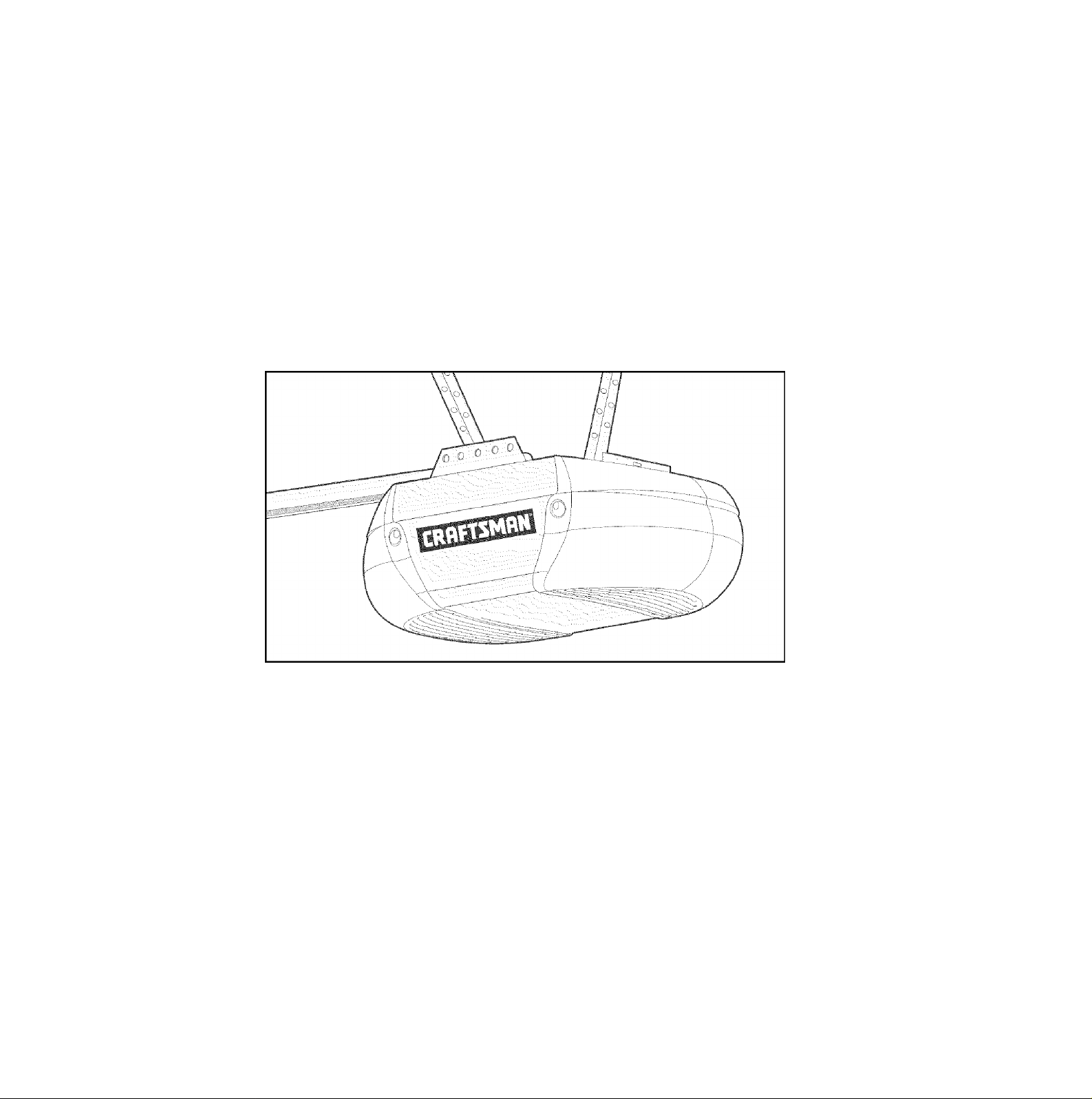
CRRFTSMflN
1/2 HP
315 IVIHz GARAGE DOOR OPENER
ABRIDOR DE PUERTA DE COCHERA DE
For Residential Use Oniy/Sólo para uso residencial
Model/Modelo 139.53993D
IVIHz
Q
W
CO
5
Read and follow all safety rules and
operating instructions before first use
of this product.
Fasten the manual near the garage
door after installation.
Periodic checks of the opener are
required to ensure safe operation.
;(g)
Sears, Roebuck and Co., Hoffman Estates, IL 60179 U.S.A
WWW. s ea rs .CO m/c raftsman
US
Leer y seguir todas las reglas de
seguridad y las instrucciones de
operación antes de usar este
producto por primera vez.
Guardar este manual cerca de la
puerta de la cochera.
Se deben realizar revisiones
periódicas del abridor de puertas
para asegurar su operación segura.
Page 2

TABLE OF CONTENTS
Introduction 2-7
Safety symbol and signal word review
Preparing your garage door
Tools needed ..................................................................3
Planning
Carton inventory
Hardware inventory
......................................................................
..............................................................
........................................................
............................................
............................
4-5
Assembly 8-11
Assemble the rail .........................................................8-9
Fasten the rail to the motor unit and
install the trolley.............................................................10
Attach the rail brackets
.................................................
11
Installation 11-26
Installation safety instructions ......................................11
Determine the header bracket location
Install the header bracket .............................................13
Attach the rail to the header bracket
Install the Protector System®
Position the opener
Hang the opener ...........................................................19
Install the door control ..................................................20
Electrical requirements
Complete safety reversing sensor installation
Install the lights
Attach the emergency release rope and handle
Fasten the door bracket
Connect the door arm to the trolley .........................25-26
......................................................
.................................................
............................................................
.................................
..........................................
........................
.............................
15-17
..............
..........
23-24
12
14
18
21
21
22
22
Adjustment 27-29
2
3
6
7
Adjust the travel limits ...................................................27
Adjust the force .............................................................28
Test the safety reversal system.....................................29
Test the Protector System®
.........................................
29
Operation 30-34
Operation safety instructions.........................................30
Using your garage door opener
Using the wall-mounted door control
To open the door manually
Care of your opener
Having a problem?
Diagnostic chart.............................................................34
......................................................
........................................................
....................................
............................
..........................................
30
31
31
32
33
Programming 35-36
To add or reprogram a hand-held remote control
To erase all codes from motor unit memory .................35
3-Button remotes...........................................................35
To add, reprogram or change a Keyless Entry PIN ... .36
.
35
Repair Parts 37-38
Rail assembly parts ......................................................37
Installation parts
Motor unit assembly parts
............................................................
............................................
37
38
Accessories 39
Warranty 39
INTRODUCTION
Safety Symbol and Signal Word Review
This garage door opener has been designed and tested to offer safe service provided it is installed, operated,
maintained and tested in strict accordance with the instructions and warnings contained in this manual.
ák WARNING
Mechanical
WARNING
Electrical
CAUTION
When you see these Safety Symbols and Signal Words
on the following pages, they will alert you to the
possibility of serious injury or death if you do not
comply with the warnings that accompany them. The
hazard may come from something mechanical or from
electric shock. Read the warnings carefully.
When you see this Signal Word on the following pages, it
will alert you to the possibility of damage to your garage
door and/or the garage door opener if you do not comply
with the cautionary statements that accompany it. Read
them carefully.
Page 3
Preparing your garage door
Before you begin:
• Disable locks.
• Remove any ropes connected to garage door.
• Complete the following test to make sure your
garage door is balanced and is not sticking or binding;
1. Lift the door about halfway as shown. Release the
door. If balanced, it should stay in place, supported
entirely by its springs.
2. Raise and lower the door to see if there is any
binding or sticking.
If your door binds, sticks, or is out of balance, call a
trained door systems technician.
A WARNING
To prevent possible SERIOUS INJURY or DEATH:
• ALWAYS call a trained door systems technician if garage
door binds, sticks, or is out of balance. An unbalanced
garage door may not reverse when required.
• NEVER try to loosen, move or adjust garage door, door
springs, cables, pulleys, brackets or their hardware, all of
which are under EXTREME tension.
• Disable ALL locks and remove ALL ropes connected to
garage door BEFORE installing and operating garage door
opener to avoid entanglement.
CAUTION
To prevent damage to garage door and opener:
• ALWAYS disable locks BEFORE installing and operating the
opener.
• ONLY operate garage door opener at 120V, 60 FIz to avoid
malfunction and damage.
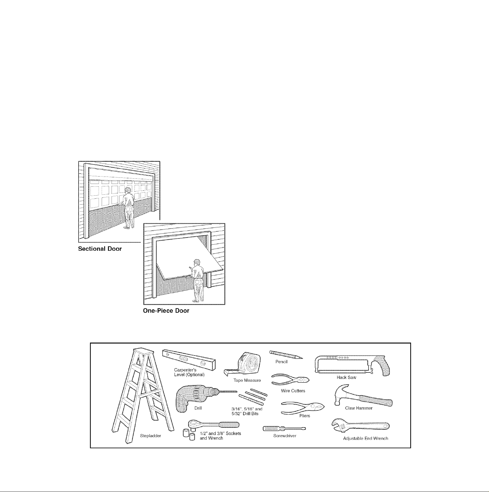
Tools needed
During assembly, installation and adjustment of the
opener, instructions will call for hand tools as illustrated
below.
Page 4
Planning
Identify the type and height of your garage door. Survey
your garage area to see if any of the conditions below
apply to your installation. Additional materials may be
required. You may find it helpful to refer back to this page
and the accompanying illustrations as you proceed with
the installation of your opener.
Depending on your requirements, there are several
installation steps which may call for materials or
hardware not included in the carton.
• Installation Step 1 - Look at the wall or ceiling above
the garage door. The header bracket must be securely
fastened to structural supports.
• Installation Step 4 - Depending upon garage
construction, extension brackets or wood blocks may
be needed to install sensors.
• Installation Step 4 - Alternate floor mounting of the
safety reversing sensor will require hardware not
provided.
• Installation Step 6 - Do you have a finished ceiling in
your garage? If so, a support bracket and additional
fastening hardware may be required.
Do you have an access door in addition to the garage
door? If not, Model 53702 Emergency Key Release is
required. See Accessories page.
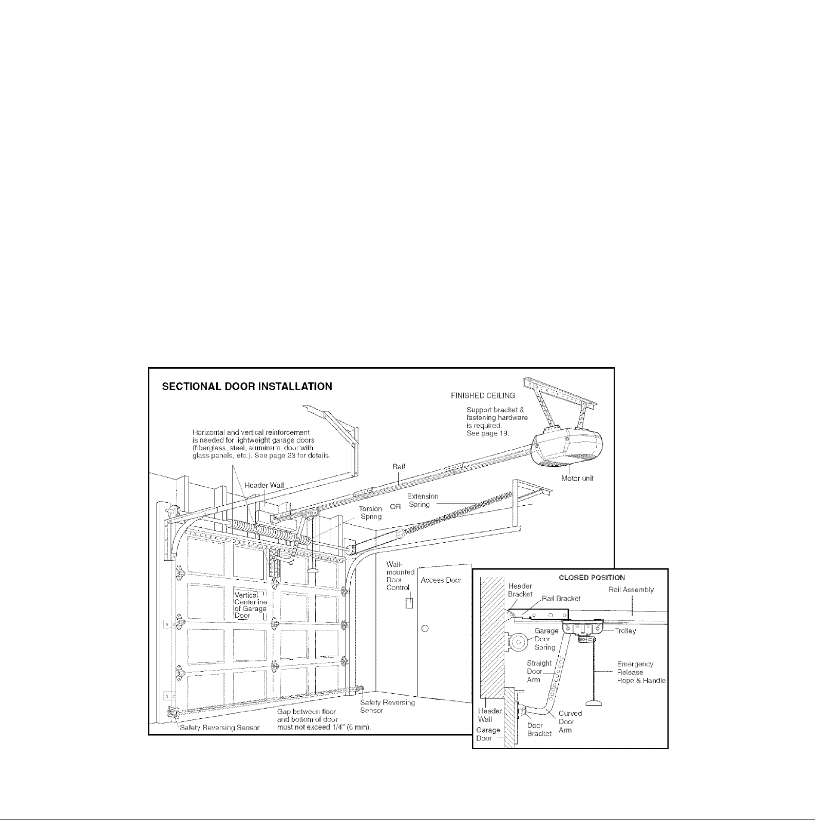
Look at the garage door where it meets the floor. Any
gap between the floor and the bottom of the door must
not exceed 1/4" (6 mm). Otherwise, the safety reversal
system may not work properly. See Adjustment Step 3.
Floor or door should be repaired.
SECTIONAL DOOR INSTALLATIONS
• Do you have a steel, aluminum, fiberglass or glass
panel door? If so, horizontal and vertical reinforcement
is required (Installation Step 12).
• The opener should be installed above the center of the
door. If there is a torsion spring or center bearing plate
in the way of the header bracket, it may be installed
within 4 feet (1.2 m) to the left or right of the door
center. See Installation Steps 1 and 12.
• If your door is more than 7 feet (2.13 m) high, see rail
extension kits listed on Accessories page.
Page 5
Planning (Continued)
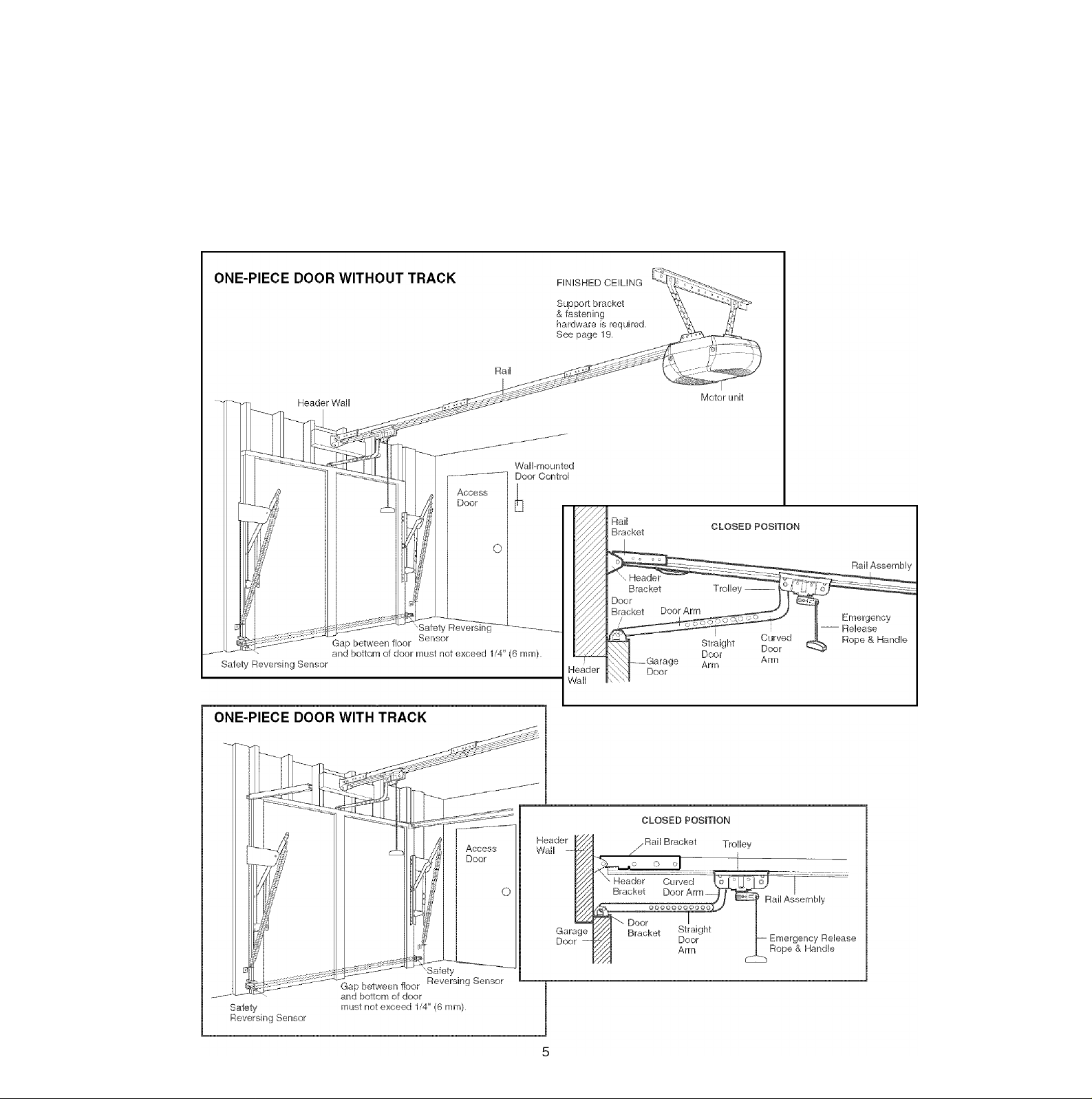
ONE-PIECE DOOR INSTALLATIONS
• Generally, a one-piece door does not require
reinforcement, if your door is lightweight, refer to the
information reiating to sectional doors in Instailation
Step 12.
• Depending on your door’s construction, you may need
additional mounting hardware for the door bracket
(Step 12).
A WARNING
Without a properly working safety reversal system, persons
(particularly small children) could be SERIOUSLY INJURED
or KILLED by a closing garage door.
• The gap between the bottom of the garage door and the
floor MUST NOT exceed 1/4" (6 mm). Otherwise, the safety
reversal system may not work properly.
• The floor or the garage door MUST be repaired to eliminate
the gap.
Page 6
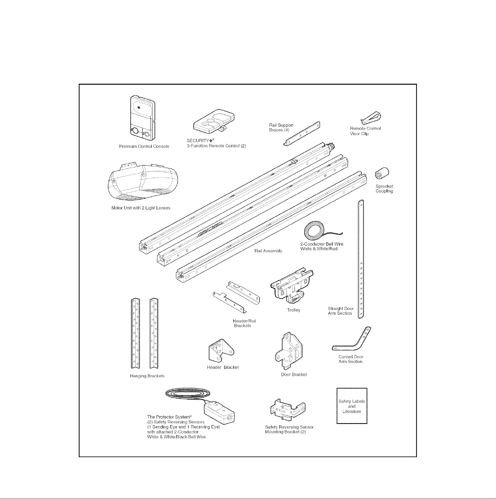
Carton Inventory
Your garage door opener is packaged in one carton which
contains the motor unit and all parts illustrated below.
Accessories will depend on the model purchased. If
anything is missing, carefully check the packing material.
PARTS MAY BE STUCK IN THE FOAM. Hardware for
assembly and installation is shown on the next page.
Save the carton and packing material until installation and
adjustment is complete.
Page 7
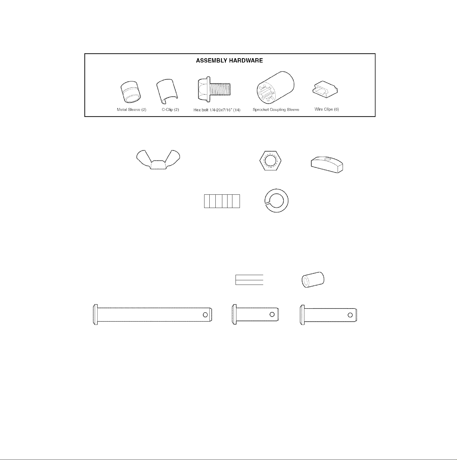
Hardware Inventory
Separate all hardware and group as shown below for the assembly and installation procedures.
INSTALLATION HARDWARE
1)
Carriage Boit
1/4‘-20x1/2‘ (2)
Lag Screw
5/16"-9x1-5/8" (2)
Wing Nut
1/4‘-20 (2)
Lag Screw
5/l‘6“-18x1-7/8" (2)
Carriage Boit
5/16"-18x2-1/2" (2)
Cievis Pin
5/16"x2-3/4" (1)
o
Ring
Fastener (3)
1
Hex Boif
5/16‘-1Sx7/8‘ (4)
1 I
1 1
1 1
i I i i I i i i I i i I n>
Nut 5/16"-18{6) Handle
\
/
Lock Washer 5/16" (6)
Screw
6ABX1-1/4" (2)
Tlwr~
I.Trrmrz
Drywail Anchors (2)
h
1
Clevis Pin
5/16"x1‘ (1)
Insulated
Staples (30)
I
I I I I I
Screw 6-32x1 “ (2)
Spacer
Clevis Pin
5/16"x1-1/4" (1)
Rope
Page 8
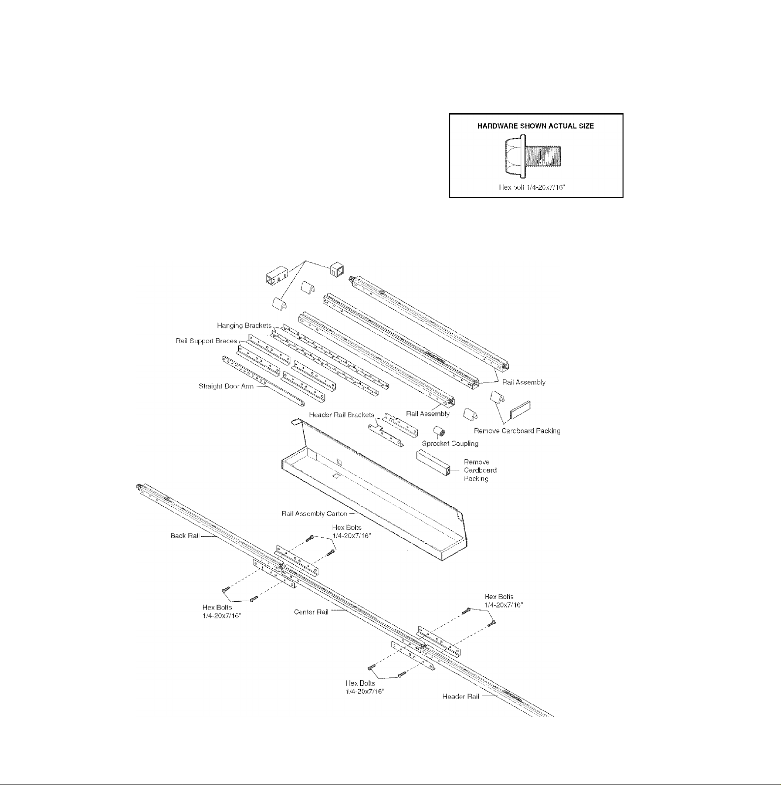
ASSEMBLY STEP 1
Assemble the Rail
To avoid installation difficulties, do not run the garage door opener until instructed to do so.
1 .Open the rail carton and remove the contents onto a
level work surface. Keep it clean and free of debris
while you are working.
2. Identify the rail sections and orient the sections on a
flat surface as shown. The back rail has a black gear
on one end. The header rail has a black plastic rack
inside the rail on the screw. The remaining section is
the center rail.
NOTE: Use caution when handling the center rail
section. The screw can slip out If the section is tipped up
too far.
Remove Cardboard Packing
CAUTION
To prevent INJURY from pinching, keep hands and fingers
away from the joints while assembling the rail.
Page 9
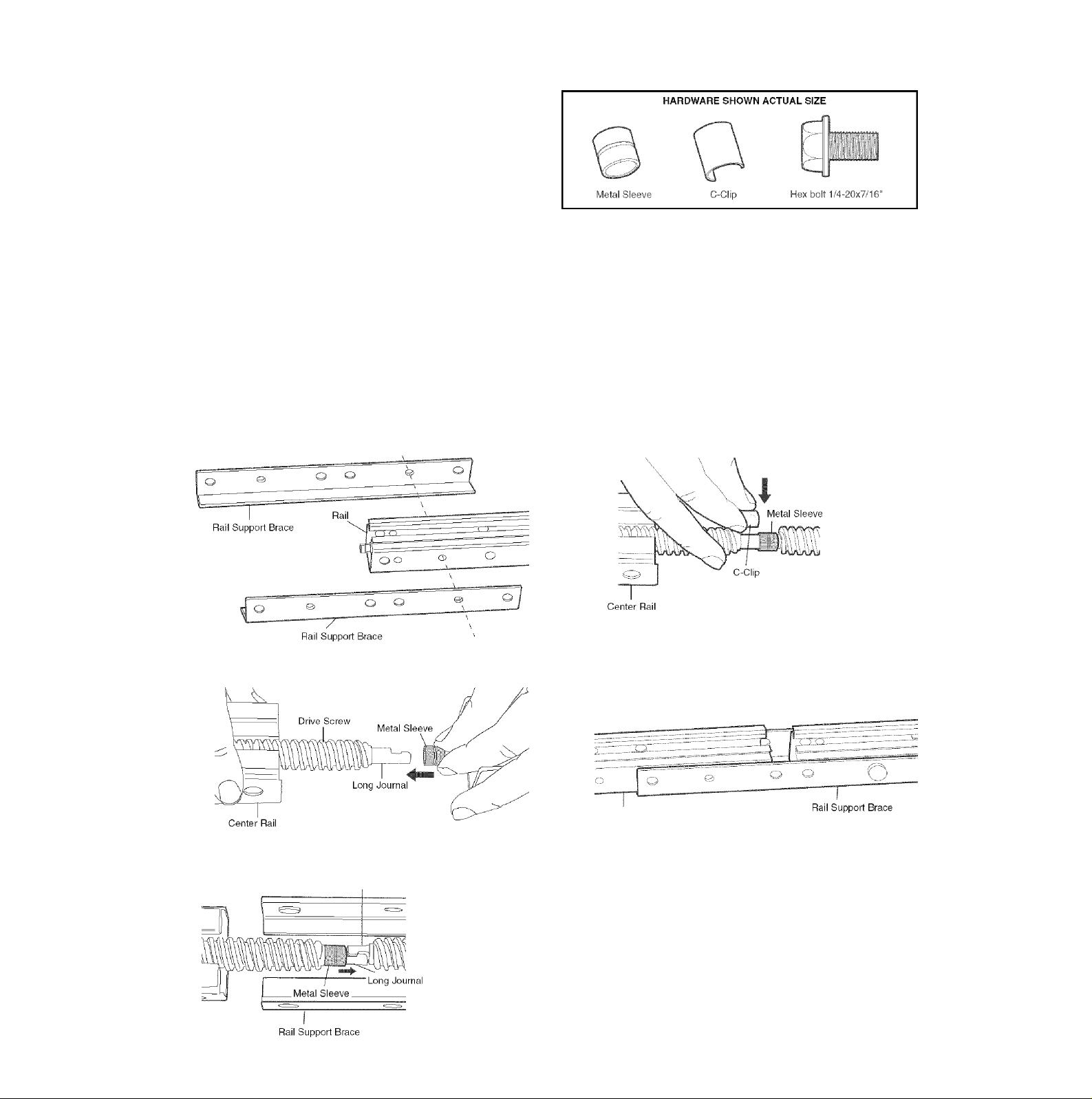
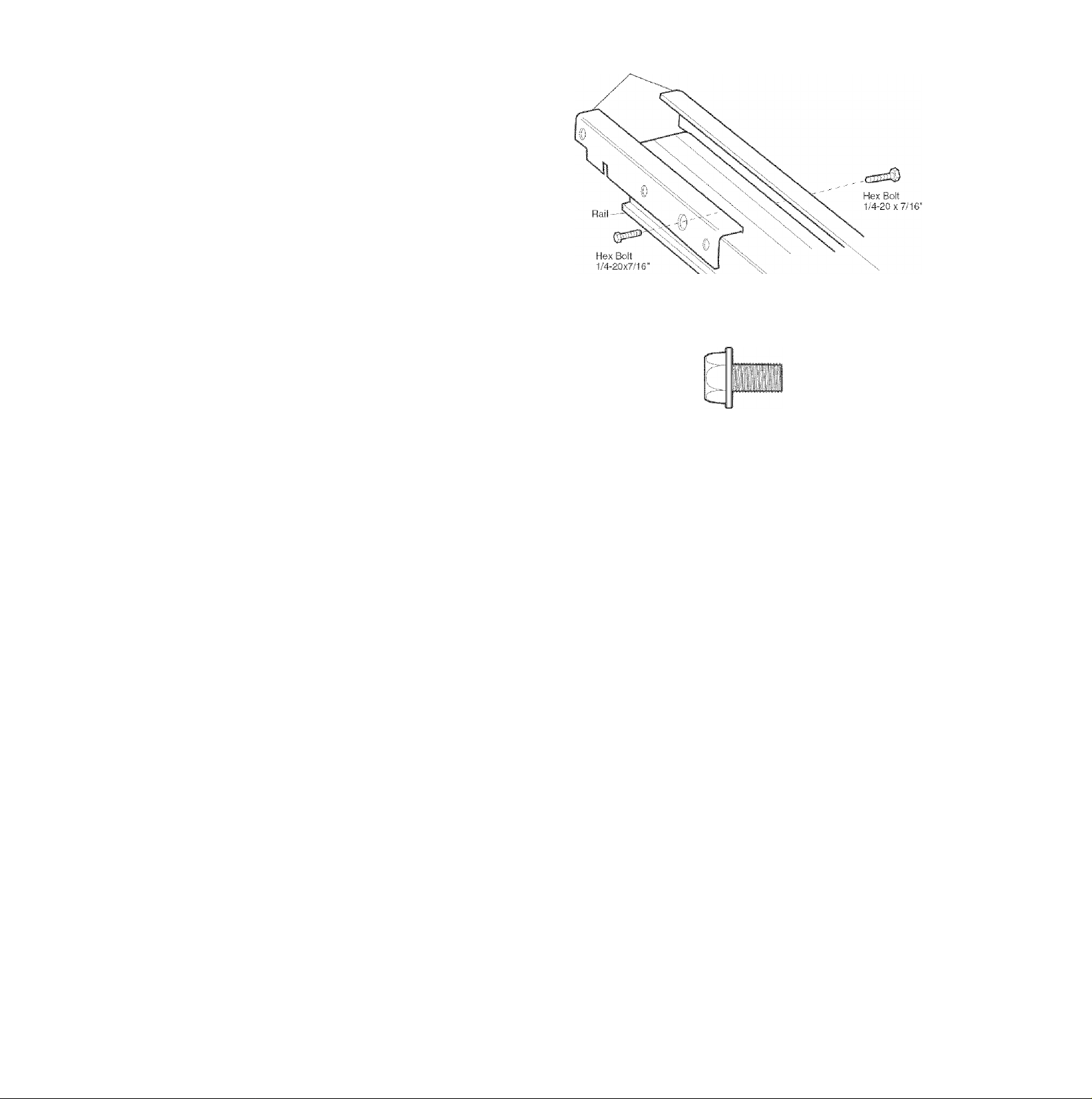
Assemble the Rail (continued)
3. Attach rail support braces to the back rail. Loosely
insert 1/4-20x7/16" hex bolts into the aligned holes of
the end rail and rail support brace (Figure 1). Do not
finger tighten.
4. Extend the drive screw a few inches from the center
rail, and slide the sleeve onto the long journal
(Figure 2).
5. Interlock the long and short journal of the center and
back rails. Slide the sleeve over the journal connection
(Figure 3).
6. Place the c-clip onto the long journal shaft (center rail)
to ensure that the sleeve does not slide (Figure 4).
7. Slide the center rail so that the center rail and rail
brace holes are aligned (Figure 5). Secure with bolts.
8. Tighten all hex bolts.
9. Repeat steps 3-8 for header section.
Figure 1
Figure 2
Figure 4
Figure 5
Center Rail
Figure 3
Short Journal
Page 10
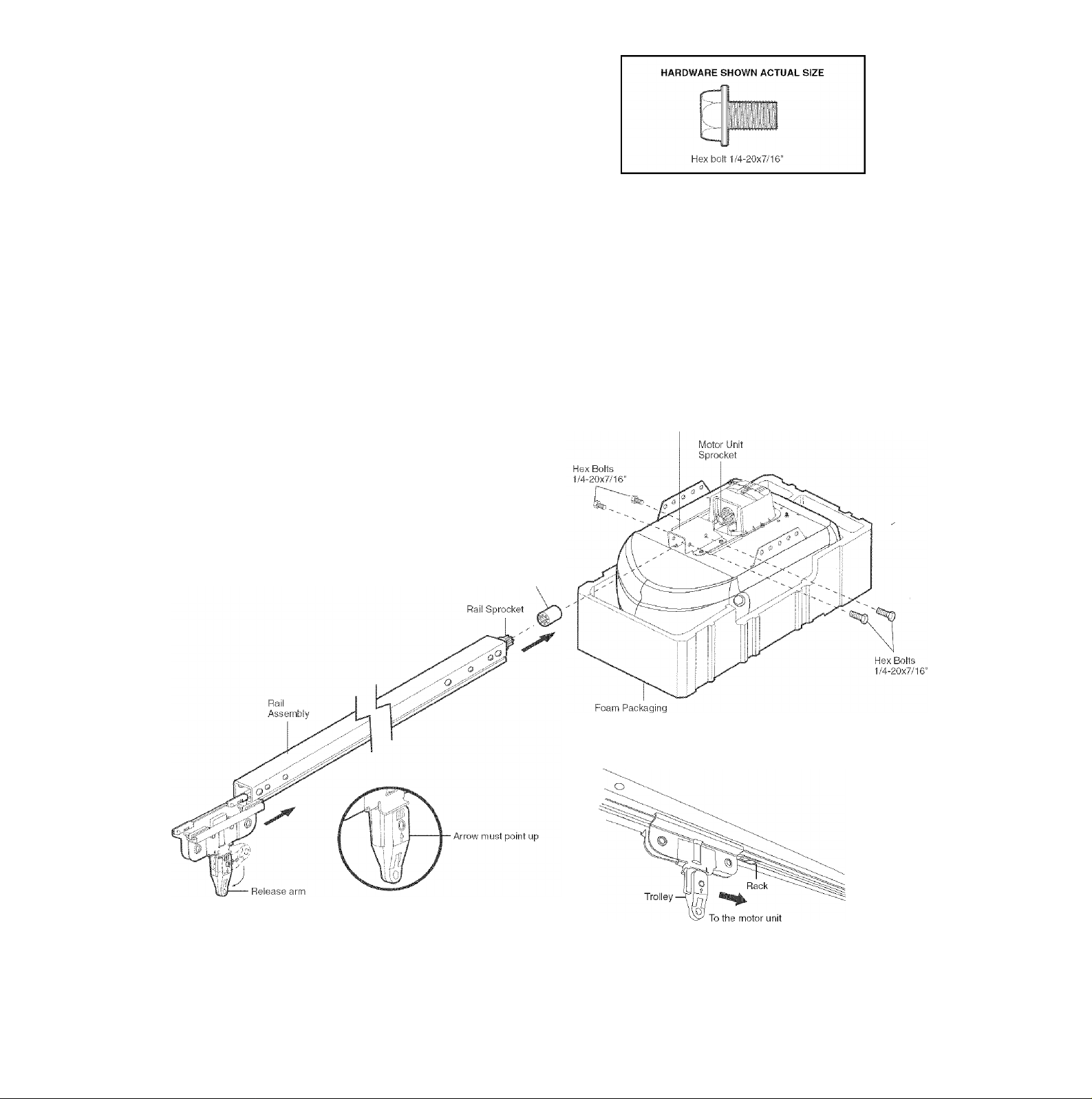
ASSEMBLY STEP 2
Fasten the Rail to the Motor Unit and
Install the Trolley
NOTE: To aid in assembly and instai/ation, replace the
foam packing around the motor unit. Remove it after
Installation Step 4.
1 .Working on a level surface, align the rail assembly with
the motor unit, as shown.
2. Slip the coupling over the rail sprocket.
3. Slide the rail through the motor unit bracket until the
coupling fits securely over the motor unit sprocket.
4. Align the four bolt holes in the rail with those in the
motor unit bracket. Insert four 1/4"-20x7/16" hex bolts.
Tighten securely with a 3/8" socket wrench.
5. Disengage trolley by turning the release arm down
(arrow pointing up). Slide trolley onto and along the
bottom of the rail until it aligns with the rack. Turn
release arm up (arrow pointing away from motor unit.
This will join the rack and the trolley.
Motor Unit
Bracket
Coupling
10
Page 11
ASSEMBLY STEP 3
Attach the Rail Brackets
• Align rail brackets to end of rail assembly, as shown.
• Insert two 1/4"-20x7/16" hex bolts. Tighten securely
with a 3/8" socket.
You have now finished assembiing your garage door
opener. Piease read the following warnings before
proceeding to the installation section.
Rail Brackets
HARDWARE SHOWN ACTUAL SIZE
Hex bolt 1/4-20x7/16"
INSTALLATION
IMPORTANT INSTALLATION INSTRUCTIONS
A £k WARNING
To reduce the risk of SEVERE INJURY or DEATH:
. READ AND FOLLOW ALL INSTALLATION WARNINGS AND
INSTRUCTIONS.
. Install garage door opener only on properly balanced and
lubricated garage door. An improperly balanced door may
not reverse when required and could result in SEVERE
INJURY or DEATH.
. ALL repairs to cables, spring assemblies and other
hardware MUST be made by a trained door systems
technician BEFORE installing opener.
. Disable ALL locks and remove all ropes connected to
garage door BEFORE Installing opener to avoid
entanglement.
, Install garage door opener 7 feet (2.13 m) or more above
floor.
. Mount emergency release handle 6 feet (1.83 m) above
floor.
. NEVER connect garage door opener to power source until
instructed to do so.
8. NEVER wear watches, rings or loose clothing while
installing or servicing opener. They could be caught in
garage door or opener mechanisms.
9. Install wall-mounted garage door control:
• within sight of the garage door.
• out of reach of children at minimum height of 5 feet
(1.5 m).
• away from ALL moving parts of the door.
10. Place entrapment warning label on wall next to garage
door control.
11. Place manual release/safety reverse test label in plain
view on inside of garage door.
12. Upon completion of installation, test safety reversal
system. Door MUST reverse on contact with a 1-1/2"
(T8 cm) high object (or a 2x4 laid flat) on the floor.
11
Page 12
INSTALLATION STEP 1
Determine the Header Bracket
Location
A WARNING
To prevent possible SERIOUS INJURY or DEATH:
• Header bracket MUST be RIGIDLY fastened to structural
support on header wall or ceiling, otherwise garage door
might not reverse when required. DO NOT install header
bracket over dry wall.
• Concrete anchors MUST be used if mounting header
bracket or 2x4 into masonry.
• NEVER try to loosen, move or adjust garage door, springs,
cables, pulleys, brackets, or their hardware, all of which are
under EXTREME tension.
• ALWAYS call a trained door systems technician if garage
door binds, sticks, or is out of balance. An unbalanced
garage door might not reverse when required.
Installation procedures vary according to garage door
types. Follow the instructions which apply to your door.
1 .Close the door and mark the inside vertical centerline
of the garage door.
2. Extend the line onto the header wall above the door.
You can fasten the header bracket within 4 feet
(1.22 m) of the left or right of the door center only
if a torsion spring or center bearing plate is in the
way; or you can attach it to the ceiling
(see page 13) when clearance is minimal. (It may
be mounted on the wall upside down if necessary,
to gain approximately 1/2" (1 cm).
If you need to install the header bracket on a 2x4
(on wall or ceiling), use lag screws (not provided)
to securely fasten the 2x4 to structural supports as
shown here and on page 13.
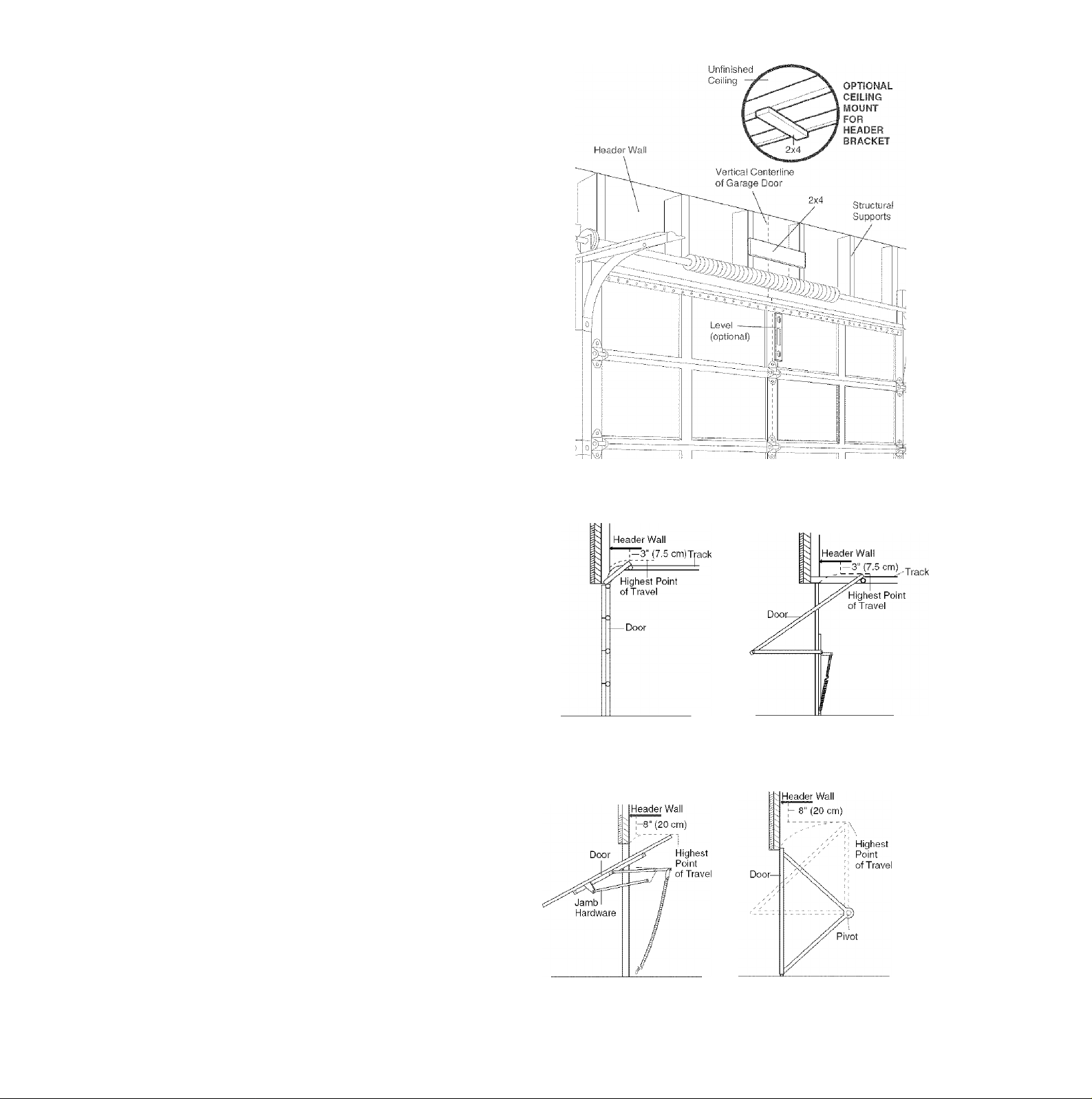
3.0pen your door to the highest point of travel as shown.
Draw an intersecting horizontal line on the header wall
above the high point:
• 3" (7.5 cm) above the high point for sectional door
and one-piece door with track.
• 8" (20 cm) above the high point for one-piece door
without track.
This height will provide travel clearance for the top
edge of the door.
NOTE: If the total number of inches exceeds the
height available in your garage, use the maximum
height possible, or refer to page 13 for ceiling
installation.
Sectional door with curved track
One-piece door with horizontal track
One-piece door without track:
jamb hardware
12
One-piece door without track:
pivot hardware
Page 13
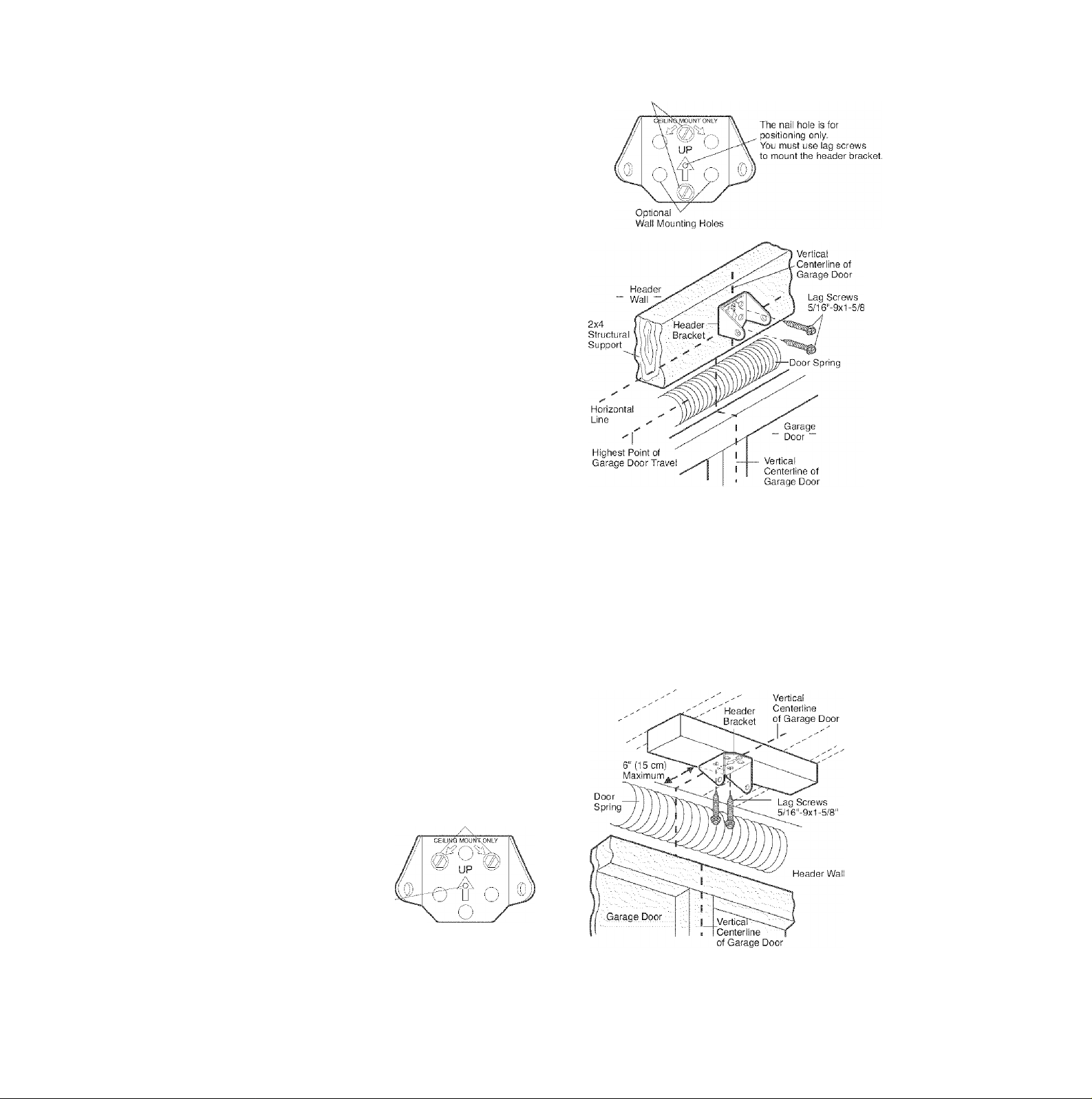
INSTALLATION STEP 2
Install the Header Bracket
You can attach the header bracket either to the wall
above the garage door, or to the ceiling. Follow the
instructions which will work best for your particular
requirements. Do not install the header bracket over
drywall. If installing into masonry, use concrete
anchors (not provided).
WALL HEADER BRACKET INSTALLATION
• Center the bracket on the vertical centerline with the
bottom edge of the bracket on the horizontal line as
shown (with the arrow pointing toward the ceiling).
• Mark the vertical set of bracket holes. Drill 3/16" pilot
holes and fasten the bracket securely to a structural
support with the hardware provided.
HARDWARE SHOWN ACTUAL SIZE
[i>
Lag Screw
5/16"-9x1-5/8"
Wall Mounting Holes
CEILING HEADER BRACKET INSTALLATION
• Extend the vertical centerline onto the ceiling as shown.
• Center the bracket on the vertical mark, no more than
6" (15 cm) from the wall. Make sure the arrow is
pointing toward the wall. The bracket can be mounted
flush against the ceiling when clearance is minimal.
• Mark the side holes. Drill 3/16" pilot holes and fasten
bracket securely to a structural support with the
hardware provided.
Ceiling Mounting Holes
The nail hole Is for
positioning only. You must use lag screws
to mount the header bracket.
- Finished Ceiiing -
13
Page 14
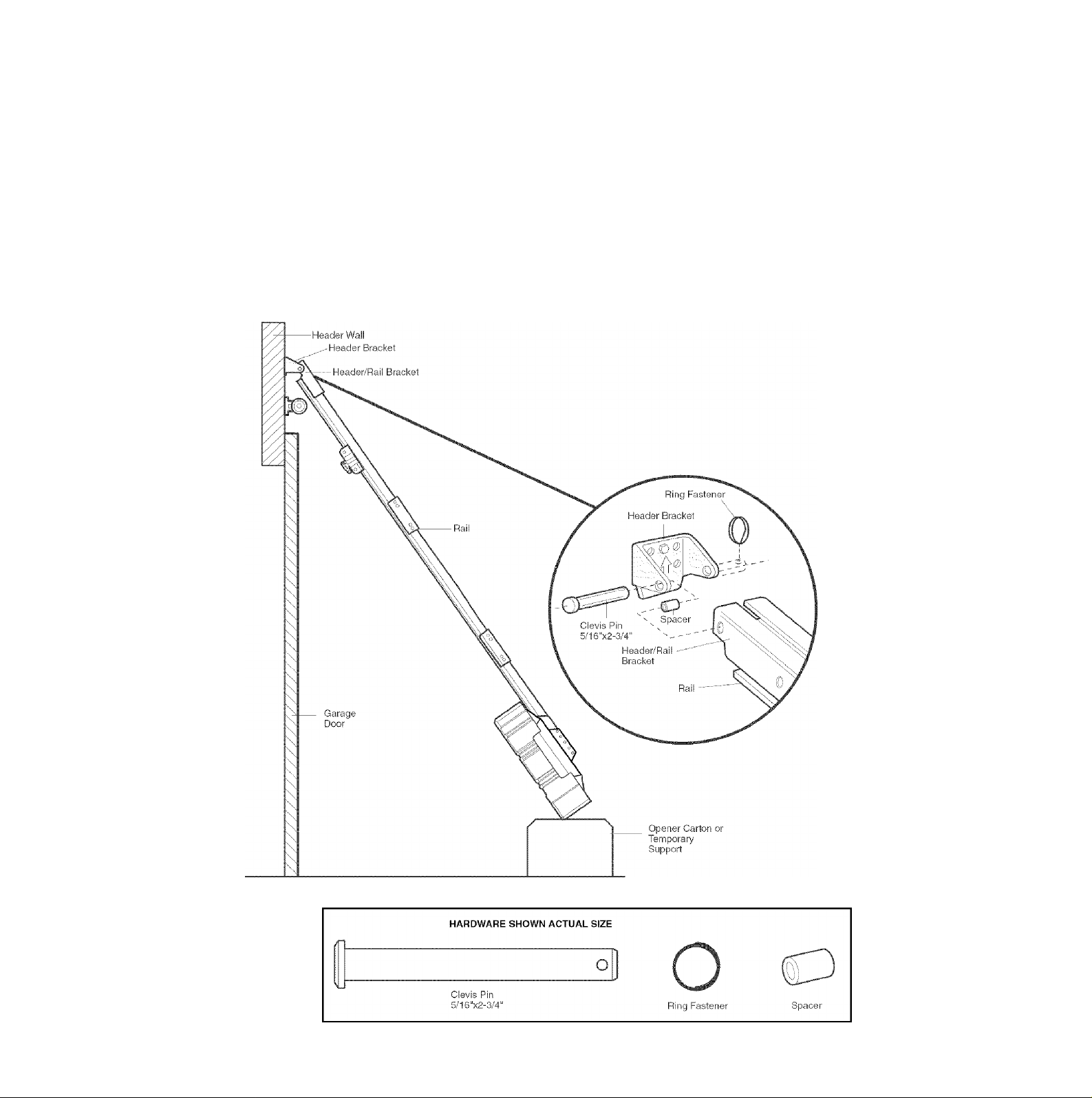
INSTALLATION STEP 3
Attach the Rail to the Header Bracket
• Position the opener on the garage floor below the
header bracket. Use packing material as a protective
base. NOTE: If the door spring is in the way you’il
need heip. Have someone hold the opener securely on
a temporary support to allow the rail to clear the
spring.
• Position the header/rall bracket against the header
bracket.
• Align the bracket holes and join with a clevis pin
5/16"x2-3/4" as shown. Spacer can be installed on
either side of rail.
• Insert a ring fastener to secure.
14
Page 15
INSTALLATION STEP 4
Install The Protector System^
The safety reversing sensor must be connected and
aligned correctly before the garage door opener will
move in the down direction.
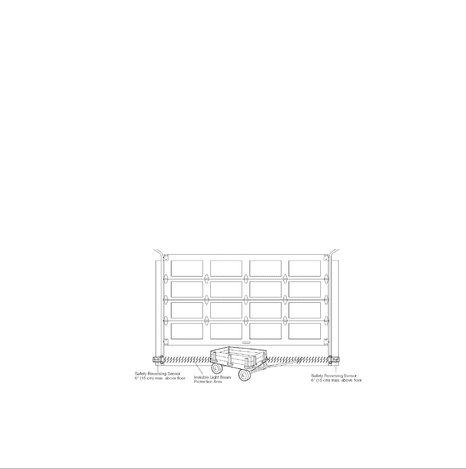
IMPORTANT INFORMATION ABOUT THE SAFETY REVERSING SENSOR
When properly connected and aligned, the sensor will
detect an obstacle in the path of its electronic beam. The
sending eye (with an amber indicator light) transmits an
invisible light beam to the receiving eye (with a green
indicator light). If an obstruction breaks the light beam
while the door is closing, the door will stop and reverse
to full open position, and the opener lights will flash
10 times.
The units must be installed inside the garage so that the
sending and receiving eyes face each other across the
door, no more than 6" (15 cm) above the floor. Either can
be installed on the left or right of the door as long as the
sun never shines directly into the receiving eye lens.
The mounting brackets are designed to clip onto the
track of sectional garage doors without additional
hardware.
ik WARNING
Be sure pov.'er is not connected to the garage door opener
BEFORE installing the safety reversing sensor.
To prevent SERIOUS INJURY or DEATH from a closing
garage door:
• Correctly connect and align the safety reversing sensor.
This required safety device MUST NOT be disabled.
• Install the safety reversing sensor so beam is NO HIGHER
than 6" (15 cm) above garage floor.
If it is necessary to mount the units on the wall, the
brackets must be securely fastened to a solid surface
such as the wall framing. Extension brackets (see
accessories) are available if needed. If installing in
masonry construction, add a piece of wood at each
location to avoid drilling extra holes in masonry if
repositioning is necessary.
The invisible light beam path must be unobstructed. No
part of the garage door (or door tracks, springs, hinges,
rollers or other hardware) may interrupt the beam while
the door is closing.
Facing the door from inside the garage
15
Page 16
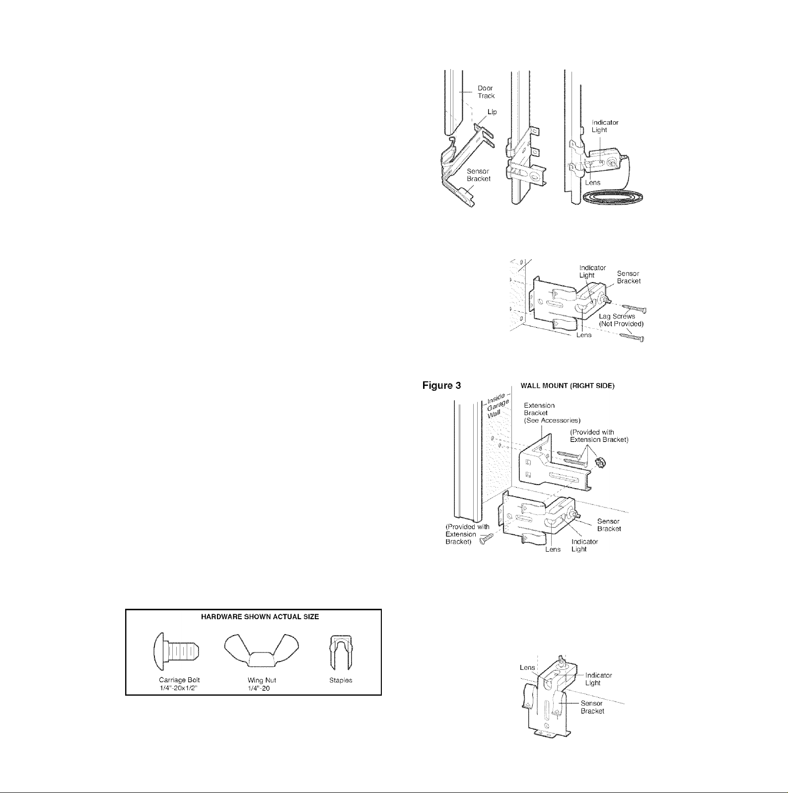
INSTALLING THE BRACKETS
Be sure power to the opener is disconnected. Install
and align the brackets so the sensors will face each
other across the garage door, with the beam no higher
than 6" (15 cm) above the floor. They may be Installed in
one of three ways, as follows.
Garage door track installation (preferred):
• Slip the curved arms over the rounded edge of each
door track, with the curved arms facing the door. Snap
into place against the side of the track. It should lie
flush, with the lip hugging the back edge of the track,
as shown In Figure 1.
If your door track will not support the bracket securely,
wall installation is recommended.
Wall installation (Figure 2 & 3):
• Place the bracket against the wall with curved arms
facing the door. Be sure there is enough clearance for
the sensor beam to be unobstructed.
• If additional depth is needed, an extension bracket
(See Accessories) or wood blocks can be used.
• Use bracket mounting holes as a template to locate
and drill (2) 3/16" diameter pilot holes on the wall at
each side of the door, no higher than 6" (15 cm) above
the floor.
• Attach brackets to wall with lag screws (Not provided).
• If using extension brackets or wood blocks, adjust right
and left assemblies to the same distance out from the
mounting surface. Make sure all door hardware
obstructions are cleared.
Floor installation (Figure 4):
• Use wood blocks or extension brackets
(See Accessories) to elevate sensor brackets so the
lenses will be no higher than 6" (15 cm) above
the floor.
• Carefully measure and place right and left assemblies
at the same distance out from the wall. Be sure all
door hardware obstructions are cleared.
• Fasten to the floor with concrete anchors as shown.
Figure 1 door track mount (right side)
WALL MOUNT (RIGHT SIDE)
Figure 2
W»" -
Fasten Wood Block to Wall with
^Lag Screws (Not Provided)
16
Figure 4
FLOOR MOUNT (RIGHT SIDE)
■* Attach with
Concrete Anchors
(Not Provided)
Page 17
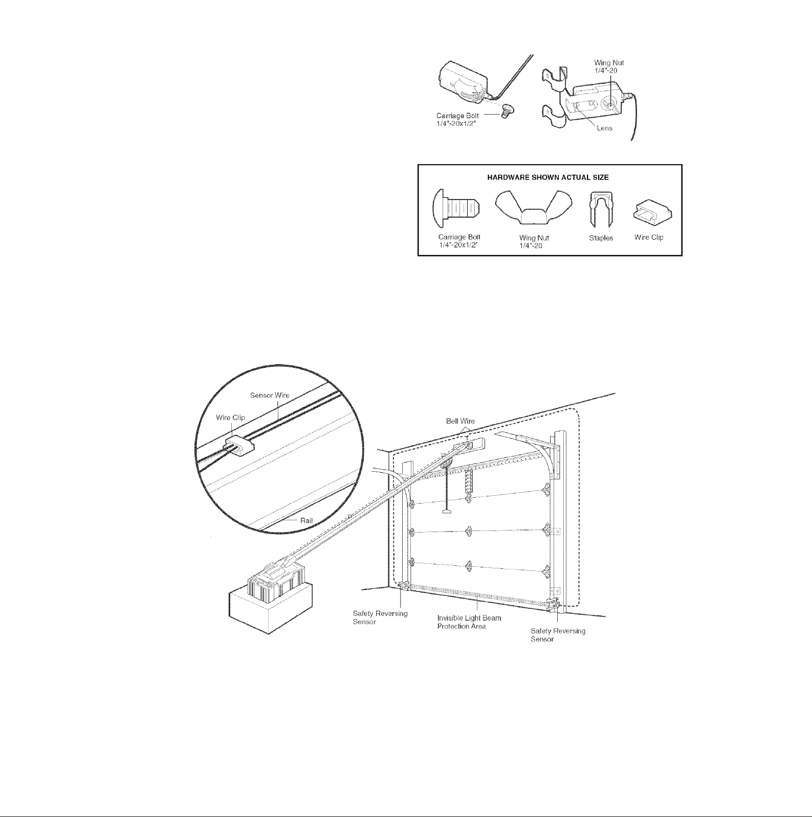
MOUNTING AND WIRING THE SAFETY SENSORS
• Slide a 1/4"-20x1/2" carriage bolt head Into the slot on
each sensor. Use wing nuts to fasten sensors to
brackets, with lenses pointing toward each other
across the door. Be sure the lens Is not obstructed by
a bracket extension (Figure 5).
• Finger tighten the wing nuts.
Recommended Wire Routing
1. Using insulated staples, run the wires from both
sensors to the rail at the door header (Figure 6).
2. Run the wires through wire clip at the top of the rails.
NOTE: If your access door is near the garage door,
you may choose to install the door control at this time
and run the door control wire along the rail with the
sensor wires. If you choose this option, follow
instructions 1 -3 on page 20.
Figure 5
Figure 6
17
Page 18
INSTALLATION STEP 5
Position the Opener
Follow instructions which apply to your door type as
illustrated.
SECTIONAL DOOR OR ONE-PIECE DOOR WITH
TRACK
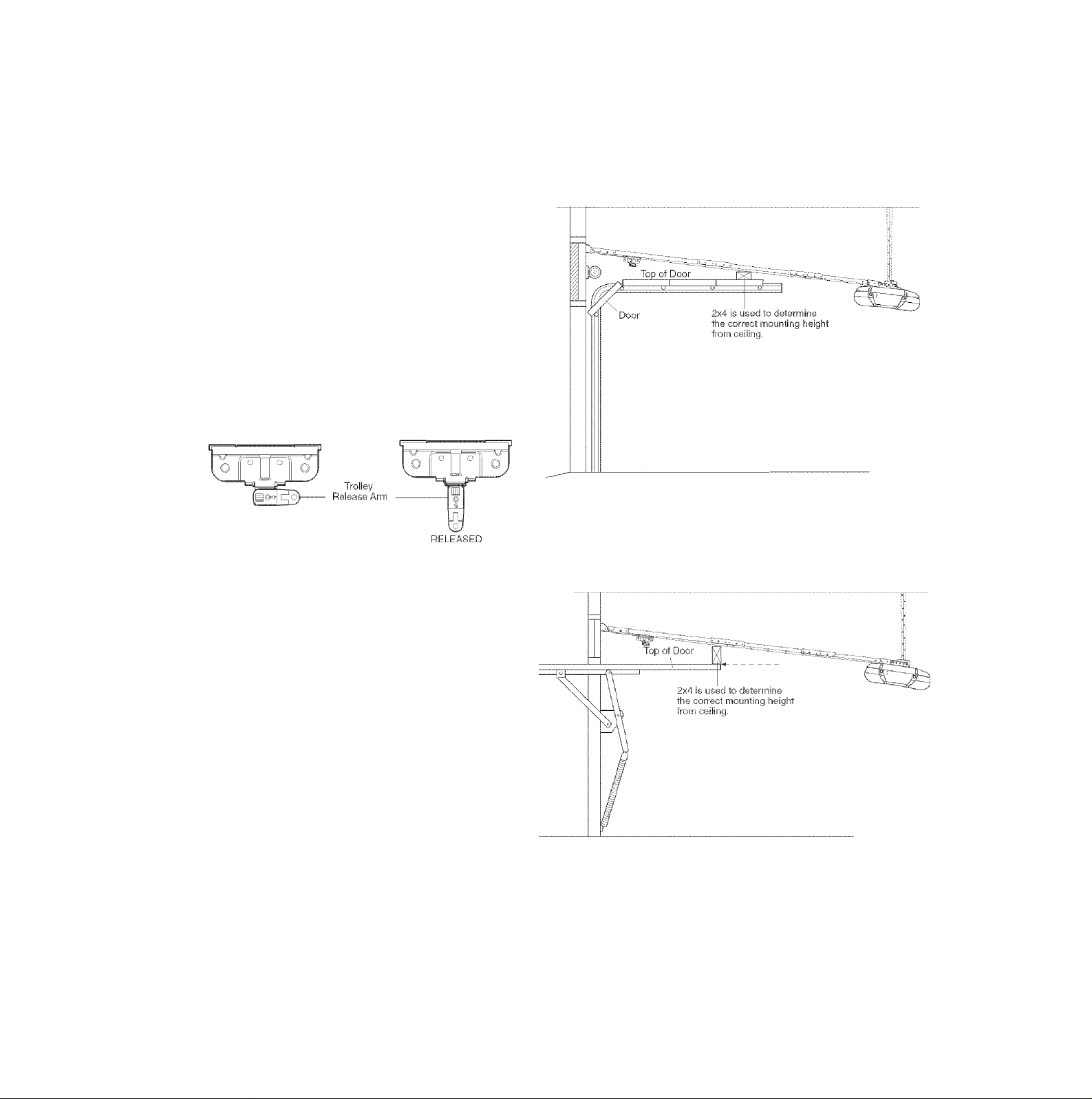
A 2x4 laid flat is convenient for setting an ideal door-to-
rail distance.
• Remove foam packaging.
• Raise the opener onto a stepladder. You will need help
at this point if the ladder is not tall enough.
• Open the door all the way and place a 2x4 laid flat on
the top section beneath the rail.
• If the top section or panel hits the trolley when you
raise the door, pull down on the trolley release arm
to disconnect inner and outer sections. Slide the outer
trolley toward the motor unit. The trolley can remain
disconnected until Installation Step 13 is completed.
CAUTION
To prevent damage to garage door, rest garage door opener
rail on 2x4 placed on top section of door.
ENGAGED
ONE-PIECE DOOR WITHOUT TRACK
A 2x4 on its side is convenient for setting an ideal doorto-rail distance.
• Remove foam packaging.
• Raise the opener onto a stepladder. You will need help
at this point if the ladder is not tall enough.
• Open the door all the way and place a 2x4 on its side
on the top section of the door beneath the rail.
• The top of the door should be level with the top of the
motor unit. Do not position the opener more than 4"
(10 cm) above this point.
18
Page 19
INSTALLATION STEP 6
Hang the Opener
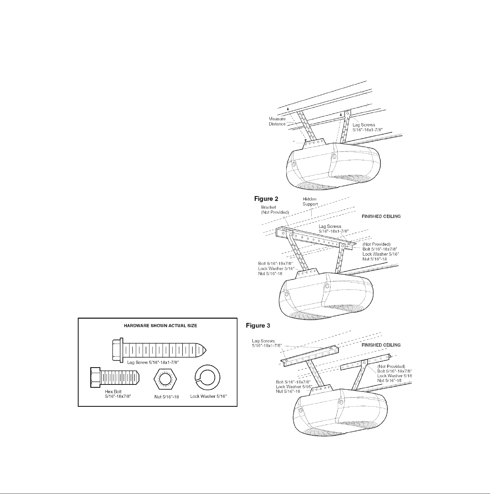
Three representative installations are shown. Yours may
be different. Hanging brackets should be angled
(Figure 1) to provide rigid support. On finished ceilings
(Figure 2 and Figure 3), attach a sturdy metal bracket to
structural supports before installing the opener. This
bracket and fastening hardware are not provided.
1. Measure the distance from each side of the motor unit
to the structural support.
2. Cut both pieces of the hanging bracket to required
lengths.
3. Drill 3/16" pilot holes in the structural supports.
4. Attach one end of each bracket to a support with
5/16"-18x1-7/8" lag screws.
5. Fasten the opener to the hanging brackets with 5/16"18x7/8" hex bolts, lock washers and nuts.
6. Check to make sure the rail is centered over the door
(or in line with the header bracket if the bracket is not
centered above the door).
7. Remove the 2x4. Cperate the door manually. If the
door hits the rail, raise the header bracket.
NOTE: DO NOT connect power to opener at this time.
A WARNING
To avoid possible SERIOUS INJURY from a falling garage
door opener, fasten it SECURELY to structural supports of
the garage. Concrete anchors MUST be used if installing any
brackets into masonry.
Figure 1
Bolt 5/16“-18x7/8"
Lock Washer 5/16
Nut 5/16“-18
structural
/ Supports
19
Page 20
INSTALLATION STEP 7
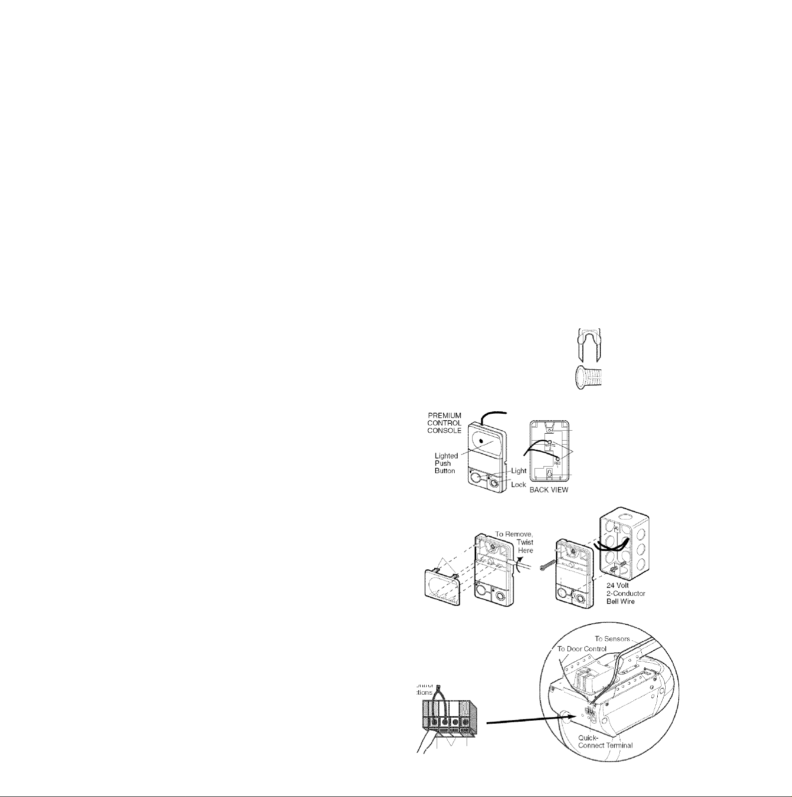
Install the Door Control
Locate door control within sight of door, at a minimum
height of 5 feet (1.52 m) where smali children cannot
reach, away from moving parts of door and door
hardware. If installing into drywall, drill 5/32" holes and
use the anchors provided. For pre-wired installations
(as in new home construction), it may be mounted to a
single gang box (Figure 2).
1. Strip 7/16" (11 mm) of insulation from one end of bell
wire and connect to the two screw terminals on back of
door control by color; white wire to 2 and white/red
wire to the 1.
2. Remove cover by gently prying at slot in side of the
cover with a small flat head screwdriver. Fasten with
6ABx1-1/4" self-tapping screws (drywall installation) or
6-32x1" machine screws (into gang box) as follows:
• Drill and install bottom screw, allowing 1/8" (3 mm) to
protrude above wall surface.
• Position bottom of door control on screw head and
slide down to secure. Adjust screw for snug fit.
• Drill and install top screw with care to avoid cracking
plastic housing. Do not over tighten.
• Insert top tabs and snap on cover.
3. (Standard installation only) Run bell wire up wall
and across ceiling to motor unit. Use insulated staples
to secure wire in several places. Do not pierce wire
with a staple, creating a short or open circuit. If your
access door is near the garage door, you may run this
wire with the Safety Reversing Sensor wires along the
top of the rail. See page 17.
4. Insert all wires through the opening on top of motor
unit above the terminal block on the back panel
(Figure 3).
5. Strip 7/16" (11 mm) of insulation from each set of
wires. Insert door control wire into quick-connect
terminals by color: white wire to white, white/red wire
to red.
Separate white and white/black wires sufficiently to
connect to the opener quick-connect terminals. Twist
like colored wires together. Insert wires into quickconnect holes: white to white and white/black to grey.
NOTE: When connecting multiple door controls to the
opener, twist same color wires together. Insert wires into
quick-connect holes: white to white and red/white to red.
6. Use tacks or staples to permanently attach entrapment
warning label to wall near door control, and manual
release/safety reverse test label in a prominent
location on inside of garage door.
NOTE: DO NOT connect the power and operate the
opener at this time. The trolley will travel to the full open
position but will not return to the close position until the
sensor beam is connected and
properly aligned.
■C7/18" {11m
Strip wire 7/16" (11 mm)
Aik WARNING
To prevent possible SERIOUS INJURY or DEATH from
electrocution:
• Be sure power is not connected BEFORE installing door
control.
• Connect ONLY to 24 VOLT low voltage wires.
To prevent possible SERIOUS INJURY or DEATH from a
closing garage door:
• Install door control within sight of garage door, out of reach
of children at a minimum height of 5 feet
(1.5 m), and away from all moving parts of door.
• NEVER permit children to operate or play with door control
push buttons or remote control transmitters.
• Activate door ONLY when it can be seen clearly, is properly
adjusted, and there are no obstructions to door travel.
• ALWAYS keep garage door in sight until completely closed.
NEVER permit anyone to cross path of closing garage door.
Outside Keylock Accessory Connections
To opener quick-connect terminals: white to white;
white/red to red.
HARDWARE SHOWN ACTUAL SIZE
Screw 6ABx1-1/4”
Control Panel (std installation)
iiiiiiiiiiiiiii
&
Screw 6-32x1"
Control Panel (pre-wIred)
Figure 1
REMOVE & REPLACE COVER
To Replace,
Insert Top
Tabs First ,
Figure 3 Wiring to Terminal Block
Strip 7/16" (11 mm) of insulation from each wire
Insert wires through opening on top of motor unit
above terminal block, then into quick-connect
terminals.
To release wire, push in tab
with screwdriver tip
n>
Drywall Anchors
- Top
Mounting Hole
Terminal
Screws
Bottom
Mounting Hole
Figure 2
PRE-WIRED
INSTALLATION
Insulated
Staples
20
Red White Grey
Page 21
INSTALLATION STEP 8
Electrical Requirements
To avoid installation difficulties, do not run the opener until Step 11 below.
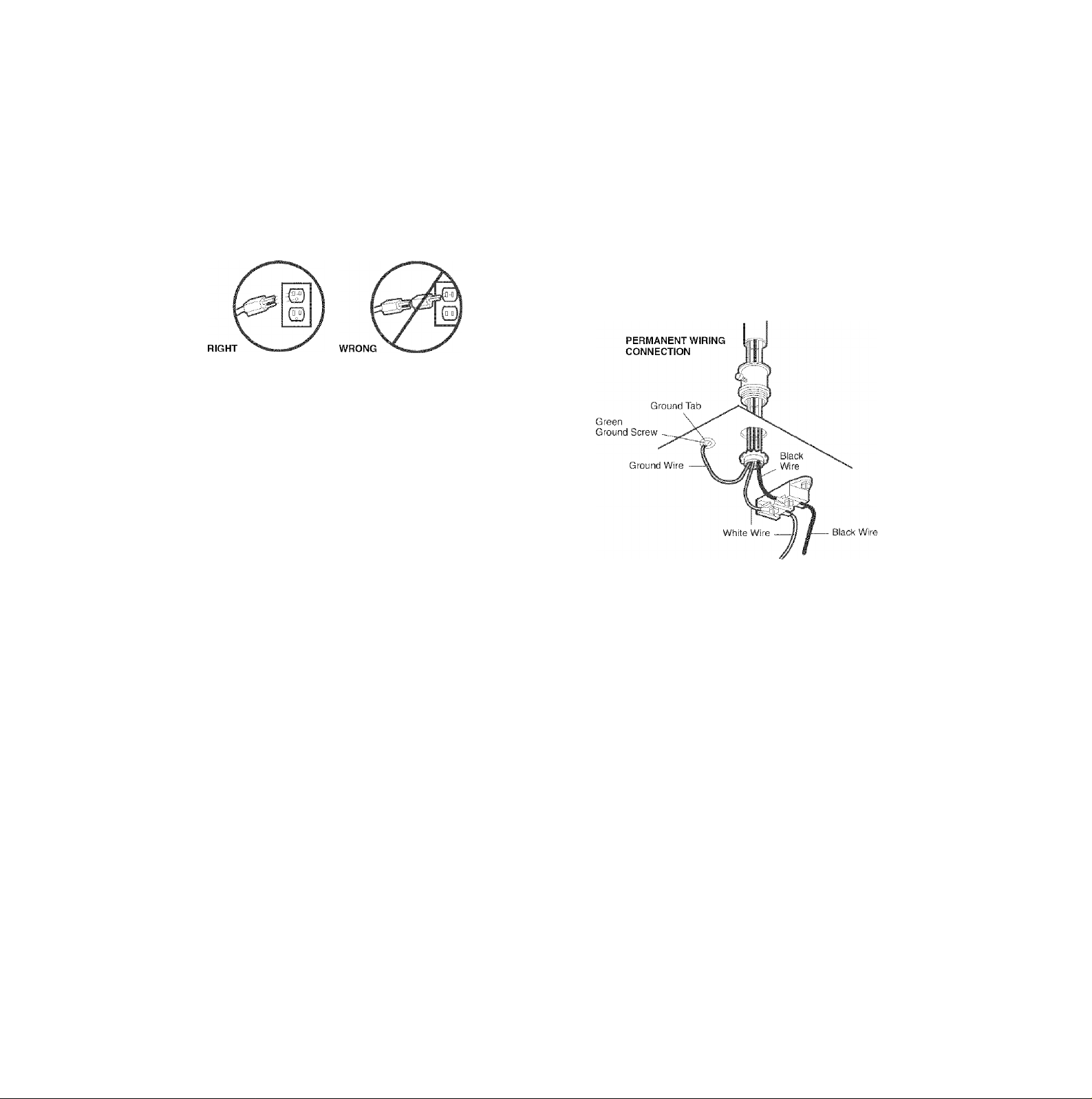
To reduce the risk of electric shock, your garage door
opener has a grounding type plug with a third grounding
pin. This plug will only fit into a grounding type outlet. If
the plug doesn’t fit into the outlet you have, contact a
qualified electrician to install the proper outlet.
If permanent wiring is required by your local code, refer to the following procedure.
To make a permanent connection through the 7/8" hole
in the top of the motor unit:
• Remove the motor unit cover screws and set the cover
aside.
• Remove the attached 3-prong cord.
• Connect the black (line) wire to the screw on the brass
terminal; the white (neutral) wire to the screw on the
silver terminal; and the ground wire to the green
ground screw. The opener must be grounded.
• Reinstall the cover.
To avoid installation difficulties, do not run the
opener at this time.
A WARNING
To prevent possible SERIOUS INJURY or DEATH from
electrocution or fire:
• Be sure power is not connected to the opener, and
disconnect power to circuit BEFORE removing cover to
establish permanent wiring connection.
• Garage door installation and wiring MUST be in compliance
with ALL local electrical and building codes.
• NEVER use an extension cord, 2-wire adapter, or change
plug in ANY way to make it fit outlet. Be sure the opener is
grounded.
INSTALLATION STEP 9
Complete the Safety Reversing Sensor
Installation
ALIGNING THE SAFETY REVERSING SENSORS
• Plug in the opener. The indicator lights in both the
sending and receiving eyes will glow steadily \\ wiring
connections and alignment are correct.
The sending eye amber indicator light will glow
regardless of alignment or obstruction. If the green
indicator light in the receiving eye is off, dim, or flickering
(and the invisible light beam path is not obstructed),
alignment is required:
• Loosen the sending eye wing nut and readjust, aiming
directly at the receiving eye. Lock in place.
• Loosen the receiving eye wing nut and adjust the
sensor until it receives the sender’s beam. When the
green indicator light glows steadily, tighten the
wing nut.
TROUBLESHOOTING THE SAFETY
REVERSING SENSORS
1. If the sending eye indicator light does not glow steadily
after installation, check for:
• Electric power to the opener.
• A short in the white or white/black wires. These can
occur at staples, or at opener connections.
• Incorrect wiring between sensors and opener.
• A broken wire.
2. If the sending eye indicator light glows steadily but the
receiving eye indicator light doesn’t:
• Check alignment.
• Check for an open wire to the receiving eye.
3. If the receiving eye indicator light is dim, realign either
sensor.
NOTE: When the invisible beam path is obstructed or
misaligned while the door is closing, the door will
reverse. If the door is already open, it will not close. The
opener lights will flash 10 times. (See page 15.)
21
Page 22
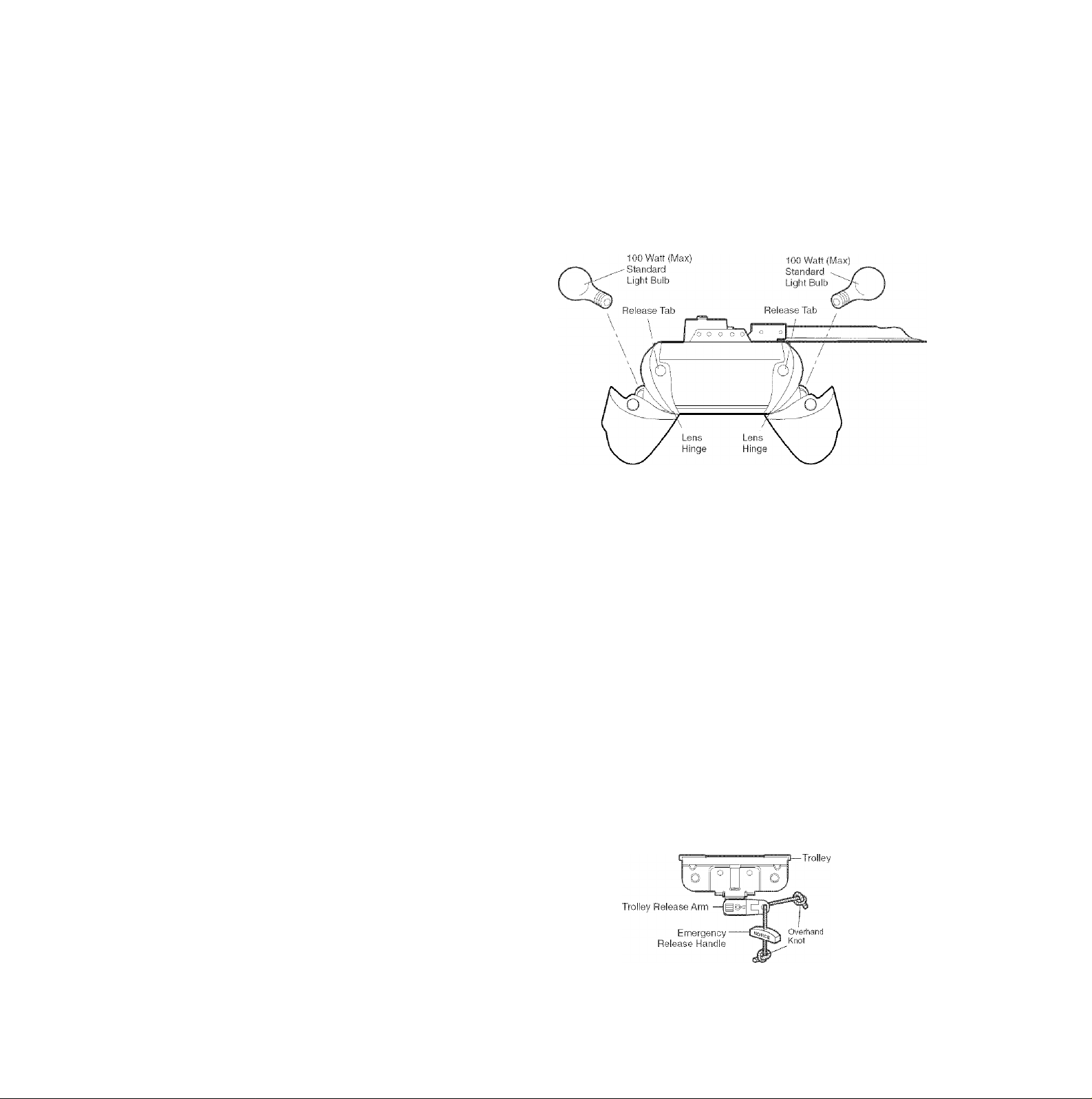
INSTALLATION STEP 10
Install the Lights
• Press the release tabs on both sides of lens. Gently
rotate lens back and downward until the lens hinge is
in the fully open position. Do not remove the lens.
• Install a 100 watt maximum light bulb in each socket.
Light bulb size should be A19, standard neck only. The
lights will turn ON and remain lit for approximately
4-1/2 minutes when power is connected. Then the
lights will turn OFF.
• Reverse the procedure to close the lens.
• Use A19, standard neck garage door opener bulbs for
replacement.
NOTE: Use only standard light bulbs. The use of short
neck or speciality light bulbs may overheat the endpanel
or light socket
CAUTION
To prevent possible OVERHEATING of the endpanel or light
socket:
• DO NOT use short neck or specialty light bulbs.
• DO NOT use halogen bulbs. Use ONLY incandescent.
To prevent damage to the opener:
• DO NOT use bulbs larger than 100W.
• ONLY use A19 size bulbs.
INSTALLATION STEP 11
Attach the Emergency Release Rope
and Handle
• Thread one end of the rope through the hole in the top
of the red handle so “NOTICE” reads right side up as
shown. Secure with an overhand knot at least
1" (2.5 cm) from the end of the rope to prevent
slipping.
• Thread the other end of the rope through the hole in
the release arm of the outer trolley.
• Adjust rope length so the handle is 6 feet (1.83 m)
above the floor. Ensure that the rope and handle clear
the tops of all vehicles to avoid entanglement. Secure
with an overhand knot.
NOTE: If it is necessary to cut the rope, heat seal the cut
end with a match or lighter to prevent unraveling.
A WARNING
To prevent possible SERIOUS INJURY or DEATH from a
falling garage door:
• If possible, use emergency release handle to disengage
trolley ONLY when garage door is CLOSED. Weak or broken
springs or unbalanced door could result in an open door
falling rapidly and/or unexpectedly.
• NEVER use emergency release handle unless garage
doorway is clear of persons and obstructions.
• NEVER use handle to pull door open or closed. If rope knot
becomes untied, you could fall.
22
Page 23
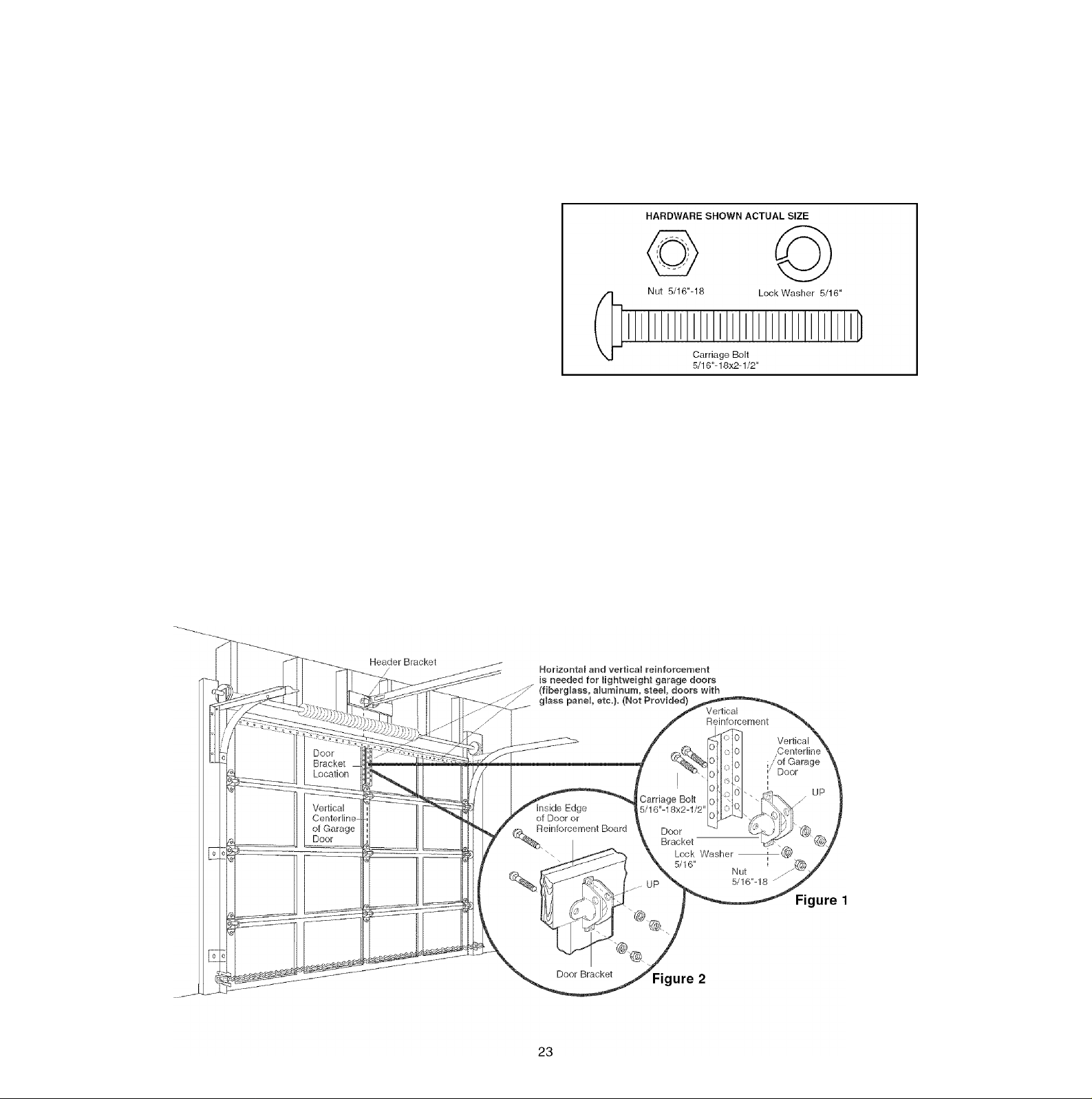
INSTALLATION STEP 12
Fasten the Door Bracket
Follow instructions which apply to your door type
as illustrated below or on the following page.
A horizontal reinforcement brace should be long
enough to be secured to two vertical supports. A
vertical reinforcement brace should cover the height
of the top panel.
The illustration shows one piece of angle iron as the
horizontal brace. For the vertical brace, two pieces of
angle iron are used to create a U-shaped support
(Figure 1). The best solution is to check with your garage
door manufacturer for an opener installation door
reinforcement kit.
NOTE: Many vertical brace installations provide for direct
attachment of the clevis pin and door arm. In this case
you will not need the door bracket; proceed to Installation
Step 12.
SECTIONAL DOORS
• Center the door bracket on the previously marked
vertical centerline used for the header bracket
installation. Note correct UP placement, as stamped
inside the bracket (Figure 2).
• Position the bracket on the face of the door within the
following limits:
A) The top edge of the bracket 2"-4" (5-10 cm) below
the top edge of the door.
B) The top edge of the bracket directly below any
structural support across the top of the door.
CAUTION
Fiberglass, aluminum or lightweight steel garage doors WILL
REQUIRE reinforcement BEFORE installation of door bracket.
Contact your door manufacturer for reinforcement kit.
• Mark and drill 5/16" left and right fastening holes.
Secure the bracket as shown in Figure 1 if there is
vertical reinforcement.
If your installation doesn't require vertical reinforcement
but does need top and bottom fastening holes for the
door bracket, fasten as shown in Figure 2.
Page 24

ONE-PIECE DOORS
Please read and comply with the warnings and
reinforcement instructions on the previous page. They
apply to one-piece doors also.
• Center the door bracket on the top of the door, in line
with the header bracket as shown. Mark either the left
and right, or the top and bottom holes.
• Drill 5/16" pilot holes and fasten the bracket with
hardware supplied.
If the door has no exposed framing, drill 3/16" pilot holes
and fasten the bracket with 5/16"x1-1/2" lag screws
(not provided) to the top of the door.
NOTE: The door bracket may be installed on the top
edge of the door if required for your installation. (Refer to
the dotted line optional placement drawing.) Drill 3/16"
pilot holes and substitute 5/16"x1-1/2" lag screws (not
provided) to fasten the bracket to the door.
24
Page 25

INSTALLATION STEP 13
Connect Door Arm to Trolley
Follow Instructions which apply to your door type as
illustrated below and on the following page.
SECTIONAL DOORS ONLY
• Make sure garage door is fully closed. Pull the
emergency release handle to disconnect the outer
trolley from the inner trolley. Slide the outer trolley back
(away from the door) about 2" (5 cm) as shown in
Figures 1,2 and 3.
• Figure 1:
- Fasten straight door arm section to outer trolley with
the 5/16"x1" clevis pin. Secure the connection with a
ring fastener.
- Fasten curved section to the door bracket in the
same way, using the 5/16"x1-1/4" clevis pin.
• Figure 2:
- Bring arm sections together. Find two pairs of holes
that line up and join sections. Select holes as far
apart as possible to increase door arm rigidity.
• Figure 3, Hole alignment alternative:
- If holes in curved arm are above holes in straight
arm, disconnect straight arm. Cut about 6"
(15 cm) from the solid end. Reconnect to trolley with
cut end down as shown.
- Bring arm sections together.
- Find two pairs of holes that line up and join with
bolts, lock washers and nuts.
• Pull the emergency release handle toward the opener
at a 45° angle so that the trolley release arm is
horizontal. Proceed to Adjustment Step 1, page 27.
Trolley will re-engage automatically when opener is
operated.
25
Figure 2
Figure 3
Page 26

ALL ONE-PIECE DOORS
1. Assemble the door arm, Figure 4:
• Fasten the straight and curved door arm sections
together to the longest possible length (with a 2 or 3
hole overlap).
• With the door closed, connect the straight door arm
section to the door bracket with the
5/16"x1-1/4" clevis pin.
• Secure with a ring fastener.
2. Adjustment procedures, Figure 5:
• On one-piece doors, before connecting the door arm
to the trolley, the travel limits must be adjusted. Limit
adjustment screws are located on the left side panel
as shown on page 27. Follow adjustment procedures
below.
• Open door adjustment: decrease UP travel limit
- Turn the UP limit adjustment screw
counter-clockwise 4 turns.
- Press the Door Control push button. The trolley will
travel to the fully open position.
- Manually raise the door to the open position (parallel
to the floor), and lift the door arm to the trolley. The
arm should touch the trolley just in back of the door
arm connector hole. Refer to the fully open
trolley/door arm positions in the illustration. If the
arm does not extend far enough, adjust the limit
further. One full turn equals 2" (5 cm) of trolley
travel.
• Closed door adjustment: decrease DOWN travel
limit
- Turn the DOWN limit adjustment screw clockwise
4 complete turns.
Door
- Press the Door Control push button. The trolley will
travel to the fully closed position.
- Manually close the door and lift the door arm to the
trolley. The arm should touch the trolley just ahead of
the door arm connector hole. Refer to the fully
closed trolley/door arm positions in the illustration. If
the arm is behind the connector hole, adjust the limit
further. One full turn equals 2" (5 cm) of trolley travel.
3. Connect the door arm to the trolley:
• Close the door and join the curved arm to the
connector hole in the trolley with the remaining clevis
pin. It may be necessary to lift the door slightly to
make the connection.
• Secure with a ring fastener.
• Run the opener through a complete travel cycle. If the
door has a slight “backward” slant in full open position
as shown in the illustration, decrease the UP limit until
the door is parallel to the floor.
NOTE: When setting the up limit on the following page,
the door should not have a “backward” slant when fully
open as Illustrated below. A slight backward slant will
cause unnecessary bucking and/or jerking operation as
the door is being opened or closed from the fully open
position.
Page 27

ADJUSTMENT STEP 1
Adjust the Travet Limits
Limit adjustment settings regulate the points at which the
door will stop when moving up or down.
To operate the opener, press the Door Control push bar.
Run the opener through a complete travel cycle.
• Does the door open and close completely?
• Does the door stay closed and not reverse
unintentionally when fully closed?
If your door passes both of these tests, no limit
adjustments are necessary unless the reversing test fails
(Adjustment Step 3, page 29).
Adjustment procedures are outlined below. Read the
procedures carefully before proceeding to Adjustment
Step 2. Use a screwdriver to make limit adjustments.
Run the opener through a complete travel cycle after
each adjustment.
NOTE: Repeated operation of the opener during
adjustment procedures may cause the motor to overheat
and shut off. Simply wait 15 minutes and try again.
NOTE: If anything interferes with the door’s upward
travel, it will stop. If anything interferes with the door’s
downward travel (including binding or unbalanced doors),
it will reverse.
A WARNING
Without a properly installed safety reversal system, persons
(particularly small children) could be SERIOUSLY INJURED
or KILLED by a closing garage door.
• Incorrect adjustment of garage door travel limits will
interfere with proper operation of safety reversal system.
• If one control (force or travel limits) is adjusted, the other
control may also need adjustment.
• After ANY adjustments are made, the safety reversal
system MUST be tested. Door MUST reverse on contact
with 1-1/2" high (3.8 cm) object (or 2x4 laid flat) on floor.
CAUTION
To prevent damage to vehicles, be sure fully open door
provides adequate clearance.
HOW AND WHEN TO ADJUST THE LIMITS
• If the door does not open completely but opens at
least 5 feet (1.5 m):
Increase up travel. Turn the UP limit adjustment screw
clockwise. One turn equals 2" (5 cm) of travel.
• If door does not open at least 5 feet (1.5 m):
Adjust the UP (open) force as explained in Adjustment
Step 2.
• If the door does not close completely:
Increase down travel. Turn the down limit adjustment
screw counterclockwise. One turn equals 2" (5 cm) of
travel.
If door still won't close completely try lengthening the
door arm (page 25) and decreasing the down limit.
• If the opener reverses in fully closed position:
Decrease down travel. Turn the down limit adjustment
screw clockwise. One turn equals 2" (5 cm) of travel.
• If the door reverses when closing and there is no
visible interference to travel cycle:
If the opener lights are flashing, the Safety Reversing
Sensors are either not installed, misaligned, or
obstructed. See Troubleshooting, page 21.
ADJUSTMENT LABEL
Test the door for binding; Pull the emergency release
handle. Manually open and close the door. If the door
is binding or unbalanced, call for a trained door
systems technician. If the door is balanced and not
binding, adjust the DOWN (close) force. See
Adjustment Step 2.
27
Page 28

ADJUSTMENT STEP 2
Adjust the Force
Force adjustment controls are located on the back panel
of the motor unit. Force adjustment settings regulate the
amount of power reguired to open and close the door.
If the forces are set too light, door travel may be
interrupted by nuisance reversals in the down direction
and stops in the up direction. Weather conditions can
affect the door movement, so occasional adjustment may
be needed.
The maximum force adjustment range is about 3/4 of
a complete turn. Do not force controls beyond that
point. Turn force adjustment controls with a screwdriver.
NOTE: If anything interferes with the door’s upward
travel, it will stop. If anything interferes with the door’s
downward travel (including binding or unbalanced doors),
it will reverse.
HOW AND WHEN TO ADJUST THE FORCES
1. Test the DOWN (close) force
• Grasp the door bottom when the door is about
halfway through DOWN (close) travel. The door
should reverse. Reversal halfway through down travel
does not guarantee reversal on a 1-1/2" (3.8 cm)
obstruction. See Adjustment Step 3, page 29. If the
door is hard to hold or doesn’t reverse,
DECREASE the DOWN (close) force by turning
the control counterclockwise. Make small adjustments
until the door reverses normally. After each
adjustment, run the opener through a complete cycle.
• If the door reverses during the down (close) cycle
and the opener lights aren’t flashing, INCREASE
DOWN (close) force by turning the control clockwise.
Make small adjustments until the door completes a
close cycle. After each adjustment, run the opener
through a complete travel cycle.
force beyond the minimum amount required to close
the door.
2. Test the UP (open) force
• Grasp the door bottom when the door is about
halfway through UP (open) travel. The door should
If the door is hard to hold or doesn’t stop,
stop.
DECREASE UP (open) force by turning the control
counterclockwise. Make small adjustments until the
door stops easily and opens fully. After each
adjustment, run the opener through a complete travel
cycle.
• If the door doesn’t open at least 5 feet (1.5 m),
INCREASE UP (open) force by turning the control
clockwise. Make small adjustments until door opens
completely. Re-adjust the UP limit if necessary. After
each adjustment, run the opener through a complete
travel cycle.
Do not increase the
A WARNING
Without a properly installed safety reversal system, persons
(particularly small children) could be SERIOUSLY INJURED
or KILLED by a closing garage door.
• Too much force on garage door will interfere with proper
operation of safety reversal system.
• NEVER increase force beyond minimum amount required to
close garage door.
• NEVER use force adjustments to compensate for a binding
or sticking garage door.
• If one control (force or travel limits) is adjusted, the other
control may also need adjustment.
• After ANY adjustments are made, the safety reversal
system MUST be tested. Door MUST reverse on contact
with 1-1/2" high (3.8 cm) object (or 2x4 laid flat) on floor.
Force Adjustment
Controls
Back Panel
ADJUSTMENT LABEL
smI--
Open Force
Close Force
28
Page 29

ADJUSTMENT STEP 3
Test the Safety Reversal System
TEST
• With the door fully open, place a 1 -1/2" (3.8 cm) board
(or a 2x4 laid flat) on the floor, centered under the
garage door.
• Operate the door in the down direction. The door must
reverse on striking the obstruction.
ADJUST
• If the door stops on the obstruction, it is not traveling
far enough in the down direction. Increase the DOWN
limit by turning the DOWN limit adjustment screw
counterclockwise 1/4 turn.
NOTE: On a sectional door, make sure limit
adjustments do not force the door arm beyond a
straight up and down position. See the illustration on
page 25.
• Repeat the test.
• When the door reverses on the 1 -1/2" (3.8 cm) board,
remove the obstruction and run the opener through 3
or 4 complete travel cycles to test adjustment.
• If the unit continues to fail the Safety Reverse Test, call
for a trained door systems technician.
A WARNING
Without a properly installed safety reversal system, persons
(particularly small children) could be SERIOUSLY INJURED
or KILLED by a closing garage door.
• Safety reversal system MUST be tested every month.
• If one control (force or travel limits) is adjusted, the other
control may also need adjustment.
• After ANY adjustments are made, the safety reversal
system MUST be tested. Door MUST reverse on contact
with 1-1/2" high (3.8 cm) object (or 2x4 laid flat) on the
floor.
IMPORTANT SAFETY CHECK:
Test the Safety Reverse System after;
• Each adjustment of door arm length, limits, or force
controls.
• Any repair to or adjustment of the garage door
(including springs and hardware).
• Any repair to or buckling of fhe garage floor.
• Any repair fo or adjusfment of the opener.
ADJUSTMENT STEP 4
Test The Protector Systeirf
• Press the remote control push button to open the door.
• Place the opener carton in the path of the door.
• Press the remote control push button to close the door.
The door will not move more than an inch (2.5 cm),
and the opener lights will flash.
The garage door opener will not close from a remote if
the indicator light in either sensor is off (alerting you to
the fact that the sensor is misaligned or obstructed).
If the opener closes the door when the safety
reversing sensor is obstructed (and the sensors are
no more than 6" (15 cm) above the floor), call for a
trained door systems technician.
29
Page 30

OPERATION
IMPORTANT SAFETY INSTRUCTIONS
A A WARNING
To reduce the risk of SEVERE INJURY or DEATH:
1. READ AND FOLLOW ALL WARNINGS AND INSTRUCTIONS.
2. ALWAYS keep remote controls out of reach of children.
NEVER permit children to operate or play with garage door
control push buttons or remote controls.
3. ONLY activate garage door when it can be seen clearly, it is
properly adjusted, and there are no obstructions to door
travel.
4. ALWAYS keep garage door in sight until completely closed.
NO ONE SHOULD CROSS THE PATH OE THE MOVING
DOOR.
5. NO ONE SHOULD GO UNDER A STOPPED, PARTIALLY
OPENED DOOR.
6. If possible, use emergency release handle to disengage
trolley ONLY when garage door is CLOSED. Weak or broken
springs or unbalanced door could result in an open door
falling rapidly and/or unexpectedly.
7. NEVER use emergency release handle unless garage
doorway is clear of persons and obstructions.
8. NEVER use handle to pull garage door open or closed. If
rope knot becomes untied, you could fall.
10. After ANY adjustments are made, the safety reversal
11. Safety reversal system MUST be tested every month.
12. ALWAYS KEEP GARAGE DOOR PROPERLY BALANCED
13. ALL repairs to cables, spring assemblies and other
14. ALWAYS disconnect electric power to garage door opener
15 SAVE THESE INSTRUCTIONS.
Using Your Garage Door Opener
Your Security+® opener and hand-held remote control
have been factory-set to a matching code which changes
with each use, randomly accessing over 100 billion new
codes. Your opener will operate with up to eight
Security+® remote controls and one Security+® Keyless
Entry System. If you purchase a new remote, or if you
wish to deactivate any remote, follow the instructions in
Programming section.
the
Activate your opener with any of the foliowing:
• The hand-held Remote Control: Hold the large push
button down until the door starts to move.
• The wall-mounted Door Control: Hold the push button
or bar down until the door starts to move.
• The Keyless Entry (See Accessories): If provided with
your garage door opener, it must be programmed
before use. See Programming.
When the opener is activated (with the safety
reversing sensor correctly installed and aligned)
1. If open, the door will close. If closed, it will open.
2. If closing, the door will reverse.
3. If opening, the door will stop.
4. If the door has been stopped in a partially open
position, it will close.
5. If obstructed while closing, the door will reverse. If the
obstruction interrupts the sensor beam, the opener
lights will blink for five seconds.
9. If one control (force or travel limits) is adjusted, the other
control may also need adjustment.
system MUST be tested.
Garage door MUST reverse on contact with 1-1/2" high
(3.8 cm) object (or a 2x4 laid flat) on the floor.
(see page 3). An improperly balanced door may not
reverse when required and could result in SEVERE INJURY
or DEATH.
hardware, all of which are under EXTREME tension, MUST
be made by a trained door systems technician.
BEFORE making ANY repairs or removing covers.
6. If obstructed while opening, the door will stop.
7. If fully open, the door will not close when the beam is
broken. The sensor has no effect in the opening cycle.
If the sensor is not installed, or is misaligned, the door
won't close from a hand-held remote. However, you can
close the door with the Door Control, the Outdoor Key
Switch, or Keyless Entry, if you activate them until down
travel is complete. If you release them too soon, the door
will reverse.
The opener lights will turn on under the following
conditions: when the opener is initially plugged in; when
power is restored after interruption; when the opener is
activated.
They will turn off automatically after 4-1/2 minutes or
provide constant light when the Light feature on the
Premium Control Console Panel is activated. Bulb size is
A19. Bulb power is 100 watts maximum.
Security4^ light feature: Lights will also turn on when
someone walks through the open garage door. With a
Premium Control Console, this feature may be turned off
as follows: With the opener lights off, press and hold the
light button for 10 seconds, until the light goes on, then
off again. To restore this feature, start with the opener
lights on, then press and hold the light button for 10
seconds until the light goes off, then on again.
30
Page 31

Using the Wall-Mounted Door Control
To Open the Door Manually
THE PREMIUM CONTROL CONSOLE
Lighted
Push Button
Press the lighted push button to open
or close the door. Press again to
reverse the door during the closing
cycle or to stop the door while it's
opening.
Light feature
Press the Light button to turn the opener light on or off. It
will not control the opener lights when the door is in
motion. If you turn it on and then activate the opener, the
light will remain on for 4-1/2 minutes. Press again to turn
it off sooner. The 4-1/2 minute interval can be changed to
1-1/2, 2-1/2, or 3-1/2 minutes as follows: Press and hold
the Lock button until the light blinks (about 10 seconds).
A single blink indicates that the timer is reset to 1-1/2
minutes. Repeat the procedure and the light will blink
twice, resetting the timer to 2-1/2 minutes. Repeat again
for a 3-1/2 minute interval, etc., up to a maximum of four
blinks and 4-1/2 minutes.
Lock feature
Designed to prevent operation of the door from hand-held
remote controls. However, the door will open and close
from the Door Control, the Outdoor Key Switch and the
Keyless Entry Accessories.
To activate, press and hold the Lock button for 2
seconds. The push button light will flash as long as the
Lock feature is on.
To turn off, press and hold the Lock button again for
2 seconds. The push button light will stop flashing. The
Lock feafure will also turn off whenever the “learn” button
on the motor unit panel is activated.
Additional feature when used with the 3-Function
hand-held remote
To control the opener lights:
In addition to operating the door, you
may program the remote to operate
the lights.
1. With the door closed, press and hold
a small remote button that you want
to control the light.
2. Press and hold the Light button on the door control.
3. While holding the Light button, press and hold the Lock
button on the door control.
4. After the opener lights flash, release all buttons.
¿k WARNING
To prevent possible SERIOUS INJURY or DEATH from a
falling garage door:
• If possible, use emergency release handle to disengage
trolley ONLY when garage door is CLOSED. Weak or
broken springs or unbalanced door could result in an open
door falling rapidly and/or unexpectedly.
• NEVER use emergency release handle unless garage
doorway is clear of persons and obstructions.
• NEVER use handle to pull door open or closed. If rope knot
becomes untied, you could fall.
DISCONNECT THE TROLLEY:
The door should be fully closed if possible. Pull down on
the emergency release
handle (so that the trolley
-Trolley
release arm snaps into a
vertical position) and lift the
door manually.
The lockout feature
prevents the trolley from
Trolley Release
Arm (in Manual
Disconnect Position)
reconnecting automatically,
and the door can be raised
and lowered manually as often
as necessary.
TO RE-CONNECT THE TROLLEY:
Pull the emergency release
handle toward the opener at
Lockout position
(Manual disconnect)
I—Trolley
Trolley
Release
Arm
an angle so that the trolley
release arm is horizontal. The
trolley will reconnect on the
next UP or DOWN operation,
To reconnect
either manually or by using the
door control or remote.
31
Page 32

CARE OF YOUR OPENER
THE REMOTE CONTROL BATTERY
LIMIT AND FORCE
ADJUSTMENTS:
FORCE CONTROLS
Weather conditions may cause
some minor changes in door
operation requiring some re
adjustments, particularly during
the first year of operation.
LIMIT CONTROLS
Pages 27 and 28 refer to the limit
and force adjustments. Only a
screwdriver is required. Follow the
.. .. .. .....
.....
"I
instructions carefully.
Repeat the safety reverse test
q>
(Adjustment Step 3, page 29)
after any adjustment of limits or force.
MAINTENANCE SCHEDULE
Once a Month
• Manually operate door. If it is unbalanced or binding,
call a trained door systems technician.
• Check to be sure door opens & closes fully. Adjust
limits and/or force if necessary (See pages 27 and 28).
• Repeat the safety reverse test. Make any necessary
adjustments (See Adjustment Step 3).
Once a Year
• Oil door rollers, bearings and hinges. The opener does
not require additional lubrication. Do not grease the
door tracks.
A WARNING
To prevent possible SERIOUS INJURY or DEATH:
• NEVER all ow small children near batteries.
• If battery is swallowed, immediately notify doctor.
The lithium battery should
produce power for up to
5 years. To replace battery,
use the visor clip or
screwdriver blade to pry open
the case as shown. Insert
battery positive side up (+).
Dispose of old battery properly.
NOTICE: To comply with FCC and or Indiisiry Canada rules (1C), adjustment or modifications of
this receiver and/or transmitter are prohibited, except for changing the code setting or replacing
the battery. THERE ARE NO OTHER USER SERVICEABLE PARTS.
Tested to Comply with FCC Standards FOR HOME OR OFFICE USE. Operation is subject to the
following two conditions: (1) this device may not cause harmful interference, and (2) this device
must accept any interference received, Including interference that may cause undesired operation.
Open this end
first to avoid
cracking
housing
32
Page 33

HAVING A PROBLEM?
1. My door will not close and the light bulbs blink on
my motor unit: The safety reversing sensor must be
connected and aligned correctly before the garage
door opener will move In the down direction.
• Verify the safety sensors are properly installed,
aligned and free of any obstructions. Refer to
Installation Step 4: Install The Protector Systerrf.
• Check diagnostic LED for flashes on the motor unit
then refer to the Diagnostic Chart on the following
page.
2. My remotes will not activate the door:
• Verify your Premium door control Is not blinking. If it
is blinking, deactivate the Lock Mode following the
instructions for Using the Premium Control Console.
• Reprogram remotes following the programming
instructions. Refer to Programming.
• If remote will still not activate your door, check
diagnostic LED for flashes on motor unit then refer to
Diagnostic Chart on the following page.
Sending Eye Safety Reversing
Sensor (Amber indicator Light)
Receiving Eye Safety Reversing
Sensor (Green indicator Light)
3. My door reverses for no apparent reason: Repeat
safety reverse test after adjustments to force or travel
limits. The need for occasional adjustment for the force
and limit settings is normal. Weather conditions in
particular can affect door travel.
• Manually check door for balance or any binding
problems.
• Refer to Adjustment Step 2, Adjust the Force.
4. My door reverses for no apparent reason after fully
closing and touching the floor: Repeat safety
reverse test after adjustments to force or travel limits.
The need for occasional adjustment for the force and
limit settings is normal. Weather conditions in particular
can affect door travel.
• Refer to Adjustment Step 1, Adjust the UP and
DOWN Travel Limits. Decrease down travel by
turning down limit adjustment screw clockwise.
5. My lights will not turn off when door is open:
• The garage door opener is equipped with a security
light feature. This feature activates the light on when
the safety sensor beam has been obstructed. Refer
to Operation section; Using the
Control, Light Feature.
Wall Mounted Door
33
Page 34

Diagnostic Chart
Safety reversing sensors
wire open (broken or
disconnected).
OR
Safety reversing sensors
wire shorted or
black/white wire
reversed.
Door control or
wire shorted.
issue. Consult Diagnostic Chart below.
Symptom: One or both of the Indicator lights on the safety sensors do
not glow steady.
• Inspect sensor wires for a short (staple in wire), correct wiring poiarity (biack/white
wires reversed), broken or disconnected wires, repiace/attach as needed.
• Disconnect ail wires from back of motor unit.
• Remove sensors from brackets and shorten sensor wires to 1 -2 ft (30-60 cm) from
back each of sensor.
• Reattach sending eye to motor unit using shortened wires. If sending eye indicator
light giows steadily, attach the receiving eye.
• Aiign sensors, if the indicator iights glow replace the wires for the sensors. If the
sensor indicator lights do not light, replace the safety sensors.
Symptom: LED is not lit on door control.
• Inspect door control/wires for a short (staple in wire), replace as needed.
• Disconnect wires at door control, touch wires together. If motor unit activates,
replace door control.
• If motor unit does not activate, disconnect door control wires from motor unit.
Momentarily short across red and white terminals with jumper wire. If motor unit
activates, replace door control wires.
Safety reversing sensors
slightly misaligned
(dim or flashing LED).
Motor overheated or
possible RPM sensor
failure. Unplug to reset.
Motor Circuit Failure.
Replace Receiver
Logic Board.
Symptom: Sending indicator light glows steadily, receiving indicator light is
dim or flashing.
• Realign receiving eye sensor, clean lens and secure brackets.
• Verify door track is firmly secured to wall and does not move.
Symptom: Motor has over heated; the motor unit does not operate;
RPM Sensor = Short travel 6-8" (15-20 cm).
• Unplug unit to reset. Try to operate motor unit, check diagnostic code.
• If it is still flashing 5 times and motor unit moves 6-8" (15-20 cm), replace RPM
sensor.
• If motor unit doesn’t operate, motor unit is overheated. Wait 30 minutes and retry. If
motor unit still will not operate replace logic board.
Symptom: Motor unit doesn’t operate.
• Replace logic board because motor rarely fails.
34
Page 35

PROGRAMMING
NOTICE: If this Security4^ garage door opener is operated with a non-rolling code transmitter, the technical measure in
the receiver of the garage door opener, which provides security against code-theft devices, will be circumvented. The
owner of the copyright in the garage door opener does not authorize the purchaser or supplier of the non-rolling code
transmitter to circumvent that technical measure.
Your garage door opener has already been programmed at the factory to operate with your hand-held remote control.
The door will open and close when you press the large push button.
Below are instructions for programming your opener to operate with additional Security+® remote controls.
To Add or Reprogram a Hand-held Remote Control
USING THE “LEARN” BUTTON USING THE PREMIUM CONTROL CONSOLE
1. Press and release the “learn” button on
the motor unit. The learn indicator light
will glow steadily for 30 seconds.
2. Within 30 seconds, press and hold the
button on the hand-held remote* that
you wish to operate your garage door.
3. Release the button when the motor unit
lights blink. It has learned the code. It
light bulbs are not installed, two clicks
will be heard.
To Erase All Codes From Motor Unit
Memory
To deactivate any unwanted remote, tirst erase all codes:
Press and hold the “learn” button on
motor unit until the learn indicator light
goes out (approximately 6 seconds). All
previous codes are now erased.
Reprogram each remote or keyless entry
you wish to use.
1. Press and hold the button on the
hand-held remote* that you wish to
operate your garage door.
2. While holding the remote button, press
and hold the LIGHT button on the
Premium Control Console.
3. Continue holding both buttons while
you press the push bar on the
Premium Control Console (all three
buttons are held).
4. Release buttons when the motor unit
lights blink. It has learned the code. If
light bulbs are not installed, two clicks
will be heard.
*3-Function Remotes
If provided with your garage door opener, the large button
is factory programmed to operate it. Additional buttons on
any Security+® 3-Function
remote or compact remote
can be programmed to
operate other Security+®
garage door openers.
X
X
35
Page 36

To Add, Reprogram or Change a Keyless Entry PIN
NOTE: Your new Keyless Entry must be programmed to operate your garage door opener.
USING THE “LEARN” BUTTON USING THE PREMIUM CONTROL CONSOLE
1. Press and release the “learn" button
on motor unit. The learn indicator iight
wiil glow steadily for 30 seconds.
2. Within 30 seconds, enter a four digit
personal identification number (PIN) of
your choice on the keypad. Then
press and hold the ENTER button.
3. Release the button when the motor
unit lights blink. It has learned the
code. If light bulbs are not installed,
two clicks will be heard.
To change an existing, known PIN
If fhe existing PIN is known, it may be changed by one
person without using a ladder.
1. Press the four buttons for fhe present PIN, then press
and hold the # button.
The opener light will blink twice. Release the # button.
2. Press the new 4-digit PIN you have chosen, then
press Enter.
The motor unit lights will blink once when the PIN has been
learned.
Test by pressing the new PIN, then press Enter. The door
should move.
To set a temporary PIN
You may authorize access by visitors or service people with
a temporary 4-digit PIN. After a programmed number of
hours or number of accesses, fhis temporary PIN expires
and will no longer open the door. It can be used to close the
door even after it has expired. To set a temporary PIN:
1. Press the four buttons for your personal entry PIN (not
the last temporary PIN), then press and hold the ^
button.
The opener light will blink three times. Release the
button.
NOTE: This method requires two people If the Keyless
Entry is already mounted outside the garage.
1. Enter a four digit personal identification
number (PIN) of your choice on the
keypad. Then press and hold ENTER.
, While holding the ENTER button, press
and hold the LIGHT button on the
Premium Control Console.
3. Continue holding the ENTER and
LIGHT buttons while you press the push
bar on the Premium Control Console (all
three buttons are held).
4. Release buttons when the motor unit
lights blink. It has learned the code. If
light bulbs are not installed, two clicks
will be heard.
2. Press the temporary 4-digit PIN you have chosen, then
press Enter.
The opener light will blink four times.
3. To set the number of hours this temporary PIN will work,
press the number of hours (up to 255), then press
OR
3. To set the number of times this temporary PIN will work,
press the number of times (up to 255), then press #.
The opener light will blink once when the temporary PIN
has been learned.
Test by pressing the four buttons for the temporary PIN,
then press Enter. The door should move. If the temporary
PIN was set to a certain number of openings, remember
that the test has used up one opening.To clear the
temporary password, repeat steps 1-3, setting the number
of hours or times to 0 in step 3.
One Button Close: Opener can be closed by pressing only the ENTER button if the one button close feature has been
activated. This feature has been activated at the factory. To activate or deactivate this feature press and hold buttons 1
and 9 for 10 seconds. The keypad will blink twice when the one button close is active. The keypad will blink four times
when one button close is deactivated.
36
Page 37

REPAIR PARTS
Rail Assembly Parts
Installation Parts
KEY
PART
NO.
NO. DESCRIPTION
1 81C275 Rack
2 41A6263 Hardware bag (includes
sprocket coupling)
3 12B890 Left rail bracket
4 12B900 Right rail bracket
5 41A6264 Screw drive rail assembly
Complete 7' (2.1 m)
6 12B889 Rail support brace
7 41A6262 Complete trolley assembly
8 41A4836 Drive sprocket kit
NOT SHOWN
28A143 Rail Clips
C<'"'
KEY
NO.
7
PART
NO. DESCRIPTION
1 41A4884 Premium control console
2 41A6140 3-Function remote control case
(no circuit board)
3 10A20 3V 2032 Lithium battery
4 29B137 Visor clip
5 41A2828 Emergency release rope & handle assy.
6 41B4494-1 2-Conductor bell wire: white & white/red
7 41A4353 Header bracket w/clevis pin &fastener
8 41A5047 Door bracket w/clevis pin & tastener
9 41A5034 Safety sensor kit: receiving and sending
eyes with 3' (.9 m)
2-conductor bell wire attached
10 178B34 Straight door arm section
11 12B776 Hanging bracket
12
178B35 Curved door arm section
13 41A5266-1 Satety sensor bracket
NOT SHOWN
41A4675-9 Installation hardware bag (see page 7)
114A3390 Owner’s manual
37
Page 38

Motor Unit Assembly Parts
ft ^6
KEY
NO.
1 31C568 Drive shaft cover 8 41A4837-1 Worm gear and retainer
2 41B4245 Line cord 9 41A6635 Low voltage wire harness
3 30B620 Capacitor - 1/2
4 41A3150 Terminal block w/screws
5 41 D4671 Limit switch assembly
6 41A6241 Motor drive assembly
6a 20B21-1 Drive belt
7 41C4672 Screw drive RPM kit
PART
NO. DESCRIPTION
KEY
NO.
9a 41A6634 High voltage wire harness
10 41AS050R-2 Receiver logic board assy.
11 41A5594-4 Cover
12 41C22-1 Drive coupling hub
13 175B88 Light socket
14 108D77 Light lens
PART
NO. DESCRIPTION
Brown Contact
Wire
Drive l>vf
Gear
(Down)
jmlj:
H :,Ki 1!
Center Limit (Up) vpltow
Contact Contact
LIMIT SWITCH ASSY.
'Grey
Wire
38
Page 39

ACCESSORIES
139.53702 Emergency Key Release:
Required for a garage with NO
access door. Enables homeowner to
open garage door manually from
outside by disengaging trolley.
139.53405
8 Foot Rail Extension:
To allow an 8 foot door to open fully.
139.53589
Support Brackets:
For finished ceilings or where
additional support is required, based
on garage construction. Includes
brackets and fastening hardware.
Door Clearance Brackets:
(For Sectional Doors Only)
Replaces top brackets and rollers on
door to reduce height of door travel.
For use when installing opener in
garage with low headroom clearance.
139.53753 SECURITY+® 3-Function Remote
Control:
Includes visor clip.
SECURITY+® Compact
3-Function Remote Control:
With loop for attaching key ring.
139.53754
SECURITY+® Keyless Entry:
Enables homeowner to operate garage
door opener from outside by entering a
password. Also can add a temporary
password for visitors or service persons.
139.53687
Premium Control Console:
Provides a lock feature to prevent
operation of garage door from portable
remotes. A light feature controls the
opener lights. Can be used to program
the opener to accept additional remotes.
41A5281
Extension Brackets:
(Available only through Sears Parts
& Service)
(Optional) For safety sensor
installation onto the wall or floor.
139.53749 Plug-In Light Control:
Enables homeowner to turn on a lamp,
television or other appliance from car,
bedside, or anywhere in the home with
a remote.
WARRANTY
igEfHlElfH]fi5fH]figfH]fi3fH]EifH]EifH]fi3fH]fi3fH]EifH]EifH]fi3fH]fi3fH]EifH]EifH]EifH]fi3fH]fi3fH]EifH]EifH]fi3fH]fi3fH]fi3fH]fi3fH]figfH]tigfH]ti3fH][i3fH][i3fH][i3fr9[i3fH][i3frgE^
CRAFTSMAN GARAGE DOOR OPENER LIMITED WARRANTY
For 90 days from the date of purchase, this product will be repaired, free of charge, if defective in material or workmanship.
From the 91st day up to 3 year from the date of purchase, replacement parts for any defective parts on this product will be furnished, free of charge. You pay for labor.
From the 91 st day and through 7 years, if the motor on this product is defective, a replacement motor will be furnished free of charge. You pay for labor.
This Craftsman Garage Door Opener Limited Warranty does not cover light bulbs or repair parts necessary because of operator abuse or negligence, including the failure to
install, adjust and operate this garage door opener according to instructions contained in the owner's manual. This limited warranty also does not cover any problems caused
Seller will not be liable for loss or damage to property or any incidental or consequential loss or expense from property damage due directly or indirectly to the use of
this product. Some states do not allow the exclusion or limitation of incidental or consequential damages, so the above limitation or exclusion may not apply to you.
Except for the motor, alt implied warranties for this product, including but not limited to any implied warranties of merchantability and fitness for a particular purpose,
are limited in duration to the 91st day through 3-year limited warranty period set forth above. All implied warranties with respect to the motor are limited in duration to
the 91st day through 7-year limited warranty period set forth above. No implied warranties will exist or apply after such periods. Some States do not allow limitations
FROM THE 91 ST DAY, WARRANTY SERVICE IS AVAILABLE BY SIMPLY CONTACTING THE NEAREST SEARS STORE OR SEARS SERVICE CENTER IN THE UNITED
This warranty gives you specific legal rights, and you may also have other rights which vary from state to state.
on how long an implied warranty lasts, so the above limitations may not apply to you.
WARRANTY SERVICE IS AVAILABLE BY CALLING 1-800-4-MY-HOME®.
This warranty applies only while this product is in use in the United States,
90-DAY IN-HOME FULL WARRANTY ON PRODUCT
ADDITIONAL LIMITED WARRANTY ON PARTS
ADDITIONAL LIFETIME LIMITED WARRANTY ON MOTOR
WARRANTY RESTRICTION
by interference.
LIMITATION ON LIABILITY
DISCLAIMER OF iMPLIED WARRANTIES
STATES.
Sears, Roebuck and Co., Dept. 817WA, Hoffman Estates, IL 60179
39
Page 40

CONTENIDO
Introducción 2-7
Revisión de los símbolos y términos de seguridad
Preparación de la puerta de su cochera.............................................................3
Herramientas necesarias......................................................................................3
Planificación .......................................................................................................4-5
Inventario de la caja de cartón ............................................................................6
Inventario de piezas..............................................................................................7
............................................
Montaje 8-11
Monte el riel ....................................................................................................... 8-9
Fije el riel a la unidad del motor y instale el trole ............................................10
Fijación de las ménsulas del riel ......................................................................11
Instalación 11-26
Instrucciones importantes para la instalación.................................................11
Determine dónde va a instalar la Ménsula del Cabezal
Instale la ménsula del cabezal...........................................................................13
Colocación del riel en la ménsula del cabezal.................................................14
Instale La Sistema de Protección®
Coloque el abridor en posición
Cuelgue el abridor ..............................................................................................19
Instale la unidad de control de la puerta
Requisitos para la instalación eléctrica............................................................21
Termine la instalación del sensor del sistema reversa
de seguridad........................................................................................................21
Instale las luces...................................................................................................22
Coloque la cuerda y la manija de emergencia
Fije la ménsula de la puerta
Conecte el brazo de la puerta al trole
.............................................................
..........................................................................
.........................................................
.........................................................................
........................................................
.................................
15-17
...............................................
23-24
25-26
18
20
22
12
OpBración 30-34
Instrucciones importantes de seguridad
2
Cómo usar su abridor de puerta de cochera
Cómo usar la unidad de control de la puerta ..................................................31
Cómo abrir la puerta manualmente..................................................................31
Mantenimiento de su abridor de puerta de cochera ......................................32
Si tiene algún problema......................................................................................33
Tabla de diagnóstico ..........................................................................................34
.........................................................
...................................................
Como Programar el Abridor 35-36
Como agregar o reprogramar un control remoto manual ... .35
Para borrar todos los códigos de la memoria de la
unidad del motor .......................................................................................
Controles remotos de 3 funciones...........................................................
Cómo agregar, reprogramar o cambiar un código
de entrada sin llave....................................................................
.............................
Accesorios
Garantía
Números de Servicio
Contratapa
30
30
.35
.35
36
37
37
Ajustes 27-29
Ajuste el límite del recorrido HACIA ARRIBA y
HACIA ABAJO .................................................................................................... 27
Ajuste la fuerza ...................................................................................................28
Pruebe el Sistema de Retroceso de Seguridad .............................................29
Pruebe la Sistema de Protección®...................................................................29
INTRODUCCIÓN
Revisión de ios Símbolos y Términos
de Seguridad
Este abridor de puerta de cochera ha sido diseñado y probado para un funcionamiento seguro, siempre y cuando se instale, se
pruebe, se opere y se le dé mantenimiento como se indica en este manual, cumpliendo al pie de la letra con todas las advertencias e
instrucciones generales aquí contenidas.
Estas advertencias y/o símbolos de seguridad que aparecen en
este manual le alertarán de que existe el riesgo de una lesión
Mecánica
IIÓ V ERTEfJC lÁ-'
Eléctrica
sería o de muerte si no se siguen las instrucciones
correspondientes. El peligro puede ser eléctrico (electrocución)
o mecánico. Lea las instrucciones con mucho cuidado.
Cuando vea esta palabra y/o símbolo de seguridad en este
manual, le alertará de que existe el riesgo de dañar la puerta
de la cochera y/o el abridor si no se siguen las instrucciones
correspondientes. Lea las instrucciones con mucho cuidado.
Page 41

PrBparación efe la puarta de su cochera
Antes de comenzar:
* Quite los seguros.
* Retire cualquier cuerda o cable que esté conectado
a la puerta.
* Haga la siguiente prueba con su puerta para verificar que
esté balanceada y que no se atore ni se pandee:
1. Levante la puerta hasta la mitad de su recorrido como se
muestra. Sueite la puerta. Si está balanceada, deberá
mantenerse en esa posición con sólo el soporte de los
resortes.
2. Suba y baje la puerta; observe si se afora con algo o si
se pandea.
Si su puerta se atora o se pandea, o no está balanceada
llame a un técnico especializado en sistemas de puertas.
Para evitar una LESIÓN GRAVE o INCLUSO LA MUERTE:
• SIEMPRE llame a un técnico profesional para que le dé servicio a
su puerta de cochera si ésta se atora, se pandea o está
desbalanceada. Una puerta de cochera que no esté bien
balanceada puede que no retroceda como se requiere.
• NUNCA intente aflojar, mover ni ajustar la puerta de su cochera,
los resortes de la puerta, los cables, las poleas, las ménsulas ni la
lomillería, pues todos estos elementos están bajo tensión
EXTREMA.
• Quite TODOS los seguros y retire TODAS las cuerdas conectadas
a la puerta de cochera ANTES de instalar y operar el abridor de la
puerta de cochera para evitar que se enreden.
Para evitar que se dañen el puerta y el abridor:
• SIEMPRE quite los seguros ANTES de instalar y/o de operar el
abridor.
• SOLAMENTE opere el abridor de puerta de cochera con corriente
de 120V, 60Hz con objeto de evitar su mal funcionamiento y que
el abridor se dañe.
Herramientas necesarias
Durante el montaje, instalación y ajuste del abridor, las
instrucciones le indicarán cómo usar las herramientas que
aparecen en la siguiente ilustración.
Page 42

Planificación
Identifique la altura y el tipo de su puerta de cochera. Revise el
área de su cochera y observe si alguna de las siguientes
instalaciones corresponden a la suya. Aveces se requieren
materiales adicionales, así que tal vez sea conveniente tener
esta hoja y las ilustraciones correspondientes a mano cuando
inicie la instalación de su abridor.
Dependiendo de sus necesidades individuales, es posible que
en algunos casos vaya a necesitar materiales o herramientas
que no se incluyen con este producto.
* Instalación Paso 1 - Observe la pared o el cielo raso justo
por encima de la puerta de la cochera. La ménsula del
cabezal debe estar firmemente sujeta a los soportes de la
estructura.
* Instalación Paso 4 - Dependiendo del tipo de construcción
de su cochera, es posible que necesite ménsulas de
extensión o bloques de madera para instalar los sensores.
* Instalación Paso 4 - El montaje en el piso del sensor que
activa el sistema de retroceso de seguridad podría requerir
piezas que no se incluyen.
* Instalación Paso 6 - Si el plafón o cielo raso de su cochera
tiene acabado, es posible que necesite una ménsula de
soporte y/o más pernos y tornillería para la instalación.
* ¿Hay otra puerta que dé acceso a la cochera? Si no es así,
será necesario contar con el sistema de llave de emergencia
Modelo 53702. Vea la página de Accesorios.
Observe el punto donde la puerta hace contacto con el piso.
El espacio entre la base de la puerta y el piso no debe
exceder 6 mm (1/4 de pulgada). Si no es así, se corre el
riesgo de que el sistema de retroceso de emergencia no
funcione correctamente. Vea Ajusfes, Paso 3. Será necesario
reparar ya sea el piso o la puerta.
INSTALACION CON UNA PUERTA SECCIONAL
• Si tiene una puerta de acero, aluminio, fibra de vidrio o con
paneles de vidrio, necesitará refuerzos verticales y
horizontales en la puerta. (Instalación, Paso 12.)
• El abridor se debe instalar por encima del centro de la
puerta, pero si existe algún resorte de tensión o placa de
apoyo en el paso de la ménsula del cabezal, se puede
instalar hasta a 1.22 m (4 pies) a la derecha o a la izquierda
del centro de la puerta. Vea Instalación, Pasos del 1 al 12.
• Si su puerta es de más de 2.13 m (7 pies) de altura, vea
Extensiones de riel en la sección de Accesorios.
Page 43

Planificación (continúa)
INSTALACIÓN CON PUERTAS DE UNA SOLA PIEZA
• Generalmente una puerta de una sola pieza no requiere
refuerzos adicionales. Si usted tiene una puerta de material
liviano y quiere reforzarla, consulte la Información respecto a
puertas seccionales, contenida en Instalación, Paso 12.
• Dependiendo del diseño de su puerta, tal vez necesite
piezas de montaje adicionales para la ménsula de la puerta
(Paso 12).
Sin un sistema de retroceso de seguridad que funcione
debidamente, al cerrar la puerta de la cochera se corre el riesgo de
que las personas (y en particular los niños pequeños) sufran
LESIONES GRAVES o INCLUSO LA MUERTE.
• El espacio entre la base de la puerta de la cochera y el piso N0
DEBE exceder 5 mm (1/4 de pulgada). De no ser así, el sistema
de retroceso de seguridad no va a funcionar debidamente.
• El piso o la puerta de la cochera SE DEBE reparar para eliminar
este espacio.
Page 44

Inventarío de las caja de cartón
Su abridor viene empacado en una caja de cartón que contiene
el motor y las piezas que se muestran en la siguiente
ilustración. Tome nota de que ios accesorios dependerán del
modelo que haya comprado. Si falta alguna pieza, revise con
cuidado el material de empaque ya que en ocasiones las
piezas se atoran en el mismo. DESTRUYA EL HULE ESPUMA
(vea la página 10). Toda la tornillería y las piezas necesarias
para el montaje e instalación de su puerta se ilustran en la
siguiente página. Conserve la caja y los materiales de
empaque hasta que la instalación y el ajuste se hayan
terminado.
Page 45

Inventario de Piezas
Antes de la instalación, organice todas las piezas en grupos como se muestra en la siguiente ilustración.
Page 46

MONTAJE PASO 1
Monte el riel
No encienda ni use ei abridor hasta que iiegue ai paso de
ia instaiación correspondiente, de otra manera corre ei
riesgo de complicar ei proceso de instalación.
1. Abra la caja de cartón del carril y saque el contenido
colocándolo sobre una superficie de trabajo horizontal.
Mantenga limpia y sin partículas mientras esté trabajando.
2. Identifique las secciones de carril y oriente las mismas sobre
una superficie plana según se muestra. El carril trasero tiene
un engranaje negro en un extremo. El carril delantero tiene
un soporte de plástico negro dentro del carril en el tornillo.
La sección restante es el carril central.
NOTA: Tonga cuidado al manipular la sección del carril central.
El tornillo puede deslizarse y salirse si la sección está
demasiado inclinada.
Quite el cartón de protección
II ■
Para evitar LASTIMARSE al armar ei riel, mantenga ias manos
alejadas de las uniones mientras se acoplan los tramos.
Page 47

Montaje el ríel (continúa)
3. Sujete los tirones de soporte del carril al carril trasero.
Introduzca sin apretar pernos hexagonales de 1/4-20x7/16"
en los agujeros alineados del carril de extremo y el tirante de
soporte del carril (Figura 1). No apriete con los dedos.
4. Extienda el tornillo de impulsión unos cuantos centímetros
desde el carril central, y deslice el manguito sobre el muñón
largo (Figura 2).
5. Enclave el muñón largo y corto del centro y los carriles
traseros. Deslice el manguito sobre la conexión del muñón
(Figura 3).
6. Coloque la presilla en C sobre el eje del muñón largo (carril
central) para asegurarse de que el manguito no se deslice
(Figura 4).
7. Deslice el carril central de modo que los agujeros del carril
central y del tirante del carril estén alineados (Figura 5). Fije
con pernos.
8. Apriete todos los pernos hexagonales.
9. Repita los pasos 3-8 para la sección de encabezado.
Figura 1
Figura 2
Tirante de soporte
del carril
Figura 4
Figura 5
Figura 3
Muñón corto
Muñón largo
Page 48

MONTAJE PASO 2
Fije el riel a la unidad del motor e instale
el trole
NOTA: Para facilitarle el montaje y ia instaiación de! motor,
vuelva a colocarlo dentro del hule espuma de protección, retire
la espuma después de concluir Instalación, Paso 4.
1. Sobre una superficie plana, alinee el riel ya armado al motor
como se muestra en la siguiente ilustración.
2. Deslice el copie sobre la polea del riel.
3. Deslice el riel a través de la ménsula del motor hasta que el
copie quede bien ajustado sobre la polea del motor.
4. Alinee los dos orificios para los pernos del riel con los
correspondientes orificios de la ménsula del motor. Fije con
los pernos hexagonales de 1/4-20x5/8 de pulg. y sus
respectivas tuercas. Apriételos con una llave de tuercas de
3/8 de pulg.
5. Deslice el trole dentro y a lo largo de la parte inferior del riel.
Alinee el trole con el bastidor y suba el brazo de liberación
para volver a enganchar el trole. El brazo de liberación del
trole debe estar horizontal (posición de bloqueo) con la
flecha apuntando hacia afuera desde la unidad del motor.
Ménsula
del motor
10
Page 49

MONTAJE PASO 3
Fijación de ias ménsuias dei riei
• Proceda a alinear las ménsulas en el extremo del riel, tal
como se muestra en la ilustración.
• Introduzca dos tornillos de cabeza hexagonal de 1/4-20x7/16
de pulg. y tuercas de seguridad. Ajuste firmemente con una
llave tubo de 3/8 de pulg.
Ha finalizado el ensamblado de su abre-puertas de garaje.
Lea las advertencias siguientes antes de proceder con la
sección de instalación.
Ménsula
INSTALACION
INSTRUCCIONES IMPORTANTES PARA LA INSTALACION
ADVERTENCIA
Para reducir el riesgo de una LESION GRAVE o
LA MUERTE:
1. LEA Y SIGA AL PIE DE LA LETRA TODAS LAS INSTRUCCIOMES
PARA LA INSTALACIÓN.
2. Instale el abridor de puerta de cochera SÓLO si la puerta de la
cochera está debidamente balanceada y lubricada. Si la puerta no
está debidamente balanceada es posible que np retroceda cuando
se requiera, lo que podría ocasionar una LESIÓN GRAVE o
INCLUSO LA MUERTE.
3. TODAS las reparaciones de los cables, resortes y otras piezas las
DEBE llevar a cabo un técnico especializado en sistemas de
puertas, ANTES de instalar el abridor.
4. Quite TODOS los seguros y retire TODAS las cuerdas conectadas a
la puerta de la cochera ANTES de instalar el abridor para de evitar
que se enreden.
5. Instale el abridor de la puerta de cochera a una distancia de 2.13
m (7 pies) del piso.
6. Monte la manija de liberación de emergencia a una distancia de
1.83 m (6 pies) del piso.
7. NUNCA conecte el abridor de la puerta de cochera a una fuente de
energía eléctrica hasta que así se indique.
8. NUNCA lleve puestos relojes, anillos ni ropa muy floja mientras
esté instalando o dando servicio al abridor, pues podrían atorarse
en la puerta de la cochera o en los mecanismos del abridor.
9. Instale el control de pared de la puerta de cochera:
• de manera que quede a la vista desde la puerta de la cochera.
• fuera del alcance de los niños y a una altura mínima de
5 pies (1.5 m).
• lejos de TODAS las partes móviles de la puerta.
10. Coloque la calcomanía que advierte sobre el riesgo de atraparse cerca
del control de la puerta de la cochera, en la pared.
11. Coloque la calcomanía que contiene la prueba de retroceso de
seguridad y liberación de emergencia a plena vista en la parte
interior de la puerta de la cochera.
12. Al concluir la instalación, pruebe el sistema de retroceso de
seguridad. La puerta DEBE retroceder al entrar en contacto con
un objeto de 3.8 cm (1-1/2 de pulg.) o bien con un pedazo de
madera de 5x10 cm (2x4 pulg.) puesto plano sobre el piso.
11
Page 50

INSTALACION PASO 1
Determine dónde va a instalar la Ménsula
del Cabezal
Para evitar una posible LESION GRAVE 0 INCLUSO LA MUERTE:
• La ménsula del cabezal DEBE quedar RÍGIDAMENTE sujeta al
soporte estructrual en la pared delantera o en el cielo raaso, de
no ser así es posible que la puerta del garaje no retroceda cuando
se requiera. N0 instale la ménsula del cabezal en muros falsos.
• Se DEBEN usar sujetadores para concreto si el montaje de la
ménsula del cabezal o del pedazo de madera de 3.8 cm
(2x4 pulg.) se hace en mampostería.
• NUNCA trate de aflojar, mover, ni ajustar la puerta del garaje, los
resortes, los cables, las pleas, las ménsulas ni la pernería, pues
todas estas piezas están bajo una tensión EXTREMA.
• SIEMPRE llame a un técnico especializado en sistemas de puertas
si la puerta del garaje se atasca, atora o si está desquilibrada. Una
puerta de garaje que no esté equilibrada puede no retroceder
cuando se requiera.
Los procedimientos de instalación varían según el tipo de
puerta de garaje. Siga las instrucciones que corresponden a su
tipo de puerta.
1. Con la puerta cerrada, localizar y marcar la línea vertical del
centro de la misma.
2. Extender la marca de la línea de centro hasta la pared sobre
la puerta.
Se puede fijar el soporte del cabezal dentro de una
distancia de 1.22 m (4 pies) a la izquierda o a la derecha
del centro de la puerta, solamente si estorba un resorte
de torsión o la placa central de soporte. También se
puede fijar al cielo raso (ver página 13) si el espacio
disponible fuera insuficiente. (Asimismo, se puede
instalar en forma invertida sobre la pared si fuese
necesario. Esto le otorgará aproximadamente 1 cm
(1/2 de pulg.) más de espacio).
Si necesita instalar la ménsula del cabezal en un tirante de
madera de 3.8 cm (2x4 pulg.) (ya sea en la pared o en el
cielo raso), fíje el tirante firmemente a soportes estructurales
usando tirafondos, tal como se indica aquí y en la página 13.
3. Abra la puerta hasta el punto más alto de su recorrido, tal
como se muestra. Marque una línea horizontal en la pared, a
las siguientes distancias sobre el punto más alto del
recorrido de la puerta:
• A 7.5 cm (3 pulg.) sobre el punto más alto de una puerta
seccional o puerta de una sola pieza con gulas.
• A20 cm (8 pulg.) sobre el punto más alto de una de una
sola pieza sin gulas.
A esta altura, el extremo superior de la puerta tendrá
suficiente espacio para su recorrido.
NOTA: Si la distancia total supera la altura disponible de el
garaje, use la altura máxima posible o consulte la página 13
para obtener información sobre la instalación en el cielo
raso.
Puerta de una pieza con riel guía horizontal
' Pared de cabecera
Pared de cabecera
¡- 20 cm (8 pulg.)
Puerta-
Puerta de una pieza sin riei guía:
accesorios de montaje
12
Articulación
Puerta de una pieza sin riel guía:
accesorios de articuíación
Page 51

INSTALACION PASO 2
Instale la ménsula del cabezal
La ménsula del cabezal se puede fijar a la pared sobre la
puerta del garaje o en el cielo raso. Siga las instrucciones que
sean más adecuadas para las necesidades de su instalación.
No instale la ménsula del cabezal en paneles huecos de
pared. Si va a fijar la ménsula del cabezal en mampostería,
hágalo con anclajes para concreto (no incluidos).
INSTALACIÓN DE LA MÉNSULA DEL CABEZAL EN LA
PARED
• Centre la ménsula en la linea vertical de centro, con el borde
inferior sobre la línea horizontal, tal como se indica en la
ilustración y con la flecha orientada hada el techo.
• Marque la ubicación de los agujeros verticales de la ménsula
(no utilice los agujeros destinados a montaje en cielo raso).
Haga los agujeros guía de 3/16 de pulg. y fije la ménsula
firmemente a un soporte estructural con los pernos incluidos.
Orificios para la instalación de pared
Orificios opcionales para
la instalación en la pared
Este orificio es solamente
para marcar !a posición de
iaménsula.Se debende
utilizar ios tornilíos tirafondo
para sujetar la ménsula.
INSTALACION DE LA MENSULA DEL CABEZAL EN EL
CIELO RASO
• Prolongue la línea vertical de centro hasta el cielo raso, tal
como se muestra.
• Centre la ménsula en la marca, a no más de 15 cm (6 pulg.)
de distancia de la pared. Asegúrese de que la flecha de la
ménsula apunte en dirección opuesta a la pared. La ménsula
se puede instalar a ras del cielo raso cuando el espacio
disponible es muy reducido.
• Marque los agujeros laterales. Haga los agujeros guía de
3/16 de pulg. y fije la ménsula firmemente a un soporte
estructural con los pernos incluidos.
Agujeros de montaje en techo
/\
Ì MOUt^
UP
Este orificio es solamen
para marcar la posición de
la ménsula. Se deben de
utilizar los tornillos tirafondo
para sujetar ia ménsula.
O
-Cielo raso terminado-
''■>1.0''
/" 'Y.
13
Page 52

INSTALACION PASO 3
Colocación del riel en la ménsula del
cabezal
• Coloque el abre-puertas sobre el piso, bajo la ménsula
instalada. Use el material del empaque como base para
protegerlo. NOTA: Si &l rosarte de ¡a puerta estuviera
interfiriendo, va a necesitar ayuda. Otra persona tendrá que
sostener el abre-puertas firmemente sobre un soporte
provisorio hasta que el riel pase el resorte.
• Coloque la ménsula del riel contra la ménsula del cabezal.
• Proceda a alinear los agujeros de las ménsulas y únalas con
una chaveta de 5/16x2-3/4 de pulg., tal se muestra. El
espaciador se puede instalar a ambos del carril.
Introduzca un anillo de seguro para terminar la unión.
Page 53

INSTALACION PASO 4
Instale la Sistema de Protección®
El sensor del sistema de retroceso de seguridad debe
estar instalado y alineado correctamente, antes de que el
abridor de la puerta de cochera mueva la puerta hacia
abajo.
INFORIVIACIÓN IMPORTANTE CON RESPECTO AL SENSOR
DEL SISTEMA DE RETROCESO DE SEGURIDAD
Si se instala y se alinea correctamente, el sensor del sistema
de retroceso de seguridad detectará cualquier obstáculo que
se cruce en el recorrido del rayo electrónico. El ojo emisor (el
que tiene la luz indicadora de color ámbar) envía un rayo
electrónico invisible al ojo receptor (el que tiene la luz
indicadora de color verde). Si algún objeto obstruyera este rayo
invisible mientras la puerta se está cerrando, la puerta se
detendrá automáticamente, retrocederá hasta abrirse por
completo, y la luz del abridor parpadeará diez veces.
Estos sensores se deben instalar en el interior de la cochera
de manera que el ojo emisor y el ojo receptor estén uno frente
al otro a ambos lados de la puerta y a una distancia máxima de
15 cm (6 pulg.) del piso. Ambos sensores se pueden instalar
en cualquiera de los dos lados de la puerta, ya sea el derecho
o el izquierdo, siempre y cuando nunca le dé el sol
directamente a la lente del ojo receptor.
mMmERmmm
Cerciórese de que la energía eléctrica no esté conectada al abridor
de la puerta de la cochera ANTES de instalar el sensor del sistema
de retroceso de seguridad.
Para evitar una LESIÓN GRAVE o INCLUSO LA MUERTE cuando la
puerta de la cochera se está cerrando:
• Conecte y alinee correctamente el sensor del sistema de retroceso
de seguridad. Este dispositivo de seguridad es necesario y N0 SE
DEBE desactivar.
• Instale el sensor del sistema de retroceso de seguridad de
manera que el rayo N0 ESTÉ a más de 15 cm (6 pulg.) del piso.
Las ménsulas para la instalación han sido diseñadas para que
se sujeten directamente al carril de la puerta, sin la necesidad
de tornillería ni piezas adicionales.
Si es necesario instalar las unidades sobre la pared, asegúrese
de que todas las ménsulas estén sujetas a una superficie
sólida, por ejemplo, uno de los soportes de la pared. Las
ménsulas de extensión están disponibles, si se necesitan (vea
la sección de accesorios). SI va a instalar los sensores sobre
ladrillo o mampostería, use un pedazo de madera para evitar
hacer orificios innecesarios sobre la mampostería en caso que
necesite cambiarlos de lugar.
El trayecto del rayo elecrónico invisible debe estar libre de
cualquier obstrucción. Ninguna de las partes de la puerta (los
carriles, resortes, bisagras, rodillos, u otras piezas o tornillería)
debe interrumpir el rayo cuando la puerta se esté cerrando.
Enfrentando la puerta desde el lado interno del garaje.
15
Page 54

INSTALACION DE LAS MENSULAS
Asegúrese de que el abridor no esté conectado a la
corriente eiéctrica.
Instale y alinee las ménsulas de manera que los sensores
estén uno frente al otro en los lados opuestos de la puerta, a
una distancia máxima de 15 cm (6 pulg.) del piso. Instale las
ménsulas de una de las tres maneras siguientes:
Instalación en el carril de la puerta de la cochera
(recomendada):
• Deslice ios brazos curvos sobre la orilla redondeada de cada
uno de los carriles de la puerta, con los brazos curvos
apuntando hacia la puerta. Colóquelos en su posición contra
el costado del carril. Debe quedar ras, con el reborde
pegado a la orilla posterior del carril, como se ilustra en la
Figura 1.
Si el carril de su puerta no soporta la ménsula firmemente, se
recomienda que la instale sobre la pared.
Instalación en la pared (Figura 2 y 3):
• Coloque la ménsula contra la pared con los brazos curvos
apuntando hacia la puerta. Cerciórese de que haya
suficiente espacio para que el rayo del sensor no esté
obstruido.
• Si es necesario tener más profundidad, puede usar
ménsulas de extensión (Vea Accesorios) o bloques de
madera.
• Use los orificios de montaje de la ménsula para marcar y
taladrar los (2) orificios de 3/16 de pulgada de diámetro a
cada lado de la puerta a una distancia máxima de 15 cm (6
pulg.) del piso.
• Fije la ménsula a la pared con tornillos de cabeza cuadrada
(no se incluyen).
• Si está usando ménsuias de extensión o bloques de madera
por la falta de espacio, asegúrese de que las dos unidades
queden a la misma distancia de la superficie de montaje.
Asimismo, asegúrese de que no haya ninguna obstrucción.
Instaiación en el piso (Figura 4):
• Use bloques de madera o ménsulas de extensión (Vea
Accesorios) para elevar las ménsulas de los sensores de
manera que las lentes queden a una distancia máxima de 15
cm (6 pulg.) del piso.
• Cuidadosamente mida e instale las unidades derecha y
Izquierda a la misma distancia con respecto a la pared.
Asegúrese de que no haya ninguna obstrucción.
• Fije al piso las ménsulas para los sensores con los
sujetadores para cemento, como se muestra en
la ilustración.
Figura 1 montaje de guía de puerta (lado derecho)
16
Figura 4
montaje en piso (LADO DERECHO)
pa'*® i
_ Fijar con tarugos
para concreto
(no incluidos)
Page 55

MONTAJE Y CABLEADO DE LOS SENSORES DEL
SISTEMA DE RETROCESO DE SEGURIDAD
* Deslice la cabeza de un perno de coche de 14-20x1/2 de
pulgada dentro de la ranura de los sensores. Use tuercas de
mariposa para sujetar los sensores a las ménsulas, con las
lentes de cada sensor frente a frente a ambos lados de la
puerta. Cerciórese de que la extensión de la ménsula no
obstruya las lentes (Figura 5).
• Apriete las tuercas de mariposa a mano.
Ruta recomendada para el cableado
1. Usando grapas con aislamiento, corra los cables de los dos
sensores hasta el riel del cabezal de la puerta (Figura 6).
2. Fije los cables en la parte superior de los rieles por medio de
las presillas de cables.
NOTA: Si su puerta de acceso está cerca de la puerta del
garaje, puede escoger instalar el control de la puerta en este
momento y fijar el cable de control de la puerta a lo largo del
riel con los cables del sensor.
Figura 5
Figura 6
17
Page 56

INSTALACION PASO 5
Coloque el Abridor en Posición
Siga las instrucciones correspondientes al tipo de puerta de su
garaje, como se muestra en la ilustración.
PUERTA SECCIONAL O PUERTA DE UNA SOLA PIEZA
CON RIEL DE GUÍA
Puede utilizar un tirante de madera de 3.8 cm (2x4 pulg.)
acostado para determinar la distancia ideal entre la puerta y el
riel.
• Quite el material de empaque.
• Levante el abre-puertas y colóquelo sobre una escalera. Si
la escalera no es lo suficientemente alta, va a necesitar
ayuda.
• Abra la puerta totalmente y apoye acostado un tirante de
madera de 3.8 cm (2x4 pulg.) sobre la parte superior de la
puerta, bajo el riel.
• Si la parte o el panel superior de la puerta toca el trole
cuando se la levanta, tire del brazo del seguro del trole para
separar la parte interna de la externa. Deslice el trole
externo hacia el motor. El trole puede permanecer
desconectado hasta el final del Paso 13.
Para evitar que la puerta del garaje sufra daños, apoye el riel del
abre-puertas sobre un tirante de madera de 3.8 cm (2x4 pulg.)
colocado sobre la parte superior de la puerta.
'1
ENGANCHADO
V
Brazo de
desenganche
del trole
PUERTA DE UNA SOLA PIEZA SIN RIEL
Puede utilizar un tirante de madera de 3.8 cm (2x4 pulg.) en
posición acostada para determinar la distancia ideal entre la
puerta y el riel.
• Quite el material de empaque.
• Levante el abre-puertas y colóquelo sobre una escalera. Si
la escalera no es lo suficientemente alta, va a necesitar
ayuda.
• Abra la puerta totalmente y apoye un tirante de madera de
3.8 cm (2x4 pulg.) parado sobre la parte superior de la
puerta, bajo el riel.
• La parte superior de la puerta debería quedar al mismo nivel
que el motor. No instale el abre-puertas a más de 10 cm
(4 pulg.) arriba de este punto.
18
Page 57

INSTALACION, PASO 5
Cuelgue el Abridor
Aquí se muestran tres ejemplos distintos para la instalación;
sin embargo, es posible que su cochera no concuerde con
ninguno de ellos. Las ménsulas de soporte deben estar en
ángulo (Figura 1), para que proporcionen un soporte rígido. En
caso de tener un cielo raso acabado (Figura 2 y Figura 3),
instale una ménsula de metal resistente en algún soporte de la
estrucura antes de instalar el abridor. No se incluye esta
ménsula ni la tornillería.
1. Mida la distancia desde cada lado de la unidad del motor
hasta el soporte de la estructura.
2. Corte las dos partes de las ménsulas colgantes a la medida
adecuada.
3. Taladre los orificios de 3/16 de pulgada en los soportes de la
estructura.
4. Fije un extremo de cada ménsula al soporte con tornillos de
cabeza cuadrada de 5/16 -18x1-7/8 pulg.
5. Fije el abridor a las ménsulas colgantes con pernos
hexagonales de 5/16 -18x7/8 pulg., y sus tuercas y
arandelas correspondientes.
6. Verifique que ei abridor esté centrado sobre la puerta (o
alineado con la ménsula del cabezal, si la ménsula no está
centrada sobre la puerta).
7. Quite el pedazo de madera de 5x10 cm (2x4 pulg.). Flaga
funcionar la puerta manualmente. Si la puerta golpea el riel,
suba la ménsula del cabezal.
NOTA: NO conecte el abridora la fuente de energía eléctrica
en este momento.
Para evitar la posibilidad de una LESIÓN GRAVE si se cayera
accidentalmente el abre-puertas, fíjelo EIRMEMENTE a soportes
estructurales del garaje. Se DEBEN usar sujetadores para concreto
si alguno de los soportes se va a instalar en manipostería.
19
Page 58

INSTALACION PASO 7
Instale la unidad de control de la puerta
Ubique el control de la puerta de manera que quede a la
vista desde la puerta y a una altura mínima de 1.5 m (5 pies)
donde los niños pequeños no lo puedan alcanzar y lejos de las
partes móviles de la puerta y de la tornillería. Si se va instalar en
un muro falso, taladre dos orificios de 5/32 de pulg. y use los
sujetadores que se incluyen. Para una instalación pre-cableada,
(por ejemplo, en una casa en construcción) los modelos de
consola se pueden instalar en una caja múltiple estándar
(Figura 2).
1. Pele 11 mm (7/16 de pulg.) del extremo del cable de campana y
conéctelo a las terminales de tornillo correspondientes al color del
cable en la parte posterior de la puerta de la unidad de control;
blanco a 2 y blanco y rojo a 1.
2. Con un desarmador abra la tapa por el costado. Sujete con un
tornillo autorroscante de 6AB por 1-1/4 de pulgadas (instalación
estándar) o con un tornillo para metales de 6 -32 por 1 pulgadas
(dentro de la caja múltiple) como se indica a continuación:
• Perfore e instaie el tornillo del fondo, permitiendo que 3 mm
(1/8 de pulg.) sobresalga sobre la superficie de la pared.
• Coloque la parte inferior de la unidad de control de la puerta
sobre la cabeza del tornillo y deslícelo para sujetarlo, apriete
el tornillo.
• Taladre y coloque el tornillo de la parte superior con
precaución de no romper la cubierta plástica de la unidad. No
apriete en exceso.
• Inserte las lengüetas superiores y cierre la cubierta.
3. (Instalación estándar solamente) Tienda el cable del timbre
hacia arriba en la pared y através del cieloraso a la unidad del
motor. Use grampas aisladas para asegurar el cable en varios
lugares. No perfore el cable con las grampas, lo que puede
crear un cortocircuito o circuito abierto. Si su puerta de acceso
está cerca de la puerta del garage, usted pued etender este
cable con con el cable del Sensor Inversor de Seguridad a lo
largo del tope del riel. Vea la página 17.
4. Pase todos los cables a través del orificio de la parte superior de
la unidad del motor por encima del bloque de terminales que se
encuentra en el panel posterior (Figura 3).
5. Pele 11 mm (7/16 de pulg.) de aislación de cada conjunto de
cables. Inserte el cable de control de la puerta dentro de los
conectores de conexión rápida por color: cable blanco a
blanco, cable blanco/rojo a rojo.
Separe los cables blancos y blanco/negro suficientemente para
conectar a los terminales de conexión rápida del abridor.Tuerza
juntos los cables del mismo color.Insertar los cables dentro de
los orificios de conexión rápida: blanco a blanco y blanco/negro
a gris.
NOTA: Al conectar controles múltiples de la puerta al abre-
puertas. tuerza juntos tos cables del mismo color. Inserte tos
cables en los orificios de conexión rápida: blanco a blanco y
rojo/blanco a rojo.
6. Use tachuelas o grapas para sujetar permanentemente la
calcomanía de advertencia sobre el riesgo de quedar atrapado;
esta calcomanía debe estar en la pared y cerca del control de
la puerta. La calcomanía de advertencia de la prueba de
reversa de seguridad y liberación manual debe colocarse en un
punto prominente del interior de la puerta de ia cochera.
NOTA: NO conecte el abridor a la energía eléctrica ni lo haga
funcionar en este momento. El trole hará el recorrido hasta llegar
a la posición completamente abierta, pero no regresará a la
posición cerrada hasta que el rayo del sensor esté conectado y
alineado debidamente.
Para evitar la posibilidad de una LESIÓN GRAVE o INCLUSO LA
MUERTE por electrocución:
• ANTES de instalar el control de la puerta, cerciórese de que la
energía eléctrica no esté conectada.
• Conecte el control SÓLO a cables de bajo voltaje de 24 VOLTIOS.
Para evitar la posibilidad de una LESIÓN GRAVE e INCLUSO
LA MUERTE cuando la puerta de la cochera se está cerrando;
• Instale el control de la puerta de manera que quede a la vista
desde la puerta de la cochera, fuera del alcance de los niños a una
altura mínima de 1.5 m (5 pies), y alejado de las partes móviles de
la puerta.
• NUNCA permita que los niños hagan funcionar o jueguen con los
botones de control de la puerta ni con los transmisores de control
remoto.
• Haga funcionar la puerta SÓLO si la puede ver claramente, si la
puerta está debidamente ajustada, y si no no hay ninguna
obstrucción en su recorrido.
• SIEMPRE tenga a la vista la puerta de la cochera hasta que esté
completamente cerrada. NUNCA permita que alguien se atraviese
en el recorrido de la puerta de la cochera cuando se está cerrando.
Conexiones para la Unidad de Control Exterior
Conecte a las terminales de conexión rápida: el blanco al
blanco; blanco/rojo al rojo.
ESTAS PIEZAS SE MUESTRAN EN SU TAMAÑO REAL
iïïïTiïïïïnTiïïïïlTm
8
Tornillo para ¡a consola de control de
6AB por 1-1/4 de pulg. (instalación estándar)
Tornillo para la consola de control de
6-32 por 1 pulg, {instalación precableada)
Figura 1
QUITAR Y VOLVER A
PONER LA TAPA
Para volver a
primero inse
las lengüetasuperiores .
Pele 11 mm (7/16 de pulg,) Insertar los cales a través de la abertura en el tope
de la unidad del motor sobre el bloque terminal, y a continuación dentro de los
terminales de conexión rápida.
Para soltar el cable, empuje la
Conexiones del
control de la puerta
Pele el cable 11 mm( 7/16 pulg.
20
lengüeta hacia dentro con la punta
de un destornillador
Figura 2 instalación precableada
Sujetadores para muro falso
Grapas con
aislamiento
Cable de campana de
24 voltios de dos conductores
Page 59

INSTALACION PASO 8
Requisitos para ia instaiación eiéctrica
Para evitar problemas con la instalación, no opere el abrepuertas de garaje ahora.
Para reducir el riesgo de electrocución, el abre-puertas de
garaje viene con enchufe con pata de conexión a tierra. Este
enchufe sólo se puede conectar a un tomacorriente con
conexión de puesta a tierra. Si el enhcufe no entra en el
tomacorriente de su instalación, contrate un electricista
profesional para que instale el tomacorriente adecuado.
Si la reglamentación municipal exige que su abre-puertas
tenga cableado permanente, siga los siguientes pasos.
Para efectuar una conexión permanente usando la entrada
superior de 7/8 de pulg. en la parte superior del motor:
• Quite los tornillos de la tapa del motor y desmonte la tapa.
• Quite el cordón de 3 patas.
• Conecte el cable negro de linea al tornillo del terminal de
bronce; el cable blanco (neutro) al tornillo del terminal
plateado, y el cable de tierra al tornillo verde. El abre-
puertas debe tener conexión a tierra.
• Vuelva a colocar la tapa.
Para evitar problemas con la instalación, no poner el abre-
puertas en funcionamiento antes del Paso 11.
Para evitar la posibilidad de una LESIÓN GRAVE 0 INCLUSO LA
MUERTE por electrocución o incendio:
• Asegúrese de que el abre-puertas no esté conectado a la energía
eléctrica y desconecte la alimentación eléctrica al circuito ANTES
de quitar la cubierta para establecer la conexión del cableado
permanente.
• Tanto la instalación como el cableado de la puerta de garaje
DEBEN cumplir con todos los códigos locales eléctricos y de
construcción,
• NUNCA use una extensión ni un adaptador de dos hilos, tampoco
modifique la clavija para poder enchufarla. Asegúrese de que el
abre-puertas esté puesto a tierra.
INSTALACION, PASO 9
Termine ia instaiación dei sensor dei
sistema de reversa de seguridad
CÓMO ALINEAR LOS SENSORES DE SEGURIDAD
• Conecte el abridor; las luces del sensor emisor y del sensor
receptarse deben de encender y permanecer encendidas si
todas las conexiones del cableado y la alineación se han
hecho correctamente.
La luz ámbar del sensor que emite el rayo se encenderá
aunque esté obstruido o fuera de alineación, pero si la luz
verde del sensor receptor del rayo está apagada, parpadea o
se ve baja, (y no hay ninguna obstrucción en el recorrido del
rayo de luz invisible) será necesario alinearlos.
•Afloje la tuerca de mariposa del sensor emisor y reajuste el
sensor. Apunte directamente al otro sensor y apriete la tuerca
de mariposa.
•Afloje la tuerca de mariposa del sensor receptor del rayo, y
reajuste hasta que reciba el rayo del sensor emisor. Una vez
que la luz verde brille permanentemente, apriete la tuerca de
mariposa.
DIAGNOSTICO DE FALLAS CON RESPECTO A LOS
SENSORES DEL SISTEMA DE REVERSA DE SEGURIDAD
1. Si la luz verde del sensor que emite el rayo no permanece
encendida después de la instalación, verifique lo siguiente:
• El suministro de corriente eléctrica al abridor.
• Que haya un corto circuito en alguno de los cables, ya sea
el banco, o el blanco y negro. Esto ocurre frecuentemente
donde hay alguna grapa.
•Algún error en la conexión de los cables de los sensores al
abridor.
• Algún cable roto.
2. Si la luz indicadora del sensor que emite el rayo enciende y
permanece encendida, pero la luz del otro sensor no
enciende:
• Verifique que estén correctamente alineados.
• Verifique que no haya un corto en el cable del sensor
receptor.
3. Si la luz indicadora del sensor receptor esta débil o baja,
verifique la alineación de los sensores.
NOTA: Si la trayectoria del rayo invisible se ve obstruida o está
fuera de alineación, al tratar de cerrar la puerta ésta se abrirá
automáticamente. Si la puerta está abierta, simplemente no se
podrá cerrar, y las luces de abridor parpadearán diez veces
(vea la página 15).
21
Page 60

INSTALACION PASO 10
Instale las Luces
• Oprima las lengüetas de liberación a ambos lados de la
lente. Rote la lente suavemente hacia atrás y hacia abajo
hasta que la bisagra quede en la posición totalmente
abierta. No quite la lente.
• Instale bombillos de 100 vatios como máximo en cada
porfalámpara. Los bombillos deben ser de Al 9 cuello
standard sólo. En cuanto se conecte la electricidad, las
luces se encenderán y permanecerán encendidas por
aproximadamente cuatro minutos y medio; luego las luces
se apagan.
• Invierta el procedimiento para cerrar la lente.
• Para reemplazo uso los bombillos para el abridor de puerta
de cochera de Al 9, estándar.
NOTA: Sólo utilíce bombillos estándar. El uso de bombillos de
cuello corto o especiales puede sobrecalentar el panel
o la porfalámpara.
Para evitar un posible SOBRECALENTAMIENTO del
portabombillas:
• N0 utilice bombillas de cuello corto ni de tipo especial.
• N0 utilice bombillas halógenas. Utilice SÓLO bombillas
incandescentes.
Para evitar daño al abridor:
• N0 utilice bombillas más grande que 100W.
• SÓLO utilice bombillas de tamaño Al 9.
Bombillo estándar
Bombillo estándar
INSTALACION PASO 11
Coloque la Cuerda y la Manija
de Emergencia
• Pase un extremo de la cuerda a través del orificio que se
encuentra en la parte superior de la manija roja de manera
que la palabra “NOTICE” (aviso) sea legible, como se indica
en la ilustración. Asegúrela con un
nudo por lo menos a 2.5 cm (1 pulg.) del extremo de la
cuerda para evitar que se resbale.
• Pase el otro extremo de la cuerda a través del orificio del
brazo de liberación del trole exterior.
• Ajuste el largo de la cuerda de tal manera que la manija
quede a 1.83 m (6 pies) del piso. Haga un nudo para
asegurarla. Para evitar que la cuerda o la manija se
enganche en algo, asegúrese de que no toquen el techo de
ningún vehículo.
NOTA: Si es necesario cortarla cuerda, queme con un cerillo
o un encendedor el extremo que cortó para sellarla y evitar que
se desenrede.
Para evitar la posibilidad de una LESION GRAVE 0 INCLUSO LA
MUERTE si la puerta del garaje se cae:
• De ser posible, use la manija de emergencia para soltar el trole
SÓLO cuando la puerta del garaje esté CERRADA. Si los resortes
están débiles o rotos, o bien si la puerta está desequilibrada, la
puerta podría caerse rápida y/o inesperadamente mientras se
encuentra abierta.
• NUNCA use la manija de emergencia a menos que la entrada del
garaje esté libre de obstrucciones y no haya ninguna persona
presente.
• NUNCA use la manija para abrir o cerrar la puerta. Si el nudo de la
cuerda se suelta, usted podría caerse.
22
Page 61

INSTALACION, PASO 12
Ff/e la ménsula de la puerta
Siga las instrucciones que correspondan al tipo de puerta de
cochera que usted tenga, como se muestra en la ilustración o
en la página siguiente.
Si usa un puntal horizontal, éste debe ser lo
suficientemente largo para sujetarlo a dos soportes
verticales. Si usa un puntal vertical, éste debe ser de la
altura del panel superior.
La ilustración muestra una pieza de hierro en ángulo como
puntal horizontal. Para el puntal vertical se deben usar dos
piezas de hierro en ángulo con objeto de crear un soporte en
“U” (Figura 1). La mejor solución es ponerse en contacto con la
compañía fabricante de la puerta de su cochera e informarse
acerca de los juegos de refuerzos de puertas para la
instalación de un abridor.
NOTA: Muchas de las instalaciones con soporte o
puntal vertical toman en cuenta la instalación directa de los
pasadores de chaveta y el brazo de la puerta. En este caso, no
necesitará instalar la ménsula para la puerta; proceda al
Paso 12.
PUERTAS SECCIONALES
• Coloque la ménsula para la puerta sobre la línea central
vertical que había marcado previamente para la instalación
de la ménsula del cabezal. Asegúrese de que la leyenda
“UP” (arriba) esté en la posición correcta, como está
indicado en la parte interior de la ménsula (Figura 2).
* Coloque la ménsula sobre la parte frontal de la puerta,
dentro de los límites siguientes:
A) El borde superior de la ménsula 5-10 cm (2-4 pulg.)
debajo del borde superior de la puerta.
B) La orilla superior de la ménsula debe estar directamente
debajo de algún soporte de la estructura a lo largo de la
parte superior de la puerta.
En el caso de puertas de fibra de vidrio, aluminio o acero ligero,
NECESARIO
colocar un refuerzo ANTES de instalar el marco de la
ES
puerta. Póngase en contacto con el fabricante de su puerta para
obtener un kit de refuerzo.
• Marque y taladre dos orificios de 5/16 pulg. para los
sujetadores a la derecha y a la izquierda. Sujete la ménsula
al refuerzo vertical (si éste existe), como se muestra en la
Figura 1.
Si el tipo de instalación de su cochera no requiere refuerzos
verticales, pero sí necesita los orificios para los sujetadores de
la ménsula, taladre y fíjelos como se muestra en la Figura 2.
Page 62

PUERTAS DE UNA SOLA PIEZA
Lea y respete todas las advertencias e instrucciones respecto a
los refuerzos, contenidas en la página anterior, Instalación de
puertas seccionales, ya que todos los refuerzos para su puerta
de una sola pieza son los mismos.
• Coloque la ménsula de la puerta en el centro de la parte
superior de la misma, alineada con la ménsula del cabezal,
según se indica en la ilustración. Marque ya sea los orificios
derecho e izquierdo o superior y inferior.
• Taladre los orificios piloto de 5/16 de pulg. y sujete la
ménsula con la tornilleria que se incluye.
Si la puerta no tiene un marco exterior expuesto, taladre dos
orificios de 3/16 de pulg. y sujete la ménsula a la parte superior
de la puerta con tornillos de cabeza cuadrada de 5/16x1-1/2 de
pulg. (no se incluyen).
NOTA: La ménsula para la puerta puede ser instalada sobre la
orilla superior de la puerta si es necesario para su instalación
en particular. (Vea la ilustración de colocación opcional,
señalada con la línea punteada). Taladre dos orificios de 3/16
de pulg. y sujete la ménsula a la parte superior de la puerta
con tornillos de cabeza cuadrada de 5/16x1-1/2 de pulgadas
(no se incluyen).
24
Page 63

INSTALACION PASO 13
Conecte e! brazo de la puerta al trole
Siga las instrucciones que correspondan al tipo de puerta de
cochera que usted tenga, como se muestra a continuación y en
la página siguiente.
SÓLO PARA PUERTAS SECCIONALES
• Cerciórese de que la puerta de la cochera esté
completamente cerrada. Tire de la manija de emergencia
para desconectar el trole exterior del trole interior. Deslice el
trole exterior hacia atrás (en dirección opuesta a la puerta)
por lo menos 5 cm (2 pulg.) como se indica en las Figuras 1,
2 y 3.
» Figura 1:
- Fije la sección recta del brazo de la puerta al trole exterior
usando un pasador de chaveta de 5/16x1 pulg. Asegure la
conexión con el anillo sujetador.
- Fije la sección curva del brazo a la ménsula de la puerta
de la misma manera, con un pasador de chaveta de 5/16
por 1-1/4 de pulg.
» Figura 2:
- Junte las dos secciones del brazo, localizando dos pares
de orificios que se puedan alinear. Seleccione dos orificios
que estén tan separados como sea posible para aumentar
la rigidez del brazo de la puerta.
• Figura 3, Opciones para aiinear ios orificios:
- En caso de que los orificios del brazo curvo no se puedan
alinear con los orificios del brazo recto, desconecte el
brazo recto y corte aproximadamente 15 cm (6 pulg.) del
extremo que no tiene orificios. Vuelva a conectarlo al trole,
con el extremo cortado hacia abajo, como se muestra.
- Junte las dos secciones de los brazos.
- Localice dos pares de orificios de ambas secciones que se
puedan alinear y únalos con tornillos, arandelas y tuercas.
• Tire de la manija de emergencia hacia el abridor en un
ángulo de 45 grados, de manera que el brazo de liberación
del trole esté en posición horizontal. Proceda a la sección de
Ajustes, Paso 1, en la página 27. El trole volverá a estar listo
automáticamente, cuando se opere el abridor.
25
Page 64

TODAS LAS PUERTAS DE UNA SOLA PIEZA
1. Arme el brazo de la puerta, Figura 4:
• Sujete las dos secciones de los brazos de la puerta (recto
y curvo) a la mayor distancia posible, de manera que dos o
tres de los orificios se sobrepongan uno al otro.
• Cierre la puerta y fije la sección recta del brazo a la
ménsula de la puerta con el pasador de chaveta de
5/f 6xf-1/4 de pulgada.
• Asegúrelos con un anillo sujetador.
2. Procedimiento de ajuste, Figura 5:
• Si tiene una puerta de una sola pieza, deberá ajustar los
límites del recorrido antes de conectar el brazo de la
puerta. Los tornillos de ajuste del límite de recorrido se
encuentran en el panel del lado izquierdo, como se
muestra en la ilustración que aparece en la página 27.
Siga el procedimiento de ajuste que aparece a
continuación.
> Ajuste de la puerta al abrirla: Disminuya el límite del
recorrido HACIA ARRIBA
- Ajuste el tornillo para ajustar el limite del recorrido HACIA
ARRIBA, dándole 4 vueltas hacia la izquierda.
- Oprima el botón de control de la puerta. El trole deberá ir
hasta la posición completamente abierta.
- Abra la puerta manualmente de manera que esté paralela
con el piso y suba el brazo de la puerta al trole. El brazo
de la puerta deberá tocar el trole justo en la parte
posterior del orificio conector. Consulte la ilustración
correspondiente al brazo de la puerta y al trole en su
posición completamente abierta. Si el brazo no se
extiende lo suficiente, ajuste el límite del recorrido de la
puerta; cada vuelta completa del tornillo equivale a 5 cm
(2 pulg.) del recorrido del trole.
• Ajuste de la puerta al cerrarla: Disminuya el límite del
recorrido HACIA ABAJO
- Ajuste el tornillo para ajustar el limite del recorrido HACIA
ABAJO, dándole 4 vueltas completas hacia la derecha.
Ménsula de la puerta
- Oprima el botón de control de la puerta, el trole deberá ir
hasta la posición completamente cerrada.
- Cierre la puerta manualmente y suba el brazo de la puerta
al trole. El brazo de la puerta deberá tocar el trole justo
delante del orificio conector del brazo de la puerta.
Consulte la ilustración correspondiente al brazo de la
puerta y al trole en su posición completamente cerrada. Si
el brazo queda detrás del orificio conector, ajuste el límite
del recorrido de la puerta; cada vuelta completa del tornillo
equivale a 5 cm (2 pulg.) de recorrido del trole.
3. Conecte el brazo de la puerta al trole:
• Cierre la puerta y sujete el brazo curvo al orificio conector
del trole con el último pasador de chaveta. Es posible que
necesite levantar un poco la puerta manualmente para
poder hacer esta conexión.
• Asegure con un anillo sujetador.
• Opere el abridor durante un ciclo completo del recorrido. Si
la puerta parece estar en cierto ángulo (hacia atrás)
cuando está completamente abierta, como se muestra en
la siguiente ilustración, disminuya el límite del recorrido
hacia arriba hasta que la puerta quede paralela al piso.
NOTA: Al establecer el límite hacia arriba como se indica en la
página siguiente, la puerta no debe tener una inclinación “hacia
atrás" cuando esté totalmente abierta, como se ilustra abajo.
Una ligera inclinación hacia atrás ocasionará que la puerta se
pandee innecesariamente y/o que la operación no sea uniforme
al abrir o cerrar la puerta desde la posición totalmente abierta.
Figura 5
Page 65

AJUSTES PASO 1
Ajuste el límite del recorrido
HACIA AfífílBA HACIA ABAdC
Al ajustar el límite del recorrido de la puerta, se regula hasta
qué punto ésta se detendrá al abrir y al cerrar.
Para poner en marcha el abridor, oprima el botón de control de
la puerta. Haga funcionar el abridor durante un ciclo completo
del recorrido.
• ¿La puerta se abre y se cierra completamente?
• ¿La puerta se mantiene cerrada y no retrocede
indebidamente cuando está completamente cerrada?
Si su puerta pasa estas dos pruebas, no necesitará hacer más
ajustes al límite del recorrido. Pero si no pasa la prueba de la
retroceso, tendrá que ajustar el límite del recorrido. (Vea
Ajustes, Paso 3, en la página 29.)
El procedimiento de ajuste se explica a continuación: Lea el
procedimiento con cuidado antes de continuar con el Paso 2
de la sección de Ajustes. Use un destornillador para hacer los
ajustes al límite del recorrido. Después de llevar a cabo un
ajuste, haga funcionar el abridor durante un ciclo completo
del recorrido,
NOTA: El abrir y cerrar la puerta varias veces durante el
procedimiento de ajuste puede causar que el abridor se
sobrecaliente y al sobrecalentarse se apagará. Sólo espere
quince minutos y continúe con los ajustes necesarios.
NOTA: Si algo interfiere con el recorrido de la puerta en su
trayectoria hacia arriba, ésta se detendrá. Pero si algo la
obstruye en su trayectoria hacia abajo (incluyendo un
posible desnivel o desbalanceo), la puerta retrocederá.
Si el sistema de auto-reversa de seguridad no se ha instalado
debidamente, las personas (y los niños pequeños en particular)
podrían sufrir LESIONES GRAVES 0 INCLUSO LA MUERTE cuando
se cierre la puerta del garaje.
• El ajuste incorrecto de los límites del recorrido de la puerta del
garaje habrá de Interferir con la operación adecuada del sistema
de auto-reversa de seguridad.
• Si se ajusta uro de los controles (límites de la fuerza o del
recorrido), es posible que sea necesario ajustar también el otro
control.
• Después de llevar a cabo cualquier ajuste, SE DEBE probar el
sistema de auto-reversa de segundad. La puerta DEBE retroceder
al entrar en contacto con un objeto de 3.8 cm (1-1/2 de pulg.) de
altura (o un tablón de madera de 2x4 pulg.) acostado en el piso.
Para evitar que los vehículos sufran daños, asegúrese de que
cuando la puerta esté completamente abierta quede suficiente
espacio.
CÓMO Y CUANDO AJUSTAR LOS LÍMITES
• Si la puerta no se abre completamente, pero abre por lo
menos 1.5 m (5 pies):
Aumente el límite del recorrido HACIA ARRIBA. Dé vuelta al
tornillo de ajuste del límite hacia arriba, girándolo hacia la
derecha. Cada vuelta del tornillo equivale a 5 cm (2 pulg.)
del recorrido.
NOTA: Para evitar que el trole golpee el perno de la cubierta
de protección, mantenga una distancia mínima de 5 a 10 cm
(2 a 4 pulg.) entre el trole y el perno.
• Si la puerta no se abre por lo menos 1.5 m (5 pies):
Ajuste la fuerza del movimiento hacia arriba de la puerta
(abierta), como se indica en el Paso 2 de la sección de
Ajustes.
• Si la puerta no cierra completamente:
Aumente el límite del recorrido hacia abajo. Dé vuelta al
tornillo de ajuste del límite del recorrido hacia la izquierda,
(dirección opuesta a las manecillas del reloj); cada vuelta del
tornillo equivale a 5 cm (2 pulg.) del recorrido.
Si aún después de este ajuste y del trole contra ménsula de
la polea del cable (página 4), la puerta continúa sin cerrar
completamente, alargue el brazo de la puerta (página 25) y
disminuya el límite del recorrido hacia abajo.
• Si la puerta retrocede cuando está en la posición
completamente cerrada:
Disminuya el límite del recorrido hacia abajo. Dé vuelta al
tornillo de ajuste del límite del recorrido hacia la derecha
(dirección de las manecillas del reloj); cada vuelta del tornillo
equivale a 5 cm (2 pulg.) del recorrido.
CALCOMANIA DE AJUSTES
Si la puerta retrocede al cerrar y no hay ninguna
interferencia visible en el ciclo del recorrido:
Si la luces del abridor parpadean, esto significa que los
sensores del sistema de retroceso de seguridad no están
instalados, no están alineados correctamente o hay alguna
obstrucción. Vea la sección de Diagnóstico de fallas en la
página 21.
Pruebe la puerta para verificar que no se doble ni se
pandee. Tire de la manija de liberación de emergencia,
y abra y cierre la puerta manualmente. Si la puerta se
pandea, llame a un técnico especializado en sistemas de
puertas. Si la puerta no parece estar desbalanceada ni se
pandea, continúe con el ajuste de la fuerza del movimiento
HACIA ABAJO de la puerta (cerrada), como se indica en el
Paso 2 de de la sección de Ajustes.
27
Page 66

AJUSTES PASO 2
Ajuste de la fuerza
Los controlGS para gI ajustG dG la fuGrza dsl abridor sg
encuentran en el panel de posterior de la unidad del motor.
Estos ajustes controlarán la fuerza que será necesaria para
abrir y cerrar la puerta.
Si la fuerza es muy débil, es posible que la puerta haga esos
molestos retrocesos al cerrarla (movimiento hacia abajo) y que
se detenga al abrirla (movimiento hacia arriba). El clima puede
afectar el movimiento de la puerta, así que es posible que
tenga que hacer algunos ajustes ocasionalmente.
El máximo margen de ajuste de la fuerza es 3/4 de una
vuelta, no trate de forzar el control más allá de este punto.
Use un destornillador para hacer los ajustes.
NOTA: Si algo interfiere con el recorrido de la puerta en su
trayectoria hacia arriba, ésta se detendrá. Pero si algo la
obstruye en su trayectoria hacia abajo (incluyendo un posible
desnivel o desbalanceo), esto activará la retroceso y la puerta
retrocederá.
COiVIO Y CUANDO AJUSTAR LA FUERZA DEL ABRIDOR
1. Pruebe la fuerza del recorrido HACIA ABAJO (cerrar)
• Sujete la puerta manualmente agarrándola por la parte
inferior y deténgala más o menos a la mitad del recorrido
HACIAÁBAJO (cerrar); la puerta deberá retroceder. Si la
puerta retrocede a la mitad del recorrido, esto no garantiza
que la puerta retrocederá al toparse con una obstrucción
de 3.8 cm
(1-1/2 de pulg). Diríjase al Paso 3 de la sección de Ajustes,
en la página 29. Si es difícil sostener la puerta o bien si
la puerta no retrocede, DISMINUYA la fuerza del
movimiento HACIAABAJO (cerrar), con el control de ajuste
dándole vuelta hacia la izquierda. Haga pequeños ajustes
hasta que la puerta retroceda correctamente. Después de
llevar a cabo un ajuste, haga funcionar el abridor durante
un ciclo completo del recorrido.
• Si la puerta retrocede automáticamente en la
trayectoria hacia abajo (cerrar), y la luces del abridor
no están parpadeando, AUMENTE la fuerza de la
trayectoria HACIAABAJO (cerrar) con el control de ajuste
dándole vuelta hacia la derecha. Haga pequeños ajustes
hasta que la puerta complete un ciclo de cerrado. Después
de llevar a cabo el ajuste, haga funcionar el abridor
durante un ciclo completo del recorrido.
fuerza más del mínimo necesario para cerrarla puerta.
2. Pruebe la fuerza del recorrido HACIA ARRIBA (abrir)
• Sujete la puerta manualmente agarrándola por la parte
inferior y deténgala más o menos a la mitad del recorrido
HACIA ARRIBA (abrir); la puerta deberá detenerse. Si la
puerta no se detiene o es difícii sosteneria, DISMINUYA
la fuerza de la puerta HACIA ARRIBA con el control de
ajuste, dándole vuelta hacia la izquierda. Haga pequeños
ajustes hasta que la puerta pare fácilmente y abra
completamente. Después de llevar a cabo cada ajuste,
haga funcionar el abridor durante un ciclo completo del
recorrido.
No aumente la
Si el sistema de reversa de seguridad no se ha instalado
debidamente, las personas (y los niños pequeños en particular)
podrían sufrir LESIONES GRAVES 0 INCLUSO LA MUERTE cuando
se cierre la puerta del garaje.
• Si el límite de la fuerza del abre-puertas de garaje es excesivo
habrá de interferir con la operación adecuada del sistema de auto
reversa de seguridad.
• NUNCA aumente la fuerza más allá de la cantidad mínima que se
requiera para cerrar la puerta del garaje.
• NUNCA use los ajustes de la fuerza para compensar si la puerta
del garaje se atasca o se atora.
• Si se ajusta uno de los controles (límites de la fuerza o del
recorrido), es posible que sea necesario ajustar también el otro
control.
• Después de llevar a cabo cualquier ajuste, SE DEBE probar el
sistema de auto-reversa de seguridad. La puerta DEBE retroceder
al entrar en contacto con un objeto de 3.8 cm (1-1/2 de pulg.) de
altura (o un tablón de madera de 2x4 pulg.) acostado en el piso.
Controles de ajuste
de fuerza de accionamiento
ETIQUETA DE AJUSTE DE FUERZA
Fuerza de apertura Fuerza de cierre
Si ia puerta no se abre por io menos 1.5 m (5 pies),
AUMENTE la fuerza del RECORRIDO HACIA ARRIBA (abrir)
con el control de ajuste, dándole vuelta hacia la derecha.
Haga pequeños ajustes hasta que la puerta abra
completamente. Reajuste el límite del recorrido HACIA
ARRIBA si es necesario. Después de llevar a cabo cada
ajuste, haga funcionar el abridor durante un ciclo completo
del recorrido.
28
Page 67

AJUSTES PASO 3
Pruebe el Sistema de Retroceso de
Seguridad
PRUEBA
• Abra completamente la puerta, coloque un pedazo de
madera de 3.8 cm (1-1/2 de pulg.) (o un pedazo de madera
de 5x10 cm (2x4 pulg.) acostado sobre el piso) en el centro
de la puerta de la cochera.
• Opere la puerta en la dirección hacia abajo. La puerta
deberá retroceder automáticamente al hacer contacto con la
obstrucción.
AJUSTE
• Si la puerta se detiene al toparse con la obstrucción, esto
significa que el recorrido HACIA ABAJO (cerrar) no es
suficiente. Aumente el limite del recorrido HACIA ABAJO,
con el tornillo correspondiente, haciéndolo girar 1/4 de vuelta
hacia la izquierda.
NOTA: Si su puerta es seccional, asegúrese de que los
ajustes al límite no hagan que el brazo de la puerta se
mueva más allá de una posición recta hacia arriba y hacia
abajo. Vea la ilustración en la página 25.
• Repita la prueba.
• Si la puerta retrocede automáticamente al hacer contacto
con el pedazo de madera de 3.8 cm
(1-1/2 de pulg.), quite la obstrucción y abra y cierre la puerta
completamente por lo menos tres o cuatro veces para
verificar que el ajuste sea adecuado.
• Si la unidad sigue fallando la prueba del sistema de reversa
de seguridad, llame a un técnico en sistemas de puertas.
Si el sistema de reversa de seguridad no se ha instalado
debidamente, ¡as personas (y los niños pequeños en particular)
podrían sufrir LESIONES GRAVES 0 INCLUSO LA MUERTE cuando
se cierre la puerta del garaje.
• El sistema de reversa de seguridad SE DEBE probar cada mes.
• Si se ajusta uno de los controles (límites de la fuerza o del
recorrido), es posible que sea necesario ajustar también el otro
control.
• Después de llevar a cabo cualquier ajuste, SE DEBE probar el
sistema de reversa de seguridad. La puerta DEBE retroceder al
entrar en contacto con un objeto de 3.8 cm (1-1/2 de pulg.) de
altura (o un tablón de madera de 2x4 pulg.) acostado en el piso.
VERIFICACIÓN IMPORTANTE DE SEGURIDAD:
Compruebe el sistema de reversa de seguridad después de
que:
• Se hagan ajustes al largo del brazo de la puerta, los límites
del recorrido, o los controles de la fuerza.
• Se hagan reparaciones o ajustes a la puerta de la cochera
(incluyendo los resortes y la tornillería).
• Se hagan reparaciones al piso de la cochera porque esté
desnivelado, etc.
• Se hagan reparaciones o ajustes al abridor.
AJUSTES PASO 4
Pruebe la Sistema de Protección*
• Oprima el botón de la unidad de control remoto para abrir la
puerta.
• Coloque la caja de cartón del abridor en la trayectoria de la
puerta.
• Oprima de nuevo el botón de la unidad de control remoto
para cerrar la puerta; ésta no se deberá mover más de una
pulgada (2.5 cm) y las luces del abridor empezarán a
parpadear.
La puerta no se podrá cerrar con ninguno de los controles
remotos si las luces indicadoras de cualquiera de los sensores
están apagadas (indicándole que los sensores están fuera de
alineación, o que existe alguna obstrucción).
Si el abridor cierra la puerta cuando el sensor del sistema de
retroceso de seguridad está obstruido (y los sensores no
están a más de 15 cm (6 pulg.) del piso), llame a un técnico
especializado en sistemas de puertas.
29
Page 68

OPERACION
INSTRUCCIONES DE SEGURIDAD IMPORTANTES
irr
¡m
Para reducir el riesgo de LESiONES GRAVES o
LA MUERTE:
1. LEA Y RESPETE TODAS LAS ADVERTENCIAS E INSTRUCCIONES,
2. SIEMPRE conserve los controles remotos lejos del alcance de los
niños. NUNCA permita que los niños operen o jueguen con los
botones del control del abre-puertas de garaje ni con los controles
remotos.
3. SÓLO active el abre-puertas de garaje siempre y cuando esté a
plena vista, correctamente calibrado y no haya ninguna obstrucción
en el recorrido de la puerta.
4. Tenga SIEMPRE la puerta del garaje a la vista hasta que esté
completamente cerrada, NADIE DESE ATRAVESAR EL RECORRIDO
DE LA PUERTA CUANDO ESTÁ EN MOVIMIENTO.
5. N0 DEJAR PASAR A NADIE POR DEBAJO DE UNA PUERTA DE
GARAJE DETENIDA, NI PARCIALMENTE ABIERTA.
6. De ser posible, use el desenganche de emergencia para soltar el
trole, SÓLO cuando la puerta del garaje esté CERRADA. Si los
resortes están debilitados o rotos, o si la puerta está
desbalanceada, podría caerse rápida e inesperadamente.
7. NUNCA use la manija del desenganche de emergencia a menos que
la entrada al garaje esté libre de obstrucciones y no haya ninguna
persona en el camino.
8. NUNCA use la manija para abrir o cerrar la puerta. Si el nudo de la
cuerda se desatara, usted podría caerse.
9. Cuando se ajusta uno de los controles (límites de fuerza o de
recorrido), es posible que sea necesario ajustar también el otro
control.
10. Después de llevar a cabo cualquier ajuste, SE DEBE probar el
sistema de reversa de seguridad.
11. El sistema de reversa de seguridad SE DEBE probar cada mes. La
puerta DEBE invertir su dirección al entrar en contacto con un
objeto de 3.8 cm (1-1/2 de pulg.) de altura (o un tablón de madera
de 2x4 pulg.) apoyado sobre el piso.
12. MANTENGA SIEMPRE LA PUERTA DEL GARAJE DEBIDAMENTE
BALANCEADA (véase la página 3). Si la puerta no está
debidamente balanceada es posible que no retroceda cuando asi
se requiera y podría ocasionar una LESIÓN ACCIDENTAL GRAVE O
INCLUSO LA MUERTE.
13. Todas las reparaciones necesarias de cables, resortes y otras
piezas las DEBE llevar a cabo un técnico especializado en sistemas
de puertas, pues todas estas piezas están bajo una tensión
EXTREMA.
14. SIEMPRE desconecte la alimentación de energía eléctrica al
abre-puertas de garaje antes de llevar a cabo cualquier reparación
o de quitar las tapas.
15 CONSERVE ESTAS INSTRUCCIONES.
Cómo Usar su Abridor de Puerta de Cochera
Su abridor Security+® y el control remoto manual han sido
programados en la fábrica con un código coincidente que
cambia cada vez que se usa, accesando al azar más de
100,000 millones de códigos nuevos. Su abridor funcionará
hasta con 8 controles remotos Security+® y un sistema de
entrada sin llave Security+®. Si compra un control remoto
nuevo, o si desea desactivar algún control remoto, siga las
instrucciones que aparecen en la sección sobre Cómo
programar el abridor.
Active su abridor de aiguna de las siguientes maneras:
• El Control remoto manual: Mantenga oprimido el botón
grande hasta que la puerta se empiece a mover.
• El Control de pared de la puerta: Mantenga oprimido el botón
hasta que la puerta se empiece a mover.
• La Entrada sin llave (Vea Accesorios): Si su abridor de
puerta de cochera viene con este accesorio, deberá estar
programado antes de usarlo. Vea Cómo programar el
abridor.
Una vez activado el abridor (con el sensor de seguridad de
retroceso correctamente instalado y alineado)
1. SMa puerta está abierta se va a cerrar. Si la puerta está
cerrada se va a abrir.
2. Si la puerta se está cerrando va a retroceder.
3. Si la puerta se está abriendo se va a detener.
4. Si la puerta se ha detenido en un punto parcialmente abierta,
se va a cerrar.
5. Si al cerrarse la puerta se topó con alguna obstrucción, va a
retroceder. Si la obstrucción interrumpe el rayo del sensor,
las luces del abridor van a parpadear durante cinco
segundos.
6. Si al abrirse la puerta se topó con alguna obstrucción, se va
a detener.
7. Si la puerta está completamente abierta, no va a cerrar si el
rayo está interrumpido. El sensor no tiene ningún efecto en
el ciclo de apertura.
Si el sensor no se ha instalado o está desalineado, la puerta no
se cerrará con el control remoto manual. Sin embargo, la
puerta se puede cerrar con el Control de la puerta, el
Interruptor de llave externo, o la Entrada sin llave, siempre y
cuando los active hasta que el recorrido hacia abajo haya
terminado. Si los suelta demasiado pronto, la puerta va a
retrocederá.
Las luces del abridor se encenderán en los siguientes casos:
Siempre que conecte el abridor inicialmente; cuando se
restaura el suministro de energía después de una interrupción;
cuando el abridor se activa.
Las luces se apagan automáticamente después de 4 minutos y
1/2 o se quedan encendidas cuando se activa Luz en la
consola de control premium. Los bombillos deben ser de Al 9.
El poder de la bombilla es 100 máximo de vatios.
La función de la luz del Security4^: Las luces se encenderán
también si alguien camina por la puerta de la cochera cuando
está abierta. Si tiene la consola de control premium, esta
función puede desactivarse como sigue: Con las luces del
abridor apagadas, oprima y mantenga oprimido el botón de la
luz durante 10 segundos hasta que la luz se encienda y se
apague de nuevo. Para volver a activar esta función, empiece
el procedimiento con las luces encendidas, luego oprima y
mantenga oprimido el botón de la luz durante 10 segundos
hasta que la luz se apague y luego se encienda de nuevo.
30
Page 69

Cómo usar la unidad do control
de pared
LA CONSOLA DE CONTROL
PREMIUM
Oprima el botón iluminado para abrir
o cerrar la puerta. Oprima de nuevo
para que la puerta retroceda en el
ciclo de cierre o para detener la
puerta cuando se está abriendo.
Luz
Oprima el botón de Luz para encender o apagar la luz del
abridor. Este botón no controla las luces del abridor cuando la
puerta está en movimiento. Si usted enciende la luz y luego
activa el abridor, la luz permanecerá encendida durante cuatro
minutos y medio. Oprima el botón nuevamente para que la luz
se apague antes. El intervalo de 4 minutos y 1/2 puede
cambiarse a 1 minuto y 1/2, 2 minutos y 1/2 o 3 minutos y 1/2,
como sigue: Oprima y mantenga oprimido ei botón del seguro
(Lock) hasta que la luz empiece a parpadear (alrededor de 10
segundos). Si parpadea una vez, esto indica que el medidor de
tiempo se ha fijado a un minuto y medio. Repita el
procedimiento y la luz parpadeará dos veces, lo que significa
que el intervalo se ha fijado en 2 minutos y 1/2. Repita una vez
más si desea un intervalo de 3 minutos y 1/2, etc., hasta un
máximo de 4 minutos y 1/2, en cuyo caso la luz parpadeará
cuatro veces.
Seguro
Esta función está diseñada para evitar la operación de la
puerta con los controles remotos manuales. No obstante, la
puerta se puede abrir y cerrar con los siguientes accesorios: el
Control de la puerta, el Interruptor de llave externo, y la
Entrada sin llave.
Para activar esta función, oprima y mantenga oprimido el botón
del seguro (Lock) por dos segundos. La luz del botón va a
parpadearán mientras esté activado el seguro.
Para desactivar la función, oprima y mantenga oprimido el
botón del seguro por dos segundos. La luz del botón dejará de
parpadear. La función del seguro también se apaga siempre
que el botón “aprender” del panel del motor esté activado.
Función adicional cuando se usa con el control remoto
manual de tres funciones
Para controlar las lucos del abridor:
Además de la operación de la puerta,
también puede programar el control
remoto para el funcionamiento de las
luces.
1. Con la puerta cerrada, oprima y
mantenga oprimido un botón pequeño
del control remoto que desee usar para el control de la luz.
2. Oprima y mantenga oprimido el botón de Luz del control de
la puerta.
3. Mientras mantiene oprimido el botón de Luz, oprima y
mantenga oprimido el botón del seguro (Lock) del control de
la puerta.
4. Después de que las luces del abridor se enciendan
brevemente, suelte todos los botones.
Cómo abrir la puerta manualmente
Para evitar la posibilidad de una LESIÓN GRAVE o INCLUSO LA
MUERTE si la puerta de la cochera se cae:
• De ser posible, use la manija de liberación de emergencia para
soltar el trole SÓLO cuando la puerta de la cochera esté
CERRADA. Si los resortes están débiles o rotos, o bien si la
puerta está desbalanceada, la puerta abierta podría caerse rápida
y/o inesperadamente.
• NUNCA use la manija de liberación de emergencia a menos que la
entrada a la cochera esté libre de obstrucciones y no haya
ninguna persona presente.
• NUNCA use ¡a manija para tirar de la puerta para abrirla o
cerrarla. Si el nudo de la cuerda se suelta, usted podría caerse.
COMO DESCONECTAR
EL TROLE:
La puerta debe estar
completamente cerrada si
es posible. Tire de la
manija de liberación de
emergencia (de manera
que el brazo de liberación
del trole quede en una
posición vertical) y levante
la puerta manualmente.
La función de seguro evita
que el trole se vuelva a
conectar automáticamente,
y la puerta pueda subirse y
bajarse manualmente con
la frecuencia que sea
necesaria.
CÓMO RECONECTAR EL
TROLE;
Tire de la manija de
liberación de emergencia
hacia el abridor en un ángulo que el
brazo de liberación del trole quede
horizontal. El trole se reconecta en
la siguiente operación HACIA ARRIBA o HACIA ABAJO, ya sea
manual o mediante el uso del control de la puerta o del control
remoto.
Posición con ei seguro
(desconexión manuai)
Para reconectar
31
Page 70

MANTENIMIENTO DE SU
ABRIDOR DE PUERTA DE COCHERA
LA BATERIA DEL CONTROL REMOTO
AJUSTES DE LIMITE Y FUERZA:
Las condiciones climatológicas
pueden ocasionar cambios menores
en la operación de la puerta, los
cuales van a requerir
algunos reajustes, en particular
durante el primer año de operación.
En las páginas 27 y 28 se encuentra la
información sobre los ajustes de límite y de
fuerza. Lo único que necesita es un
destornillador. Siga las instrucciones con
cuidado.
Repita la prueba de retroceso de
seguridad (Ajustes, Paso 3, Página 29)
CONTROLES DE FUERZA
CONTROLES DE LÍMITE
después de hacer ajustes a los límites o la fuerza.
CALENDARIO DE MANTENIMIENTO
Una vez al mes
• Haga funcionar la puerta manualmente. Si está
desbalanceada o se pandea, llame a un técnico
especializado en sistemas de puertas.
• Revise para cerciorarse de que la puerta se abra y se cierre
completamente. Ajuste los límites y/o la fuerza de ser
necesario (vea las páginas 27 y 28).
• Repita la prueba de la retroceso de seguridad. Haga los
ajustes necesarios (vea Ajustes, Paso 3).
Una vez al año
• Ponga aceite en los rodillos, los cojinetes y las bisagras de la
puerta. El abridor no necesita lubricación adicional. No
lubrique los carriles de la puerta.
Para evitar la posibilidad de LESIONES GRAVES o INCLUSO
LA MUERTE:
• NUNCA permita que los niños pequeños estén cerca de
las baterías.
• Si alguien se traga una batería, llame al médico de inmediato.
La batería de litio debe producir
energía durante cinco años. Para
cambiar la batería use el clip del
visor o un destornillador para abrir
caja, como se indica en la
ilustración. Inserte la batería de
acuerdo con las instrucciones de
polaridad indicadas en el cubierto del
control o en el tablero electrónico.
Deseche las baterías viejas de la manera adecuada.
AViSO: Para cumplir con las regías de la FCC y/o de Canadá (!C), ajustes o modijicaciones de este
receptor y/o emisor están prohibidos, excepto por el cambio de la graduación del código o el reemplazo de
la pila. N0 HAY OTRAS PIEZAS REPARABLES DEL USUARIO.
Se ha probado para cumplir con las normas de la FCC para USO DEL HOGAR 0 DE LA OFICINA, La
operación está sujeta a las dos condiciones siguientes:(1) este dispositivo no puede causar interferencia
perjudicial, y (2) este dispositivo debe aceptar cualquier interferencia recibida, incluyendo la interferencia
que puede causar una operación no deseable.
Abra este extremo
primero para
evitar que
!a caja se
agriete
32
Page 71

SI TIENE ALGUN PROBLEMA
1. La puerta no cierra y las luces de la unidad del motor
parpadean: El sensor del sistema de retroceso de seguridad
debe estar instalado y alineado correctamente para que el
sistema de apertura de la puerta de la cochera se mueva en
sentido descendente.
• Asegúrese de que los sensores de seguridad estén
instalados y alineados correctamente, y que estén libres de
obstrucciones. Consulte la sección Instalación, Paso 10:
Instale La Sistema de Protecciórf.
• Compruebe los LED de diagnóstico de la unidad del motor
para ver si parpadean. Luego consulte la tabla de
diagnóstico en la siguiente página.
El control remoto no activa la puerta;
• Compruebe el control puerta de premium para ver si
parpadea. En caso afirmativo, desactive el modo de
bloqueo según las instrucciones sobre el
Consola de Control Premium.
• Vuelva a programar el control remoto según las
instrucciones. Consulte la sección sobre su programación.
• Si el control remoto sigue sin activar la puerta, compruebe
el LED de diagnóstico de la unidad dei motor para ver si
parpadea; luego consulte la tabla de diagnóstico en la
siguiente página.
uso de! la
Sensor de seguirdad de reversa sensor
emisor (Luz indicadora ámbar)
Sensor de seguirdad de reversa sensor
recepto (Luz indicadora verde)
La puerta invierte el movimiento sin ninguna razón
aparente: ajuste la fuerza o los límites del recorrido y repita
la prueba de retroceso de seguridad. Es normal tener que
ajustar la fuerza y los límites del recorrido periódicamente.
Las condiciones atmosféricas pueden afectar al recorrido de
la puerta.
• Compruebe manualmente si la puerta tiene problemas de
equilibrado o si queda atascada.
• Consulte el apartado Ajustes, Paso 2: Ajuste la fuerza.
4. La puerta se cierra completamente, toca el suelo y se
vuelve a abrir, sin ningún motivo aparente: ajuste la
fuerza o los límites del recorrido y repita la prueba de
retroceso de seguridad. Es normal tener que ajustar la
fuerza y los límites del recorrido periódicamente. Las
condiciones atmosféricas pueden afectar al recorrido de la
puerta.
• Consulte el apartado Ajustes, Paso 1: Ajuste tos límites del
recorrido hacia ARRIBA y hacia ABAJO. Reduzca el
recorrido hacia abajo, girando el tornillo de ajuste en
sentido horario.
5. Las luces no se apagan cuando la puerta se abre:
• El sistema de apertura de la puerta de la cochera cuenta
con una función de seguridad de luz. Esta función activa la
luz cuando el haz del sensor está obstruido. Consulte la
sección Operación;
Cómo usar la unidad de control de
puerta, función Luz.
33
Page 72

Sensor de seguridad reversa
Tabla de Diagnóstico
Circuito abierto de ios
sensores de seguridad
(cabie cortado o
desconectado).
O
Cabie en cortocircuito o
conexión invertida en
cabies negro/bianco en
sensores de seguridad.
Cortocircuito en el controi
o en uno de sus cabies.
Wimmimmmmmimimmv/Æ
El abre-puertas de garaje tiene un sistema de autodiagnóstico.
Cuando ia luz del botón "Aprendizaje" (“Learríj destella y luego
hace una pausa, significa que puede haber un probiema. Consulte
la siguiente Tabla de Diagnóstico.
Síntoma: Una o ambas luces indicadoras de los sensores de seguridad
no están encendidas.
• Inspeccione los cables de los sensores (posible cortocircuito en un grapa de fijación),
verifique la polaridad de los cables (conexión invertida de cables negro y blanco), un
cable podría estar cortado o desconectado, cambie o conecte el cable, según sea
necesario.
• Desconecte todos los cables de la parte trasera del motor.
• Desmonte los sensores de las ménsulas y acorte los cables 1 o 2 pies (30 a 60 cm)
hacia atrás de cada sensor.
• Vuelva a conectar al motor los cables del emisor del haz. Si la luz indicadora del
emisor se enciende, conecte el receptor.
• Proceda a alinear los sensores; si las luces indicadoras se encienden, cambie los
cables de los sensores. Si las luces indicadoras no se encienden, cambie los sensores
de seguridad.
Síntoma: La luz (LED) del control no se enciende.
• Inspeccione los cables y el control para detectar si hay un cortocircuito (por ejemplo,
en una grapa de fijación), y repare lo que sea necesario.
• Desconecte los cbles del control y haga contacto entre ellos. Si el motor arranca,
cambie el control.
• Si el motor no arranca, desconecte del panel del motor los cables que vienen del
control. Haga un puente momentáneo entre los terminales rojo y blanco. Si el motor
arranca, cambie los cables entre el control y el motor.
Sensores de seguridad
ievemente desaiineados
(luz débii o destetiante).
wrmmwh
...
Sobrecaientamiento dei
motor o faiia del sensor de
RPWI. Desenchufe la unidad
para reponer su estado.
Falla en el circuito del motor.
Cambie el receptor
Tarjeta de lógica.
Síntoma: La luz indicadora del emisor está encendida normalmente, pero la luz del
receptor se enciende débilmente o intermitentemente.
• Alinear el receptor, limpiarlo y reajustar la ménsula.
• Verifique que el riel guía de la puerta esté firmemente unido a la pared y que no se
mueva.
Síntoma: El motor se ha sobrecalentado, el motor no funciona o el trole se ha
trabado en el perón de tope = El motor zumba brevemente, sensor de RPM =
Recorrido corto de 15 a 20 cm (6 a 8 pulg.).
• Desenchufe la unidad para reponer su estado. Trate de hacer funcionar el motor, revise
el código de diagnóstico.
• Si todavía está destellando 5 veces y el motor se mueve unas 15 a 20 cm (6 a 8 pulg.),
cambie el sensor de RPM.
• Si el motor no funciona, se ha sobrecalentado. Espere 30 minutos y vuelva a intentar
hacarlo funcionar. Si aun así el motor no funciona, cambie la tarjeta lógica.
Síntoma: El motor no funcione.
• Cambie la tarjeta lógica, ya que el motor en sí raramente falla.
34
Page 73

COMO PROGRAMAR EL ABRIDOR
AVISO: Si utiliza este abre puertas de garaje Security^^ con un transmisor no dotado de un sistema de códigos de salto (código aleatorio), se verán
circunvenidas las medidas técnicas incorporadas en el receptor del abridor para proteger contra los aparatos de captura de códigos. El propietario de
los derechos propiedad intelectual de! abridor no autoriza ni al comprador ni al proveedor de un transmisor no dotado de un sistema de códigos de
salto (código aleatorio) a circunvenir dichas medidas técnicas.
Su abridor de puerta de cochera ya viene programado de fábrica para operar con su control remoto manual. La puerta se abrirá y se cerrará cuando
oprima el botón grande.
A continuación se proveen las instrucciones para programar su abridor para que opere con controles remotos Securify+® adicionales.
Cómo Agregar o Reprogramar un Control Remoto Manual
CÓMO USAR EL BOTÓN LEARN (APRENDER) CÓMO USAR LA CONSOLA DE CONTROL PREMIUM
2. En los 30 segundos, oprima y mantenga
oprimido el botón del control remoto
manual* que desee usar para su puerta
de cochera.
Suelte el botón cuando las luces de la
unidad del motor empiecen a parpadear.
Ya aprendió el código. Si no se han
puesto bombillos, se escucharán dos
chasquidos.
Para borrar todos los códigos de la memoria
de ia unidad del motor
Para desactivar cualquier control remoto que no
desee usar, antes que nada borre todos los
códigos:
Oprima y mantenga oprimido el botón “Aprender”
de la unidad del motor, hasta que la luz del
indicador de Aprender se apague
(aproximadamente 6 segundos). Ya estarán borrados todos los
códigos anteriores. Vuelva a programar cada uno de los controles
remotos o la entrada sin llave que desee usar.
1. Oprima y mantenga oprimido el botón del
control remoto manual* que desee usar para
la puerta de su cochera.
2. Mientras mantiene oprimido el botón del
control remoto, oprima y mantenga oprimido el
botón LUZ (LIGHT) del control de funciones
múltiples de la puerta.
3. Continúe oprimiendo los dos botones mientras
oprime también la barra del control de
funciones múltiples de la puerta (con los tres
botones oprimidos).
4. Suelte los botones cuando las luces de la
unidad del motor empiecen a parpadear. Ya
aprendió el código. Si no se han puesto
bombillos, se escucharán dos chasquidos.
*Controles Remotos de 3 Funciones
SI es provisto con su abridor de
puerta de la cochera, el botón
grande ha sido programado en la
fábrica para operación de su
abridor. Los botones adicionales
de cualquier control remoto de
funciones múltiples Security+r® o
de un minicontrol remoto pueden
programarse para operar otros abridores de puerta de cochera
Securiíy+®.
35
Page 74

Cómo agregar, reprogramar o cambiar un código de entrada sin Nave
NOTA: Su nueva Entrada sin llave debe programarse para que opere el abridor de la puerta de su cochera.
CÓMO USAR EL BOTÓN LEARN (APRENDER) CÓMO USAR LA CONSOLA DE CONTROL PREMIUM
NOTA: Este método requiere dos personas si la Entrada sin llave ya
está montada fuera de la cochera,
1. Introduzca un número de identificación
personal (PIN) que haya elegido, usando
el teclado. Luego oprima y mantenga
2. En los 30 segundos, introduzca un
número de identificación personal (PIN)
que haya elegido, usando el teclado.
Luego oprima y mantenga oprimido el
botón ENTER.
3. Suelte el botón cuando las luces de la
unidad del motor empiecen a
parpadear. Ya aprendió el código. Si no
ha instalado bombillos, se escucharán
dos chasquidos.
Para cambiar un PIN existente
Si el PIN existente ya es conocido, una persona lo puede cambiar sin
usar una escalera.
1. Oprima los cuatro botones que correspondan a! PIN actual, luego
oprima y mantenga oprimido el botón #.
La luz del abridor parpadeará dos veces. Suelte el botón #.
2. Oprima el nuevo PIN de cuatro dígitos y luego oprima Enter.
Las luces de la unidad del motor parpadearán una vez cuando el PIN
se haya aprendido.
Pruebe oprimiendo el nuevo PIN, luego oprima Enter. La puerta debe
moverse.
Para poner un PIN temporal
Usted puede autorizar el acceso a sus visitas o a personal de servicio
con un PIN temporal de cuatro dígitos. Después de un determinado
número de horas programadas, o número de accesos, este PIN
temporal expira y no vuelve a abrir la puerta. Se puede usar para
cerrar \a puerta aún después de que haya expirado. Haga lo siguiente
para poner un PIN temporal:
1. Oprima los cuatro botones correspondientes a su PIN de entrada
personal (no el último PIN temporal); luego oprima y mantenga
oprimido el botón í|:.
La luz del abridor va a parpadear tres veces. Suelte el botón.
2. Oprima los cuatro dígitos del PIN temporal que haya elegido, luego
oprima Enter.
La luz del abridor va a parpadeará cuatro veces.
oprimido el botón
2. Mientras mantiene oprimido el botón
ENTER, oprima y mantenga oprimido el
botón de la luz (LIGHT) de la Consola
de Control Premium.
3. Continúe oprimiendo los dos botones,
enter y LIGHT, mientras oprime
también la barra de la Consola de
Control Premium (con los tres botones
oprimidos).
4. Suelte los botones cuando las luces de
la unidad del motor empiecen a
parpadear. Ya aprendió el código. Si no
ha instalado bombillos, se escucharán
dos chasquidos.
3. Para fijar el número de horas que el PIN temporal debe funcionar,
oprima el número de horas (hasta 255), luego oprima
3. Para fijar el número de veces que el PIN temporal debe funcionar,
oprima el número de veces (hasta 255), luego oprima #.
La luz del abridor parpadeará una vez cuando el PIN temporal haya
sido aprendido.
Pruebe oprimiendo los cuatro botones correspondientes al PIN
temporal, luego oprima Enter. La puerta debe moverse. Si el PIN
temporal se ha fijado para abrir la puerta un determinado número de
veces, recuerde que la prueba constituye una vez. Para borrar la
contraseña temporal, repita los pasos de! 1 al 3; fijando el número de
horas o de veces en 0, en el paso 3.
eNTER.
O
Cierre con un botón: El abridor se puede cerrar presionando sólo el botón ENTER si está activada la función de cierre con un botón. Esta función
viene activada de fábrica. Para activarla o desactivarla, presione y mantenga presionados los botones 1 y 9 durante 10 segundos. El teclado
parpadeará dos veces cuando se active la función de cierre con un botón, y parpadeará cuatro veces cuando se la desactive.
36
Page 75

ACCESORIOS
139.53702
139.53405
139.53589
41A5281
Liberador de la llave de emergencia;
Se requiere en las cocheras que NO tienen
puerta de acceso. Permite al due o de la
casa abrir la puerta de la cochera
manualmente desde el exterior,
desconectando el trole.
Extensión del riel de 2.4 m (8 pies):
Permite que una puerta de 2.4 m (8 pies) se
abra completamente.
Ménsulas de soporte:
Para cielos rasos sin acabados o en los
casos en que se necesite soporte adicional,
basado en la construcción de la cochera.
Incluye las ménsulas y los sujetadores.
Ménsulas para la altura de la puerta;
(Sólo para puertas seccionales)
Sustituyen a las ménsulas superiores y los
rodillos de la puerta para reducir la altura del
recorrido de la puerta. Para usarse cuando
se instala el abridor en una cochera con poca
tolerancia (altura).
Ménsulas de extensión:
(Sólo están disponibles a través de
Refacciones y Servicio Sears)
(Opcionales) Para la instalación del sensor
de seguridad en la pared o en el piso.
139.53753
139.53752
139.53754
139.53687
139.53749
SECURITY+® Control remoto de
3 funciones;
Incluye el clip del visor.
SECURITY+® Control remoto compacto
de 3 funciones;
Con lazada para ponerse en el llavero.
SECURITY+® Entrada sin llave:
Permite al dueño de la casa operar la
puerta de la cochera desde el exterior,
ingresando una contraseña. También
puede agregarse una contraseña
temporal para visitas o personal de
servicio.
Consola de control Premium:
Cuenta con una función de seguro para
evitar que la puerta de la cochera
funcione desde controles remotos
portátiles. Cuenta también con una
función de luz que controla las luces del
abridor. Se puede usar para programar el
abridor para aceptar controles remotos
adicionales.
Control de luz enchufabte:
Permite al dueño de la casa encender una
lámpara, la televisión, u otro aparato
doméstico con el control remoto desde el
coche, la cama, o dondequiera que se
encuentre en la casa.
GARANTIA
Garantía limitada de abridor de puerta de cochera Craftsman
Para 90 días a partir de la fecha de compra, este producto se reparar, sin cargo, si se determina que está defectuoso en su material o manufactura.
Desde el día 91 hasta 3 años después de la fecha de compra, las piezas del reemplazo para alguna parte defectuosa en este producto se proporcionarán, libre de la
Desde el dia 91 hasta 7 años, si el motor en este producto es defectuoso, un motor del reemplazo se proporcionará libre la carga. Usted paga por el trabajo.
Este garantía limitada del abridor de puerta de cochera de Craftsman no cubre las bombillas ni la reparación despiden necesario a causa del abuso de operario ni
negligencia, inclusive el fracaso para instalar, ajustar y operar este abridor de puerta de cochera según instrucciones contenidas en el manual. Este garantía limitada
El vendedor no sera responsible de la pérdida ni el daño a la propiedad ni ninguna pérdida ni el gasto casuals ni consecuentes del daño de la propiedad
debido directamenta ni indirectamenta al uso de este producto. Algunos estados no permiten la exclusion ni la limitación de daños casuals, así ge el
Menos el motor, todas garantías implícitas para este producto, inclusive pero no limitado a ninguna garantía Implícita de merchantability y salud para un
propósito particular, se limitan en la duración al día 91 por de 3 años limitó la garantlía el conjunto del período adelante arrriba. Todas garantías implícitas
con respecto al motor se limitan en la duración al día 91 aunque de 7 años de la garantía adelante arriba. Algunos estados no permiten fas limitaciones en
cuean laraga una garantía implícita duran, asi que el encima de limitaciones no puede aplicar a usted.
Esta garantiá aplica solo mientras este producto está en el uso en los Estados Unidos.
Esta garantía le da derechos legales específicos, y useted puede tener también otoros derechos que varían del estado para indicar.
Garantía completa en casa de 90 días por producto
Garantía limitada adicional por las piezas
carga. Usted paga por el trabajo.
Garantía limitada adicional por la vida del motor
Restricción de la garantía
también no cubre ningún problema causado por interferencia.
Límite de responsabilidad legal
encima de la limitación ni la exclusión no puede aplicar a usted.
Denegación de garantías implícitas
Servicio de la garantía esta disponible llamando 1-800-4-MY-HOME®
Sears, Roebuck and Co., Dept. 817WA, Hoftman Estates, IL 60179
37
Page 76

Get it fixed, at your home or ours!
Your Home
For repair-in your home-of all major brand appliances,
lawn and garden equipment, or heating and cooling systems,
no matter who made it, no matter who sold it!
For the replacement parts, accessories and
owner’s manuals that you need to do-it-yourself.
For Sears professional installation of home appliances
and items like garage door openers and water heaters.
1 -800-4-M Y-H OM E® (1-800-469-4663)
Call anytime, day or night (U.S.A. and Canada)
www.sears.com www.sears.ca
Our Home
1
For repair of carry-in items like vacuums, lawn equipment,
and electronics, call or go on-line for the location of your nearest
Sears Parts & Repair Center.
1 -800-488-1222
Call anytime, day or night (U.S.A. only)
www.sears.com
To purchase a protection agreement (U.S.A.)
or maintenance agreement (Canada) on a product serviced by Sears:
1 -800-827-6655 (U S A ) 1 -800-361 -6665 (Canada)
Para pedir servicio de reparación
a domicilio, y para ordenar piezas:
1-888-SU-HOGAR"^
(1-888-784-6427)
Au Canada pour service en français:
1-800-LE-FOYER“^
(1-800-533-6937)
www.sears.ca
® Registered Trademark / ™ Trademark / Service Mark of Sears, Roebuck and Co.
® Marca Registrada / ™ Marca de Fábrica / Marca de Servicio de Sears, Roebuck and Co.
Marque de commerce / Marque déposée de Sears, Roebuck and Co.
) 2007 Sears, Roebuck and Co.
 Loading...