

Page 1
1/2 HP
GARAGE DOOR OPENER
ABRIDOR DE PUERTA DE COCHERA
For Residential Use Only/Sólo para uso residencial
Model/Modelo 139.53992
Sears, Roebuck and Co., Hoffman Estates, IL 60179 U.S.A
www.sears.com/craftsman
Owner’s Manual/Manual Del Propietario
ENGLISH ESPAÑOL
Read and follow all safety rules
and operating instructions before
first use of this product.
Fasten the manual near the garage
door after installation.
Periodic checks of the opener are
required to ensure safe operation.
Lea y siga todas las reglas de
seguridad y las instrucciones de
operación antes de usar este
producto por primera vez.
Guarde este manual cerca de la
puerta de la cochera.
Se deben realizar revisiones
periódicas del abridor de puertas
para asegurar su operación
segura.
Page 2
2
Introduction 2-7
Safety symbol and signal word review........................2
Preparing your garage door........................................3
Tools needed...............................................................3
Planning ..................................................................4-5
Carton inventory..........................................................6
Hardware inventory.....................................................7
Assembly 8-11
Assemble the rail......................................................8-9
Fasten rail to motor unit and install trolley ................10
Attach rail brackets....................................................11
Installation 11-27
Installation safety instructions...................................11
Determine the header bracket location ................12-13
Install the header bracket..........................................14
Attach the rail to the header bracket .........................15
Install the safety reversing sensor........................16-18
Position the opener...................................................19
Hang the opener .......................................................20
Install the door control and connect wiring ...............21
Electrical requirements ..............................................22
Complete the sensor installation...............................22
Install the lights and lens...........................................23
Attach the emergency release rope and handle.......23
Fasten the door bracket .......................................24-25
Connect door arm to trolley .................................26-27
Adjustment Section 28-30
Adjust the travel limits...............................................28
Adjust the force.........................................................29
Test the safety reversing sensor................................30
Test the safety reverse system..................................30
Operation 31-34
Operation safety instructions.....................................31
Using your garage door opener................................31
Using the wall-mounted Door Control.......................32
To open the door manually ........................................32
Care of your garage door opener..............................33
Having a problem?....................................................34
Programming 35-36
To add a hand-held remote control...........................35
To erase all codes.....................................................35
Multi-Function Remotes ............................................35
To add or change a Keyless Entry PIN.....................36
Repair Parts 37-38
Rail assembly parts...................................................37
Installation parts........................................................37
Motor unit assembly parts.........................................38
Accessories 39
Warranty 39
Service Numbers Back cover
TABLE OF CONTENTS
When you see these Safety Symbols and Signal
Words on the following pages, they will alert you to
the possibility of serious injury or death if you do
not comply with the warnings that accompany them.
The hazard may come from something mechanical or
from electric shock. Read the warnings carefully.
When you see this Signal Word on the following
pages, it will alert you to the possibility of damage to
your garage door and/or the garage door opener if
you do not comply with the cautionary statements
that accompany it. Read them carefully.
Mechanical
Electrical
WARNING
WARNING
WARNING
WARNING
INTRODUCTION
Safety Symbol
and Signal Word Review
This garage door opener has been designed and tested to offer safe ser vice provided it is installed, operated,
maintained and tested in strict accordance with the instructions and warnings contained in this manual.
WARNING
WARNING
CAUTION
Page 3
3
To prevent damage to garage door and opener:
• ALWAYS disable locks BEFORE installing and operating
the opener.
• ONLY operate garage door opener at 120V, 60 Hz to
avoid malfunction and damage.
To prevent possible SERIOUS INJURY OR DEATH:
• ALWAYS call a trained door systems technician if
garage door binds, sticks, or is out of balance. An
unbalanced garage door may not reverse when
required.
• NEVER try to loosen, move or adjust garage door, door
springs, cables, pulleys, brackets or their hardware, all
of which are under EXTREME tension.
• Disable ALL locks and remove ALL ropes connected to
garage door BEFORE installing and operating garage
door opener to avoid entanglement.
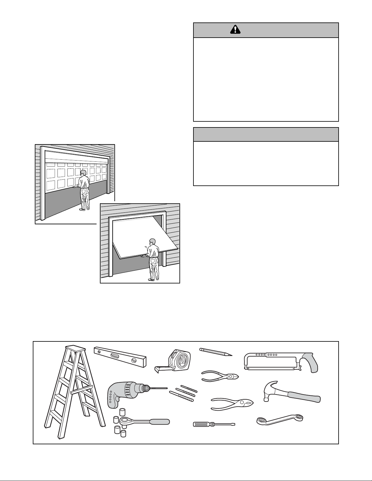
Preparing your garage door
Before you begin:
• Disable locks.
•Remove any ropes connected to garage door.
• Complete the following test to make sure your
garage door is balanced and is not sticking or
binding:
1. Lift the door about halfway as shown. Release
the door.If balanced, it should stay in place,
supported entirely by its springs.
2. Raise and lower the door to see if there is any
binding or sticking.
If your door binds, sticks, or is out of balance, call
a trained door systems technician.
Tools needed
During assembly, installation and adjustment of the
opener, instructions will call for hand tools as
illustrated below.
WARNING
WARNING
WARNING
WARNING
Sectional Door
One-Piece Door
WARNING
CAUTION
Carpenter's
Level
Drill
2
1
Tape Measure
3/16", 5/16" and
5/32" Drill Bits
Pencil
Hack Saw
Wire Cutters
Claw Hammer
Pliers
Stepladder
1/2", 5/8", 7/16", 9/16"
& 1/4" Sockets and Wrench
Screwdriver
Box Wrench 1/2 x 7/16"
Page 4
4
SECTIONAL DOOR INSTALLATION
Planning
Identify the type and height of your garage door.
Survey your garage area to see if any of the
conditions below apply to your installation.Additional
materials may be required.You may find it helpful to
refer back to this page and the accompanying
illustrations as you proceed with the installation of
your opener.
Depending on your requirements, there are several
installation steps which may call for materials or
hardware not included in the carton.
• Installation Step 1 – Look at the wall or ceiling
above the garage door.The header bracket must
be securely fastened to structural supports.
• Installation Step 6 – Do you have a finished ceiling
in your garage? If so, a suppor t bracket and
additional fastening hardware may be required.
• Installation Step 4 – Depending upon garage
construction, extension brackets or wood blocks
may be needed to install sensors.
• Installation Step 4 – Alternate floor mounting of the
safety reversing sensor will require hardware not
provided.
• Do you have an access door in addition to the
garage door? If not, Model 53702 Emergency Key
Release is required. See Accessories page.
• Look at the garage door where it meets the floor.
Any gap between the floor and the bottom of the
door must not exceed 1/4" (0.625 cm).Otherwise,
the safety reversal system may not work properly.
See Adjustment Step 3. Floor or door should be
repaired.
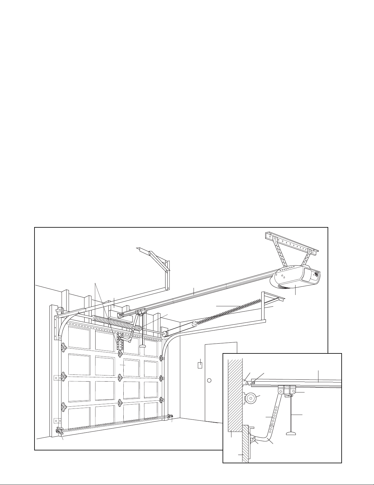
SECTIONAL DOOR INSTALLATIONS
• Do you have a steel, aluminum, fiberglass or glass
panel door? If so, horizontal and vertical reinforcement is required (Installation Step 12).
• The opener should be installed above the center of
the door.If there is a torsion spring or center
bearing plate in the way of the header bracket, it
may be installed within 4 feet (1.20 m) to the left or
right of the door center.See Installation Steps 1
and 12.
• If your door is more than 7 feet (2.10 m) high, see
rail extension kits listed on Accessories page.
Horizontal and vertical reinforcement
is needed for lightweight garage doors
(fiberglass, steel, aluminum, door with
glass panels, etc.). See page 24 for details.
Header Wall
— — — — — — — —
Door
Center
Gap between floor
and bottom of door
Safety Reversing Sensor
must not exceed
1/4" (0.625 cm)
Torsion
Spring
Safety
Reversing
Sensor
Rail
OR
Wallmounted
Door
Control
Extension
Spring
Access
Door
FINISHED CEILING
Support bracket &
fastening hardware
is required.
See page 20
Header
Bracket
Straight
Door
Arm
Header
Wall
Garage
Door
Door
Bracket
CLOSED POSITION
Rail
Bracket
Garage
Door
Spring
Curved
Door
Arm
Motor unit
Rail Assembly
Trolley
Emergency
Release
Rope & Handle
Page 5
5
Planning (Continued)
ONE-PIECE DOOR INSTALLATIONS
• Generally, a one-piece door does not require
reinforcement. If your door is lightweight, refer to
the information relating to sectional doors in
Installation Step 12.
• Depending on your door’s construction, you may
need additional mounting hardware for the door
bracket (Step 12).
ONE-PIECE DOOR WITHOUT TRACK
ONE-PIECE DOOR WITH TRACK
Without a properly working safety reversal system,
persons (particularly small children) could be
SERIOUSLY INJURED or KILLED by a closing garage
door.
• The gap between the bottom of the garage door and
the floor MUST NOT exceed 1/4" (0.625 cm).
Otherwise, the safety reversal system may not work
properly.
• The floor or the garage door MUST be repaired to
eliminate the gap.
WARNING
WARNING
Header Wall
Safety Reversing
Sensor
Safety Reversing
Sensor
Gap between floor
and bottom of door
must not exceed
1/4" (0.625 cm)
FINIS
Support bracket
& fastening
hardw
See page 20.
Rail
Access
Door
HED
CEILING
are is
required.
Wall-mounted
Door Control
Motor unit
Header
Wall
Rail
Bracket
Header
Bracket
Door
Bracket
Garage
Door
CLOSED POSITION
Trolley
Straight
Door
Arm
Curved
Door
Arm
Rail Assembly
Emergency
Release
Rope & Handle
Gap between floor
Safety
Reversing Sensor
and bottom of door
must not exceed
1/4" (0.625 cm)
Access
Door
Safety
Reversing
Sensor
Header
Wall
Garage
Door
CLOSED POSITION
Rail
Bracket
Header
Bracket
Door
Bracket
Curved
Door Arm
Trolley
Straight
Door
Arm
Emergency Release
Rope & Handle
Rail Assembly
Page 6
6
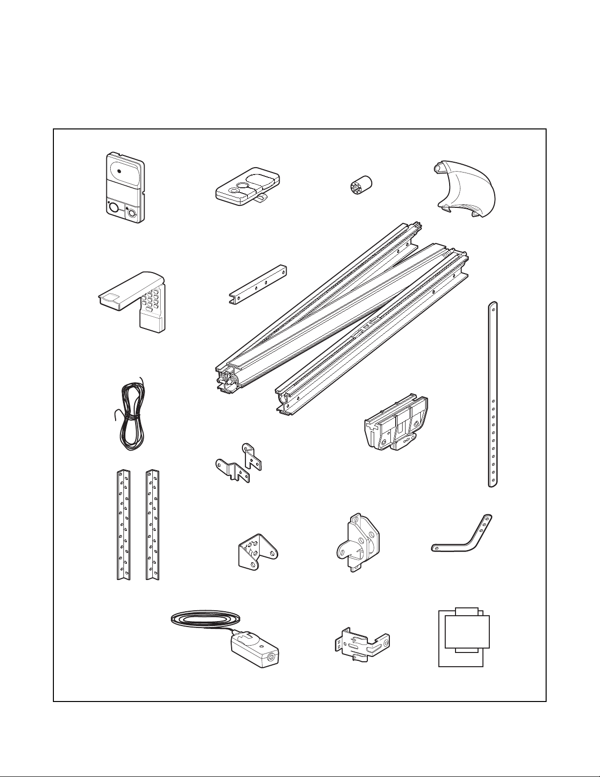
Your garage door opener is packaged in one carton
which contains the motor unit and the parts illustrated
below. Note that accessories will depend on the
model purchased. If anything is missing, carefully
check the packing material. Parts may be stuck in the
foam. KEEP THE FOAM INTACT (see page 10.)
Hardware for assembly and installation is shown on
the next page.Save the carton and packing material
until installation and adjustment is complete.
Carton Inventory
L
IG
H
T
L
O
C
K
SECURITY✚
Premium Control Console
SECURITY✚
Keyless Entry
Three-Function Remote Control
with Visor Clip (2)
Rail Support
Braces (4)
Sprocket
Coupling
Light Lens
Rail
Assembly
2-Conductor Bell Wire
White & White/Red
Hanging Brackets
(2) Safety Reversing Sensors
(1 Sending Eye and 1 Receiving Eye)
with attached 2-Conductor
White & White/Black Bell Wire
Header/Rail
Brackets
Y
L
N
O
T
N
U
O
M
G
N
I
L
I
E
C
P
U
Header Bracket
Door Bracket
Safety Reversing Sensor
Mounting Bracket (2)
Trolley
Straight Door
Arm Section
Curved Door
Arm Section
Safety Labels
and
Literature
Page 7
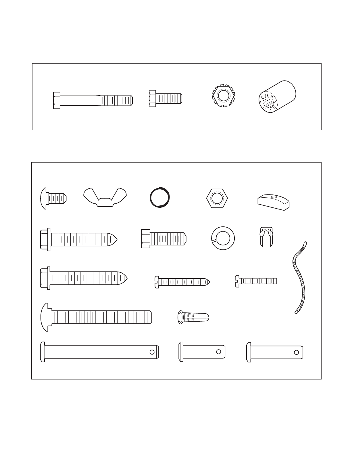
Hardware Inventory
Separate all hardware and group as shown below for the assembly and installation procedures.
7
ASSEMBLY HARDWARE
INSTALLATION HARDWARE
Carriage Bolt
1/4"-20x1/2" (2)
Lag Screw
5/16"-9x1-5/8" (2)
Bolt
1/4-20x1-3/4" (8)
Wing Nut
1/4"-20 (2)
Hex Bolt
1/4" - 20 x 5/8" (4)
Ring
Fastener (3)
Hex Bolt
5/16"-18x7/8" (4)
Nut 5/16"-18 (6)
Lock Washer 5/16" (6)
Lock Nut
1/4"-20 x 7/16 (12)
Sprocket Coupling Sleeve
Handle
Insulated
Staples (30)
Lag Screw
5/16"-18x1-7/8" (2)
Carriage Bolt
5/16"-18x2-1/2" (2)
Clevis Pin
5/16"x2-3/4" (1)
Screw
6ABx1-1/4" (2)
Dry Wall Anchors (2)
Clevis Pin
5/16"x1" (1)
Screw 6-32x1" (2)
Rope
Clevis Pin
5/16"x1-1/4" (1)
Page 8
8
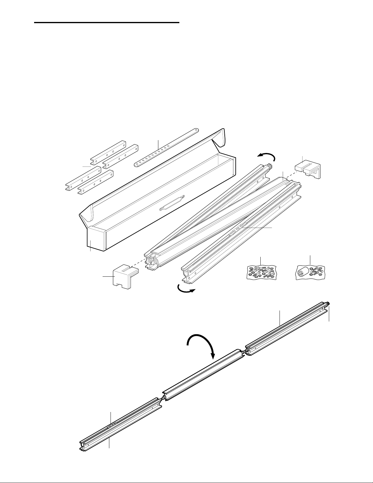
ASSEMBLY STEP 1
Assemble the Rail
To avoid installation difficulties, do not run the
garage door opener until instructed to do so.
1.Turn the opened rail car ton upside down and
empty its contents onto a level work surface.
2.Unfold the rails, taking care to avoid kinking the
screw rod joints.
3.Rotate the rail sections so that the flat side is down
and the screw side is up for all three lengths.Keep
it clean and free of debris while you are working.
NOTE: During assembly, avoid pulling the rail section
housing the trolley rack away from the screw rod.The
rack is factory set about 9" (23 cm) from the end of
the screw rod to the center of the rack.
If the plastic liner slides part way out during
assembly, simply push it back in.
Straight
Door Arm
Rail
Support
Braces
Rail Assembly
Carton
Remove
Cardboard
Packing
Extend
End Rails
Outward
Rotate
Extend
End Rails
Outward
Rail Assembly
Hardware Bag
Remove
Cardboard Packing
Center
Rail
Trolley Rack
Sprocket End Rail
Chassis Assembly
Hardware Bag
Rail
Sprocket
Trolley Rack
Door End Rail
Center Rail
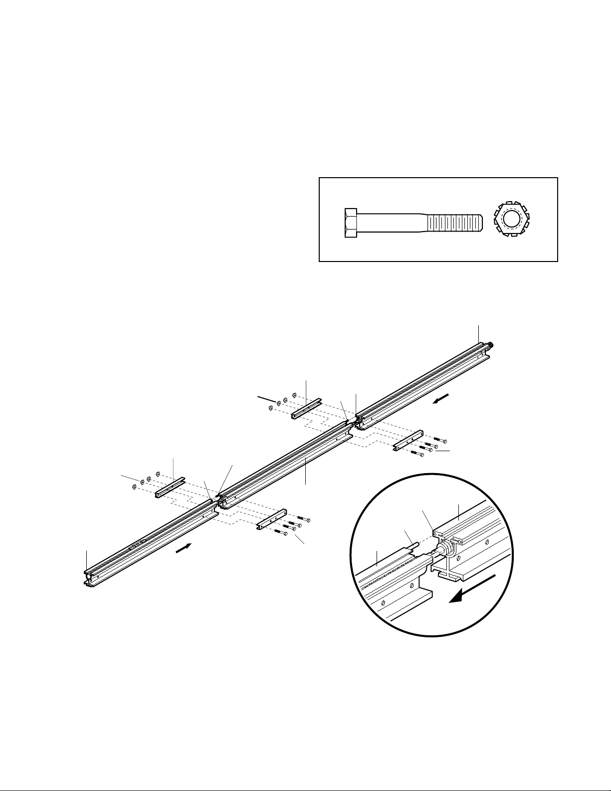
Page 9
9
Assemble the Rail (Continued)
4.Beginning with the sprocket end, straighten the
three rail sections so that the screw rod is in a
straight line at the joints. (Avoid handling the joints,
which may have sharp edges.)
5.Carefully slide the pins at the top edge of the rail
into the openings on the adjacent rail. It is
essential that the rail assembly be on a level
surface to achieve proper alignment and to
avoid damage to the pins.
6.Inser t two 1/4"-20x1-3/4" bolts through the center
holes of a brace, and place its open length against
the rail at the joint, aligning the holes as shown.
Position another brace on the opposite side of the
rail over the bolts, add 1/4"-20 lock nuts, and hand
tighten. Inser t two additional bolts and hand
tighten.
7.Keeping the rail straight and on a level surface,
grasp the screw rods on each side of the
remaining joint and pivot into a straight line.
Repeat steps 5 and 6.
8.With a 7/16 wrench, tighten bolts until snug,
beginning with the center holes. Do not
overtighten.
Center Rail
Slide end rail
toward center rail
Rail
Support
Brace
Lock
Nuts
Center
Rail
Rail Pin
Alignment
Hole
Rail
Support
Brace
Rail Pin
Rail Pin
Alignment
Hole
Alignment
Hole
Bolts
1/4"-20x1-3/4"
Bolts
1/4"-20x1-3/4"
Lock
Nuts
End
Rail
Door End
(Front)
Sprocket End
(Back)
Slide end rail
toward center rail
HARDWARE SHOWN ACTUAL SIZE
Bolt
1/4"-20x1-3/4" (8)
Lock Nut
1/4"-20
Page 10
10
Rail
Sprocket
Rail
Assembly
Trolley
Coupling
Motor Unit
Bracket
Lock Nuts
1/4"-20
Motor Unit
Sprocket
Foam Packaging
Hex Bolts
1/4"-20x5/8"
Release arm
Arrow must point
toward garage door
HARDWARE SHOWN ACTUAL SIZE
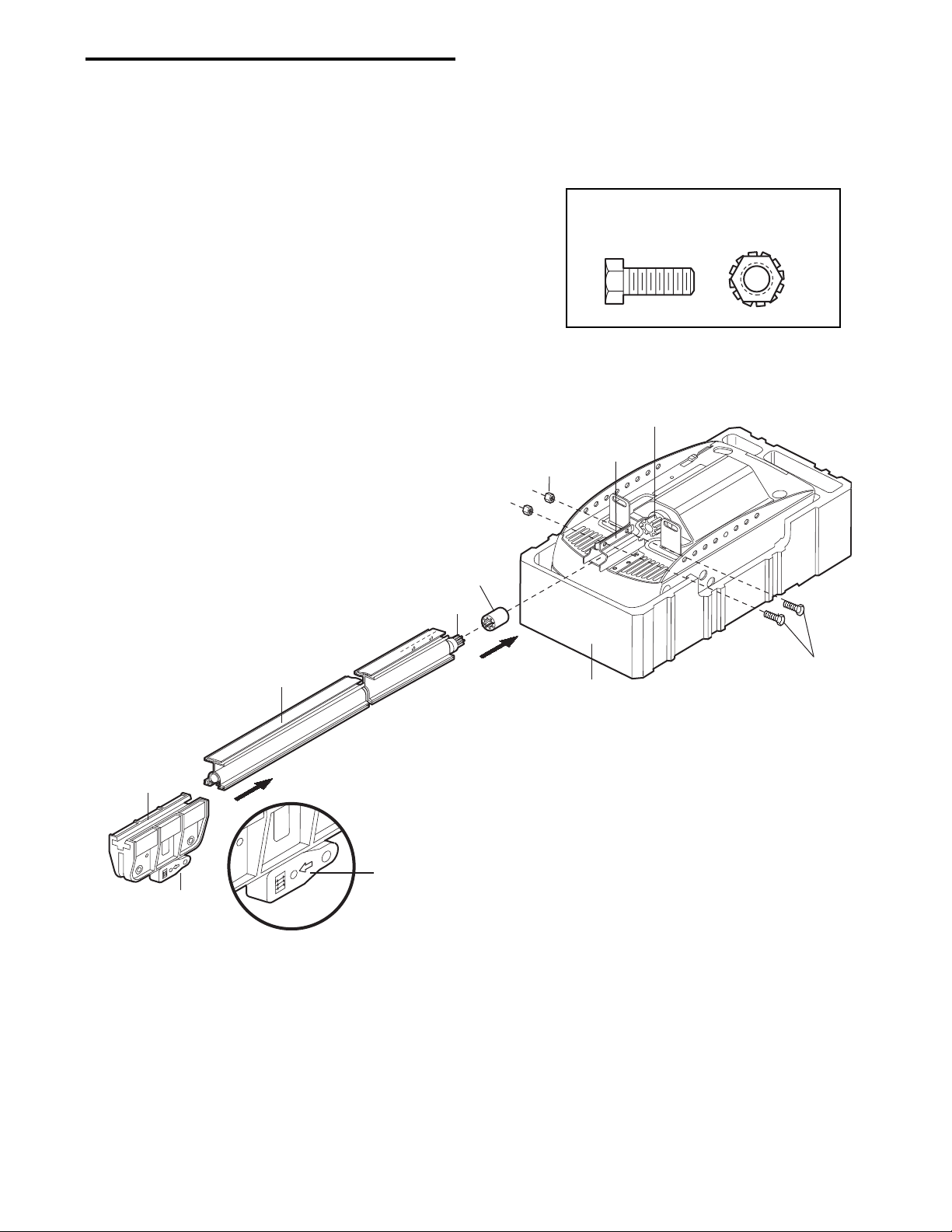
ASSEMBLY STEP 2
Fasten the Rail To the Motor Unit and Install the Trolley
NOTE: To aid in assembly and installation, replace
the foam packing around the motor unit.Remove it
after Installation Step 5.
•Working on a level surface, align the rail assembly
with the motor unit, as shown.
• Slip the coupling over the rail sprocket.
• Slide the rail through the motor unit bracket until
the coupling fits securely over the motor unit
sprocket.
• Align the two bolt holes in the rail with those in the
motor unit bracket.Insert two 1/4"-20x5/8" hex
bolts and lock nuts.Tighten securely with a 7/16"
socket wrench.
• Slide the trolley onto and along the bottom of the
rail until it snaps firmly in place. Be certain to
install it facing correctly: the trolley release
arm must be horizontal (lock position), with its
arrow pointed away from the motor unit.
Hex Bolt
1/4" - 20 x 5/8"
Lock Nut
1/4" - 20
Page 11
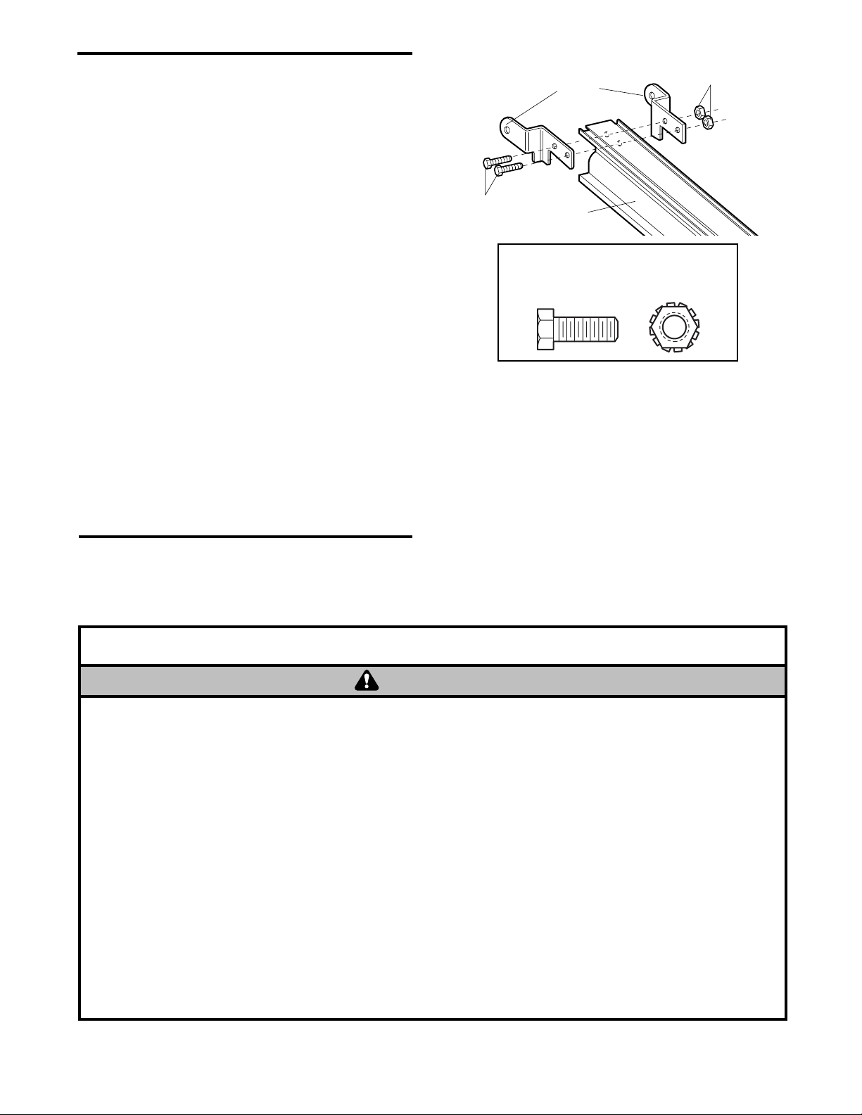
ASSEMBLY STEP 3
Attach the Rail Brackets
• Align rail brackets to end of rail assembly, as
shown.
• Insert two 1/4"-20 x 5/8" hex bolts and lock nuts.
Tighten securely with a 7/16" socket.
You have now finished assembling your garage
door opener. Please read the following warnings
before proceeding to the installation section.
11
HARDWARE SHOWN ACTUAL SIZE
INSTALLATION
IMPORTANT INSTALLATION INSTRUCTIONS
1. READ AND FOLLOW ALL INSTALLATION WARNINGS
AND INSTRUCTIONS.
2. Install garage door opener only on properly balanced
and lubricated garage door. An improperly balanced
door may not reverse when required and could result in
SEVERE INJURY or DEATH.
3. All repairs to cables, spring assemblies and other
hardware MUST be made by a trained door systems
technician BEFORE installing opener.
4. Disable all locks and remove all ropes connected to
garage door BEFORE installing opener to avoid
entanglement.
5. Install garage door opener 7 feet or more above floor.
6. Mount emergency release handle 6 feet above floor.
7. NEVER connect garage door opener to power source
until instructed to do so.
8. NEVER wear watches, rings or loose clothing while
installing or servicing opener. They could be caught in
garage door or opener mechanisms.
9. Install wall-mounted garage door control:
• within sight of the garage door
• out of reach of children at minimum height of 5 feet
• away from all moving parts of the door.
10. Place entrapment warning label on wall next to garage
door control.
11. Place manual release/safety reverse test label in plain
view on inside of garage door.
12. Upon completion of installation, test safety reversal
system. Door MUST reverse on contact with a oneinch high object (or a 2x4 laid flat) on the floor.
To reduce the risk of severe injury or death:
WARNING
Rail
Brackets
Lock Nuts
1/4"-20
Hex
Bolts
1/4"-20x5/8
Rail
Hex Bolt
1/4" - 20 x 5/8"
Lock Nut
1/4" - 20
WARNING
Page 12
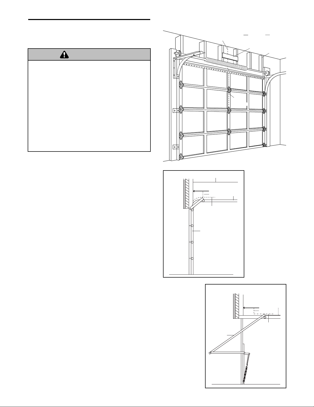
12
INSTALLATION STEP 1
Determine the Header Bracket Location
Installation procedures vary according to garage door
types. Follow the instructions which apply to your
door.
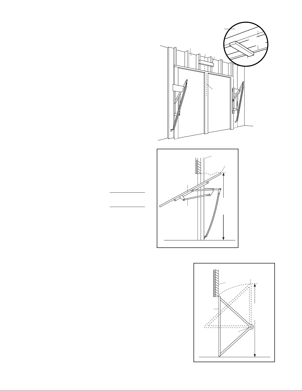
SECTIONAL DOOR
AND ONE-PIECE DOOR WITH TRACK
1.Close the door and mark the inside ver tical
centerline of the garage door.
2.Extend the line onto the header wall above the
door.
You can fasten the header bracket within 4 feet
(1.20 m) of the left or right of the door center
only if a torsion spring or center bearing plate
is in the way; or you can attach it to the ceiling
(see page 14) when clearance is minimal. (It
may be mounted on the wall upside down if
necessary, to gain approximately (1 cm) 1/2".)
If you need to install the header bracket on a 2x4
(on wall or ceiling), use lag screws (not provided)
to securely fasten the 2x4 to structural supports as
shown here and on page 13.
3.Open your door to the highest point of travel as
shown. Draw an intersecting horizontal line on the
header wall 3" (7.5 cm) above the high point.This
height will provide travel clearance for the top edge
of the door.
NOTE: Door clearance brackets are available for
sectional doors when headroom clearance is less
than 2" (5 cm). See accessor y page 39.
Proceed to Step 2, page 14.
One-piece
door with
horizontal
track
To prevent possible SERIOUS INJURY or DEATH:
• Header bracket MUST be RIGIDLY fastened to
structural support on header wall or ceiling, otherwise
garage door might not reverse when required. DO NOT
install header bracket over drywall.
• Concrete anchors MUST be used if mounting header
bracket or 2x4 into masonry.
• NEVER try to loosen, move or adjust garage door,
springs, cables, pulleys, brackets, or their hardware, all
of which are under EXTREME tension.
• ALWAYS call a trained door systems technician if
garage door binds, sticks, or is out of balance. An
unbalanced garage door might not reverse when
required.
Sectional door
with curved
track
WARNING
WARNING
Header
Wall
Vertical
Centerline
Ceiling
Vertical
Centerline
Finished
Ceiling
2x4
Structural
Supports
Header Wall
3" (7.5 cm)
Highest Point
of Travel
Door
Door
Track
Header Wall
3" (7.5 cm)
Highest Point
of Travel
Track
Page 13
13
One-piece door without track:
pivot hardware
One-piece door without track:
jamb hardware
EXAMPLE
Distance from top of door
(at highest point of travel) to floor . . . . . .92" (2.30m)
Actual height of door . . . . . . . . . . . . . .-88" (2.20 m)
Remainder . . . . . . . . . . . . . . . . . . . . . . . .4" (0.10 m)
Add . . . . . . . . . . . . . . . . . . . . . . . . . . . .+8" (0.20 m)
Bracket height on header wall . . . . . .= 12" (0.30 m)
(Measure UP from top of CLOSED door.)
Proceed to Step 2, page 14.
ONE-PIECE DOOR WITHOUT TRACK
1.Close the door and mark the inside ver tical
centerline of your garage door.Extend the line
onto the header wall above door, as shown.
If headroom clearance is minimal, you can install
the header bracket on the ceiling.See page 14.
If you need to install the header bracket on a 2x4
(on wall or ceiling), use lag screws (not provided)
to securely fasten the 2x4 to structural supports
as shown.
2.Open your door to the highest point of travel as
shown. Measure the distance from the top of the
door to the floor.Subtract the actual height of the
door.Add 8" (20 cm) to the remainder.(See
Example).
3.Close the door and draw an intersecting horizontal
line on the header wall at the determined height.
NOTE: If the total number of inches exceeds the
height available in your garage, use the maximum
height possible, or refer to page 14 for ceiling
installation.
Header Wall
Door
Jamb
Hardware
Vertical
Centerline
Header Wall
Unfinished
Ceiling
2x4
Vertical
Centerline
of Garage
Door
Highest Point
of Travel
Distance
Structural
Supports
2x4
OPTIONAL
CEILING MOUNT
FOR
HEADER BRACKET
Door
Floor
Header Wall
Pivot
Highest Point
of Travel
Distance
Floor
Page 14
14
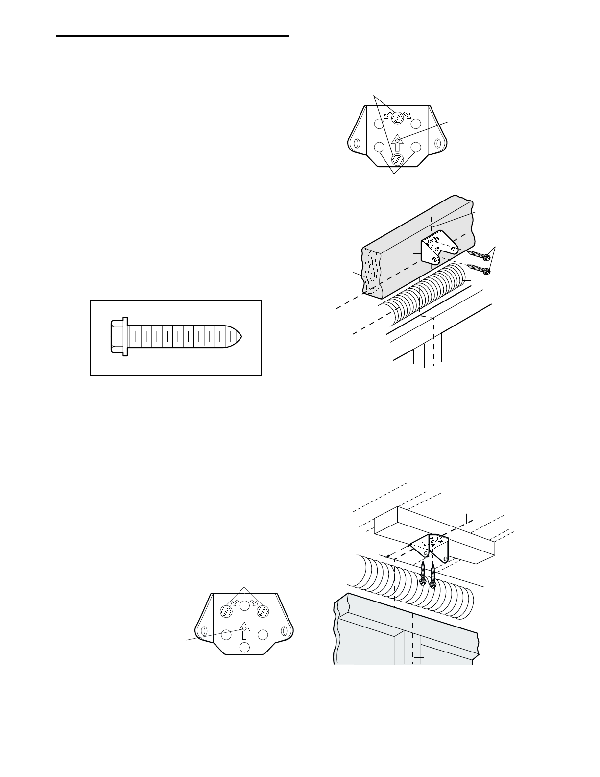
INSTALLATION STEP 2
Install the Header Bracket
You can attach the header bracket either to the wall
above the garage door, or to the ceiling. Follow the
instructions which will work best for your particular
requirements. Do not install the header bracket
over drywall. If installing into masonry, use
concrete anchors (not provided).
WALL HEADER BRACKET INSTALLATION
• Center the bracket on the vertical centerline with
the bottom edge of the bracket on the horizontal
line as shown (with the arrow pointing toward the
ceiling).
• Mark the vertical set of bracket holes (do not use
the holes designated for ceiling mount). Drill 3/16"
pilot holes and fasten the bracket securely to a
structural support with the hardware provided.
HARDWARE SHOWN ACTUAL SIZE
UP
CEILING MOUNT ONLY
Ceiling Mounting Holes
The nail hole is for
positioning only.
You must use lag screws
to mount the header bracket.
U
P
Lag Screws
5/16"-9x1-5/8"
Garage Door
Vertical Centerline
Header Wall
– Finished Ceiling –
Header
Bracket
6" (15 cm)
Maximum
Vertical
Centerline
Door
Spring
CEILING HEADER BRACKET INSTALLATION
• Extend the vertical centerline onto the ceiling as
shown.
• Center the bracket on the vertical mark, no more
than 6" (15 cm) from the wall. Make sure the arrow
is pointing toward the wall. The bracket can be
mounted flush against the ceiling when clearance
is minimal.
• Mark the side holes. Drill 3/16" pilot holes and
fasten bracket securely to a structural support with
the hardware provided.
Lag Screw
5/16"-9 x 1-5/8"
Wall Mounting Holes
CEILING MOUNT ONLY
Optional
Wall Mounting Holes
Header
Wall
2x4
Structural
Support
Highest Point of
Garage Door Travel
UP
Header
Bracket
The nail hole is for
positioning only.
You must use lag screws
to mount the header bracket.
Vertical
Centerline
Y
L
N
O
T
N
U
O
M
G
IN
IL
E
C
UP
Door Spring
Garage
Door
Vertical
Centerline
Lag Screws
5/16"x9x1-5/8"
Page 15
15
Header Wall
Clevis Pin
5/16"x2-3/4"
Ring Fastener
HARDWARE SHOWN ACTUAL SIZE
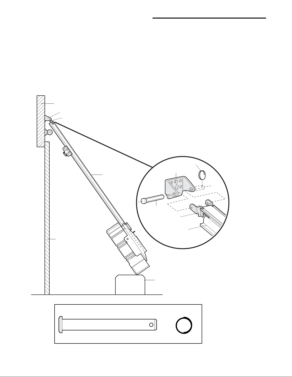
INSTALLATION STEP 3
Attach the Rail to the Header Bracket
• Position the opener on the garage floor below the
header bracket.Use packing material as a
protective base. NOTE: If the door spring is in the
way you’ll need help. Have someone hold the
opener securely on a temporary support to allow
the rail to clear the spring.
• Position the rail bracket against the header bracket.
• Align the bracket holes and join with a clevis pin
as shown.
• Insert a ring fastener to secure.
Header Bracket
Rail Bracket
Garage
Door
Rail
Clevis Pin
5/16"x2-3/4"
Temporary
Support
Ring Fastener
Header Bracket
Rail
Bracket
Rail
Page 16
16
Facing the door from inside the garage
INSTALLATION STEP 4
Install the Safety Reversing Sensor
The safety reversing sensor must be connected
and aligned correctly before the garage door
opener will move in the down direction.
IMPORTANT INFORMATION ABOUT
THE SAFETY REVERSING SENSOR
When properly connected and aligned, the sensor
will detect an obstacle in the path of its electronic
beam.The sending eye (with an orange indicator
light) transmits an invisible light beam to the
receiving eye (with a green indicator light).If an
obstruction breaks the light beam while the door is
closing, the door will stop and reverse to full open
position, and the opener lights will flash 10 times.
The units must be installed inside the garage so that
the sending and receiving eyes face each other
across the door, no more than 6" (15 cm) above the
floor.Either can be installed on the left or right of the
door as long as the sun never shines directly into the
receiving eye lens.
The mounting brackets are designed to clip onto the
track of sectional garage doors without additional
hardware.
If it is necessary to mount the units on the wall, the
brackets must be securely fastened to a solid
surface such as the wall framing.Extension brackets
(see accessories) are available if needed.If installing
in masonry construction, add a piece of wood at
each location to avoid drilling extra holes in masonr y
if repositioning is necessary.
The invisible light beam path must be unobstructed.
No part of the garage door (or door tracks, springs,
hinges, rollers or other hardware) may interrupt the
beam while the door is closing.
• Be sure power is not connected to the garage door
opener BEFORE installing the safety reversing sensor.
• To prevent SERIOUS INJURY or DEATH from a closing
garage door:
– Correctly connect and align the safety reversing
sensor. This required safety device MUST NOT be
disabled.
– Install the safety reversing sensor so beam is NO
HIGHER than 6" (15 cm) above garage floor.
WARNING
WARNING
Sensor Beam
6" (15 cm) max.
above floor
Invisible Light Beam
Protection Area
Sensor Beam
6" (15 cm) max.
above floor
Page 17
17
Figure 3
Figure 1
Figure 2
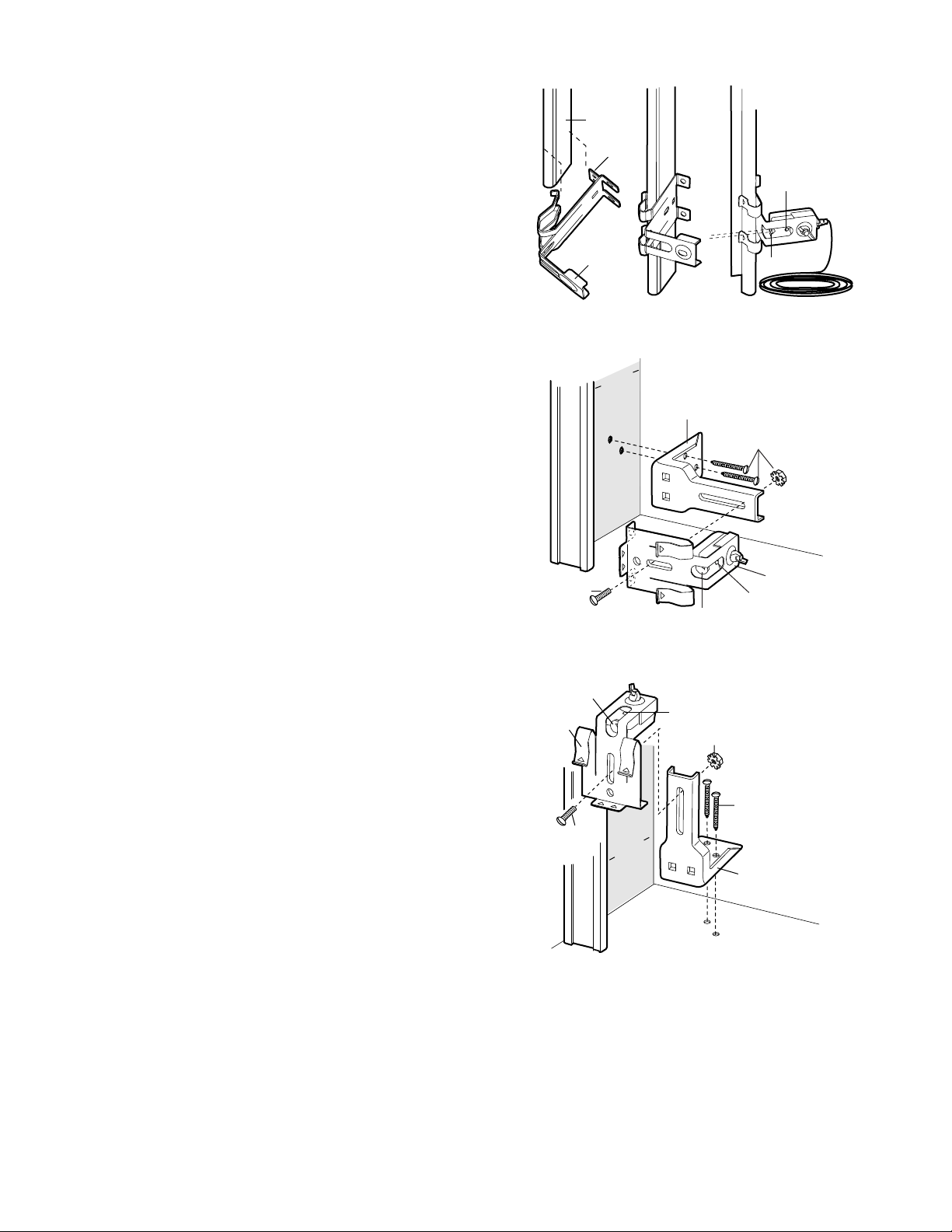
INST ALLING THE BRA CKETS
Be sure power to the opener is disconnected.
Install and align the brackets so the sensors will face
each other across the garage door, with the beam no
higher than 6" (15 cm) above the floor.They may be
installed in one of three ways, as follows.
Garage door track installation (preferred):
• Slip the curved arms over the rounded edge of
each door track, with the curved arms facing the
door.Snap into place against the side of the track.
It should lie flush, with the lip hugging the back
edge of the track, as shown in Figure 1.
If your door track will not support the bracket
securely, wall installation is recommended.
Wall installation:
• Place the bracket against the wall with cur ved arms
facing the door. Be sure there is enough clearance
for the sensor beam to be unobstructed.
• If additional depth is needed, an extension bracket
(see Accessories) or wood blocks can be used.
• Use bracket mounting holes as a template to locate
and drill (2) 3/16" diameter pilot holes on the wall at
each side of the door, no higher than 6" (15 cm)
above the floor.
• Attach brackets to wall with lag screws
(not provided).
• If using extension brackets or wood blocks, adjust
right and left assemblies to the same distance out
from the mounting surface.Make sure all door
hardware obstructions are cleared.
Floor installation:
• Use wood blocks or extension brackets (see
Accessories) to elevate sensor brackets so the
lenses will be no higher than 6" (15 cm) above the
floor.
• Carefully measure and place right and left
assemblies at the same distance out from the wall.
Be sure all door hardware obstructions are cleared.
• Fasten to the floor with concrete anchors as shown.
(Provided with
Extension
Bracket)
Sensor
Bracket
(Provided with
Extension
Bracket)
DOOR TRACK MOUNT (RIGHT SIDE)
Door
Track
Lip
Sensor
Bracket
WALL MOUNT (RIGHT SIDE)
Lens
Inside
arage
G
W
Extension
Bracket
all
(See Accessories)
Lens
FLOOR MOUNT (RIGHT SIDE)
Indicator
light
Inside
arage
G
all
W
Indicator
light
Lens
(Provided with
Extension Bracket)
Sensor
Bracket
Indicator
light
(Provided with
Extension Bracket)
Attach with
concrete anchors
(not provided)
Extension
Bracket
(See Accessories)
Page 18
18
Figure 4
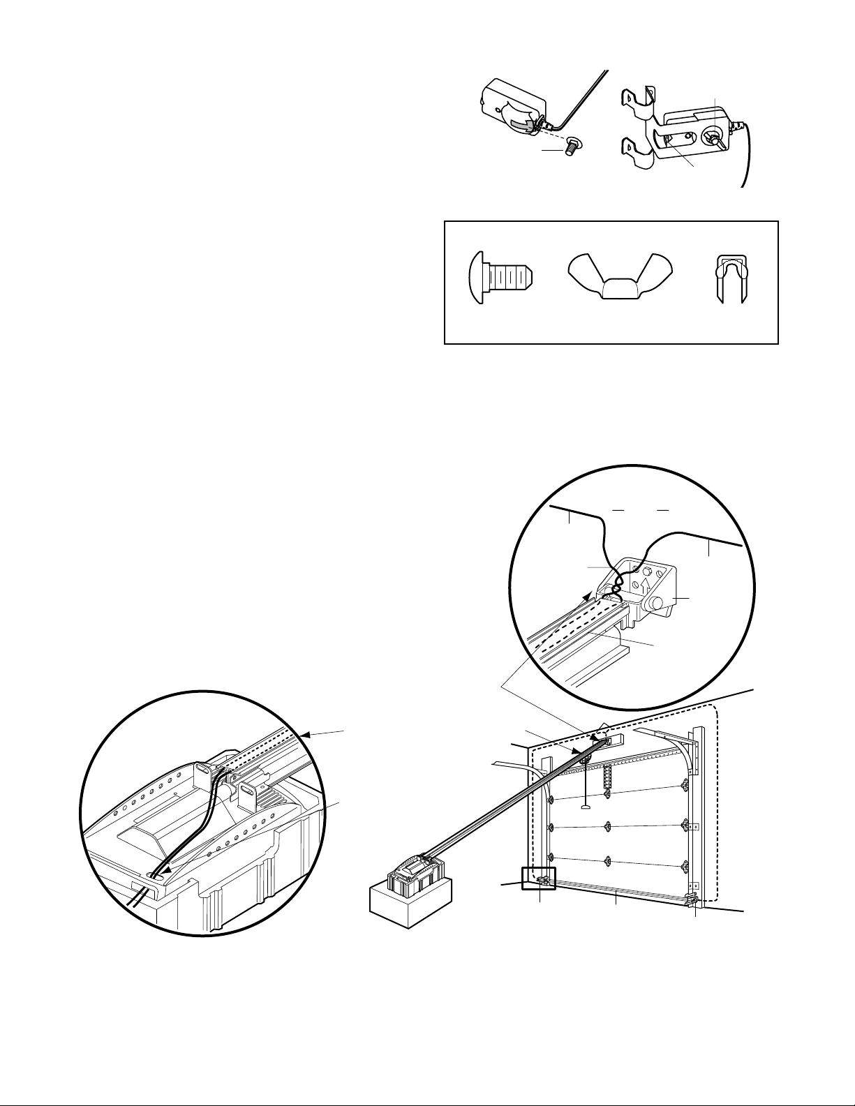
MOUNTING AND WIRING THE SAFETY SENSORS
• Slide a 1/4"-20x1/2" carriage bolt head into the slot
on each sensor.Use wing nuts to fasten sensors to
brackets, with lenses pointing toward each other
across the door.Be sure the lens is not obstructed
by a bracket extension. See Figure 4.
• Finger tighten the wing nuts.
Recommended Wire Routing
1.Using insulated staples, run the wires from both
sensors to the rail at the door header
(see Figure 5).
2.Cross and twist the two wires where they meet
the rail (see inset A). Run the wires inside the
channels at the top of the rail, along each side,
to the motor unit. Do not use the lower (trolley)
channels. Use a screwdriver tip to tuck the wires
snugly into the channels.
NOTE: If your access door is near the garage
door, you may choose to install the door control at
this time and run the door control wire along the
rail with the sensor wires. Use one rail channel for
the door control wire and the other channel for
both sensor wires. If you choose this option, follow
instructions 1-3 on page 21 now.
3.Pull wires taut across the top of the chassis and
insert into the opening above the terminal block
(see Figure 5, Illustration B).You will complete the
wiring in Installation Step 7.
HARDWARE SHOWN ACTUAL SIZE
Invisible Light Beam
Protection Area
Sensor
Sensor
Bell Wire
Header
Bracket
Header
Wall
Sensor
Wire
Twist
Wires
Sensor
Wire
Rail
Channel
2. Run wires along channels
to motor unit. Use screwdrive blade
to tuck snugly into channels.
1. Run wires from sensors to end of rail
at the door header. Cross & twist here to
help contain wires in channels on top of rail.
3. Pull wires taut across top of chassis
and insert into opening above
terminal block.
Figure 5
A
B
Carriage bolt
1/4"-20x1/2"
Carriage Bolt
1/4"-20x1/2"
Wing nut
Wing Nut
1/4"-20
Lens
Staples
Page 19
19
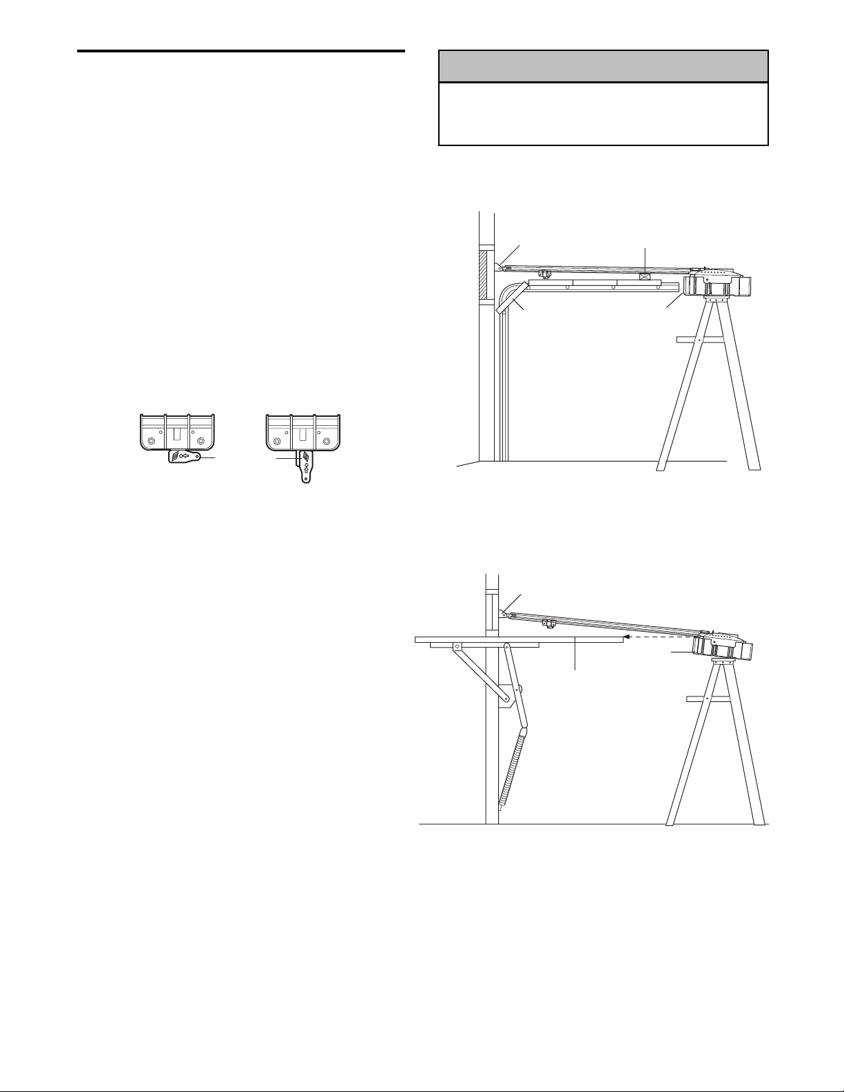
ONE-PIECE DOOR WITHOUT TRACK
•With the door fully open and parallel to the floor,
measure the distance from the floor to the top of
the door.
• Using a stepladder as a support, raise the top of
the opener to this height.
• The top of the door should be level with the top of
the motor unit. Do not position the opener more
than 3" (7.5 cm) above this point.
INSTALLATION STEP 5
Position the Opener
Follow instructions which apply to your door type as
illustrated.
SECTIONAL DOOR OR ONE-PIECE DOOR WITH
TRACK
A 2x4 laid flat is convenient for setting an ideal doorto-rail distance.
• Raise the opener onto a stepladder.You will need
help at this point if the ladder is not tall enough.
• Open the door all the way and place a 2x4 laid flat
on the top section beneath the rail.
• If the top section or panel hits the trolley when you
raise the door, pull down on the trolley release arm
to disconnect inner and outer sections. Slide the
outer trolley toward the motor unit.The trolley can
remain disconnected until Installation Step 13
is completed.
To prevent damage to garage door, rest garage door
opener rail on 2x4 (5 x 10 cm) placed on top section
of door.
WARNING
WARNING
WARNING
Trolley
Release Arm
ENGAGED
RELEASED
CAUTION
Header
Bracket
Door
2x4
Foam
Packaging
Header
Bracket
Top of Door
Foam
Packaging
Page 20
20
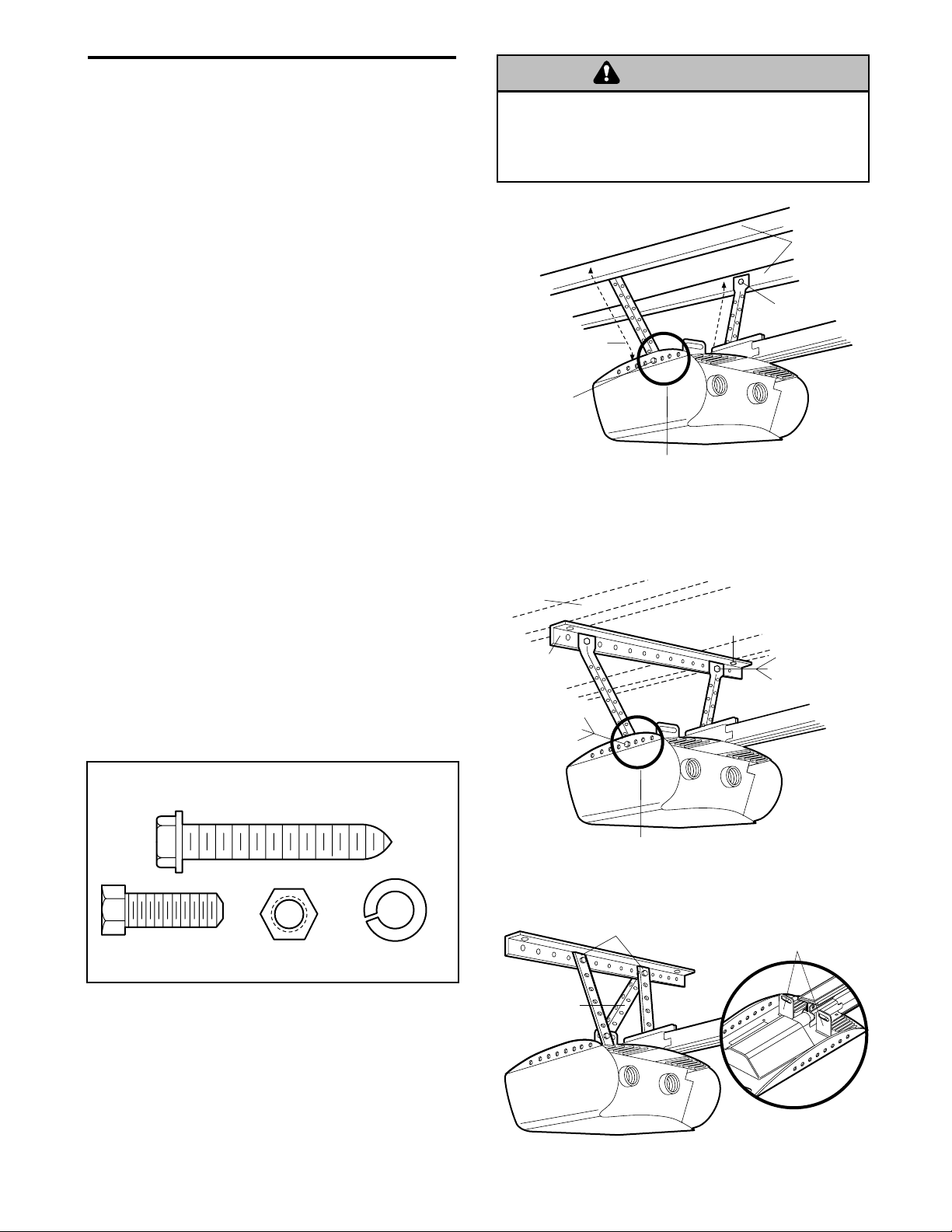
INSTALLATION STEP 6
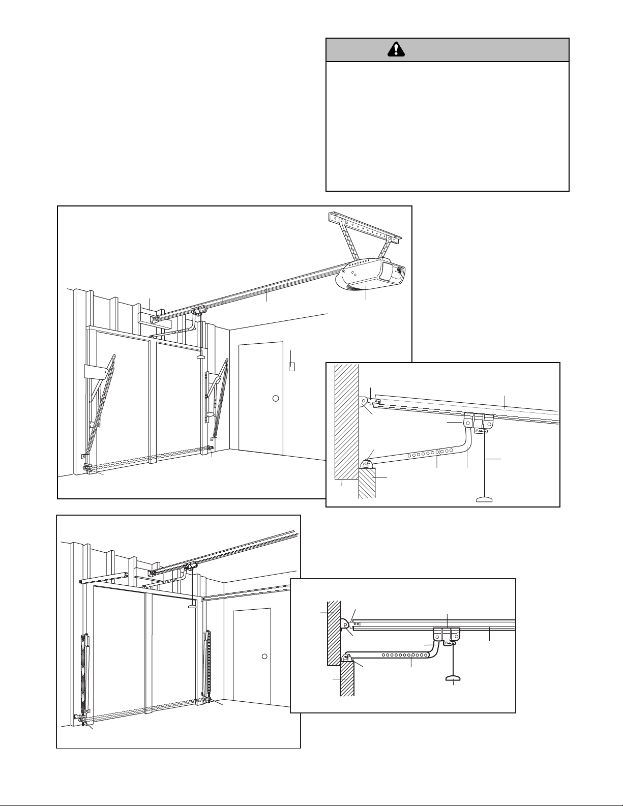
Hang the Opener
Three representative installations are shown.Yours
may be different.Hanging brackets should be angled
(Figure 1) to provide rigid support. On finished
ceilings (Figure 2), attach a sturdy metal bracket to
structural supports before installing the opener.This
bracket and fastening hardware are not provided
(see accessories).
Existing brackets from a previous installation may be
fastened to the sides of the motor unit as in
Figures 1 and 2, or to the mounting tabs as shown in
Figure 3. Then continue with step 5 below.
1. Remove foam packaging.Measure the distance
from each side of the motor unit to the structural
support.
2. Cut both pieces of the hanging bracket to required
lengths.
3. Drill 3/16" pilot holes in the structural supports.
4. Attach one end of each bracket to a support with
5/16"-18x1-7/8" lag screws.
5. Fasten the opener to the hanging brackets with
5/16"-18x7/8" hex bolts, lock washers and nuts.
If you wish to utilize the two center mounting tabs,
you must triangulate the vertical brackets for
additional stability. See Figure 3.
6. Check to make sure the rail is centered over the
door (or in line with the header bracket if the
bracket is not centered above the door).
7. Remove the 2x4. Operate the door manually. If the
door hits the rail, raise the header bracket.
To avoid possible SERIOUS INJURY from a falling
garage door opener, fasten it SECURELY to structural
supports of the garage. Concrete anchors MUST be used
if installing any brackets into masonry.
HARDWARE SHOWN ACTUAL SIZE
Figure 1
Figure 2
Figure 3
WARNING
WARNING
Measure
Distance
Hex Bolts
5/16"-18x7/8"
Lock Washers 5/16"
Nuts 5/16"-18
Hidden
Support
Bracket
(Not Provided)
Bolt 5/16"-18x7/8"
Lock Washer 5/16"
Nut 5/16"-18
Preferred range of
bracket placement
— FINISHED CEILING —
Lag Screws
5/16"-18x1-7/8"
Structural
Supports
Lag Screws
5/16"- 18x1-7/8"
(Not Provided)
Bolt 5/16"-18x7/8"
Lock Washer 5/16"
Nut 5/16"-18
Lag Screw 5/16"-18x1-7/8"
Hex Bolt
5/16"-18x7/8"
Nut 5/16"-18
Lock Washer 5/16"
Bracket
(Provided)
Preferred range of
bracket placement
Existing Brackets
Utilizing existing top mount installation
Top Mounting Tabs
Page 21
21
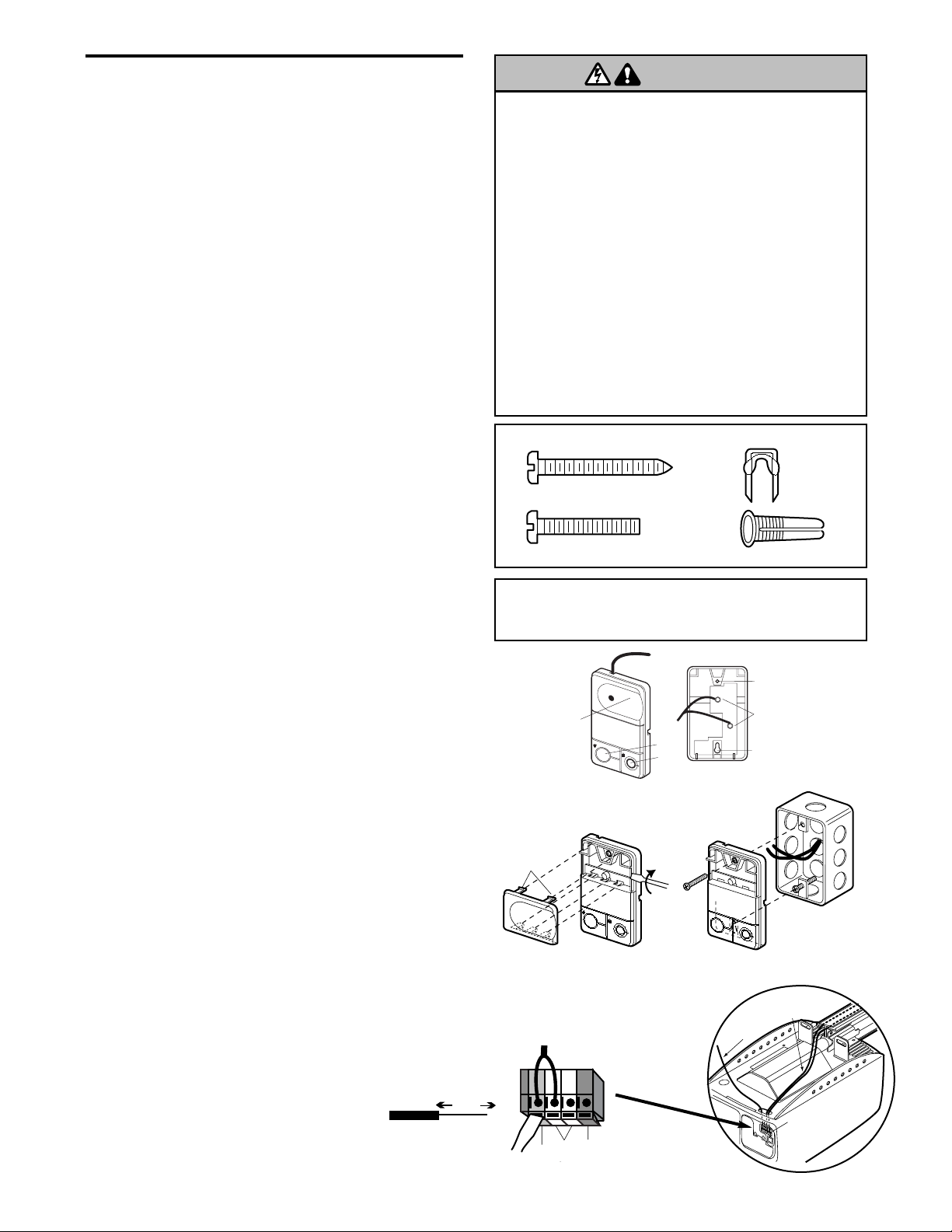
INSTALLATION STEP 7
Install the Door Control
Locate door control within sight of door, at a minimum
height of 5 feet (1.5 m) where small children cannot
reach, away from moving par ts of door and door
hardware. If installing into drywall, drill 5/32" (0.40 cm)
holes and use the anchors provided. For pre-wired
installations (as in new home construction), it may be
mounted to a single gang box (Figure 2).
1.Strip 7/16" (11 mm) of insulation from one end of
bell wire and connect to the two screw terminals on
back of door control by color: white wire to 2 and
white/red wire to the 1.
2.Remove white cover by gently prying at slot in top
of the cover with a small flat head screwdriver.
Fasten with 6AB x 1-1/4" self-tapping screws
(drywall installation) or 6-32 x 1" machine screws
(into gang box) as follows:
• Drill and install bottom screw, allowing 1/8" (3 mm)
to protrude above wall surface.
• Position bottom of door control on screw head and
slide down to secure. Adjust screw for snug fit.
• Drill and install top screw with care to avoid
cracking plastic housing. Do not over tighten.
• Insert top tabs and snap on cover.
3. (Standard installation only) Run bell wire up wall
and across ceiling to motor unit. Use insulated
staples to secure wire in several places. Do not
pierce wire with a staple, creating a short or open
circuit. If your access door is near the garage door,
you may run this wire with the Safety Reversing
Sensor wires along the top of the rail. See page 18.
4. Inser t all wires through the opening on top of motor
unit above the terminal block on the back panel
(Figure 3).
5. Strip 7/16" (11 mm) of insulation from each set of
wires. Insert door control wire into quick-connect
terminals by color: white wire to white, white/red
wire to red.
Separate white and white/black wires sufficiently to
connect to the opener quick-connect terminals.Twist
like colored wires together. Insert wires into quickconnect holes: white to white and white/black to
grey.
NOTE: When connecting multiple door controls to the
opener, twist same color wires together. Inser t wires
into quick-connect holes: white to white and red/white
to red.
6.Use tacks or staples to permanently attach
entrapment warning label to wall near door control,
and manual release/safety reverse test label in a
prominent location on inside of garage door.
NOTE: DO NOT connect the power and operate the
opener at this time. The trolley will travel
to the full open position but will not return
to the close position until the sensor
beam is connected and properly aligned.
e
Hardware Shown Actual Size
Figure 3 Wiring to Terminal Block
Strip 7/16" (11 mm) of insulation from each wire.
Insert wires through opening on top of motor
unit above terminal block, then into quickconnect terminals.
To prevent possible SERIOUS INJURY or DEATH from
electrocution:
• Be sure power is not connected BEFORE installing door
control.
• Connect ONLY to 24 VOLT low voltage wires.
To prevent possible SERIOUS INJURY or DEATH from a
closing garage door:
• Install door control within sight of garage door, out of
reach of children at a minimum height of 5 feet, and
away from all moving parts of door.
• NEVER permit children to operate or play with door
control push buttons or remote control transmitters.
• Activate door ONLY when it can be seen clearly, is properly
adjusted, and there are no obstructions to door travel.
• ALWAYS keep garage door in sight until completely
closed. NEVER permit anyone to cross path of closing
garage door.
WARNING
Outside Keylock Accessory Connections
To opener quick-connect terminals: white to white;
white/red to red.
To
Door
Control
To
Sensors
QuickConnect
Terminal
Strip wire 7/16" (11mm)
7/16"
(11mm)
WARNING
6AB x 1-1/4" Screw
(drywall installation)
6-32 x 1" Screw
(gang box installation)
PREMIUM
CONTROL
CONSOLE
WHITE
Lighted
Push
Button
LIG
H
T
L
O
Light
C
K
Lock
2
RED
1
BACK VIEW
Figure 1 Figure 2
Here
PRE-WIRED
INSTALLATION
REMOVE & REPLACE COVER
L
I
G
H
T
To Remove,
L
O
C
K
To Replace,
Insert Top
Tabs First
Twist
Door Control
Connections
To release wire, push in tab
with screwdriver tip
White
Red
Grey
Insulated
Staples
Dry Wall Anchors
Top
Mounting Hole
Terminal
Screws
Bottom
Mounting Hol
24 Volt
2-Conductor
Bell Wire in
Gang Box
Page 22
22
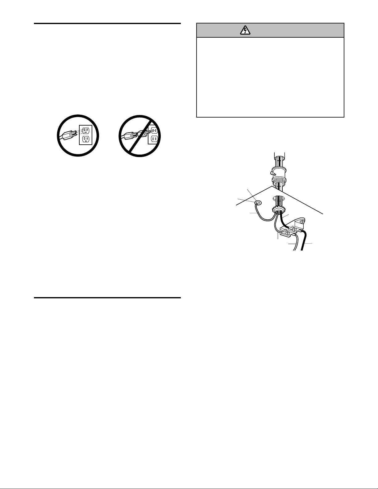
INSTALLATION STEP 8
Electrical Requirements
To avoid installation difficulties, do not run the
opener until Step 9 below.
To reduce the risk of electric shock, your garage door
opener has a grounding type plug with a third
grounding pin.This plug will only fit into a grounding
type outlet. If the plug doesn't fit into the outlet you
have, contact a qualified electrician to install the
proper outlet.
If permanent wiring is required by your local
code, refer to the following procedure.
To make a permanent connection through the 7/8"
(2.19 cm) hole in the top of the motor unit:
•Remove the motor unit cover screws and set the
cover aside.
•Remove the attached 3-prong cord.
• Connect the black (line) wire to the screw on the
brass terminal; the white (neutral) wire to the screw
on the silver terminal; and the ground wire to the
green ground screw. The opener must be
grounded.
• Reinstall the cover.
To avoid installation difficulties, do not run the
opener until Step 9 below.
INSTALLATION STEP 9
Complete the Safety Reversing Sensor Installation
ALIGNING THE SAFETY SENSORS
• Plug in the opener.The indicator lights in both the
sending and receiving eyes will glow steadily if
wiring connections and alignment are correct.
The sending eye orange indicator light will glow
regardless of alignment or obstruction. If the green
indicator light in the receiving eye is off, dim, or
flickering (and the invisible light beam path is not
obstructed), alignment is required:
• Loosen the sending eye wing nut and readjust,
aiming directly at the receiving eye.Lock in place.
• Loosen the receiving eye wing nut and adjust the
sensor until it receives the sender’s beam. When
the green indicator light glows steadily, tighten the
wing nut.
To prevent possible SERIOUS INJURY or DEATH from
electrocution or fire:
• Be sure power is not connected to the opener, and
disconnect power to circuit BEFORE removing cover to
establish permanent wiring connection.
• Garage door installation and wiring MUST be in
compliance with all local electrical and building codes.
• NEVER use an extension cord, 2-wire adapter, or
change plug in any way to make it fit outlet. Be sure
the opener is grounded.
TROUBLESHOOTING THE SAFETY SENSORS
1.If the sending eye indicator light does not glow
steadily after installation, check for:
• Electr ic power to the opener.
• A short in the white or white/black wires.These
can occur at staples, or at opener connections.
• Incorrect wiring between sensors and opener.
• A broken wire.
2.If the sending eye indicator light glows steadily but
the receiving eye indicator light doesn't:
• Check alignment.
• Check for an open wire to the receiving eye.
3.If the receiving eye indicator light is dim, realign
either sensor.
NOTE: When the invisible beam path is obstructed or
misaligned while the door is closing, the door will
reverse. If the door is already open, it will not close.
The opener lights will flash 10 times. (See page 16.)
WARNING
RIGHT
WRONG
PERMANENT WIRING
CONNECTION
Ground Tab
Green
Ground Screw
Ground Wire
White Wire
Black
Wire
Black Wire
Page 23
23
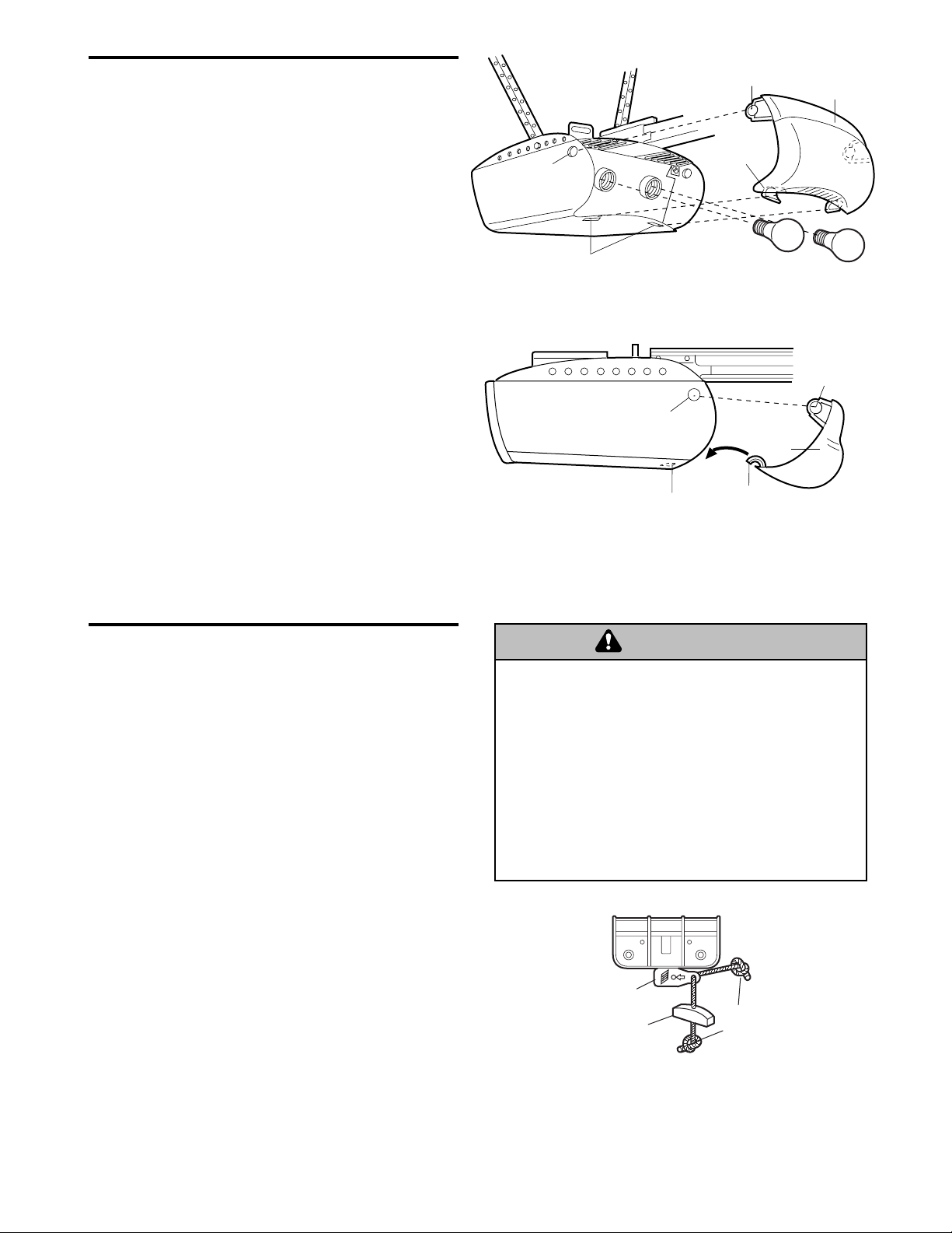
INSTALLATION STEP 10
Install the Lights and Lens
• Install a 100 watt maximum light bulb in each
socket.The lights will turn ON and remain lit for
approximately 4-1/2 minutes when power is
connected.Then the lights will turn OFF.
• Insert bottom lens tabs into slots on chassis. Tilt
towards chassis to engage top tabs, then drop
down gently into place. (See illustration.)
•To remove, depress both top lens tabs. Tilt lens
slightly outward and down, then pull out to clear
bulbs.Use care to avoid snapping off bottom lens
tabs.
NOTE: Use only standard light bulbs. The use of
short neck or speciality light bulbs may overheat the
endpanel or light socket.
INSTALLATION STEP 11
Attach the Emergency Release Rope and Handle
• Thread one end of the rope through the hole in the
top of the red handle so "NOTICE" reads right side
up as shown. Secure with an overhand knot at
least 1" (2.5 cm) from the end of the rope to
prevent slipping.
• Thread the other end of the rope through the hole
in the release arm of the outer trolley.
• Adjust rope length so the handle is 6 feet (1.8 m)
above the floor. Secure with an overhand knot.
NOTE: If it is necessary to cut the rope, heat seal the
cut end with a match or lighter to prevent unraveling.
• To prevent possible SERIOUS INJURY or DEATH from
a falling garage door:
– If possible, use emergency release handle to
disengage trolley ONLY when garage door is
CLOSED. Weak or broken springs or unbalanced
door could result in an open door falling rapidly
and/or unexpectedly.
– NEVER use emergency release handle unless garage
doorway is clear of persons and obstructions.
• NEVER use handle to pull door open or closed. If rope
knot becomes untied, you could fall.
WARNING
Top Lens Tab
Lens
Top
Chassis
Slot
Bottom
Chassis Slots
Top
Chassis Slot
Bottom
Chassis Slot
Bottom
Lens Tab
Lens
Insert Bottom
Lens Tabs First
Top
Lens Tab
WARNING
Trolley
Release Arm
Emergency
Release Handle
N
Overhand
O
TIC
E
Knot
Page 24

24
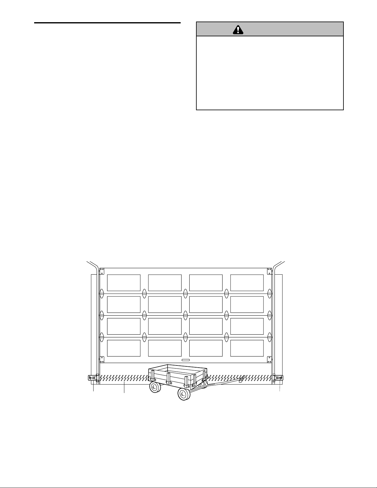
INSTALLATION STEP 12
Fasten Door Bracket
Follow instructions which apply to your door type
as illustrated below or on the following page.
A horizontal brace should be long enough to be
secured to 2 vertical supports. A vertical brace
should cover the height of the top panel.
The illustration shows one piece of angle iron as the
horizontal brace. For the vertical brace, 2 pieces of
angle iron are used to create a "U"-shaped support
(Figure 1).The best solution is to check with your
garage door manufacturer for an opener installation
door reinforcement kit.
NOTE: Many vertical brace installations provide for
direct attachment of the clevis pin and door arm. In
this case you will not need the door bracket; proceed
to Step 13.
SECTIONAL DOORS
•Center the door bracket on the previously marked
vertical centerline used for the header bracket
installation. Note correct UP placement, as
stamped inside the bracket.(Figure 2).
•Position the bracket on the face of the door within
the following limits:
A) The top edge of the bracket 2"-4" (5-10 cm)
below the top edge of the door.
B) The top edge of the bracket directly below any
structural support across the top of the door.
Vertical
Centerline
Door
Bracket
Location
Header Bracket
Horizontal and vertical reinforcement
is needed for lightweight garage doors
(fiberglass, aluminum, steel, doors with
glass panel, etc). (Not Provided)
UP
Door Bracket
Inside Edge
of Door or
Reinforcement Board
Door
Bracket
Nut
5/16"-18
Carriage Bolt
5/16"-18x2-1/2"
Lock Washer
5/16"
Vertical
Centerline
UP
Vertical
Reinforcement
HARDWARE SHOWN ACTUAL SIZE
Figure 1
Figure 2
• Mark and drill 5/16" (0.78 cm) left and right
fastening holes.Secure the bracket as shown in
Figure 1 if there is vertical reinforcement.
If your installation doesn't require vertical reinforcement but does need top and bottom fastening holes
for the door bracket, fasten as shown in Figure 2.
To prevent damage to garage door, reinforce inside of
door with angle iron both vertically and horizontally.
WARNING
WARNING
WARNING
CAUTION
Nut 5/16"-18
Lockwasher 5/16"
Carriage Bolt
5/16"-18x2-1/2"
Page 25

25
ONE-PIECE DOORS
Please read and comply with the warnings and
reinforcement instructions on the previous page.
They apply to one-piece doors also.
•Center the door bracket on the top of the door, in
line with the header bracket as shown.Mar k either
the left and right, or the top and bottom holes.
•Drill 5/16" (0.78 cm) pilot holes and fasten the
bracket with hardware supplied.
If the door has no exposed framing, drill 3/16" (0.47
cm) pilot holes and fasten the bracket with 5/16"x11/2" lag screws (not provided) to the top of the door.
NOTE: The door bracket may be installed on the top
edge of the door if required for your installation.
(Refer to the dotted line optional placement drawing.)
Drill 3/16" (0.47 cm) pilot holes and substitute
5/16"x1-1/2" lag screws (not provided) to fasten the
bracket to the door.
HARDWARE SHOWN ACTUAL SIZE
Header Wall
2x4 Support
Finished Ceiling
Nut 5/16"-18
Carriage Bolt
5/16"-18x2-1/2"
Lockwasher 5/16"
Header
Bracket
Optional
Placement
of Door
Bracket
Door
Bracket
Vertical
Centerline of
Garage Door
Horizontal and vertical
reinforcement is needed for
lightweight garage doors
(fiberglass, aluminum, steel,
door with glass panel, etc.)
(not provided).
For a door with no exposed framing,
or for the optional installation, use
5/16"x1-1/2" lag screws (not provided)
to fasten door bracket.
5/16"-18
Door
Bracket
Nut
Lock
Washer
5/16"
Top of Door
(Inside Garage)
Top Edge
of Door
Optional
Placement
Carriage Bolt
5/16"-18x2-1/2"
Page 26

26
INSTALLATION STEP 13
Connect Door Arm to Trolley
Follow instructions which apply to your door type as
illustrated below and on the following page.
SECTIONAL DOORS ONLY
•Make sure garage door is fully closed. Pull the
emergency release handle to disconnect the outer
trolley from the inner trolley. Slide the outer trolley
back (away from the door) about 2" (5 cm) as
shown in Figures 1, 2 and 3.
•Figure 1:
– Fasten straight door arm section to outer trolley
with the 5/16"x1" clevis pin. Secure the
connection with a ring fastener.
– Fasten curved section to the door bracket in the
same way, using the 5/16"x1-1/4" clevis pin.
•Figure 2:
– Bring arm sections together. Find two pairs of
holes that line up and join sections. Select holes
as far apart as possible to increase door arm
rigidity.
•Figure 3, Hole alignment alternative:
– If holes in curved arm are above holes in straight
arm, disconnect straight arm. Cut about 6" (15
cm)from the solid end. Reconnect to trolley with
cut end down as shown.
– Bring arm sections together.
– Find two pairs of holes that line up and join with
bolts, lock washers and nuts.
• Pull the emergency release handle toward the
opener at a 45° angle so that the trolley release
arm is horizontal. Proceed to Adjustment Step 1,
page 28. Trolley will re-engage automatically when
opener is operated.
Figure 1
Figure 2
Figure 3
HARDWARE SHOWN ACTUAL SIZE
Nuts
5/16"-18
Inner
Trolley
Ring
Fastener
Straight
Door Arm
Door
Bracket
Clevis Pin
5/16"x1-1/4"
Lock
Washers
5/16"
Door Bracket
Outer
Trolley
Clevis Pin
5/16"x1"
Emergency
Release
Handle
Curved Door Arm
Bolts
5/16"-18x7/8"
Nut 5/16"-18
Clevis Pin
5/16"x1" (Trolley)
Lock Washer 5/16"
Clevis Pin
5/16"x1-1/4" (Door Bracket)
Ring Fastener
Hex Bolt
5/16"-18x7/8"
Nuts
5/16"-18
Lock
Washers
5/16"
Cut this end
Bolts
5/16"-18x7/8"
Page 27

27
ALL ONE-PIECE DOORS
1.Assemble the door arm:
• Fasten the straight and curved door arm sections
together to the longest possible length (with a 2
or 3 hole overlap).
• With the door closed, connect the straight door
arm section to the door bracket with the
5/16"x1-1/4" clevis pin.
• Secure with a ring fastener.
2.Adjustment procedures:
On one-piece doors, before connecting the door
arm to the trolley, the travel limits must be
adjusted. Limit adjustment screws are located on
the left side panel as shown on page 28. Follow
adjustment procedures below.
• Open door adjustment: decrease UP
travel limit
– Turn the UP limit adjustment screw counter-
clockwise 5-1/2 turns.
– Press the Door Control push bar.The trolley
will travel to the fully open position.
– Manually raise the door to the open position
(parallel to the floor), and lift the door arm to
the trolley. The ar m should touch the trolley just
in back of the door arm connector hole. Refer
to the fully open trolley/door arm positions in
the illustration. If the arm does not extend far
enough, adjust the limit further. One full turn
equals 2" (5 cm) of trolley travel.
• Closed door adjustment: decrease DOWN
travel limit
– Turn the DOWN limit adjustment screw
clockwise 5 complete turns.
– Press the Door Control push bar.The trolley will
travel to the fully closed position.
– Manually close the door and lift the door arm to
the trolley. The ar m should touch the trolley just
ahead of the door arm connector hole. Refer to
the fully closed trolley/door arm positions in the
illustration. If the arm is behind the connector
hole, adjust the limit further. One full turn
equals 2" (5 cm) of trolley travel.
3.Connect the door arm to the trolley:
• Close the door and join the curved arm to the
connector hole in the trolley with the remaining
clevis pin. It may be necessary to lift the door
slightly to make the connection.
• Secure with a ring fastener.
• Run the opener through a complete travel cycle. If
the door has a slight "backward" slant in full open
position as shown in the illustration, decrease the
UP limit until the door is parallel to the floor.
NOTE: When setting the up limit on the following
page, the door should not have a "backward" slant
when fully open as illustrated below. A slight
backward slant will cause unnecessary bucking
and/or jerking operation as the door is being opened
or closed from the fully open position.
Door
Bracket
Clevis Pin
5/16"x1-1/4"
Straight
Arm
Bolts
5/16"-18x7/8
Ring
Fastener
Lock
Washers
5/16"
Nuts
5/16"-18
Curved
Door Arm
Door Arm
Closed
Door
Door Arm
Connector Hole
Open Door
Fully Closed
Trolley
Emergency Release Handle
Correct Angle
Door with
Backward Slant
(Undesirable)
Door Arm
Connector Hole
Door Arm
Fully Open
Trolley
Page 28

28
ADJUSTMENT STEP 1
Adjust the UP and DOWN Travel Limits
Limit adjustment settings regulate the points at which
the door will stop when moving up or down.
To operate the opener, press the Door Control push
bar.Run the opener through a complete travel cycle.
• Does the door open and close completely?
• Does the door stay closed and not reverse
unintentionally when fully closed?
If your door passes both of these tests, no limit
adjustments are necessary unless the reversing test
fails (see Adjustment Step 3, page 30).
Adjustment procedures are outlined below. Read the
procedures carefully before proceeding to
Adjustment Step 2. Use a screwdriver to make limit
adjustments. Run the opener through a complete
travel cycle after each adjustment.
NOTE: Repeated operation of the opener dur ing
adjustment procedures may cause the motor to
overheat and shut off.Simply wait 15 minutes and
try again.
NOTE: If anything interferes with the door’s upward
travel, it will stop. If anything interferes with the door’s
downward travel (including binding or unbalanced
doors), it will reverse.
HOW AND WHEN TO ADJUST THE LIMITS
• If the door does not open completely but opens
at least five feet (1.50 m):
Increase up travel.Turn the UP limit adjustment
screw clockwise.One turn equals 2" (5 cm) of
travel.
•If door does not open at least 5 feet:
Adjust the UP (open) force as explained in
Adjustment Step 2.
• If the door does not close completely:
Increase down travel. Turn the down limit
adjustment screw counterclockwise.One turn
equals 2" (5 cm) of travel.
If door still won't close completely, try lengthening
the door arm (page 26) and decreasing the down
limit.
• If the opener reverses in fully closed position:
Decrease down travel. Turn the down limit
adjustment screw clockwise.One turn equals 2"
(5 cm) of travel.
Without a properly installed safety reversal system,
persons (particularly small children) could be
SERIOUSLY INJURED or KILLED by a closing garage
door.
• Incorrect adjustment of garage door travel limits will
interfere with proper operation of safety reversal
system.
• If one control (force or travel limits) is adjusted, the
other control may also need adjustment.
• After ANY adjustments are made, the safety reversal
system MUST be tested. Door MUST reverse on
contact with one-inch (2.5) high object (or 2x4 laid
flat) on floor.
• If the door reverses when closing and there is
no visible interference to travel cycle:
If the opener lights are flashing, the Safety
Reversing Sensors are either not installed,
misaligned, or obstructed. See Troubleshooting,
page 22.
Test the door for binding: Pull the emergency
release handle. Manually open and close the door.
If the door is binding or unbalanced, call for a
trained door systems technician. If the door is
balanced and not binding, adjust the DOWN (close)
force.See Adjustment Step 2.
WARNING
To prevent damage to vehicles, be sure fully open door
provides adequate clearance.
WARNING
WARNING
WARNING
WARNING
CAUTION
+
+
Limit
Adjustment
Screws
+
+
Left Side Panel
Adjust UP Travel
Adjust DOWN Travel
Page 29

29
ADJUSTMENT STEP 2
Adjust the Force
Force adjustment controls are located on the back
panel of the motor unit. Force adjustment settings
regulate the amount of power required to open and
close the door.
If the forces are set too light, door travel may be
interrupted by nuisance reversals in the down
direction and stops in the up direction.Weather
conditions can affect the door movement, so
occasional adjustment may be needed.
The maximum force adjustment range is about
3/4 of a complete turn. Do not force controls
beyond that point. Turn force adjustment controls
with a screwdriver.
NOTE: If anything interferes with the door’s upward
travel, it will stop. If anything interferes with the door’s
downward travel (including binding or unbalanced
doors), it will reverse.
HOW AND WHEN TO ADJUST THE FORCES
1.Test the DOWN (close) force
•Grasp the door bottom when the door is about
halfway through DOWN (close) travel.The door
should reverse. Reversal halfway through down
travel does not guarantee reversal on a one-inch
(2.5 cm) obstruction. See Adjustment Step 3,
page 30.
If the door is hard to hold or doesn't reverse,
DECREASE the DOWN (close) force by turning
the control counterclockwise. Make small
adjustments until the door reverses normally. After
each adjustment, run the opener through a
complete cycle.
• If the door reverses during the down (close)
cycle and the opener lights aren't flashing,
INCREASE DOWN (close) force by turning the
control clockwise.Make small adjustments until the
door completes a close cycle. After each
adjustment, run the opener through a complete
travel cycle. Do not increase the force beyond the
minimum amount required to close the door.
2.Test the UP (open) force
•Grasp the door bottom when the door is about
halfway through UP (open) travel.The door should
stop.If the door is hard to hold or doesn't stop,
DECREASE UP (open) force by turning the control
counterclockwise.Make small adjustments until the
door stops easily and opens fully. After each
adjustment, run the opener through a complete
travel cycle.
•If the door doesn’t open at least 5 feet (1.5 m),
INCREASE UP (open) force by turning the control
clockwise.Make small adjustments until door
opens completely. Readjust the UP limit if
necessary. After each adjustment, run the opener
through a complete travel cycle.
Without a properly installed safety reversal system,
persons (particularly small children) could be
SERIOUSLY INJURED or KILLED by a closing garage
door.
• Too much force on garage door will interfere with
proper operation of safety reversal system.
• NEVER increase force beyond minimum amount
required to close garage door.
• NEVER use force adjustments to compensate for a
binding or sticking garage door.
• If one control (force or travel limits) is adjusted, the
other control may also need adjustment.
• After ANY adjustments are made, the safety reversal
system MUST be tested. Door MUST reverse on
contact with one-inch high object (or 2x4 laid flat) on
floor.
WARNING
WARNING
Force Adjustment
Back Panel
UP
Force
kg
Controls
139
7
kg
kg
5
DOWN
Force
1
397
kg
5
Page 30

30
Without a properly installed safety reversal system,
persons (particularly small children) could be
SERIOUSLY INJURED or KILLED by a closing garage
door.
• Safety reversal system MUST be tested every month.
• If one control (force or travel limits) is adjusted, the
other control may also need adjustment.
• After ANY adjustments are made, the safety reversal
system MUST be tested. Door MUST reverse on
contact with one-inch high object (or 2x4 laid flat) on
the floor.
ADJUSTMENT STEP 3
Test the Safety Reversal System
TEST
• With the door fully open, place a one-inch board
(or a 2x4 laid flat) on the floor, centered under the
garage door.
• Operate the door in the down direction.The door
must reverse on striking the obstruction.
ADJUST
• If the door stops on the obstruction, it is not
traveling far enough in the down direction.
Increase the DOWN limit by turning the DOWN
limit adjustment screw counterclockwise 1/4 turn.
NOTE: On a sectional door, make sure limit
adjustments do not force the door arm beyond a
straight up and down position. See the illustration
on page 26.
• Repeat the test.
•When the door reverses on the one-inch board,
remove the obstruction and run the opener
through 3 or 4 complete travel cycles to test
adjustment.
IMPORTANT SAFETY CHECK:
Repeat Adjustment Steps 1, 2 and 3 after:
• Each adjustment of door arm length, limits, or
force controls.
•Any repair to or adjustment of the garage door
(including springs and hardware).
•Any repair to or buckling of the garage floor.
•Any repair to or adjustment of the opener.
ADJUSTMENT STEP 4
Test the Protector System
®
• Press the remote control push button to open the
door.
• Place the opener carton in the path of the door.
• Press the remote control push button to close the
door.The door will not move more than an inch,
and the door control will blink 10 times.
The garage door opener will not close from a remote
if the indicator light in either sensor is off (alerting
you to the fact that the sensor is misaligned or
obstructed).
If the opener closes the door when the safety
reversing sensor is obstructed (and the sensors
are no more than 6" (15 cm) above the floor), call
for a trained door systems technician.
Without a properly installed safety reversing sensor,
persons (particularly small children) could be
SERIOUSLY INJURED or KILLED by a closing garage
door.
WARNING
WARNING
WARNING
One-inch (2.5 cm) board
(or a 2x4 laid flat)
WARNING
Safety Reversing Sensor
Safety Reversing Sensor
Page 31

OPERATION
Using Your Garage Door Opener
Your Security✚ opener and hand-held remote control
have been factory-set to a matching code which
changes with each use, randomly accessing over
100 billion new codes. Your opener will operate with
up to eight Security✚ remote controls and one
Security✚ Keyless Entry System. If you purchase a
new remote, or if you wish to deactivate any remote,
follow the instructions in the Programming section.
Activate your opener with any of the following:
• The hand-held Remote Control: Hold the large
push button down until the door starts to move.
• The wall-mounted Door Control: Hold the push
button or bar down until the door starts to move.
• The Keyless Entry (See Accessories) If provided
with your garage door opener, it must be
programmed before use. See Programming.
When the opener is activated (with the safety
reversing sensor correctly installed and aligned)
1. If open, the door will close. If closed, it will open.
2. If closing, the door will reverse.
3. If opening, the door will stop.
4. If the door has been stopped in a partially open
position, it will close.
5. If obstructed while closing, the door will reverse. If
the obstruction interrupts the sensor beam, the
opener lights will blink for five seconds.
6. If obstructed while opening, the door will stop.
7. If fully open, the door will not close when the beam
is broken. The sensor has no effect in the opening
cycle.
If the sensor is not installed, or is misaligned, the
door won't close from a hand-held remote. However,
you can close the door with the Door Control, the
Outdoor Key Switch, or Keyless Entry, if you activate
them until down travel is complete. If you release
them too soon, the door will reverse.
The opener lights will turn on under the following
conditions: when the opener is initially plugged in;
when power is restored after interruption; when the
opener is activated.
They will turn off automatically after 4-1/2 minutes or
provide constant light when the Light feature on the
Premium Control Console is activated. Bulb size is
100 watts maximum.
Security
✚
Light Feature: Lights will also turn on
when someone walks through the open garage door.
With a Premium Control Console, this feature may be
turned off as follows: With the opener lights off, press
and hold the light button for 10 seconds, until the
light goes on, then off again. To restore this feature,
start with the opener lights on, then press and hold
the light button for 10 seconds until the light goes off,
then on again.
IMPORTANT SAFETY INSTRUCTIONS
To reduce the risk of severe injury or death:
WARNING
1. READ AND FOLLOW ALL WARNINGS AND
INSTRUCTIONS.
2. ALWAYS keep remote controls out of reach of children.
NEVER permit children to operate or play with garage
door control push buttons or remote controls.
3. ONLY activate garage door when it can be seen clearly, it
is properly adjusted, and there are no obstructions to
door travel.
4. ALWAYS keep garage door in sight until completely
closed. NO ONE SHOULD CROSS THE PATH OF THE
MOVING DOOR.
5. NO ONE SHOULD GO UNDER A STOPPED, PARTIALLY
OPEN DOOR.
6. If possible, use emergency release handle to disengage
trolley ONLY when garage door is CLOSED. Weak or
broken springs or unbalanced door could result in an
open door falling rapidly and/or unexpectedly.
7. NEVER use emergency release handle unless garage
doorway is clear of persons and obstructions.
8. NEVER use handle to pull garage door open or closed. If
rope knot becomes untied, you could fall.
9. If one control (force or travel limits) is adjusted, the
other control may also need adjustment.
10. After ANY adjustments are made, the safety reversal
system MUST be tested.
11. Safety reversal system MUST be tested every month.
Garage door MUST reverse on contact with one-inch
(2.5 cm) high object (or a 2 x 4 laid flat) on the floor.
12. ALWAYS KEEP GARAGE DOOR PROPERLY BALANCED
(see page 3). An improperly balanced door may not
reverse when required and could result in SEVERE
INJURY or DEATH.
13. All repairs to cables, spring assemblies and other
hardware, all of which are under EXTREME tension,
MUST be made by a trained door systems technician.
14. ALWAYS disconnect electric power to garage door
opener BEFORE making any repairs or removing
covers.
15.
SAVE THESE INSTRUCTIONS.
31
WARNING
Page 32

32
Using the Wall-Mounted Door Control
THE PREMIUM CONTROL CONSOLE
Press the lighted push
button to open or close the
door.Press again to
reverse the door during the
closing cycle or to stop the
door while it's opening.
Light feature
Press the Light button to turn the opener light on or
off. It will not control the opener lights when the door
is in motion. If you turn it on and then activate the
opener, the light will remain on for 4-1/2 minutes.
Press again to turn it off sooner.The 4-1/2 minute
interval can be changed to 1-1/2, 2-1/2, or 3-1/2
minutes as follows:Press and hold the Lock button
until the light blinks (about 10 seconds). A single blink
indicates that the timer is reset to 1-1/2 minutes.
Repeat the procedure and the light will blink twice,
resetting the timer to 2-1/2 minutes. Repeat again for
a 3-1/2 minute interval, etc., up to a maximum of four
blinks and 4-1/2 minutes.
Lock feature
Designed to prevent operation of the door from handheld remote controls. However, the door will open and
close from the Door Control, the Outdoor Key Switch
and the Keyless Entry Accessories.
To activate, press and hold the Lock button for two
seconds.The push button light will flash as long as
the Lock feature is on.
To turn off, press and hold the Lock button again for
two seconds.The push button light will stop flashing.
The Lock feature will also turn off whenever the Learn
button on the motor unit panel is activated.
Additional feature when used with the 3-function
hand-held remote
To control the opener lights:
In addition to operating the door, you
may program the remote to operate
the lights.
1.With the door closed, press and hold a small
remote button that you want to control the light.
2.Press and hold the Light button on the Premium
Control Console.
3.While holding the Light button, press and hold the
Lock button on the door control.
4.After the opener lights flash, release all buttons.
To Open the Door Manually
DISCONNECT THE TROLLEY :
The door should be fully closed
if possible.Pull down on the
emergency release handle (so
that the trolley release arm
snaps into a vertical position)
and lift the door manually.The
lockout feature prevents the
trolley from reconnecting
automatically, and the door can
be raised and lowered manually
as often as necessary.
TO RE-CONNECT THE
TROLLEY:
Pull the emergency release
handle toward the opener at a
45° degree angle so that the
trolley release arm is horizontal.
The trolley will reconnect on the
next UP or DOWN operation,
either manually or by using the
door control or remote.
Lockout position
(Manual disconnect)
To reconnect
LOCK BUTTON
LIGHT BUTTON
LIGHTED
PUSH BUTTON
• To prevent possible SERIOUS INJURY or DEATH from
a falling garage door:
– If possible, use emergency release handle to
disengage trolley ONLY when garage door is
CLOSED. Weak or broken springs or unbalanced
door could result in an open door falling rapidly
and/or unexpectedly.
– NEVER use emergency release handle unless garage
doorway is clear of persons and obstructions.
• NEVER use handle to pull door open or closed. If rope
knot becomes untied, you could fall.
WARNING
LIGHT
L
O
C
K
WARNING
Emergency
Release
Handle
(Pull at 45° angle)
N
O
T
IC
E
Trolley
Release Arm
(in Manual
Disconnect
Position)
NOTICE
Trolley
Trolley
Trolley
Release
Arm
Page 33

33
Care of Your Opener
LIMIT AND FORCE ADJUSTMENTS
Weather conditions may cause some
minor changes in
door operation
requiring some
re-adjustments,
particularly dur ing
the first year of
operation.
Pages 28 and 29
refer to the limit and force adjustments. Only a
screwdriver is required. Follow the instructions
carefully.
Repeat the safety reverse test (page 30) after any
adjustment of limits or force.
MAINTENANCE SCHEDULE
Once a Month
• Manually operate door. If it is unbalanced or
binding, call for professional garage door ser vice.
• Check to be sure door opens & closes fully. Adjust
limits and/or force if necessary. (See pages 28
and 29.)
• Repeat the safety reverse test. Make any necessary
adjustments. (See page 30.)
Once a Year
• Oil door rollers, bearings and hinges.The opener
does not require additional lubrication. Do not
grease the door tracks.
FORCE CONTROLS
LIMIT CONTROLS
1
397
5
kg
kg
+
+
THE REMOTE CONTROL BATTERY
The lithium battery should
produce power for up to
5years.To replace battery,
use the visor clip or
screwdriver blade to pry open
the case as shown. (“Open”
location is stamped on back of
remote control case.) Insert
battery positive side down.
Dispose of old battery properly.
To prevent possible SERIOUS INJURY or DEATH:
• NEVER allow small children near batteries.
• If battery is swallowed, immediately notify doctor.
WARNING
NOTICE: To comply with FCC and or Industry Canada (IC) rules, adjustment or
modifications of this receiver and/or transmitter are prohibited, except for changing the
code setting or replacing the battery. THERE ARE NO OTHER USER SERVICEABLE PARTS.
Tested to Comply with FCC Standards FOR HOME OR OFFICE USE. Operation is subject to
the following two conditions: (1) this device may not cause harmful interference, and
(2) this device must accept any interference received, including interference that may cause
undesired operation.
WARNING
3-FUNCTION
Open this end
first to avoid
cracking
housing
Page 34

34
Having a Problem?
1.The opener doesn't operate from either the Door
Control or the remote control:
• Does the opener have electric power? Plug a lamp into the
outlet. If it doesn't light, check the fuse box or the circuit
breaker.(Some outlets are controlled by a wall switch.)
•Have you disabled all door locks? Review installation
instruction warnings on page 11.
• Is there a build-up of ice or snow under the door? The door
may be frozen to the ground.Remove any restriction.
• The garage door spring may be broken.Have it replaced.
• Repeated operation may have tripped the overload
protector in the motor.Wait 15 minutes and try again.
2. Opener operates from the remote, but not from the
Door Control:
• Is the door control lit? If not, reverse the wires. If the opener
runs, check for a faulty wire connection at the door control,
a short under the staples, or a broken wire.
•Are the wiring connections correct? Review Installation
Step 7, page 21.
3.The door operates from the Door Control, but not from
the remote control:
• Is the door push button flashing? If your model has the
Lock feature, make sure it is off.
• Program the opener to match the remote control code.
(Refer to instructions on the motor unit panel.) Repeat with
all remotes.
4.The remote control has short range:
• Change the location of the remote control in your car.
• Check to be sure the antenna on the side or back panel of
motor unit extends fully downward.
• Some installations may have shorter range due to a metal
door, foil backed insulation, or metal garage siding.
(Antenna Extender Kit 41A3504)
5. Opener noise is disturbing in living quarters of home:
• If operational noise is a problem because of proximity of the
opener to the living quarters, the Vibration Isolator Kit
41A3263 can be installed.This kit was designed to
minimize vibration to the house and is easy to install.
6.The garage door opens and closes by itself:
• Be sure that all remote control push buttons are off.
• Remove the bell wire from the door control terminals and
operate from the remote only. If this solves the problem, the
door control is faulty (replace), or there is an intermittent
short on the wire between the door control and the motor
unit.
•Clear memory and re-program all remote controls.
7.The door doesn't open completely:
• Is something obstructing the door? Is it out of balance, or
are the springs broken? Remove the obstruction or repair
the door.
• If the door is in good working order but now doesn't open
all the way, increase the up force. See Adjustment Step 2.
• If the door opens at least 5 feet, the travel limits may need
to be increased. One turn equals 2 inches of travel. See
Adjustment Step 1.
Repeat the safety reverse test after the adjustment is
complete.
8.The door stops but doesn't close completely:
•Review the travel limits adjustment procedures on page 28.
Repeat the safety reverse test after any adjustment of door
arm length, close force or down limit.
9.The door opens but won't close:
• If the opener lights blink, check the safety reversing sensor.
See Installation Step 9.
• If the opener lights don’t blink and it is a new installation,
check the down force. See Adjustment Step 2.For an
existing installation, see below.
Repeat the safety reverse test after the adjustment
is complete.
10.The door reverses for no apparent reason and opener
lights don’t blink:
• Is something obstructing the door? Pull the emergency
release handle. Operate the door manually. If it is
unbalanced or binding, call for professional garage door
service.
• Clear any ice or snow from the garage floor area where the
door closes.
•Review Adjustment Step 2.
• If door reverses in the fully closed position, decrease the
travel limits (Adjustment Step 1).
Repeat safety reverse test after adjustments to force or travel
limits.The need for occasional adjustment of the force and
limit settings is normal. Weather conditions in particular can
affect door travel.
11.The door reverses for no apparent reason and opener
lights blink for 5 seconds after reversing:
• Check the safety reversing sensor. Remove any obstruction
or align the receiving eye.See Installation Step 9.
12.The opener lights don't turn on:
• Replace the light bulbs (100 watts maximum).Use a
standard neck garage door opener bulb if regular bulb
burns out.
13.The opener lights don't turn off:
• Is the Light feature on? Turn it off.
14.The opener strains or maximum force is needed to
operate door:
• The door may be out of balance or the springs may be
broken. Close the door and use the emergency release
handle to disconnect the trolley. Open and close the door
manually. A properly balanced door will stay in any point of
travel while being supported entirely by its springs.If it does
not, disconnect the opener and call a professional garage
door serviceman. Do not increase the force to operate
the opener.
15.The opener motor hums briefly, then won't work:
• The garage door springs may be broken.See above.
• If the problem occurs on the first operation of the opener,
door may be locked.Disable the door lock.
Repeat the safety reverse test after the adjustment is
complete.
16.The opener won't operate due to power failure:
• Use the emergency release handle to disconnect the
trolley.The door can be opened and closed manually.When
power is restored, press the Door Control push button and
trolley will automatically reconnect (unless trolley is in
lockout position.) See page 32.
• The Emergency Key Release accessory (for use on
garages with no service door) disconnects the trolley from
outside the garage in case of power failure.
Page 35

*Multi-Function Remotes
If provided with your garage door opener, the large
button is factory programmed to operate it.Additional
buttons on any Security✚
multi-function remote or
mini-remote can be
programmed to operate
other Security✚ garage
door openers.
To Erase All Codes From Motor
Unit Memory
To deactivate any unwanted remote,
first erase all codes:
Press and hold the “learn” button on
motor unit until the learn indicator light
goes out (approximately 6 seconds).
All previous codes are now erased.Reprogram each
remote or keyless entry you wish to use.
Your garage door opener has already been programmed at the factory to operate with your hand-held remote
control.The door will open and close when you press the large push button.
Below are instructions for programming your opener to operate with additional Security✚ remote controls.
1. Press and hold the button on the
hand-held remote
* that you wish
to operate your garage door.
2.While holding the remote button,
press and hold the LIGHT button
on the Premium Control Console.
3. Continue holding both buttons
while you press the push bar on
the Premium Control Console
(all three buttons are held).
4. Release buttons when the motor
unit lights blink. It has learned the
code. If light bulbs are not
installed, two clicks will be heard.
1. Press and release the “learn”
button on the motor unit.The
learn indicator light will glow
steadily for 30 seconds.
2.Within 30 seconds, press and
hold the button on the hand-held
remote
* that you wish to operate
your garage door.
3. Release the button when the
motor unit lights blink. It has
learned the code. If light bulbs are
not installed, two clicks will be
heard.
To Add an Additional Hand-held Remote Control
USING THE “LEARN” BUTTON USING THE PREMIUM CONTROL CONSOLE
PROGRAMMING
L
O
C
K
L
IG
H
T
35
— — — — — — — —
K
C
LO
T
H
G
I
L
1
3
kg
1
3
kg
LIGHT
LIGHT
L
O
C
K
L
O
C
K
Page 36

1. Enter a four digit personal
identification number (PIN) of your
choice on the keypad.Then press
and hold ENTER.
2.While holding the ENTER button,
press and hold the LIGHT button
on the Premium Control Console.
3. Continue holding the ENTER and
LIGHT buttons while you press
the push bar on the Premium
Control Console (all three buttons
are held).
4. Release buttons when the motor
unit lights blink. It has learned the
code. If light bulbs are not
installed, two clicks will be heard.
1. Press and release the “learn”
button on motor unit.The lear n
indicator light will glow steadily for
30 seconds.
2.Within 30 seconds, enter a four
digit personal identification
number (PIN) of your choice on
the keypad.Then press and hold
the ENTER button.
3. Release the button when the
motor unit lights blink. It has
learned the code. If light bulbs are
not installed, two clicks will be
heard.
To Add or Change a Keyless Entry PIN
NOTE:Your new Keyless Entry must be programmed to operate your garage door opener.
USING THE “LEARN” BUTTON USING THE PREMIUM CONTROL CONSOLE
NOTE: This method requires two people if the Keyless
Entry is already mounted outside the garage.
L
O
C
K
L
I
G
H
T
To change an existing, known PIN
If the existing PIN is known, it may be changed by one
person without using a ladder.
1. Press the four buttons for the present PIN, then press
and hold the # button.
The opener light will blink twice.Release the #
button.
2. Press the new 4-digit PIN you have chosen, then
press Enter.
The motor unit lights will blink once when the PIN has
been learned.
Test by pressing the new PIN, then press Enter.The
door should move.
To set a temporar y PIN
You may authorize access by visitors or service people
with a temporary 4-digit PIN. After a programmed
number of hours or number of accesses, this temporary
PIN expires and will no longer open the door. It can be
used to close the door even after it has expired. To set
a temporary PIN:
1. Press the four buttons for your personal entry PIN
(not the last temporary PIN), then press and hold the
✽ button.
The opener light will blink three times.Release the
button.
2. Press the temporary 4-digit PIN you have chosen,
then press Enter.
The opener light will blink four times.
3. To set the number of hours this temporar y PIN will
work, press the number of hours (up to 255), then
press ✽.
OR
3. To set the number of times this temporary PIN will
work, press the number of times (up to 255), then
press #.
The opener light will blink once when the temporary PIN
has been learned.
Test by pressing the four buttons for the temporary PIN,
then press Enter.The door should move.If the
temporary PIN was set to a certain number of openings,
remember that the test has used up one opening.To
clear the temporary password, repeat steps 1-3, setting
the number of hours or times to 0 in step 3.
36
— — — — — — — —
K
C
O
L
T
H
G
I
L
1
3
kg
LIGHT
L
O
C
K
LIGHT
L
O
C
K
Page 37

Rail Assembly Parts
Installation Parts
37
KEY PART
NO. NO. DESCRIPTION
1 41A4796 Hardware bag
2 41A4795 Hardware bag (includes
sprocket coupling)
3 12B569-1 Left rail bracket
4 12B569-2 Right rail bracket
5 1C4827-1 Screw drive rail assembly
6 12B560M Rail support braces (4)
7 81C168 Rack
8 41C4677 Complete trolley assembly
9 25C20 Sprocket coupling
10 41A4836 Drive sprocket kit
KEY PART
NO. NO. DESCRIPTION
1 41A4884 Premium control console
2 29B137 Visor clip
3 41A5076 3-function remote control case
(no circuit board)
4 10A20 3V 2032 Lithium battery (1 required)
5 41A2828 Emergency release rope & handle assy.
6 217A238 2-Conductor bell wire: white &
white/red
7 41A5047 Door bracket w/clevis pin & fastener
8 41A4353 Header bracket w/clevis pin & fastener
9 41A5034 Safety sensor kit: receiving and
sending eyes with 3' 2-conductor bell
wire attached
10 178B35 Curved door arm section
11 178B34 Straight door arm section
12 12B350 Hanging brackets
13 41A5266-1 Safety sensor bracket
14 31D431 Keyless entry keypad cover
15 31B430 Keyless entry battery cover
16 10A2 9 Volt battery
NOT SHOWN
41A4675-5 Installation hardware bag (see page 7)
114A2726 Owner's manual
REPAIR PARTS
9
1
4
3
5
2
10
7
6
2
4
8
L
I
G
H
T
N
8
11
L
O
C
K
1
6
3
5
9
O
T
IC
E
Y
L
N
O
T
N
U
O
M
G
N
I
L
I
E
C
P
U
10
13
12
14
15
16
7
Page 38

Motor Unit Assembly Parts
38
KEY PART
NO. NO. DESCRIPTION
1 31D477 Drive shaft cover
2 41B4245 Line cord
3 30B363 Capacitor – 1/2 HP
4 12A373 Capacitor bracket
5 41A3150 Terminal block w/screws
6 41D4671 Limit switch assembly
7 12D630 Bracket: light socket, limit switch
8 41A5388 Motor drive assy complete with:
8a 144B41 22T Pulley
8b 144B42 28T Pulley
8c 20B17 Drive belt
8d 158A69 Retainer rings
8e 41C556 Isolator bracket spacers
KEY PART
NO. NO. DESCRIPTION
8f 41A5394 Assy. bracket motor mount
8g 81B170-1 Shaft limit worm
9 41C4672 Screw drive RPM kit
10 41A4837-1 Worm gear and retainer
11 41C5417 Low voltage wire harness
11a 41C5416 High voltage wire harness
12 41A5389C Receiver logic board assy.
13 41A5490-13 Cover
14 41C22-1 Drive coupling hub
15 175C147 Light socket
16 108D60 Light lens
17 41A5387 Chassis with rail bracket
18 12B654 Motor support bracket
18
11
2
11a
1
17
Brown
Wire
Drive
Gear
(Down)
Contact
DN
Center Limit
Contact
LIMIT SWITCH ASSY.
Grey
Wire
UP
(Up)
Contact
Yellow
Wire
7
15
5
6
3
8
8d
8g
4
8b
14
8d
8e
8a
8f
8c
10
11
9
12
13
16
Page 39

39
ACCESSORIES
Support Brackets:
For finished ceilings or where
additional support is required,
based on garage construction.
Includes brackets and fastening
hardware.
139.53684
139.53687
139.53681
139.53703
139.53589
139.53686
139.53702
SECURITY✚ Compact
3-Function Remote Control:
With loop for attaching key ring.
SECURITY✚ 3-Function Remote
Control:
Includes visor clip.
Outdoor Key Switch:
Operates the garage door
automatically from outside when
remote control is not handy.
Door Clearance Brackets:
(For Sectional Doors Only)
Replaces top brackets and rollers on
door to reduce height of door travel.
For use when installing opener in
garage with low headroom clearance.
Plug-In Light Control:
Enables homeowner to turn on a
lamp, television or other appliance
from car, bedside, or anywhere in
the home with a remote.
Premium Control Console:
Provides a lock feature to prevent
operation of garage door from
portable remotes. A light feature
controls the opener lights. Can be
used to program the opener to
accept additional remotes.
Emergency Key Release:
Required for a garage with NO
access door.Enables homeowner to
open garage door manually from
outside by disengaging trolley.
8 Foot Rail Extension:
To allow an 8 foot door to open
fully.
139.53404
139.53709
Extension Brackets:
(Available only through Sears
Parts & Service)
(Optional) For safety sensor
installation onto the wall or floor.
41A5281
139.53680
SECURITY✚ Keyless Entry:
Enables homeowner to operate
garage door opener from outside by
entering a password. Also can add
a temporary password for visitors or
service persons.
WARRANTY
SEARS WARRANTY
FULL 90-DAY WARRANTY ON GARAGE DOOR OPENER
For 90 days from the date of purchase, Sears will repair this Garage Door Opener, free of charge, if defective in material or workmanship.
LIMITED WARRANTY
From the 91st day until 3 years from the date of purchase, Sears will furnish replacement par ts for any defective parts, free of charge.
You pay for labor.
LIMITED WARRANTY ON MOTOR
1/2HP MOTOR: After 1 year and through 7 years, if the motor on this Garage Door Opener is defective, Sears will furnish a
replacement motor, free of charge. You pay for labor.
LIMITATION ON LIABILITY
SEARS WILL NOT BE LIABLE FOR LOSS OR DAMAGE TO PROPERTY OR ANY INCIDENTAL OR CONSEQUENTIAL LOSS OR
EXPENSE FROM PROPERTY DAMAGE DUE DIRECTLY OR INDIRECTLY TO THE USE OF THIS PRODUCT. Some states do not allow
the exclusion or limitation of incidental or consequential damages, so the above limitation or exclusion may not apply to you.
This warranty does not cover light bulbs or repair par ts necessar y because of operator abuse or negligence, including the failure to
install, adjust and operate this garage door opener according to instructions contained in the owner's manual.
WARRANTY SERVICE IS AVAILABLE BY CONTACTING THE NEAREST SEARS SERVICE CENTER IN THE UNITED STATES.
This warranty applies only while this product is in use in the United States.
This warranty gives you specific legal rights, and you may also have other rights which vary from state to state.
Sears, Roebuck and Co., Dept. 817WA, Hoffman Estates, IL 60179
L
I
G
H
T
L
O
C
K
Page 40

2
Introducción 2-7
Revisión de los símbolos y términos de segur idad ..............2
Preparación de la puerta de su cochera ..............................3
Herramientas necesarias......................................................3
Planificación ......................................................................4-5
Inventario de las cajas de cartón ..........................................6
Inventario de piezas..............................................................7
Montaje 8-11
Montaje del riel ..................................................................8-9
Sujete el riel al motor e instale el trole ...............................10
Coloque las ménsulas del riel.............................................11
Instalación 11-27
Instrucciones de seguridad para la instalación...................11
Determine dónde va a instalar
la ménsula del cabezal ................................................12-13
Instale la ménsula del cabezal ...........................................14
Coloque el riel en la ménsula del cabezal ..........................15
Instale los sensores del sistema de
reversa de seguridad...................................................16-18
Coloque el abridor ..............................................................19
Cuelgue el abridor ..............................................................20
Instale la unidad de control de la puerta
y conecte el cableado .......................................................21
Requisitos para la instalación eléctrica ..............................22
Termine la instalación de todos los sensores .....................22
Instale las luces y la lente...................................................23
Instale la manija y la cuerda de emergencia......................23
Sujete la ménsula de la puerta ......................................24-25
Conecte el brazo de la puerta al trole...........................26-27
Sección de Ajustes 28-30
Ajuste el límite del recorrido ...............................................28
Ajuste la fuerza...................................................................29
Pruebe el sensor del sistema de
reversa de seguridad........................................................30
Pruebe el sistema de reversa de seguridad.......................30
Operación 31-34
Instrucciones de seguridad para la operación ....................31
Cómo usar el abridor de la puerta de su cochera.............31
Cómo usar la unidad de control de pared..........................32
Cómo abrir la puerta manualmente....................................32
Mantenimiento de su abridor de puerta de cochera ...........33
Si tiene algún problema?....................................................34
Cómo programar el abridor 35-36
Cómo usar un control remoto de mano..............................35
Cómo borrar o renovar los códigos de seguridad..............35
Controles remotos de funciones múltiples..........................35
Cómo añadir o modificar un código
de entrada sin llave...........................................................36
Accesorios 37
Garantía 37
Números de Servicio Contra tapa
CONTENIDO
Mecánica
INTRODUCCIÓN
Revisión de los símbolos y términos
de seguridad
ADVERTENCIA
ADVERTENCIA
ADVERTENCIAADVERTENCIA
Eléctrica
Estas advertencias y/o símbolos de seguridad que
aparecen a lo largo de este manual le alertarán de que
existe el riesgo de una lesión seria o de muerte si no se
siguen las instrucciones correspondientes. El peligro puede
ser eléctrico (electrocución) o mecánico. Lea las
instrucciones con mucho cuidado.
Cuando vea esta palabra y/o símbolo de seguridad a lo
largo de este manual le alertará de que existe el riesgo de
dañar la puerta de la cochera y/o el abridor si no se siguen
las instrucciones correspondientes. Lea las instrucciones
con mucho cuidado.
Este abridor de puerta de cochera ha sido diseñado para un funcionamiento seguro, siempre y cuando se instale, se pruebe,
se opere y se le dé mantenimiento como se indica a lo largo de este manual, cumpliendo al pie de la letra con todas las
advertencias e instrucciones generales aquí contenidas.
ADVERTENCIA
ADVERTENCIA
PRECAUCIÓN
Page 41

3
Preparación de la puerta de
su cochera
Antes de comenzar:
• Desarme las cerraduras.
• Retire cualquier cuerda o cable que esté conectado a la
puerta.
• Haga la siguiente prueba con su puerta para verificar
que esté equilibrada y que no se atore ni se pandee:
1. Levante la puerta hasta la mitad de su recorrido como
se muestra. Suelte la puerta ésta deberá mantenerse
en esa posición con sólo el soporte de los resor tes.
2. Suba y baje la puerta; observe si se atora con algo o
si se pandea.
Si su puerta se atora o se pandea, llame a un técnico
especializado en sistemas de puertas.
Herramientas necesarias
Durante el montaje, instalación y ajuste del abridor, las
instrucciones le indicarán usar las herramientas que
aparecen en la siguiente ilustración.
Puerta seccional
Puerta de una sola pieza
ESPAÑOL
Para evitar daños a la puerta y al abridor:
• SIEMPRE desarme las cerraduras ANTES de instalar y/o de
operar el abridor.
• SOLAMENTE opere el abridor de puerta de cochera con
corriente de 120V 60 Hz con objeto de evitar su mal
funcionamiento y que el abridor se dañe.
Para evitar una LESIÓN GRAVE O INCLUSO LA MUERTE:
• SIEMPRE llame a un técnico profesional para que le dé
servicio a su puerta de cochera si ésta se atora, se pandea, o
está desequilibrada. Una puerta de cochera que no esté bien
equilibrada puede no retroceder como se requiere.
• NUNCA intente aflojar, mover ni ajustar la puerta de su
cochera, los resortes de la puerta, los cables, las poleas, las
ménsulas ni la tornillería, pues todos estos elementos están
bajo tensión EXTREMA.
• Quitar TODOS los seguros y retirar TODAS las cuerdas
conectadas a la puerta de cochera ANTES de instalar y operar
el abridor de la puerta de cochera para evitar que se enreden.
ADVERTENCIA
ADVERTENCIA
ADVERTENCIAADVERTENCIA
ADVERTENCIA
PRECAUCIÓN
Nivel de
carpintería
2
1
Cinta de medir
Lápiz
Sierra de mano
Cortadora de alambre
Escalera
Taladro
Llaves de tuercas
1/2, 5/8, 7/16, 9/16
& 1/4 de pulgada
Brocas de 3/16, 5/16,
5/32 de pulgada
Desarmador, destornillador
Pinzas
Martillo
Llave de tuercas de
1/2x7/16 de pulgada
Page 42

4
Planificación
Identifique la altura y el tipo de su puerta de cochera.
Revise el área de su cochera y observe si alguna de
las siguientes instalaciones corresponden a la suya.
Aveces se requieren materiales adicionales, así que tal
vez sea conveniente tener esta hoja y las ilustraciones
correspondientes a la mano cuando inicie la instalación de
su abridor.
Dependiendo de sus necesidades individuales, es posible
que en algunos casos vaya a necesitar materiales o
herramientas que no se incluyen con este producto.
• Instalación Paso 1 – Observe la pared o el cielo raso
justo arriba de la puerta de la cochera. La ménsula del
cabezal debe de estar firmemente sujeta a los soportes
de la estructura.
• Instalación Paso 6 – Si el plafón o cielo raso de su
cochera tiene acabados, es posible que necesite una
ménsula de soporte y/o más pernos y tor niller ía para la
instalación.
• Instalación Paso 4 – Dependiendo del tipo de
construcción de su cochera, es posible que necesite
ménsulas de extensión o bloques de madera para
instalar los sensores.
• Instalación Paso 4 – El montaje al ras del piso del
sensor que activa el sistema de reversa de seguridad
podría requerir piezas que no se incluyen.
• ¿Hay otra puerta que dé acceso a la cochera? Si no es
así, será necesario contar con el sistema de llave de
emergencia Modelo 53702.Vea la página de Accesorios.
•Observe el punto donde la puerta hace contacto con el
piso.El espacio entre la base de la puerta y el piso no
debe exceder 0.625 cm (1/4 de pulgada). Si no es así,
se corre el riesgo de que el sistema de reversa de
emergencia no funcione correctamente.Vea Ajustes,
Paso 3.Va a ser necesario reparar ya sea el piso o la
puerta.
INSTALACIÓN CON UNA PUERTA SECCIONAL
• Si tiene una puer ta de aluminio, fibra de vidrio, o con
paneles de vidrio, va a necesitar refuerzos verticales y
horizontales en la puerta. (Instalación, Paso 12).
• El abridor se debe instalar arriba del centro de la puerta,
pero si existe algún resorte de tensión o placa de apoyo
en el paso de la ménsula del cabezal, se puede instalar
hasta a 1.20 m (4 pies) a la derecha o a la izquierda del
centro de la puerta. Vea Instalación, Pasos 1 al 12.
• Si su puer ta es de más de 2.10 m (7 pies) de altura, vea
Extensiones de riel en la Sección de Accesorios.
INSTALACIÓN CON UNA PUERTA SECCIONAL
Los refuerzos verticales y horizontales son
necesarios para las puertas de cochera de
materiales más livianos (fibra de vidrio, acero,
aluminio, o puertas con paneles de vidrio).
Vea la página 24, donde encontrará más detalles.
Pared delantera
Centro de
la puerta
El espacio entre la base de
la puerta y el piso no debe de
Sensor del sistema
de reversa de seguridad
exceder 0.625 cm (1/4 de pulg.).
Riel
Resorte de extensión
o resorte de torsión
Unidad de
control de
la puerta,
instalada
en la pared
Sensor del sistema
de reversa de seguridad
CIELO RASO CON ACABADOS
Se requiere ménsula de
soporte y tornillos o
sujetadores. Vea la página 20.
Puerta de
acceso
Ménsula
del cabezal
Resorte
de la
puerta de
cochera
Brazo de
la puerta
(recto)
Pared
delantera
Puerta
de la
cochera
Ménsula
de la
puerta
Unidad del motor
EN POSICIÓN CERRADA
Ménsula
del riel
Trole
Cuerda y manija del
sistema de liberación
de emergencia
Brazo de
la puerta
(curvo)
Riel
Page 43

5
Sin un sistema de reversa de seguridad que funcione
debidamente, al cerrar la puerta de la cochera se corre el
riesgo de que las personas (y en particular los niños
pequeños) sufran LESIONES GRAVES o INCLUSO LA MUERTE.
• El espacio entre la base de la puerta de la cochera y el piso
NO DEBE exceder 0.625 cm (1/4 de pulgada). De no ser así,
el sistema de reversa de seguridad no va a funcionar
debidamente.
• El piso o la puerta de la cochera SE DEBE reparar para
eliminar este espacio.
ADVERTENCIA
Planificación (continúa)
INSTALACIÓN CON PUERTAS DE UNA SOLA PIEZA
• Generalmente una puerta de una sola pieza no requiere
de refuerzos adicionales. Si usted tiene una puerta de
material liviano y quiere reforzarla, consulte la
información respecto a puertas seccionales, contenida
en Instalación, Paso 12.
• Dependiendo del diseño de su puer ta, tal vez necesite
piezas o sujetadores adicionales para la ménsula de la
puerta (Paso 12).
PUERTA DE UNA SOLA PIEZA
SIN CARRIL
PUERTA DE UNA PIEZA CON CARRIL
CIELO RASO CON ACABA
Se requiere ménsula de soporte
y tornillos o sujetadores.
Vea la página 20.
ADVERTENCIA
DOS
Pared delantera
Sensor del sistema de
reversa de seguridad
Sensor del sistema de
reversa de seguridad
El espacio entre la base de
la puerta y el piso no debe de
exceder 0.625 cm (1/4 de pulg.).
Puerta de
acceso
Puerta de
acceso
Riel
Unidad de control de la puerta,
instalada en la pared
Pared
delantera
Unidad del motor
Pared
delantera
Ménsula
del cabezal
Ménsula
del riel
Ménsula
del cabezal
Ménsula
de la puerta
Puerta de
la cochera
EN POSICIÓN CERRADA
Ménsula
del riel
Brazo de la
puerta (curvo)
EN POSICIÓN CERRADA
Trole
Brazo
de la
puerta
(recto)
Trole
Brazo
de la
puerta
(curvo)
Riel
Riel
Cuerda y manija
del sistema de
liberación de
emergencia
El espacio entre la base de
Sensor del sistema de
reversa de seguridad
la puerta y el piso no debe de
exceder 0.625 cm (1/4 de pulg.).
Sensor del
sistema de
reversa de seguridad
Puerta
de la
cochera
Ménsula
de la
puerta
Brazo de
la puerta
(recto)
Cuerda y manija del
sistema de liberación
de emergencia
Page 44

6
Su abridor viene empacado en una caja de cartón que
contienen el motor y las piezas que se muestran en la
siguiente ilustración.Tome nota de que los accesorios van
a depender del modelo que haya comprado. Si falta alguna
pieza, revise con cuidado el material de empaque ya que
en ocasiones las piezas se atoran en el hule espuma. NO
DESTRUYA EL HULE ESPUMA (vea la página 10). Toda la
tornillería y las piezas necesarias para el montaje e
instalación de su puerta se ilustran en la siguiente página.
Conserve la caja y los materiales de empaque (hule
espuma) hasta que la instalación y el ajuste se hayan
terminado.
Inventario de las cajas
L
I
G
H
T
L
O
C
K
SECURITY
✚
Unidad de control
Premium
SECURITY
Entrada sin Ilave
✚
Control remoto de tres funciones,
con clip para el visor (2)
Puntales del
soporte del riel
(4)
Cople de
la polea
Lente para la luz
Riel
Dos cables conductores
de campana. Blanco y blanco/rojo
Ménsulas del cabezal
y del riel
Ménsulas para colgar
Dos sensores del sistema de
reversa de seguridad (un ojo transmisor
y un ojo receptor) conectados a un cable
de campana de dos conductores.
Blanco y blanco y negro
Y
L
N
O
T
N
U
O
M
G
N
I
L
I
E
C
P
U
Ménsula del cabezal
Trole
Ménsula de la puerta
Dos ménsulas de montaje
para el sensor del sistema de
reversa de seguridad
Sección recta
del brazo de
la puerta
Sección curva del
brazo de la puerta
Etiquetas de
seguridad y
literatura
Page 45

7
TORNILLERÍA Y PIEZAS P ARA EL ARMADO
TORNILLERÍA Y PIEZAS PARA LA INSTALACIÓN
Inventario de piezas
Antes de la instalación, organice todas las piezas en grupos como se muestra en la siguiente ilustración.
Perno de
1/4-20x1-3/4 pulg. (8)
Perno de coche de
1/4-20x1/2 pulg. (2)
Tornillo de cabeza cuadrada
de 5/16-9x1-5/8 de pulg. (2)
Tuerca de mariposa
1/4-20 de pulg.(2)
Perno hexagonal
de 1/4-20x5/8 pulg. (4)
Anillo sujetador (3)
Perno hexagonal
de 5/16-18x7/8 pulg. (4)
Tuerca de
1/4-20x7/16 pulg. (12)
Tuerca de
5/16-18 pulg (6)
Roldana de 5/16 pulg (6)
Manguito del cople de la polea
Manija
Grapas con
material aislante
(30)
Tornillo de cabeza cuadrada
de 5/16-18x1-7/8 pulg. (2)
Perno de coche de
5/16-18x2-1/2 pulg. (2)
Pasador de chaveta de 5/16x2-3/4 pulg. (1)
Tornillo 6ABx1-1/4 pulg. (2)
Taquetes para muro falso (2)
Pasador de chaveta
de 5/16x1 pulg. (1)
Tornillo de 6 /32x1 pulg. (2)
Pasador de chaveta
de 5/16x1-1/4 pulg. (1)
Cuerda
Page 46

8
MONTAJE, PASO 1
Montaje del riel
No encienda ni use el abridor hasta que llegue al paso
de la instalación correspondiente, de otra manera
corre el riesgo de complicar el proceso de instalación.
1. Después de abrir la caja del r iel, póngala boca abajo
sobre una superfície de trabajo plana.
2. Desdoble los rieles con cuidado de no golpear la junta
de la varilla de conexión.
3. Voltee las secciones del riel de manera que el lado
plano esté hacia abajo y el lado de la varilla esté hacia
arriba.
NOTA: Durante el montaje del riel nunca mueva ni jale el
asiento para el trole lejos de la varilla de conexión.El
asiento para el trole sale de la fábrica a 23 cm (9 pulg.)
del extremo de la varilla de conexión, midiendo hacia el
centro.
Si la cubierta de plástico se sale o se mueve durante el
montaje, simplemente empújela para colocarla en su
posición correcta.
Brazo recto
de la puerta
Puntales de
soporte
del riel
Extender los extremos
de los rieles hacia fuera
la polea
Riel
central
Quite el cartón
de protección
Caja del riel
Quite el cartón
de protección
Extender los
extremos de los rieles
hacia fuera la polea
Voltee
Riel central
Asiento para
el trole
Bolsa con las piezas
y sujetadores para
el armado del riel
Riel con rueda
dentada al extremo
Bolsa con las piezas
y sujetadores para
el armado del chasis
Rueda dentada
del riel
Asiento para
el trole
Riel del extremo
de la puerta
Page 47

9
Instalación del riel (Continuación)
4. Empezando en el extremo con la rueda dentada,
coloque las tres secciones del riel de manera que la
varilla de conexión esté alineada. (Tenga cuidado de no
tocar el extremo de la varilla de conexión ya que tiene
orillas afiladas.)
5. Cuidadosamente deslice los pasadores en la orilla
superior de una de las secciones del riel en los orificios
de la sección adyacente del riel. Es muy importante
que este paso se realice sobre una superfície plana,
de otra manera corre el riesgo de que el riel no esté
correctamente alineado o que se dañen los
pasadores.
6. Coloque dos de los per nos de 1/4-20x1-3/4 de pulg. a
través de una de los puntales de soporte, después,
ponga el puntal con los pernos en los orificios a lo largo
de la conexión de las dos secciones del riel. Coloque el
otro puntal de soporte al lado opuesto del riel sobre los
pernos y ponga las tuercas de 1/4-20 de pulg. Apriete a
mano y coloque el resto de los pernos y tuercas.
7. Manteniendo el riel recto y sobre una superficie bien
nivelada, tomar las varillas atornilladas a cada lado de la
unión restante y colocar en línea recta. Repetir los
pasos 5 y 6.
8. Con una llave de tuercas de 7/16 de pulg. y empezando
al centro, ajuste las tuercas hasta que queden bien
apretadas. No apriete en exceso.
Pasador
del riel
Orificio de
alineamiento
Puntal de
soporte del riel
Tuercas
Puntal de
soporte del riel
Tuercas
Pernos de
1/4-20x1-3/4 de pulg.
Lado hacia
la puerta
Lado hacia el engranaje
(Extremo de la polea)
Orificio de
alineamiento
Pernos de
1/4-20x1-3/4 de pulg.
Orificio de
alineamiento
Pasador
del riel
Pasador
del riel
Riel central
Riel
central
Riel
lateral
Deslizar el riel laterale
hacia el riel central
Deslizar el riel laterale
hacia el riel central
ESTAS PIEZAS SE MUESTRAN EN SU TAMAÑO NORMAL
Perno de
1/4-20x1-3/4 Plug (8)
Tuercas
de 1/4"-20
Page 48

10
Polea
del riel
Riel
Trole
Cople
Ménsula
del motor
Tuercas
de 1/4-20
Polea del motor
Hule espuma
de protección
Pernos hexagonales
de 1/4-20x5/8 pulg.
Brazo del trole
La flecha apuntado en la dirección
de la puerta de la cochera
ESTAS PIEZAS SE MUESTRAN EN SU
TAMAÑO NORMAL
MONTAJE, PASO 2
Sujete el riel a la unidad del motor e
instale el trole
NOTA: Para facilitarle el montaje y la instalación del motor,
vuelva a colocarlo dentro del hule espuma de protección,
retire la espuma después de concluir Instalación, Paso 5.
• Sobre una superfície plana, alinee el riel ya armado al
motor como se muestra en la siguiente ilustración.
• Deslice el cople sobre la polea del riel.
• Deslice el riel a través de la ménsula del motor hasta
que el cople quede bien ajustado sobre la polea del
motor.
• Alinee los dos orificios para los pernos del r iel con los
correspondientes orificios de la ménsula del motor.
Sujete con los pernos hexagonales de 1/4-20x5/8 pulg. y
sus respectivas tuercas.Apr iételos con una llave de
tuercas de 7/16 de pulg.
• Deslice el trole por debajo y a lo largo del riel hasta que
se atore en su lugar.Asegúrese de instalarlo del lado
correcto, el brazo de liberación del trole debe de
estar horizontal (posición cerrada), con la flecha
apuntando en la dirección opuesta del motor.
Perno hexagonal
de 1/4"-20x5/8" plug.
Tuerca de
1/4"-20
Page 49

11
INSTALACIÓN
INSTRUCCIONES MUY IMPORTANTES PARA LA INSTALACIÓN
1. LEA Y SIGA AL PIE DE LA LETRA TODAS LAS
INSTRUCCIONES PARA LA INSTALACIÓN.
2. Instale el abridor de puerta de cochera sólo si la puerta de la
cochera está debidamente equilibrada y lubricada. Si la puerta
no está debidamente equilibrada es posible que no retroceda
cuando así se requiere, lo que podría ocasionar una LESIÓN
GRAVE o incluso LA MUERTE.
3. Todas las reparaciones de los cables, resortes y otras partes
las DEBE llevar a cabo un técnico especializado en sistemas
de puertas, ANTES de instalar el abridor.
4. Desarme todos los seguros y retire todas las cuerdas
conectadas a la puerta de la cochera ANTES de instalar el
abridor con el objeto de evitar que se enreden.
5. Instale el abridor de la puerta de cochera a una distancia de
2.10 m (7 pies) del piso.
6. Monte la manija de liberación de emergencia a una distancia
de 1.80 m (6 pies) del piso.
7. NUNCA conecte el abridor de la puerta de cochera a una fuente
de energía eléctrica hasta que así se indique.
8. NUNCA lleve puestos relojes, anillos ni prendas muy flojas
mientras esté instalando o dando servicio al abridor, pues
podrían atorarse en la puerta de la cochera o en los
mecanismos del abridor.
9. Instale el control de pared de la puerta de cochera:
• de manera que quede a la vista desde la puerta de
la cochera
• fuera del alcance de los niños y a una altura mínima de 5
pies
• lejos de todas las partes móviles de la puerta.
10. Coloque la calcomanía que advierte sobre el riesgo de enredarse
cerca del control de la puerta de la cochera, en la pared.
11. Coloque la calcomanía que contiene la prueba de reversa de
seguridad y liberación de emergencia a plena vista en la
parte interior de la puerta de la cochera.
12. Al concluir la instalación, pruebe el sistema de reversa de
seguridad. La puerta DEBE retroceder al entrar en contacto
con un objeto de 2.5 cm (1 pulg.) o bien con un pedazo de
madera de 5 x 10 cm (2x4 pulg.) puesto sobre el piso.
Para reducir el riesgo de una lesión grave o la muerte:
ADVERTENCIA
MONTAJE, PASO 3
Coloque las ménsulas del riel
• Alinee las ménsulas con la parte trasera del riel como se
muestra.
• Atornille las ménsulas con los pernos hexagonales de
1/4-20x5/8 y las tuercas respectivas.Apr iete fir memente
con una llave de 7/16 pulg.
Ya terminó de armar su abridor de puer ta de cochera,
por favor lea las siguientes advertencias antes de
continuar a la Sección de instalación.
ESTAS PIEZAS SE MUESTRAN
EN SU TAMAÑO NORMAL
Pernos hexagonales
de 1/4-20x5/8
Ménsulas
del riel
Riel
Perno hexagonal
de 1/4"-20x5/8" plug.
Tuercas de 1/4-20 pulg.
Tuerca de
1/4"-20
ADVERTENCIA
Page 50

INSTALACIÓN, PASO 1
Determine dónde va a instalar
la ménsula del cabezal
El proceso de instalación varía dependiendo de los
diferentes tipos de puerta de cochera. Siga las
instrucciones que correspondan a su puerta.
PUERTA SECCIONAL
Y PUERTA DE UNA SOLA PIEZA CON CARRIL
1. Cierre la puer ta y marque la línea central vertical del
interior de la puerta.
2. Continúe marcando esta línea hacia arriba hasta llegar a
la pared delantera, arriba de la puerta.
Es posible instalar la ménsula del cabezal hasta a
una distancia de máximo 1.20 m (4 pies) a cada lado
del centro de la puerta, pero únicamente si un
resorte de torsión o un placa central de apoyo se
encuentra en el recorrido.También cuando el espacio
es reducido, se puede instalar la ménsula en el cielo
raso o plafón de la cochera (vea la página 14).
(Asimismo, se puede instalar invertida sobre la pared
si es necesario, esto le dará aproximadamente 1.25
cm (1/2 pulg.) de espacio.)
Si necesita instalar la ménsula del cabezal en un pedazo
de madera de 5x10 cm (2x4 pulg.) (ya sea en la pared o
en el techo), use tornillos de cabeza cuadrada o pijas (no
provisto) para sujetar el pedazo de madera de 5x10 cm
(2x4 pulg.) a los soportes estructurales, como se indica
aquí y en la página 13.
3. Abra la puer ta hasta el punto más alto de su recorrido
como se muestra. Marque una línea horizontal que
intersecte en la pared delantera y a 7.5 cm (3 pulg.) del
punto más alto del recorrido. A esta altura, el extremo
superior de la puerta tendrá suficiente espacio para su
recorrido.
NOTA: Existen también las ménsulas de extensión para
puertas seccionales que requieran más de 5 cm (2 pulg.)
de tolerancia.Vea la Sección de Accesorios en la página 37.
Continúe con el Paso 2, página 14.
12
Para evitar una posible LESIÓN GRAVE o incluso LA MUERTE:
• La ménsula del cabezal DEBE quedar RÍGIDAMENTE sujeta al
soporte estructural en la pared delantera o en el cielo raso, de no
ser así es posible que la puerta de la cochera no retroceda cuando
se requiera. NO instale la ménsula del cabezal en muros falsos.
• Se DEBEN usar sujetadores para concreto si el montaje de la
ménsula del cabezal o del pedazo de madera de 5 x 10 cm
(2 x 4 pulg.) se hace en mampostería.
• NUNCA trate de aflojar, mover ni ajustar la puerta de la cochera,
los resortes, los cables, las poleas, las ménsulas ni la tornillería,
pues todas estas piezas están bajo una tensión EXTREMA.
• SIEMPRE llame a un técnico especializado en sistemas de
puertas si la puerta de cochera se pandea, se atora o si está
desequilibrada. Una puerta de cochera que no esté
equilibrada puede no retroceder cuando se requiera.
ADVERTENCIA
Puerta de una
sola pieza
con carril
horizontal
Puerta seccional
con carril curvo
l
ADVERTENCIA
Pared
delantera
Línea central
vertical
Techo
Pared delantera
7.5 cm
(3 pulg.)
Punto más alto
del recorrido
Puerta
Puerta
Línea
central
vertical
Carril
Cielo raso
Pedazo de madera
de 5x10 cm
(2x4 pulg.)
Soportes de
la estrucura
Pared delantera
7.5 cm
(3 pulg.)
Punto más alto
del recorrido
Carri
Page 51

13
PUERTA DE UNA SOLA PIEZA SIN CARRIL
1. Cierre la puer ta y marque la línea central vertical en la
parte interior de la puer ta de la cochera. Extienda esta
línea hasta la pared delantera arriba de la puerta, como
se muestra en la ilustración.
Si el espacio en la parte superior es muy reducido,
puede instalar la ménsula del cabezal en el techo.Vea
la página 14.
Si es necesario instalar la ménsula del cabezal en un
pedazo de madera de 5x10 cm (2x4 pulg.) ya sea en la
pared o en el cielo raso, use los tornillos de cabeza
cuadrada o pijas (no se incluyen) para sujetar el
pedazo de madera de 5x10 cm (2x4 pulg.) a los
soportes de la estructura de la cochera,
como se muestra.
2. Abra la puer ta hasta el punto más alto del recorrido
como se muestra. Mida la distancia entre la parte
superior de la puerta y el piso, a esto réstele la
altura real de la puerta, y al resultado súmele 20 cm
(8 pulg.). (Vea el ejemplo).
3. Cierre la puer ta de la cochera y marque una línea
horizontal sobre la pared delantera a la altura que le
haya determinado mediante el cálculo anterior.
NOTA: Si el número total de centímetros excede la altura
disponible en su cochera, use la altura máxima posible,
o consulte la página 14 para la Instalación en el cielo
raso o plafón.
Puerta de una pieza sin carril:
tornillería del pivote
Puerta de una sola pieza sin carril:
tornillería del montante
EJEMPLO
Distancia entre la parte superior
de la puerta (en su punto más alto
de desplazamiento) y el piso . . . . . . . 2.30 m (92 pulg)
Altura real de la puerta . . . . . . . . . . . -2.20 m (-88 pulg)
Resultado. . . . . . . . . . . . . . . . . . . . . . -0.10 m (4 pulg)
Sume. . . . . . . . . . . . . . . . . . . . . . . . . +0.20 m (+8 pulg)
Altura a la que se debe sujetar
la ménsula en la pared delantera =0.30 m (=12 pulg)
(Midiendo hacia arriba desde la parte
superior de la puerta cerrada)
Continúe con el Paso 2, página 14.
Pared
delantera
Línea
central
vertical
Cielo raso sin
acabados
Pedazo
de madera
de 5x10 cm
(2x4 pulg.)
Línea central
vertical de la
puerta de la
cochera
Pared delantera
Punto más alto
del recorrido
Soportes de
la estructura
Pedazo de madera
de 5x10 cm
INSTALACIÓN
OPCIONAL DE
LA MÉNSULA DEL
CABEZAL EN EL
CIELO RASO
Puerta
Tornillería
del montante
Distancia
Piso
Pared delantera
Puerta
Punto más alto
del recorrido
Distancia
Pivote
Piso
Page 52

14
INSTALACIÓN, PASO 2
Instale la ménsula del cabezal
La ménsula del cabezal se puede sujetar a la pared justo
arriba de la puerta de la cochera o en el cielo raso. Siga
las instrucciones que sean las más adecuadas para las
necesidades de su cochera. No instale la ménsula del
cabezal en un muro falso. Si va a sujetar la ménsula
del cabezal a ladrillo o mampostería, asegúrese de
utilizar sujetadores de cemento (no provisto).
INSTALACIÓN DE LA MÉNSULA DEL CABEZAL EN LA
PARED DELANTERA
• Coloque la ménsula sobre la línea central vertical con el
borde inferior sobre la línea horizontal como se muestra
en la ilustración (con la flecha de la ménsula apuntando
hacia el techo).
• Marque los orificios de la ménsula que van en línea
vertical.Taladre los orificios con una broca de 3/16 de
pulgada y sujete la ménsula al soporte de la estructura
con la tornillería que se indica.
ESTAS PIEZAS SE MUESTRAN
EN SU TAMAÑO NORMAL
INSTALACIÓN DE LA MÉNSULA DEL CABEZAL EN EL
CIELO RASO
• Extienda la línea central vertical sobre el cielo raso como
se muestra en la ilustración.
• Coloque la ménsula al centro de la línea a no más de 15
cm (6 pulg.) de la pared. Cerciórese de que la flecha de
la ménsula apunte al lado opuesto de la pared. La
ménsula puede ser instalada pegada al cielo raso cuando
el espacio es muy reducido.
• Marque donde va a taladrar los orificios laterales.Taladre
los orificios con una broca de 3/16 de pulgada y sujete la
ménsula firmemente al soporte de la estr uctura con la
tornillería que se incluye.
Orificios para la instalación de pared
Orificios opcionales
para la instalación en la pared
Pared
delantera
Soporte
estructural
de 5x10 cm
(2x4 pulg.)
Punto más alto del
recorrido de la puerta
de la cochera
CEILING MOUNT ONLY
UP
Ménsula
del cabezal
Este orificio es solamente
para marcar la posición de
la ménsula. Se deben de
utilizar los tornillos de cabeza
cuadrada para sujetar la
ménsula.
Y
L
N
O
T
N
U
O
M
G
IN
IL
E
C
UP
Línea central vertical
Línea central
vertical
Tornillos de cabeza
cuadrada de
5/16x9x1-5/8 pulgadas
Resorte de la puerta
Puerta de la cochera
Tornillo de cabeza cuadrada
de 5/16-9 x 1-5/8 de pulg.
Orificios para la instalación
en el cielo raso
CEILING MOUNT ONLY
Este orificio es solamente para
marcar la posición de la ménsula.
Se deben de utilizar los tornillos
de cabeza cuadrada para sujetar
la ménsula del cabezal.
UP
Máximo de 15 cm (6 pulg.)
Resorte de
la puerta
Puerta de
la cochera
– Cielo raso con acabados –
Ménsula del
cabezal
P
U
Línea
central vertical
Línea central vertical
Tornillos de cabeza
cuadrada de
5/16x9x1-5/8 pulgadas
Pared delantera
Page 53

15
Ménsula del cabezal
Ménsula del riel
Caja del abridor o soporte temporal
Pared delantera
Puerta de
la cochera
Riel
Pasador de chaveta de
5/16 por 2-3/4 pulg.
Anillo sujetador
Pasador de
chaveta de
5/16x2-3/4
de pulg.
Anillo sujetador
Ménsula del cabezal
Ménsula
del riel
Riel
INSTALACIÓN, PASO 3
Coloque el riel en la ménsula
del cabezal
• Coloque el abridor sobre el piso de la cochera debajo de
la ménsula del cabezal. Use el hule espuma del
empaque como base para protegerlo.NOTA: Si el
resorte de la puer ta está obstruyendo, va a necesitar
ayuda. Otra persona tendrá que sostener el abridor
firmemente sobre un soporte temporal para ayudarle a
que el riel pueda librar el resorte.
• Coloque la ménsula del riel junto a la ménsula
del cabezal.
• Alinee los orificios de las ménsulas y júntelas con un
pasador de chaveta como se muestra en la ilustración.
• Sujételos con un anillo sujetador.
ESTAS PIEZAS SE MUESTRAN EN SU TAMAÑO NORMAL
Page 54

16
Vista de la puerta desde el interior de la cochera
INSTALACIÓN, PASO 4
Instale el sensor del sistema de
reversa de seguridad
El sensor del sistema de reversa de seguridad debe
estar instalado y correctamente alineado, antes de que
el abridor de la puerta de cochera mueva la puerta
hacia abajo. Este es un dispositivo de seguridad que
no se puede desactivar.
INFORMACIÓN IMPORTANTE CON RESPECTO
AL SENSOR DEL SISTEMA DE REVERSA
DE SEGURIDAD
Si se instala y se alinea correctamente, el sensor del
sistema de reversa de seguridad detectará cualquier
obstáculo que se cruce en el recorrido del rayo electrónico.
El ojo emisor (el que tiene la luz indicadora de color
anaranjado) envía un rayo electrónico invisible al ojo
receptor (el que tiene la luz indicadora de color verde).Si
algún objeto obstruyera este rayo invisible mientras la
puerta se está cerrando, la puerta se detendrá
automáticamente, retrocederá hasta abrirse por completo,
y la luz del abridor parpadeará diez veces.
Estos sensores se deben de instalar en el interior de la
cochera de manera que el ojo emisor y el ojo receptor
estén uno frente al otro a ambos lados de la puerta y a
una distancia máxima de 15 cm (6 pulg.) del piso.Ambos
sensores se pueden instalar en cualquiera de los dos
lados de la puerta, ya sea el derecho o el izquierdo,
siempre y cuando nunca le dé el sol directamente a la
lente del ojo receptor.
Las ménsulas para la instalación han sido diseñadas para
que se sujeten directamenta al carril de la puerta, sin la
necesidad de tornillería ni piezas adicionales.
Si es necesario instalar las unidades sobre la pared,
asegúrese de que todos las ménsulas estén sujetas a una
superficie sólida, por ejemplo, uno de los soportes de la
pared. Las ménsulas de extensión están disponibles, si se
necesitan (vea la Sección de Accesorios). Si va a instalar
los sensores sobre ladrillo o mampostería, use un pedazo
de madera para evitar hacer orificios innecesarios sobre el
ladrillo en caso que necesite cambiarlos de lugar.
El trayecto del rayo elecrónico invisible debe de estar libre
de cualquier obstrucción. Ninguna de las partes de la
puerta (los carriles, resor tes, bisagras, rodillos, u otras
piezas o tornillería) debe interrumpir el rayo cuando la
puerta se esté cerrando.
• Cerciórese de que la energía eléctrica no esté conectada al
abridor de la puerta de la cochera ANTES de instalar el
sensor del sistema de reversa de seguridad.
• Para evitar una LESIÓN GRAVE o incluso LA MUERTE cuando
la puerta de la cochera se está cerrando:
– Conecte y alínee correctamente el sensor del sistema de
reversa de seguridad. Este dispositivo de seguridad es
necesario y NO SE DEBE desactivar.
– Instale el sensor del sistema de reversa de segurida de
manera que el rayo NO ESTÉ a más de 15 cm (6 pulg.) del
piso.
ADVERTENCIA
ADVERTENCIA
Rayo del sensor a
una distancia máxima
de 15 cm (6 pulg.)
del piso
Área de protección del
rayo electrónico invisible
Rayo del sensor a
una distancia máxima
de 15 cm (6 pulg.)
del piso
Page 55

17
Figura 3 INSTALACIÓN EN EL PISO (LADO DERECHO)
Figura 1 INSTALACIÓN EN EL CARRIL DE LA PUERTA (LADO
DERECHO)
Figura 2 INSTALACIÓN EN LA PARED (LADO DERECHO)
INSTALACIÓN DE LAS MÉNSULAS
Asegúrese de que el abridor no esté conectado a la
corriente eléctrica.
Instale y alinee las ménsulas de manera que los sensores
estén uno frente al otro en los lados opuestos de la
puerta, a una distancia máxima de 15 cm (6 pulg.) del
piso.Instale las ménsulas de acuerdo con una de las tres
maneras siguientes.
Instalación en el carril de la puerta de la cochera
(recomendada):
• Deslice los brazos curvos sobre la orilla redondeada de
cada uno de los carriles de la puerta, con los brazos
curvos apuntando hacia la puerta. Colóquelos en su
posición contra el costado del carril. Debe de quedar
parejo, con el reborde pegado a la orilla posterior del
carril, como se ilustra en la Figura 1.
Si el carril de su puerta no sopor ta la ménsula fir memente,
se recomienda que la instale sobre la pared.
Instalación en la pared:
• Coloque la ménsula contra la pared con los brazos
curvos apuntando hacia la puerta. Cerciórese de que
haya suficiente espacio para que el rayo del sensor no se
tope con ninguna obstrucción.
• Si es necesario tener más profundidad, puede usar
ménsulas de extensión (vea Accesorios) o pedazos de
madera.
• Use los orificios de montaje de la ménsula para marcar o
taladrar (2) los dos orificios de 3/16 de pulgada de
diámetro a cada lado de la puerta a una distancia
máxima de 15 cm (6 pulg.) del piso.
• Sujete la ménsula a la pared con tornillos de cabeza
cuadrada o pijas (no se incluyen).
• Si está usando ménsulas de extensión o pedazos de
madera por la falta de espacio, asegúrese de que las dos
unidades queden a la misma distancia de la superficie de
montaje. Asimismo, asegúrese de que no haya ninguna
obstrucción.
Instalación en el piso:
• Use pedazos de madera o ménsulas de extensión (vea
Accesorios) para elevar las ménsulas de los sensores de
manera que las lentes queden a una distancia máxima
de 15 cm (6 pulg.) del piso.
• Cuidadosamente mida y instale las unidades derecha y
izquierda a la misma distancia con respecto a la pared.
Asegúrese de que no haya ninguna obstrucción.
• Sujete al piso las ménsulas para los sensores con los
sujetadores para el piso, como se muestra en
la ilustración.
Carril de
la puerta
Reborde
Luz
indicadora
Ménsula
del sensor
Lente
(Se incluye en
el paquete de
las ménsulas
de extensión)
Pared
del
interior
de la
cochera
Ménsula de extensión
(vea Accesorios)
(Se incluye en el
paquete de las
ménsulas de extensión)
Lente
Ménsula
del sensor
Luz
indicadora
Lente
Ménsula
del sensor
(Se incluye en el
paquete de las
ménsulas de
extensión)
Pared
del interior
de la
cochera
Luz
indicadora
(Se incluye en
el paquete de
las ménsulas
de extensión)
Use sujetadores
o pernos para
concreto
(no se incluyen)
Ménsula de
extensión
(vea Accesorios)
Page 56

18
Figura 4
MONTAJE Y CABLEADO DE LOS SENSORES DEL SISTEMA DE REVERSA DE SEGURIDAD
• Deslice la cabeza de un perno de coche de 14-20x1/2
pulgada dentro de la ranura de los sensores.Use
tuercas de mariposa para sujetar los sensores a las
ménsulas, con las lentes de cada sensor frente a frente
a ambos lados de la puerta. Cerciórese de que la
extensión de la ménsula no obstruya las lentes.Vea la
Figura 4.
• Apriete las tuercas de mariposa a mano.
Ruta recomendada para el cableado
1. Usando grapas con aislamiento, corra los cables de los
dos sensores hasta el riel del cabezal de la puerta (vea
la Figura 5).
2. Cruce y tuerza los dos cables cuando llegan al riel, (vea
la Figura 5, ilustración A). Ponga los cables dentro de la
canaleta de la parte superior del riel a lo largo de
ambos lados, hasta que lleguen al motor.No use la
canaleta de la parte inferior del riel ya que es para el
trole. Con la punta de un desarmador meta bien los
cables dentro de la canaleta.
NOTA: Si la puerta de acceso a su cochera se encuentra
muy cerca de la puerta de la cochera, puede optar por
instalar la unidad de control en este momento y correr el
cableado del control de la puerta a lo largo del riel, junto
con los cables de los sensores.Use una canaleta del riel
para los cables de ambos sensores, y la otra para los
cables de la unidad de control. Si usted opta por hacer
esto, siga ahora las instrucciones contenidas en la página
21, pasos 1 al 3.
3. Jale los cables de manera que queden tensos a través
de la parte superior del chasis y páselos por el orificio
que se encuentra sobre el bloque de terminales (vea la
Figura 5, Ilustración B).Terminará el proceso de
cableado cuando llegue al paso 7 de la Instalación.
ESTAS PIEZAS SE MUESTRAN EN SU TAMAÑO NORMAL
Área de protección del
rayo electrónico invisible
Sensor
Sensor
Cable de campana
Ménsula del
cabezal
Pared
delantera
Cable del
sensor
Tuerza
los cables
Canaleta
del riel
2. Lleve los cables hasta la unidad del motor
a través de la canaleta. Con la punta de
un desarmador meta bien los cables
dentro canaleta.
1. Corra los cables de los sensores hasta el
extremo del riel del cabezal de la puerta. Cruce
y tuerza los cables en este punto para que no
se salgan de la canaleta de la parte superior del riel.
3. Jale los cables de manera que
queden tensos a través de la parte
superior del chasis y páselos por
el orificio que se encuentra
sobre el bloque de
terminales.
Cable del
sensor
Figura 5
A
B
Perno de coche
de 1/4-20x1/2 pulg.
Perno de coche
de 1/4-20x1/2 pulg.
Tuerca de mariposa
1/4-20
Tuerca de mariposa
Lente
Grapas
Page 57

19
PUERTA DE UNA SOLA PIEZA SIN CARRIL
• Abra completamente la puerta de manera que quede
paralela con el piso, mida la distancia entre el piso y la
parte superior de la puer ta.
• Coloque el abridor a esta altura, utilizando una escalera
como apoyo.
• La par te superior de la puerta debe de estar alineada
con la parte superior de la unidad del motor. No instale
el abridor a más de 7.5 cm (3 pulg.) arriba de este
punto.
INSTALACIÓN, PASO 5
Coloque el abridor
Siga las instrucciones correspondientes al tipo de puerta
de su cochera, como se muestra en la ilustración.
PUERTA SECCIONAL O PUERTA DE UNA SOLA PIEZA
CON CARRIL
Un pedazo de madera de 5x10 cm (2x4 pulg.) le será de
ayuda al determinar la distancia ideal entre la puerta y el
riel.
•Ponga el abridor sobre la escalera, si la escalera no es
lo suficientemente alta, va a necesitar ayuda.
• Abra completamente la puerta y coloque el pedazo de
madera de 5x10 cm (2x4 pulg.) en la sección superior,
de manera que quede debajo del riel.
• Si el panel superior golpea el trole al levantar la puerta,
jale hacia abajo el brazo de liberación del trole para
desconectar las secciones interna y externa del mismo.
Deslice el trole externo hacia el motor.El trole puede
permanecer desconectado hasta el final del Paso 13.
Para evitar que la puerta de cochera sufra daños, apoye el riel
del abridor de la puerta de cochera sobre un pedazo de madera
de 5 x 10 cm (2 x 4 pulg.) colocado en la sección superior de
la puerta.
PRECAUCI
ADVERTENCIA
ADVERTENCIAADVERTENCIA
ADVERTENCIA
Brazo de
liberación
CONTECTADO
del trole
SUELTO
PRECAUCI
Pedazo de madera
Ménsula del
cabezal
Puerta
de 5x10 cm (2x4 pulg.)
Hule espuma
del empaque
ÓN
Ménsula del
cabezal
Parte superior
de la puerta
Hule espuma
del empaque
Page 58

20
ESTAS PIEZAS SE MUESTRAN EN SU TAMAÑO NORMAL
INSTALACIÓN, PASO 6
Cuelgue el abridor
Aquí se muestran tres ejemplos distintos para la
instalación; sin embargo, es posible que su cochera no
concuerde con ninguno de ellos. Las ménsulas de soporte
deben de estar en ángulo (Figura 1), para que
proporcionen un soporte rígido. En caso de tener un cielo
raso (Figura 2), instale una ménsula de metal resistente en
algún soporte de la estrucura antes de instalar el abridor.
No se incluye esta ménsula ni la tornillería.
(Vea Accesorios).
Los soportes existentes de una instalación previa pueden
fijarse a los lados de la unidad del motor como ilustrado en
las Figuras 1 y 2, o a las aletas de montaje como ilustrado
en la Figura 3. A continuación continúe con el Paso 5
de abajo.
1. Mida la distancia entre cada lado de la unidad del motor
y el soporte de la estructura.
2. Corte las dos par tes de las ménsulas colgantes a la
medida adecuada.
3.Taladre los orificios de 3/16 de pulgada en los soportes
de la estructura.
4. Sujete un extremo de cada ménsula al soporte con
tornillos de cabeza cuadrada de 5/16 - 18x1-7/8
pulgadas.
5. Sujete el abridor a las ménsulas colgantes con pernos
hexagonales de 5/16 -18x7/8 pulg., y sus tuercas y
roldanas corespondientes.
Si desea usar las ménsulas de una instalación previa,
debe de colocar una de las ménsulas colgantes (que se
incluye en el paquete) en diagonal con respecto a las
ménsulas existentes.Vea la Figura 3.
6.Verifique que el abridor esté centrado sobre la puerta (o
alineado con la ménsula del cabezal, si la ménsula no
está centrada sobre la puerta).
7. Quite el pedazo de madera de 5x10 cm (2x4 pulg.).
Haga funcionar la puerta manualmente. Si la puerta
golpea el riel, suba la ménsula del cabezal.
Figura 1
Figura 2
Figura 3
Para evitar la posibilidad de una LESIÓN GRAVE si se cae el
abridor de la puerta de cochera, sujételo FIRMEMENTE a los
soportes estructurales de la cochera. Se DEBEN usar
sujetadores para concreto si alguna de las ménsulas se va a
instalar en mampostería.
ADVERTENCIA
ADVERTENCIA
Tornillos de cabeza
cuadrada de
5/16-18x1-7/8 pulg.
Mida la
distancia
Pernos hexagonales
de 5/16-18x7/8 pulg.
tuercas de 5/16 pulg.
roldanas de 5/16-18 pulg.
Distancia recomendada para
la colocación de la ménsula
Soporte de la
estructura no visible
Ménsula
(no provisto)
Pernos de
5/16-18x7/8 pulg.
tuercas de
5/16 pulg.
roldanas de
5/16-18 pulg.
— Cielo raso con acabados —
Tornillos de cabeza cuadrada
de 5/16-18x1-7/8 pulg.
(no provisto)
Pernos de
5/16-18x7/8 pulg.
tuercas de 5/16 pulg.
roldanas de 5/16-18 pulg.
Soportes de
la estructura
Tornillo de cabeza cuadrada
de 5/16-18x1-7/8 pulg.
Perno hexagonal
de 5/16-18x7/8 pulg.
Tuerca de
5/16-18 pulg.
Roldana de 5/16 pulg.
Ménsulas ya existentes
Ménsula
(no provisto)
Distancia recomendada para
la colocación de la ménsula
Utilizando la instalación previa
Pestañas de montaje
Page 59

21
Figura 3 Cableado al bloque de terminales del motor
Pele 11 mm (7/16 de pulg.) Insertar los cales a
través de la abertura en el tope de la unidad
del motor sobre el bloque terminal, y a
continuación dentro de los terminales de
conexión rápida.
Para evitar la posibilidad de una LESIÓN GRAVE o incluso LA
MUERTE por electrocución:
• ANTES de instalar el control de la puerta, cerciórese de que la
energía eléctrica no esté conectada.
• Conecte el control SÓLO a cables de bajo voltaje de 24 VOLTIOS.
Para evitar la posibilidad de una LESIÓN grave e incluso
LA MUERTE cuando la puerta de la cochera se está cerrando:
• Instale el control de la puerta de manera que quede a la vista
desde la puerta de la cochera, fuera del alcance de los niños a una
altura mínima de 1.5 m (5 pies), y alejado de las partes móviles
de la puerta.
• NUNCA permita que los niños hagan funcionar o jueguen con los
botones de control de la puerta ni con los transmisores de control
remoto.
• Haga funcionar la puerta SÓLO si la puede ver claramente, si la
puerta está debidamente ajustada, y si no no hay ninguna
obstrucción en su recorrido.
• SIEMPRE tenga a la vista la puerta de la cochera hasta que esté
completamente cerrada. NUNCA permita que alguien se atraviese
en el recorrido de la puerta de la cochera cuando se está cerrando.
ADVERTENCIA
ADVERTENCIAADVERTENCIA
ADVERTENCIA
ESTAS PIEZASSE MUESTRAN EN SU TAMAÑO NORMAL
Conexiones para la unidad de control exterior
Conecte a las terminales de conexión rapida: el blanco al
blanco; blanco/rojo al rojo.
A la
unidad
de control
A los
sensores
Terminales
de conexión
rápida
INSTALACIÓN, PASO 7
Instale la unidad de control de la puerta
Ubique el control de la puerta de manera que quede a la
vista desde la puer ta y a una altura mínima de 1.5 m (5 pies)
donde los niños pequeños no lo puedan alcanzar y lejos de las
partes móviles de la puerta y de la tor nillería. Si se va instalar
en un muro falso, taladre dos orificios de 0.40 cm (5/32 de
pulg.) y use los sujetadores que se incluyen. Para una
instalación pre-cableada, (por ejemplo, en una casa en
construcción) los modelos de consola se pueden instalar en
una caja múltiple estándar (Figura 2).
1. Pele 11 mm (7/16 de pulg.) del extremo del cable de campana
y conéctelo a las terminales de tornillo correspondientes al
color del cable en la parte posterior de la puerta de la unidad
de control; blanco a 2 y blanco y rojo a 1.
2. Modelo de consola: Con un desarmador abra la tapa por el
costado.Sujete con un tornillo autorroscante de 6AB por 1-1/4
pulgadas (instalación estándar) o con un tornillo para metales
de 6 -32 por 1 pulgadas (dentro de la caja múltiple) como se
indica a continuación:
• Perfore e instale el tornillo del fondo, permitiendo que 3
mm (1/8 de pulg.) sobresalga sobre la superficie de la
pared.
• Coloque la parte inferior de la unidad de control de la
puerta sobre la cabeza del tornillo y deslícelo para
sujetarlo, apriete el tornillo.
• Taladre y coloque el tornillo de la par te super ior con
precaución de no romper la cubierta plástica de la unidad.
No apriete en exceso.
• Inserte las lengüetas superiores y cierre la cubier ta.
3. (Instalación estándar solamente) Tienda el cable del
timbre hacia arriba en la pared y através del cieloraso a la
unidad del motor.Use grampas aisladas para asegurar el
cable en varios lugares.No perfore el cable con las grampas,
lo que puede crear un cortocircuito o circuito abier to. Si su
puerta de acceso está cerca de la puer ta del garage, usted
pued etender este cable con con el cable del Sensor
Inversor de Seguridad a lo largo del tope del riel.Vea la
página 18.
4. Pase todos los cables a través del orificio de la parte superior
de la unidad del motor por encima del bloque de terminales
que se encuentra en el panel posterior (Figura 3).
5. Pele 11 mm (7/16 de pulg.) de aislación de cada conjunto de
cables.Inserte el cable de control de la puerta dentro de los
conectores de conexión rápida por color: cable blanco a
blanco, cable blanco/rojo a rojo.
Separe los cables blancos y blanco/negro suficientemente
para conectar a los terminales de conexión rápida del
abridor.Tuerza juntos los cables del mismo color.Insertar los
cables dentro de los orificios de conexión rápida:blanco a
blanco y blanco/negro a gris.
NOTA: Al conectar controles múltiples de la puer ta al abrepuertas, tuerza juntos los cables del mismo color.Inser te los
cables en los orificios de conexión rápida:blanco a blanco y
rojo/blanco a rojo.
6. Use tachuelas o grapas para sujetar permanentemente la
calcomanía de advertencia sobre el riesgo de quedar
atrapado; esta calcomanía debe estar en la pared y cerca
del control de la puerta. La calcomanía de advertencia de la
prueba de reversa de seguridad y liberación manual debe
colocarse en un punto prominente del interior de la
puerta de la cochera.
NOTA: NO conecte el abridor a la
energía eléctrica ni lo haga funcionar en
este momento. El trole hará el recorrido
hasta llegar a la posición completamente
abierta, pero no regresará a la posición
cerrada hasta que el rayo del sensor esté
conectado y alineado debidamente.
Rojo
GrisBlanco
Conexiones del
control de la puerta
Para soltar el cable, empuje la
lengüeta hacia dentro con la punta
de un destornillador
11 mm
( 7/16 pulg.)
Pele el cable
11 mm ( 7/16 pulg.)
ADVERTENCIA
Tornillo para la consola de control de
6AB por 1-1/4 pulg. (instalación estándar)
Tornillo para la consola de control de
6-32 por 1 pulg. (instalación precableada)
UNIDAD DE
CONTROL
PREMIUM
Botón con
luz
Figura 1
QUITAR Y VOLVER A
PONER LA TAPA
Para volver a ponerla,
primero inserte
las lengüetas
superiores
LIG
H
T
Luz
L
O
C
K
Seguro
Figura 2
Para quitar,
doble
aquí
L
I
G
H
T
L
O
C
K
Sujetadores para muro falso
Orificio
superior de
WHITE
montaje
2
Tornillos
terminales
RED
1
Orificio inferior
de montaje
VISTA POSTERIOR
INSTALACIÓN PRE-CABLEADA
Cable de campana de
24 voltios de dos conductores
en la caja múltiple
Grapas con
aislamiento
Page 60

22
DIAGNÓSTICO DE FALLAS CON RESPECTO A LOS
SENSORES DEL SISTEMA DE REVERSA DE SEGURIDAD
1. Si la luz verde del sensor que emite el rayo no permanece
encendida después de la instalación, verifique lo siguiente:
• El suministro de corriente eléctrica al abridor.
• Que haya un corto circuito en alguno de los cables, ya
sea el banco, o el blanco y negro. Esto ocurre
frecuentemente donde hay alguna grapa o en las
conexiones de las terminales roscadas.
• Algún error en la conexión de los cables de los sensores
al abridor.
• Algún cable roto.
2. Si la luz indicadora del sensor que emite el rayo enciende
y permanece encendida, pero la luz del otro sensor no
enciende:
• Ver ifique que estén correctamente alineados.
• Ver ifique que no haya un corto en el cable del sensor
receptor.
3. Si la luz indicadora del sensor receptor esta débil o baja,
verifique la alineación de los sensores.
NOTA: Si la trayectoria del rayo invisible se ve obstruida o
está fuera de alineación, al tratar de cerrar la puerta ésta se
abrirá automáticamente. Si la puerta está abier ta,
simplemente no se podrá cerrar, y las luces de abridor
parpadearán diez veces (Vea la página 16).
INSTALACIÓN, PASO 8
Requisitos para la instalación eléctrica
Para evitar dificultades con la instalación, no encienda
ni use el abridor hasta después de haber completado
el paso 9.
Para reducir el riesgo de choque eléctrico, su abridor para
puerta de cochera viene con una clavija de conexión a
tierra de tres patas. Esta clavija sólo se puede conectar a
una toma de corriente puesta a tierra y con tres entradas.
Si la clavija no entra en la toma de corriente que usted
tiene, diríjase a un electricista profesional para que le
instale la toma de corriente correcta.
Si la reglamentación local exige que su abridor tenga
cableado permanente, siga los siguientes pasos.
Para conectar el abridor a la corriente eléctrica de forma
permanente a través del orificio de 2.19 cm (7/8 pulg.)
localizado en la parte superior del motor :
• Quite los tornillos de la tapa del abr idor y deje la
cubierta a un lado.
• Quite el cable de tres entradas.
• Conecte el cable (línea) negro al tornillo de la terminal
de cobre, el cable blanco (neutral) al tornillo de la
terminal color plata, y el cable a tierra al tornillo verde
de la puesta a tierra. El abridor debe de estar puesto
a tierra.
•Vuelva a poner la tapa en su lugar y atornille.
Para evitar dificultades con la instalación, no encienda
ni use el abridor hasta después de haber completado
el paso 9.
INSTALACIÓN, PASO 9
Ter mine la instalación del sensor del
sistema de reversa de seguridad
CÓMO ALINEAR LOS SENSORES DE SEGURIDAD
• Conecte el abridor; las luces del sensor emisor y del
sensor receptor se deben de encender y permanecer
encendidas si todas las conexiones del cableado y la
alineación se han hecho correctamente.
La luz anaranjada del sensor que emite el rayo se
encenderá aunque esté obstruido o fuera de alineación,
pero si la luz verde del sensor receptor del rayo está
apagada, parpadea o se ve baja, (y no hay ninguna
obstrucción en el recorrido del rayo de luz invisible) será
necesario alinearlos.
• Afloje la tuerca de mariposa del sensor emisor y reajuste
el sensor.Apunte directamente al otro sensor y apr iete la
tuerca de mariposa.
• Afloje la tuerca de mariposa del sensor receptor del rayo,
y reajuste hasta que reciba el rayo del sensor emisor.
Una vez que la luz verde brille permanentemente, apriete
la tuerca de mariposa.
Para evitar la posibilidad de una LESIÓN GRAVE o incluso LA
MUERTE por electrocución o incendio:
• Cerciórese de que el abridor no esté conectado a la energía
eléctrica, y desconecte la alimentación eléctrica al circuito
ANTES de quitar la cubierta para establecer la conexión del
cableado permanente.
• Tanto la instalación como el cableado de la puerta de cochera
DEBEN cumplir con todos los códigos locales de
construcción y eléctricos.
• NUNCA use una extensión ni un adaptador de dos hilos,
tampoco modifique la clavija para poder enchufarla.
Asegúrese que el abridor esté puesto a tierra.
ADVERTENCIAADVERTENCIA
ADVERTENCIA
ADVERTENCIA
CONEXIÓN CON
CABLEADO PERMANENTE
CORRECTO
INCORRECTO
Lengüeta
de la tierra
Tornillo verde
de puesta a tierra
Cable a tierra
Cable blanco
Cable
negro
Cable
negro
Page 61

23
INSTALACIÓN, PASO 10
Instale las luces y lentes
• Instale un foco de 100 vatios (máximo) en cada socket
del abridor.Si éste se encuentra conectado, la luces
permanecerán encendidas por aproximadamente 4
minutos y medio, y se apagarán por sí solas.
• Inser te las lengüetas inferiores de la lente en las
ranuras correspondientes del chasis e inclínelas hacia el
chasis para que entren las lengüetas de la parte
superior.(Vea la ilustración).
•Para quitar, oprima ambas pestañas superiores de la
lente. Incline la lente ligeramente hacia fuera y hacia
abajo y luego jale para tener acceso a los focos.Tenga
cuidado de no desprender las lengüetas inferiores
de la lente.
NOTA: Sólo utilice focos estándar.El uso de focos de
cuello corto o especiales puede sobrecalentar el panel o la
portalámpara.
INSTALACIÓN, PASO 11
Coloque la cuerda y la manija
de emergencia
•Pase un extremo de la cuerda a través del orificio que
se encuentra en la parte superior de la manija roja de
manera que la palabra "NOTICE" (aviso) sea legible,
como se indica en la ilustración. Asegúrela con un nudo
en un extremo de la cuerda por lo menos a 2.5 cm (1
pulg) del extremo de la cuerda para evitar que se
resbale.
•Pase el otro extremo de la cuerda a través del orificio
del brazo de liberación del trole exterior.
• Ajuste el largo de la cuerda de tal manera que la manija
quede a seis pies (1.8 m) del piso y haga un nudo para
asegurarla.
NOTA: Si es necesario cortar la cuerda, queme con un
cerillo o un encendedor el extremo que cortó para sellarla
y evitar que se desenrede.
• Para evitar la posibilidad de una LESIÓN GRAVE o incluso LA
MUERTE si la puerta de la cochera se cae:
– De ser posible, use la manija de emergencia para soltar el
trole SÓLO cuando la puerta de la cochera esté CERRADA. Si
los resortes está débiles o rotos, o bien si la puerta está
desequilibrada podría suceder que la puerta abierta se caiga
rápida y/o inesperadamente.
– NUNCA use la manija de emergencia a menos que la entrada
a la cochera esté libre de obstrucciones y no haya ninguna
persona presente.
• NUNCA use la manija para jalar la puerta para abrirla o
cerrarla. Si el nudo de la cuerda se suelta, used podría
caerse.
ADVERTENCIA
Lengüeta de la parte
superior de la lente
Lente
Ranura de
la parte superior
del chasis
Ranuras de la parte
inferior del chasis
Ranura de la parte
superior del chasis
Ranura de la parte
inferior del chasis
Lengüeta de la
parte inferior
de la lente
Lengüeta de
la parte superior
de la lente
Lente
Primero inserte
las lengüetas
de la parte inferior
ADVERTENCIA
Trole
Brazo de
liberación
del trole
Manija de
emergencia
N
O
TIC
E
Nudo
Page 62

24
INSTALACIÓN, PASO 12
Sujete la ménsula de la puerta
Siga las instrucciones que correspondan al tipo de puerta
de cochera que usted tenga, como se muestra en la
ilustración o en la página siguiente.
Si usa un puntal horizontal, éste debe de ser lo
suficientemente largo para sujetarlo a dos soportes
verticales. Si usa un puntal ver tical, éste debe de ser
de la altura del panel superior.
La ilustración muestra una pieza de hierro en ángulo como
puntal horizontal. Para el puntal vertical se deben usar dos
piezas de hierro en ángulo con objeto de crear un soporte
en "U" (Figura 1). La mejor solución es ponerse en
contacto con la compañía fabricante de la puerta de su
cochera e informarse acerca de los juegos de refuerzos de
puertas para la instalación de un abridor.
NOTA: Muchas de las instalaciones con sopor te o
puntal vertical toman en cuenta la instalación directa de
los pasadores de chaveta y el brazo de la puerta. En este
caso, no necesitará instalar la ménsula para la puerta;
proceda al Paso 13.
PUERTAS SECCIONALES
• Coloque la ménsula para la puerta sobre la línea central
vertical que había marcado previamente para la
instalación de la ménsula del cabezal. Asegúrese de
que la leyenda "UP" (arriba) esté en la posición
correcta, como está indicado en la parte interior de la
ménsula (Figura 2).
• Coloque la ménsula sobre la par te frontal de la puer ta,
dentro de los límites siguientes:
A) El borde superior de la ménsula 5-10 cm (2-4 pulg.)
debajo del borde superior de la puerta.
Línea
central
vertical
Ménsula del cabezal
Si su puerta es de metal, aluminio,
fibra de vidrio o vidrio, siempre son
necesarios refuerzos verticales
y horizontales. (no se incluyen)
Orilla interior de la
puerta o del refuerzo
de madera
Ménsula de
la puerta
Tuerca
de 5/16-18
de pulg.
Perno de cochet
de 5/16-18 por
2-1/2 pulgadas
Roldana de
5/16 de pulg.
Línea
central
vertical
UP
(hacia arriba)
Refuerzo vertical
Ubicación de
la ménsula
de la puerta
UP
(hacia arriba)
Ménsula de la puerta
ESTAS PIEZAS SE MUESTRAN EN SU TAMAÑO NORMAL
Figura 1
Figura 2
B) La orilla superior de la ménsula debe de estar
directamente debajo de algún soporte de la estructura
a lo largo de la parte superior de la puer ta.
• Marque y taladre dos orificios de 0.78 cm (5/16 de pulg.)
para los sujetadores a la derecha y a la izquierda. Sujete
la ménsula al refuerzo vertical (si éste existe), como se
muestra en la Figura 1.
Si el tipo de instalación de su cochera no requiere refuerzos
verticales, pero sí necesita los orificios para los sujetadores
de la ménsula, taladre y sujete como se muestra en la
Figura 2.
Para evitar que la puerta de la cochera se dañe, refuerce el
interior de la puerta con ángulos de hierro tanto vertical como
horizontalmente.
PRECAUCI
ADVERTENCIA
ADVERTENCIAADVERTENCIA
ADVERTENCIA
PRECAUCI
ÓN
Tuerca de 5/16-18
de pulgada
Perno de coche de
5/16-18 por 2-1/2 pulgada
Roldana de 5/16 de pulgada
Page 63

ESTAS PIEZAS SE MUESTRAN EN SU TAMAÑO NORMAL
(
PUERTAS DE UNA SOLA PIEZA
Lea y respete todas las advertencias e instrucciones
respecto a los refuerzos, contenidas en la página anterior,
Instalación de puerta plagables, ya que todos los
refuerzos para su puerta de una sola pieza son
los mismos.
• Coloque la ménsula de la puer ta al centro de la par te
superior de la misma, alineada con la ménsula del
cabezal, según se indica en la ilustración. Marque ya
sea los orificios derecho e izquierdo o superior y
inferior.
•Taladre los orificios piloto de 0.78 cm (5/16 pulg.) y
sujete la ménsula con la tornillería que se incluye.
Si la puerta no tiene un marco exterior expuesto, taladre
dos orificios de 0.47 cm (3/16 pulg.) y sujete la ménsula a
la parte superior de la puer ta con tor nillos de cabeza
cuadrada de 5/16x1-1/2 pulg. (No provisto).
NOTA: La ménsula para la puer ta puede ser instalada
sobre la orilla superior de la puerta si es necesar io para
su instalación en particular. (Vea la ilustración de
colocación opcional, señalada con la línea punteada).
Taladre dos orificios de 0.47 cm (3/16 de pulg.) y sujete la
ménsula a la parte superior de la puer ta con tor nillos de
cabeza cuadrada de 5/16x1-1/2 pulgadas (no se incluyen).
25
Tuerca de 5/16-18
de pulgada
Perno de coche de
5/16-18 por 2-1/2 pulgada
Roldana de 5/16 de pulgada
Pared delantera
Ménsula del cabezal
Soporte de
5x10 cm
(2x4 pulg.)
Colocación
opcional, para
la ménsula
de la puerta
Ménsula de
la puerta
Línea
central vertical
de la puerta de
cochera
Cielo raso
Si su puerta es de metal, aluminio,
fibra de vidrio o vidrio, siempre son
necesarios refuerzos verticales
y horizontales. (no se incluyen)
Si su puerta no tiene un marco exterior
expuesto, o en caso de que tenga que
recurrir a la instalación opcional, use
tornillos de cabeza cuadrada de 5/16x1-1/2 pulg.
no se incluyen) para sujetar la ménsula de la puerta.
Tuerca
de 5/16-18
de pulg.
Ménsula
de la
puerta
Roldana
de 5/16 de
pulgada
Extremo
superior de la
puerta (interior
de la cochera))
Orilla superior
de la puerta
Colocación
opcional
Perno de coche
de 5/16-18 por
2-1/2 pulg.
Page 64

26
Figura 1
Figura 2
Figura 3
INSTALACIÓN, PASO 13
Conecte el brazo de la puerta al trole
Siga las instrucciones que correspondan al tipo de puerta
de cochera que usted tenga, como se muestra
continuación y en las dos páginas siguientes.
SÓLO PARA PUERTAS SECCIONALES
• Cerciórese de que la puerta de la cochera esté
completamente cerrada. Jale la manija del sistema de
liberación de emergencia para desconectar el trole
exterior del trole interior.Deslice el trole exterior (en
dirección opuesta a la puerta) más o menos 5 cm (2
pulg.) como se indica en las Figuras 1 a la 3.
• Figura 1:
– Sujete la sección recta del brazo de la puerta al trole
exterior con un pasador de chaveta de 5/16x1 pulg.
Asegure la conexión con el anillo sujetador.
– Sujete la sección curva del brazo a la ménsula de la
puerta de la misma manera, con un pasador de
chaveta de 5/16 por 1-1/4 pulg.
• Figura 2:
– Junte las dos secciones del brazo, localizando dos
pares de orificios que se puedan alinear.Seleccione
dos orificios que estén tan separados como sea
posible para aumentar la rigidez del brazo de la
puerta.
• Figura 3, Opciones para alinear los orificios:
– En caso de que los orificios del brazo curvo no se
puedan alinear con los orificios del brazo recto,
desconecte el brazo recto y corte aproximadamente
15 cm (6 pulg.) del extremo que no tiene orificios.
Vuelva a conectarlo al trole, con el extremo cortado
hacia abajo, como se muestra.
– Junte las dos secciones de los brazos.
– Localice dos pares de orificios de ambas secciones
que se puedan alinear y únalos con tornillos, roldanas
y tuercas.
• Jale la manija del sistema de liberación de emergencia
hacia el abridor en un ángulo de 45 grados, de manera
que el brazo de liberación del trole esté en posición
horizontal. Proceda a la sección de Ajustes, Paso 1 en la
página 28. El trole volverá a estar listo automáticamente,
cuando se opere el abridor.
ESTAS PIEZAS SE MUESTRAN EN SU TAMAÑO NORMAL
Trole
interior
Trole
exterior
Anillo
sujetador
Ménsula de
la puerta
Tuercas de
5/16-18 pulg.
Ménsula de la puerta
Brazo
recto
Brazo curvo
Pasador de chaveta
de 5/16x1-1/4 pulgada
Roldanas
de 5/16-18
pulgadas
Pernos de
5/16-18x7/8
de pulgada
Pasador de chaveta
de 5/16x1 pulgada
Manija del sistema
de liberación de
emergencia
Tuerca de
5/16-18 de pulgada
Pasador de chaveta de
5/16x1 pulg. (para el trole)
Roldana de
5/16 de pulgada
Pasador de chaveta de
5/16x1-1/4 de pulg. (para
la ménsula de la puerta)
Anillo sujetador
Perno
hexagonal de
5/16-18x7/8
de pulgada
Tuercas de
5/16-18 pulg.
Roldanas
de 5/16-18
pulgadas
Corte este estremo
Pernos de
5/16-18x7/8
de pulgada
Page 65

27
TODAS LAS PUERTAS DE UNA SOLA PIEZA
1. Arme el brazo de la puerta:
• Sujete las dos secciones del los brazos de la puerta
(recto y curvo) a la mayor distancia posible, de (manera
que dos o tres de los orificios se sobrepongan uno al
otro).
• Cierre la puerta y sujete la sección recta del brazo a la
ménsula de la puerta con el pasador de chaveta de
5/16x1-1/4 de pulgada.
• Asegúrelos con un anillo sujetador.
2. Procedimiento de ajuste:
Si tiene una puerta de una sola pieza, deberá ajustar los
límites del recorrido antes de conectar el brazo de la
puerta. Los tor nillos de ajuste del límite de recorrido se
encuentran en el panel del lado izquierdo, como se
muestra en la ilustración que aparece en la página 28.
Siga el procedimiento de ajuste que aparece a
continuación.
• Ajuste de la puerta al abrirla: disminuya el límite del
recorrido HACIA ARRIBA
– Ajuste el tornillo para ajustar el límite del recorrido
hacia arriba, dándole cinco y media vueltas hacia la
izquierda (dirección opuesta a las manecillas del
reloj).
– Oprima el botón de control de la puerta. El trole
deberá ir hasta la posición completamente abierta.
– Abra la puerta manualmente de manera que esté
paralela con el piso y suba el brazo de la puerta al
trole. El brazo de la puerta deberá de tocar el trole
justo en la parte posterior del orificio conector.
Consulte la ilustración correspondiente al brazo de la
puerta y al trole en su posición completamente
abierta. Si el brazo no se extiende lo suficiente, ajuste
el límite del recorrido de la puerta; cada revolución del
tornillo equivale a 5 cm (2 pulg.) del recorrido del trole.
• Ajuste de la puerta al cerrarla: disminuya el límite
del recorrido HACIA ABAJO
– Ajuste el tornillo para ajustar el límite del recorrido
hacia abajo, dándole cinco vueltas completas hacia la
derecha (dirección de las manecillas del reloj).
– Oprima el botón de control de la puerta, el trole
deberá ir hasta la posición completamente cerrada.
– Cierre la puerta manualmente y suba el brazo de la
puerta al trole. El brazo de la puerta deberá de tocar
el trole justo adelante del orificio conector del brazo
de la puerta. Consulte la ilustración correspondiente
al brazo de la puerta y al trole en su posición
completamente cerrada. Si el brazo queda detrás del
orificio conector, ajuste el límite del recorrido de la
puerta; cada revolución del tornillo equivale a 5 cm
(2 pulg.) de recorrido del trole.
3. Conecte el brazo de la puerta al trole
• Cierre la puerta y sujete el brazo curvo al orificio
conector del trole con el último pasador de chaveta.Es
posible que necesite levantar un poco la puer ta
manualmente para poder hacer esta conexión.
• Asegure con un anillo sujetador.
• Opere el abridor durante un ciclo completo del
recorrido. Si la puerta parece estar en cierto ángulo
(hacia atrás) cuando está completamente abierta, así
como se muestra en la siguiente ilustración, disminuya
el límite del recorrido hacia arriba hasta que la puerta
quede paralela al piso.
NOTA: Al establecer el límite hacia arriba como aparece
en la página siguiente, la puerta no debe tener una
inclinación “hacia atrás” cuando esté totalmente abierta,
como se ilustra abajo.Una ligera inclinación hacia atrás
ocasionará que la puerta se pandee innecesariamente y/o
que la operación no sea uniforme al abrir o cerrar la puerta
desde la posición totalmente abierta.
(
Ménsula de la puerta
Pasador de
chaveta de
5/16x1-1/4
de pulgada
Brazo recto
Anillo sujetador
Pernos de
5/16-18x7/8
de pulgada
Roldana de
5/16 de pulgada
Tuerca de
5/16-18
pulgadas
Brazo curvo
Orificio conector del
brazo de la puerta
Brazo de la puerta
Puerta
cerrada
Trole de la posición completamente cerrada
Manija de emergencia
Puerta abierta
Ángulo correcto
Ángulo de la puerta
No es adecuado)
Trole de la posición completamente abierta
Orificio conector del
brazo de la puerta
Brazo de la puerta
Page 66

28
Si el sistema de reversa de seguridad no se ha instalado
debidamente, las personas (y los niños pequeños en
particular) podrían sufrir LESIONES GRAVES o incluso LA
MUERTE cuando se cierra la puerta de la cochera.
• El ajuste incorrecto de los límites del recorrido de la puerta
de la cochera habrá de interferir con la operación adecuada
del sistema de reversa de seguridad.
• Si se ajusta uno de los controles (límites de la fuerza o del
recorrido), es posible que sea necesario ajustar también el
otro control.
• Después de llevar a cabo cualquier ajuste, SE DEBE probar el
sistema de reversa de seguridad. La puerta DEBE retroceder
al entrar en contacto con un objeto de 2.5 cm (1 pulg) de
altura, o bien un pedazo de madera de 5 x 10 cm (2 x 4)
acostado en el piso.
ADVERTENCIA
Para evitar que los vehículos sufran daños, cerciórese de que
cuando la puerta esté completamente abierta deje el espacio
suficiente.
PRECAUCI
ADVERTENCIA
ADVERTENCIAADVERTENCIA
ADVERTENCIA
AJUSTES, PASO 1
Ajuste el límite del recorrido HACIA
ARRIBA y HACIA ABAJO
Al ajustar el límite del recorrido de la puerta, se regula
hasta qué punto ésta se detendrá al abrir y al cerrar.
Para poner en marcha el abridor, oprima el botón de
control de la puerta. Haga funcionar el abridor durante un
ciclo competo del recorrido.
• ¿La puer ta se abre y se cierra completamente?
• ¿La puer ta se mantiene cerrada y no retrocede
indebidamente cuando está completamente cerrada?
Si su puerta pasa estas dos pruebas, no necesitará hacer
más ajustes al límite del recorrido. Pero si no pasa la
prueba de la reversa, tendrá que ajustar el límite del
recorrido. (Vea Ajustes, Paso 3 en la página 30.)
El procedimiento de ajuste se explica a continuación: Lea
el procedimiento con cuidado antes de continuar con el
Paso 2 de la Sección de Ajustes.Use un desar mador para
hacer los ajustes al límite del recorrido. Después de llevar
a cabo un ajuste, haga funcionar el abridor durante un
ciclo completo del recorrido.
NOTA: El abrir y cerrar la puer ta varias veces durante el
procedimiento de ajuste puede causar que el abridor se
sobrecaliente y al sobrecalentarse se apagará.
Sólo espere quince minutos y continúe con los ajustes
necesarios.
NOTA: Si algo interfiere con el recorrido de la puerta en su
trayectoria hacia arriba, ésta se detendrá.Pero si algo la
obstruye en su trayectoria hacia abajo (incluyendo un
posible desnivel o desequilibro), esto activará la reversa y
la puerta retrocederá.
CÓMO Y CUÁNDO AJUSTAR LOS LÍMITES
• Si la puerta no se abre completamente, pero abre
por lo menos 1.50 m (5 pies):
Aumente el límite del recorrido hacia arriba. Dé vuelta al
tornillo de ajuste del límite hacia arriba, girándolo hacia
la derecha (en el sentido de las manecillas del reloj).
Cada revolución del tornillo equivale a 5 cm (2 pulg.) del
recorrido.
• Si la puerta no abre por lo menos 1.50 m (5 pies):
Ajuste la fuerza del movimiento hacia arriba de la puerta
(abierta), como se indica en el Paso 2 de la sección de
Ajustes.
• Si la puerta no cierra completamente:
Aumente el límite del recorrido hacia abajo, dé vuelta al
tornillo de ajuste del límite del recorrido hacia la
izquierda, (dirección opuesta a las manecillas del reloj);
cada revolución del tornillo equivale a 5 cm (2 pulg.) del
recorrido.
Si aún después de este ajuste la puerta continúa sin
cerrar completamente, alargue el brazo de la puerta
(página 26) y disminuya el límite del recorrido hacia
abajo.
• Si la puerta retrocede cuando está en la posición
completamente cerrada:
Disminuya el límite del recorrido hacia abajo, dé vuelta
al tornillo de ajuste del límite del recorrido hacia la
derecha (dirección de las manecillas del reloj); cada
revolución del tornillo equivale a 5 cm (2 pulg.) del
recorrido.
• Si la puerta retrocede al cerrar y no hay ninguna
interferencia visible en el ciclo del recorrido:
Si la luces del abridor parpadean, esto significa que los
sensores del sistema de reversa de seguridad no están
instalados, no están alineados correctamente, o hay
alguna obstrucción.Vea la sección de Diagnóstico de
fallas en la página 22.
Pruebe la puerta para verificar que no se doble ni se
pandee. Jale la manija de liberación de emergencia,
y abra y cierre la puerta manualmente. Si la puerta se
pandea, llame a un técnico especializado en sistemas
de puertas. Si la puer ta no parece estar desnivelada ni
se pandea, continúe con el ajuste de la fuerza del
movimiento hacia abajo de la puerta (cerrada), como se
indica en el Paso 2 de de la sección de Ajustes.
ADVERTENCIA
PRECAUCI
+
+
ÓN
Tornillos para el ajuste
del límite del recorrido
+
+
Panel del lado izquierdo
Ajuste del recorrido
HACIA ARRIBA
Ajuste del recorrido
HACIA ABAJO
Page 67

29
Si el sistema de reversa de seguridad no se ha instalado
debidamente, las personas (y los niños pequeños en
particular) podrían sufrir LESIONES GRAVES o incluso LA
MUERTE cuando se cierra la puerta de la cochera.
• Si el límite de la fuerza de la puerta de la cochera es excesivo
habrá de interferir con la operación adecuada del sistema de
reversa de seguridad.
• NUNCA aumente la fuerza más allá de la cantidad mínima que
se requiera para cerrar la puerta de la cochera.
• NUNCA use los ajustes de la fuerza para compensar si la
puerta de la cochera se pandea o se atora.
• Si se ajusta uno de los controles (límites de la fuerza o del
recorrido), es posible que sea necesario ajustar también el
otro control.
• Después de llevar a cabo cualquier ajuste, SE DEBE probar el
sistema de reversa de seguridad. La puerta DEBE retroceder
al entrar en contacto con un objeto de 2.5 cm (1 pulg) de
altura (o bien un pedazo de madera de 5 x 10 cm (2x4)
acostado en el piso.
ADVERTENCIA
AJUSTES, PASO 2
Ajuste la fuerza
Los tornillos para el ajuste de la fuerza del abridor se
encuentran en el panel del lado derecho de la unidad del
motor.Estos ajustes controlarán la fuerza que será
necesaria para abrir y cerrar la puerta.
Si la fuerza es muy débil, es posible que la puerta haga
esos molestos retrocesos al cerrarla (movimiento hacia
abajo) y que se detenga al abrirla (movimiento hacia
arriba). El clima puede afectar el movimiento de la puerta,
así que es posible que tenga que hacer algunos ajustes
ocasionalmente.
El máximo para los tornillos de ajuste de la fuerza es
3/4 de una vuelta, no trate de forzar el tornillo más allá
de este punto. Use un desarmador para hacer los ajustes.
NOTA: Si algo interfiere con el recorrido de la puerta en su
trayectoria hacia arriba, ésta se detendrá.Pero si algo la
obstruye en su trayectoria hacia abajo (incluyendo un
posible desnivel o desequilibro), esto activará la reversa y
la puerta retrocederá.
CÓMO Y CUÁNDO AJUSTAR LA FUERZA DEL
ABRIDOR
1. Pruebe la fuerza del recorrido HACIA ABAJO (cerrar)
• Cierre la puerta manualmente agarrándola por la parte
inferior y deténgala más o menos a la mitad del
recorrido HACIA ABAJO (cerrar); la puerta deberá
retroceder.Si la puer ta retrocede a la mitad del
recorrido, esto no garantiza que la puerta retrocederá
al toparse con una obstrucción de 2.5 cm (1 pulg).
Diríjase al Paso 3 de la sección de Ajustes, en la
página 30.
Si es difícil sostener la puerta, o bien si la puer ta
no retrocede, DISMINUYA la fuerza del movimiento
HACIA ABAJO (cerrar), con el tornillo de ajuste
dándole vuelta hacia la izquierda (dirección opuesta a
las manecillas del reloj). Haga pequeños ajustes hasta
que la puerta entre en reversa correctamente. Después
de llevar a cabo un ajuste, haga funcionar el abridor
durante un ciclo completo del recorrido.
• Si la puerta retrocede automáticamente en la
trayectoria hacia abajo (cerrar), y la luces de
abridor no están parpadeando, AUMENTE la fuerza
de la trayectoria hacia abajo (cerrar) con el tornillo de
ajuste dándole vuelta hacia la derecha (dirección de
las manecillas del reloj). Haga pequeños ajustes hasta
que la puerta haga un ciclo completo y después de
llevar a cabo el ajuste, haga funcionar el abridor
durante un ciclo completo del recorrido.No aumente la
fuerza más del mínimo necesario para cerrar la puerta.
2. Pruebe la fuerza del recorrido HACIA ARRIBA (abrir):
• Cierre la puerta manualmente agarrándola por la parte
inferior y deténgala más o menos a la mitad del
recorrido HACIA ARRIBA (abrir); la puerta deberá
detenerse. Si la puerta no se detiene o es difícil
sostenerla, DISMINUYA la fuerza de la puerta HACIA
ARRIBA con el tornillo de ajuste, dándole vuelta hacia
la izquierda (dirección opuesta a las manecillas del
reloj). Haga pequeños ajustes hasta que la puerta
haga un ciclo completo.Después de llevar a cabo el
ajuste, haga funcionar el abridor durante un ciclo
completo del recorrido.
• Si la puerta no abre por lo menos 1.5 m (5 pies),
AUMENTE la fuerza del RECORRIDO HACIA ARRIBA
(abrir) con el tornillo de ajuste, dándole vuelta hacia la
derecha (dirección de las manecillas del reloj). Haga
pequeños ajustes hasta que la puerta abra
completamente. Reajuste el límite del recorrido HACIA
ARRIBA si es necesario. Después de llevar a cabo el
ajuste, haga funcionar el abridor durante un ciclo
completo del recorrido.
ADVERTENCIA
Controles para el ajuste
de la fuerza de la puerta
Panel posterior
139
7
kg
kg
5
Fuerza
HACIA ARRIBA
Fuerza
HACIA ABAJO
Page 68

30
Si el sistema de reversa de seguridad no se ha instalado
debidamente, las personas (y los niños pequeños en
particular) podrían sufrir LESIONES GRAVES o incluso LA
MUERTE cuando se cierra la puerta de la cochera.
• El sistema de reversa de seguridad SE DEBE probar cada
mes.
• Si se ajusta uno de los controles (límites de la fuerza o del
recorrido), es posible que sea necesario ajustar también el
otro control.
• Después de llevar a cabo cualquier ajuste, SE DEBE probar el
sistema de reversa de seguridad. La puerta DEBE retroceder
al entrar en contacto con un objeto de 2.5 cm (1 pulg) de
altura (o bien un pedazo de madera de 5 x 10 cm (2 x 4)
acostado en el piso.
AJUSTES, PASO 3
P
ruebe el sistema de reversa de seguridad
PRUEBA
• Abra completamente la puerta, coloque un pedazo de
madera de 2.5 cm (1 pulg.) (o un pedazo de madera de
5x10 cm (2x4 pulg.) acostado sobre el piso) acostado
sobre el piso al centro de la puerta de la cochera.
•Opere la puerta en la dirección hacia abajo.La puer ta
deberá entrar en reversa automáticamente al hacer
contacto con la obstrucción.
AJUSTE
• Si la puer ta se detiene al toparse con la obstrucción, esto
significa que el recorrido hacia abajo (cerrar) no es el
suficiente. Aumente el límite del recorrido HACIA ABAJO,
con el tornillo correspondiente, haciéndolo girar 1/4 de
vuelta hacia la izquierda (dirección opuesta a las
manecillas del reloj).
NOTA: Si su puerta es seccional, asegúrese de que los
ajustes al límite no hagan que el brazo de la puerta se
mueva más allá de una posición recta hacia arriba y hacia
abajo.Vea la ilustración de la página 26.
• Repita la prueba.
• Si la puer ta retrocede automáticamente al hacer contacto
con el pedazo de madera de 2.5 cm (1 pulg.), quite la
obstrucción y abra y cierre la puerta completamente por
lo menos cuatro o cinco veces para verificar que el ajuste
sea adecuado.
VERIFICACIÓN IMPORTANTE DE SEGURIDAD:
Repita los pasos de Ajustes 1, 2 y 3 cada vez que:
• Se hagan ajustes al largo del brazo de la puerta, los
límites del recorrido, o los controles de la fueza.
• Se hagan reparaciones o ajustes a la puerta de la
cochera (incluyendo los resortes y la tornillería).
• Se hagan reparaciones al piso de la cochera porque esté
desnivelado, etc.
• Se hagan reparaciones o ajustes al abridor.
AJUSTES, PASO 4
Pruebe el sensor del sistema de
reversa de seguridad
• Oprima el botón de la unidad de control remoto para abrir
la puerta.
• Coloque la caja de car tón del abridor en la trayectoria de
la puerta.
• Oprima de nuevo el botón de la unidad de control remoto
para cerrar la puerta, ésta no se deberá de mover más
de una pulgada y las luces del abridor empezarán a
parpadear.
La puerta no se podrá cerrar con ninguno de los controles
remotos si las luces indicadoras de cualquiera de los
sensores están apagadas (indicándole que los sensores
están fuera de alineación, o que existe alguna obstrucción).
Si el abridor cierra la puerta cuando el sensor del
sistema de reversa de seguridad está obstruído (y los
sensores no están a más de 15 cm (6 pulg.) del piso),
llame a un técnico especializado en sistemas de
puertas.
Si el sensor de reversa de seguridad no se ha instalado
debidamente, las personas (y los niños pequeños en
particular) podrían sufrir LESIONES GRAVES o incluso
LA MUERTE cuando se cierra la puerta de la cochera.
ADVERTENCIA
ADVERTENCIA
ADVERTENCIA
ADVERTENCIA
ADVERTENCIA
ADVERTENCIA
ADVERTENCIA
Pedazo de madera de 2.5 cm (1 pulg.),
(o un pedazo de madera de 5x10 cm
(2x4 pulg.) acostado sobre el piso)
ADVERTENCIA
Sensor del sistema de
retroceso de seguridad
Sensor del sistema de
retroceso de seguridad
Page 69

OPERACIÓN
Cómo usar su abridor de puerta de
cochera
Su abridor Security✚ y el control remoto manual han sido
programados en la fábrica con un código coincidente que
cambia cada vez que se usa, accesando al azar más de
100,000 millones de códigos nuevos. Su abridor funcionará
con varios controles remotos Security✚, utilizando hasta 8
funciones y un Sistema de entrada sin llave de Security✚.
Si compra un control remoto nuevo, o si desea desactivar
algún control remoto, siga las instrucciones que aparecen
en la sección sobre Cómo programar el abridor.
Active su abridor de alguna de las siguientes maneras:
• El Control remoto manual: Mantenga oprimido el botón
grande hasta que la puerta se empiece a mover.
• El Control de pared de la puerta: Mantenga oprimido el
botón hasta que la puerta se empiece a mover.
• La Entrada sin llave (vea Accesorios): Si su abridor de
puerta de cochera viene con este accesorio, deberá
estar programado antes de usarlo. Vea Cómo programar
el abridor.
Una vez activado el abridor (con el sensor de seguridad
de reversa correctamente instalado y alineado)
1. Si la puerta está abierta se va a cerrar. Si la puerta está
cerrada se va a abrir.
2. Si la puerta se está cerrando va a retroceder.
3. Si la puerta se está abriendo se va a detener.
4. Si la puerta se ha detenido en un punto parcialmente
abierta, se va a cerrar.
5. Si al cerrarse la puerta se topó con alguna obstrucción,
va a retroceder. Si la obstrucción interrumpe el rayo del
sensor, las luces del abridor van a parpadear durante
cinco segundos.
6. Si al abrirse la puerta se topó con alguna obstrucción, se
va a detener.
7. Si la puerta está completamente abierta, no va a cerrar
si el rayo está interrumpido. El sensor no tiene ningún
efecto en el ciclo de apertura.
Si el sensor no se ha instalado o está desalineado, la
puerta no va a cerrar con el control remoto manual. Sin
embargo, la puerta se puede cerrar con el Control de la
puerta, el Interruptor de la llave externa, o la Entrada sin
llave, siempre y cuando los active hasta que el recorrido
hacia abajo haya terminado. Si suelta demasiado pronto, la
puerta va a retroceder.
Las luces del abridor se van a encender en los siguientes
casos: siempre que conecte el abridor inicialmente; cuando
se restaura el suministro de energía después de una
interrupción; cuando el abridor se activa.
Las luces se apagan automáticamente después de cuatro
minutos y medio, o se quedan encendidas cuando se
activa Luz en la Consola de control Premium. Los focos
deben ser de 100 vatios máximo.
La característica de la luz del Security
✚
: Las luces se
van a encender también si alguien camina por la puerta de
la cochera cuando está abierta. Si tiene la Consola de
control Premium, esto puede desactivarse como sigue:
Con las luces del abridor apagadas, oprima y mantenga
oprimido el botón de la luz durante 10 segundos hasta que
la luz se encienda y se apague de nuevo. Para volver a
activar esto, empiece el procedimiento con las luces
encendidas, luego oprima y mantenga oprimido el botón de
la luz durante 10 segundos hasta que la luz se apague y
luego se encienda de nuevo.
IMPORTANTES INSTRUCCIONES DE SEGURIDAD
Para reducir el riesgo de lesiones graves o la muerte:
ADVERTENCIA
1. LEA Y RESPETE TODAS LAS ADVERTENCIAS Y LAS
INSTRUCCIONES DE OPERACIÓN
2. SIEMPRE conserve los controles remotos lejos del alcance de
los niños. NUNCA permita que los niños operen o jueguen
con los botones del control de la puerta de la cochera ni con
los controles remotos.
4. SÓLO active la puerta de la cochera siempre y cuando la
puedan ver con claridad, esté debidamente ajustada y no haya
ninguna obstrucción en el recorrido de la puerta al cerrarse.
5. NADIE DEBE PASAR POR DEBAJO DE LA PUERTA SI ESTÁ
DETENIDA Y PARCIALMENTE ABIERTA.
6. SIEMPRE tenga la puerta de la cochera a la vista hasta que
esté completamente cerrada. nadie debe atravesar el recorrido
de la puerta cuando estÁ EN MOVIMIENTO.
7. De ser posible, use la liberación de emergencia para soltar el
trole SÓLO cuando la puerta de la cochera esté CERRADA. Si
los resortes están débiles o rotos, o bien si la puerta está
desequilibrada podría suceder que la puerta se caiga rápida
y/o inesperadamente cuando esté abierta.
8. NUNCA use la manija para jalar la puerta para abrirla o
cerrarla. Si el nudo de la cuerda se suelta, usted podría caerse.
9. Si se ajusta uno de los controles (límites de la fuerza o del
recorrido), es posible que sea necesario ajustar también el
otro control.
10. Después de llevar a cabo cualquier ajuste, SE DEBE probar
el sistema de reversa de seguridad.
11. El sistema de reversa de seguridad SE DEBE probar cada
mes. La puerta DEBE retroceder al entrar en contacto con un
objeto de 2.5 cm (1 pulg) de altura o bien un pedazo de
madera de 5 x 10 cm (2x4) acostado en el piso.
12. SIEMPRE mantenga la puerta de la cochera debidamente
equilibrada (vea la página 3). Si la puerta no está
debidamente equilibrada podría no retroceder cuando así se
requiere, lo que podría ocasionar una LESIÓN GRAVE o
incluso la MUERTE.
13. Todas las reparaciones necesarias en los cables, resortes y
otras piezas las DEBE llevar a cabo un técnico especializado
en sistemas de puertas, pues todas estas piezas están bajo
una tensión EXTREMA.
14. SIEMPRE desconecte el suministro de energía eléctrica al
abridor de la puerta de la cochera antes de llevar a cabo
cualquier reparación o de quitar las cubiertas.
15.
CONSERVE ESTAS INSTRUCCIONES.
31
ADVERTENCIA
Page 70

Cómo abrir la puerta manualmente
CÓMO DESCONECTAR
EL TROLE:
La puerta debe estar
completamente cerrada si es
posible.Jale la manija de
liberación de emergencia (de
manera que el brazo de liberación
del trole quede en una posición
vertical) y levante la puerta
manualmente. La función de
seguro evita que el trole se vuelva
a conectar automáticamente, y la
puerta pueda subirse y bajarse
manualmente con la frecuencia
que sea necesaria.
CÓMO RECONECTAR
EL TROLE:
Jale la manija de liberación de
emergencia hacia el abridor en
un ángulo de 45 grados, de
manera que el brazo de
liberación del trole quede
horizontal. El trole se reconecta
en la siguiente operación HACIA
ARRIBA o HACIA ABAJO, ya
sea manual o mediante el uso
del control de la puerta o del
control remoto.
32
Cómo usar la unidad de control de pared
LA CONSOLA DE CONTROL
PREMIUM
Oprima el botón iluminado para
abrir o cerrar la puerta. Opr ima
de nuevo para que la puerta
retroceda en el ciclo de cierre o
para detener la puerta cuando
se está abriendo.
Luz
Oprima el botón Luz para encender o apagar la luz del
abridor.Este botón no controla las luces del abridor cuando
la puerta está en movimiento. Si usted enciende la luz y
luego activa el abridor, la luz permanecerá encendida
durante cuatro minutos y medio.Oprima el botón
nuevamente para que la luz se apague antes. El intervalo
de cuatro minutos y medio puede cambiarse a un minuto y
medio, dos minutos y medio o tres minutos y medio, como
sigue: Oprima y mantenga oprimido el botón del seguro
(Lock) hasta que la luz empiece a parpadear (alrededor de
10 segundos). Si parpadea una vez, esto indica que el
medidor de tiempo se ha fijado a un minuto y medio.Repita
el procedimiento y la luz parpadeará dos veces, lo que
significa que el intervalo se ha fijado en dos minutos y
medio.Repita una vez más si desea un inter valo de tres
minutos y medio, etc., hasta un máximo de cuatro minutos
y medio, en cuyo caso la luz parpadeará cuatro veces.
Seguro
Esta función está diseñada para evitar la operación de la
puerta con los controles remotos manuales. No obstante, la
puerta se puede abrir y cerrar con los siguientes
accesorios: el Control de la puer ta, el Interruptor de la llave
externa, y la Entrada sin llave.
Para activar esta función oprima y mantenga oprimido el
botón del seguro (Lock) por dos segundos.La luz del botón
va a parpadear mientras esté activado el seguro.
Para desactivar la función, oprima y mantenga oprimido el
botón del seguro por dos segundos. La luz del botón dejará
de parpadear. La función del seguro también se apaga
siempre que el botón “aprender” del panel del motor esté
activado.
Función adicional cuando se usa con el control remoto
manual de tres funciones
Para controlar las luces del abridor:
Además de la operación de la puerta,
también puede programar el control remoto
para el funcionamiento de las luces.
1. Con la puer ta cerrada, oprima y mantenga opr imido un
botón pequeño del control remoto que deseee usar para
el control de la luz.
2. Oprima y mantenga opr imido el botón Luz de la Consola
de control Premium.
3. Mientras mantiene oprimido el botón Luz, oprima y
mantenga oprimido el botón del seguro (Lock) del control
de la puerta.
4. Después que las luces del abridor se enciendan
brevemente, suelte todos los botones.
• Para evitar la posibilidad de una LESIÓN GRAVE o incluso LA
MUERTE si la puerta de la cochera se cae:
– De ser posible, use la manija de liberación de emergencia
para soltar el trole SÓLO cuando la puerta de la cochera
esté CERRADA. Si los resortes están débiles o rotos, o bien
si la puerta está desequilibrada podría suceder que la
puerta abierta se caiga rápida y/o inesperadamente.
– NUNCA use la manija de liberación de emergencia a menos
que la entrada a la cochera esté libre de obstrucciones y no
haya ninguna persona presente.
• NUNCA use la manija para jalar la puerta para abrirla o
cerrarla. Si el nudo de la cuerda se suelta, usted podría
caerse.
ADVERTENCIA
ADVERTENCIA
ADVERTENCIA
BOTÓN DEL
SEGURO
BOTÓN DE
LA LUZ
BOTÓN
ILUMINADO
Posición con el seguro
(Desconexión manual)
Para reconectar
LIGHT
L
O
C
K
ADVERTENCIA
Manija de
liberación de
emergencia
(Jalar en un ángulo
de 45 grados)
Brazo de
liberación
(en la posición
de desconexión
manual)
N
O
T
IC
E
Trole
Brazo de
liberación
del trole
NOTICE
Trole
Page 71

33
LA BATERÍA DEL CONTROL REMOTO
La batería de litio debe producir
energía durante cinco años. Para
cambiar la batería use el clip del
visor o un desarmador para abrir
la caja, como se indica en la
ilustración. Coloque la batería
con el lado positivo hacia abajo.
Deseche las baterías viejas de la
manera adecuada.
Para evitar la posibilidad de LESIONES GRAVES o incluso LA MUERTE:
• NUNCA permita que los niños pequeños estén cerca de
las baterías.
• Si alguien se traga una batería, llame al médico de inmediato.
ADVERTENCIA
ADVERTENCIA
ADVERTENCIA
Mantenimiento de su abridor de puerta de cochera
AJUSTES DE LÍMITE Y FUERZA
Las condiciones
climatológicas pueden
ocasionar cambios
menores en la
operación de la
puerta, los cuales
vana requerir
algunos reajustes,
en particular durante
el primer año de operación.
En las páginas 28 y 29 se encuentra la información sobre
los ajustes de límite y de fuerza. Lo único que necesita es
un desarmador. Siga las instrucciones con todo cuidado.
Repita la prueba de la reversa de seguridad (página 30)
después de hacer ajustes a los límites o la fuerza.
CALENDARIO DE MANTENIMIENTO
Una vez al mes
• Haga funcionar la puerta manualmente. Si está
desequilibrada o se pandea, llame a un técnico
profesional que dé servicio a puertas de cochera.
• Revise para cerciorarse que la puerta se abre y se cierra
completamente. Ajuste los límites y/o la fuerza de ser
necesario. (Vea las páginas 28 y 29.)
• Repita la prueba de la reversa de seguridad. Haga los
ajustes necesarios. (Vea la página 30).
Una vez al año
• Ponga aceite en los rodillos, los cojinetes y las bisagras
de la puerta. El abridor no necesita lubr icación adicional.
No lubrique los rieles de la puerta.
CONTROLES
DE FUERZA
CONTROLES
DE LÍMITE
1
397
5
kg
kg
+
+
AVISO: Para cumplir con las reglas de la FCC y/o de Canadá (IC), las reglas, ajustes o
modificaciones de este receptor y/o transmisor están prohibidos, excepto por el cambio de la
graduación del código o el reemplazo de la pila. NO HAY OTRAS PIEZAS REPARABLES DEL
USUARIO.
Se ha probado para cumplir con las normas de la FCC para USO DEL HOGAR O DE LA
OFICINA. La operación está sujeta a las dos condiciones siguientes:(1) este dispositivo no puede
causar interferencia perjudicial, y (2) este dispositivo debe aceptar cualquier interferencia recibida,
incluyendo la interferencia que puede causar una operación no deseable.
ADVERTENCIA
3-FUNCIONES
Abra este extremo
primero para
evitar que
la caja se
agriete
Page 72

34
Si tiene algún problema
1. El abridor no funciona con el control de la puerta ni con el
control remoto:
• ¿Está el abridor conectado a la electricidad? Conecte una lámpara
a la toma de corriente. Si no se enciende, revise la caja de fusibles
o el cortacircuito. (Algunas tomas de corriente se controlan con un
interruptor de pared).
• ¿Ha desactivado todas los seguros de las puertas? Revise las
advertencias de las instrucciones de instalación que aparecen en la
página 11.
• ¿Hay nieve o hielo acumulado debajo de la puerta? La puerta
puede congelarse y quedarse pegada al piso.Elimine esta
restricción.
• El resorte de la puerta de cochera puede estar roto.Haga que lo
cambien.
• Es posible que las repetidas operaciones hayan disparado el
protector de sobrecarga del motor.Espere 15 minutos y vuelva a
intentar.
2. El abridor opera con el control remoto, pero no funciona con el
control de la puerta:
• ¿Está iluminado el control? Si no lo está, invierta los cables.Si el
abridor funciona, revise que los alambres estén bien conectados en el
control de la puerta, vea si hay algún corto debajo de las grapas o
algún alambre roto.
• ¿Las conexiones del cableado son correctas? Revise el Paso 7 de
la sección de Instalación en la página 21.
3. La puerta funciona con el control de la puerta, pero no funciona
con el control remoto:
• ¿Está parpadeando el botón de la puerta? Si el modelo de su
abridor tiene la función de seguro (Lock), cerciórese de que esté
apagada.
• Programe el abridor para que coincida con el código del control
remoto.(Consulte las instrucciones que se encuentran en el panel
del motor). Repita esto con todos los controles remotos.
4. El control remoto tiene corto alcance:
• Cambie la ubicación del control remoto en su coche.
•Revise y cerciórese de que la antena que se encuentra a un lado o
en el panel posterior de la unidad del motor se extienda hacia abajo
completamente.
• Algunas instalaciones pueden tener menor alcance si las puertas
son de metal, tienen aislamiento, o el recubrimiento externo de la
cochera es de metal. (Estuche de extensión de antena 41A3504).
5. El ruido que hace el abridor molesta en las habitaciones de la
casa:
• Si el ruido de la operación del abridor es un problema porque las
habitaciones de la casa estén muy cerca, se puede instalar un
Aislador de la vibración 41A3263. Este accesor io está diseñado
para minimizar la vibración en la casa y es fácil de instalar.
6. La puerta de la cochera se abre y se cierra por sí misma:
• Asegúrese que todos los botones del control remoto estén apagados.
• Quite el alambre del timbre de las terminales del control de la
puerta y haga funcionar la puerta solamente con el control remoto.
Si esto resuelve el problema, el control de la puerta tiene alguna
falla (cámbielo), o hay algún corto intermitente en el alambre entre
el control de la puerta y la unidad del motor.
• Limpie la memoria y vuelva a programar todos los controles remotos.
7. La puerta no hable completamente:
• ¿Hay algo que esté obstruyendo la puerta? ¿Está desequilibrada, o
los resortes están rotos? Elimine la obstrucción o repare la puer ta.
• Si la puerta está en buenas condiciones pero no abre completamente,
aumente la fuerza hacia arriba.Vea Ajustes, Paso 2.
• Si la puerta abre por lo menos cinco pies, es posible que se tengan
que aumentar los límites del recorrido. Una vuelta equivale a 5 cm
(2 pulg.) del recorrido.Vea Ajustes, Paso 1.
Repita la prueba de seguridad de reversa después de terminar el ajuste.
8. La puerta se detiene pero no cierra completamente:
•Revise los procedimientos de ajuste de los límites del recorrido que
aparecen en la página 28.
Repita la prueba de seguridad de reversa después de realizar
cualquier ajuste al largo del brazo de la puerta, a la fuerza o al límite
hacia abajo.
9. La puerta se abre pero no se cierra:
• Si las luces del abridor parpadean, revise el sensor de seguridad
de reversa.Vea la sección de Instalación, Paso 10.
• Si las luces del abridor no parpadean y se trata de una instalación
nueva, revise la fuerza hacia abajo.Vea la sección de Ajustes, Paso
2. Si se trata de una instalación ya existente, vea a continuación.
Repita la prueba de seguridad de reversa después de terminar
el ajuste.
10. La puerta retrocede sin razón aparente y las luces del abridor
no parpadean:
• ¿Hay algo que esté obstruyendo la puerta? Jale la manija de
liberación de emergencia. Opere la puerta manualmente.Si está
desequilibrada o se pandea, llame a un técnico especializado en
sistemas de puertas.
• Limpie el piso de la cochera si tiene hielo o nieve en el punto
donde la puerta cierra.
•Revise Ajustes, Paso 2.
• Si la puerta retrocede a la posición completamente cerrada,
disminuya los límites de recorrido (Ajustes, Paso 1).
Repita la prueba de seguridad de reversa después de hacer los
ajustes a la fuerza o a los límites del recorrido. La necesidad de un
ajuste ocasional de la fuerza y del límite es normal. Las condiciones
climatológicas en particular pueden afectar el recorrido de la puerta.
11. La puerta retrocede sin razón aparente y las luces del abridor
parpadean por cinco segundos después de que retrocede:
•Revise el sensor de reversa de seguridad. Quite cualquier
obstrucción o alinee el ojo receptor.Vea la sección de Instalación,
Paso 9.
12. Las luces del abridor no se encienden:
• Cambie los focos (de 100 vatios máximo).Use un foco estándar
para puerta de cochera, si el foco se funde.
13. Las luces del abridor no se apagan:
• ¿Está activada la función de luz? Si es así, apáguela.
14. El abridor necesita la máxima fuerza para operar la puerta:
• La puerta podría estar desequilibrada, o los resortes podrían
estar rotos. Cierre la puerta y use la manija de liberación de
emergencia para desconectar el trole. Abra y cierre la puer ta
manualmente. Si la puer ta está bien equilibrada se sostiene en
cualquier punto del recorrido con sólo el soporte de sus resor tes. Si
esto no ocurre, desconecte el abridor y llama a un técnico
especializado en sistemas de puertas. No aumenta la fuerza
para operar el abridor.
15. El motor hace un ruido brevemente pero luego no funciona
• Los resortes de la puerta de cochera podrían estar rotos.
Vea los párrafos anteriores.
• Si el problema se presenta la primera vez que opera el abridor,
puede ser que la puerta esté con seguro. Quite el seguro de la
puerta.
Repita la prueba de seguridad de reversa después de terminar
el ajuste
16. El abridor no funciona debido a una falla en el suministro
de energía
• Use la manija de liberación de emergencia para desconectar el
trole. La puerta se puede abrir y cerrar manualmente.Cuando se
restaure el suministro de energía, oprima el botón de control de la
puerta y el trole se vuelve a conectar automáticamente (a menos
que esté con seguro).Vea la página 32.
• El accesorio Llave de liberación de emergencia (que se usa
solamente en las cocheras que no tienen una puerta de servicio)
desconecta el trole desde afuera de la cochera en caso de una falla
en el suministro de energía.
Page 73

35
*Controles remotos de
funciones múltiples
Si su abridor de puerta de cochera tiene un botón grande,
su operación ha sido programada en la fábrica.Los botones
adicionales de cualquier
control remoto de funciones
múltiples Security✚, o de un
mini control remoto pueden
programarse para operar
otros abridores de puerta de
cochera Security✚.
Para borrar todos los códigos de la
memoria de la unidad del motor
Para desactivar cualquier control remoto
que no desee usar, antes que nada
borre todos los códigos:
Oprima y mantenga oprimido el botón
"Aprender" de la unidad del motor, hasta
que la luz del indicador de "Aprender" se apague
(aproximadamente 6 segundos).Ya estarán borrados todos
los códigos anteriores.Vuelva a programar cada uno de los
controles remotos o la entrada sin llave que desee usar.
Su abridor de puerta de cochera ya viene programado de fábrica para operar con su control remoto manual.La puerta se
abrirá y se cerrará cuando oprima el botón grande.
A continuación aparecen las instrucciones para programar su abridor para que opere con controles remotos
Security✚ adicionales.
1. Oprima y mantenga orimido el
botón del control remoto manual*
que desee usar para la puerta de su
cochera.
2. Mientras mantiene oprimido el botón
del control remoto, oprima y
mantenga oprimido el botón LUZ
(LIGHT) de la Consola de Control
Premium.
3. Continúe oprimiendo los dos
botones mientras oprime también la
barra de la Consola de Control
Premium (con los tres botones
oprimidos).
4. Suelte los botones cuando las luces
de la unidad del motor empiecen a
parpadear.Ya aprendió el código.
Si no se han puesto focos, se
escucharán dos chasquidos.
1. Oprima y suelte el botón “Aprender”
de la unidad del motor.La luz
indicadora de este botón estará
encendida por 30 segundos.
2. En 30 segundos, oprima y
mantenga oprimido el botón del
control remoto manual* que desee
usar para su puerta de cochera.
3. Suelte el botón cuando las luces de
la unidad del motor empiecen a
parpadear.Ya aprendió el código.
Si no se han puesto focos, se
escucharán dos chasquidos.
Cómo agregar un control remoto manual adicional
CÓMO USAR EL BOTÓN “APRENDER”(LEARN) CÓMO USAR LA CONSOLA DE CONTROL PREMIUM
COMO PROGRAMAR EL ABRIDOR
L
O
C
K
L
I
G
H
T
— — — — — — — —
K
C
O
L
T
H
G
I
L
1
3
kg
LIGHT
L
O
C
K
LIGHT
LO
C
K
1
Page 74

36
1. EIngrese un número de identificación
personal (PIN) que haya elegido,
usando el teclado.Luego oprima y
mantenga oprimido el botón ENTER.
2. Mientras mantiene oprimido el botón
ENTER, oprima y mantenga oprimido
el botón de la luz (LIGHT) de la
Consola de Control Premium.
3. Continúe oprimiendo los dos
botones, ENTER y LIGHT, mientras
oprime también la barra de la
Consola de Control Premium
(con los tres botones oprimidos).
4. Suelte los botones cuando las luces
de la unidad del motor empiecen a
parpadear.Ya aprendió el código.
Si no se han puesto focos, se
escucharán dos chasquidos.
1. Oprima y suelte el botón "Aprender"
de la unidad del motor.La luz
indicadora de este botón estará
encendida por 30 segundos.
2. En 30 segundos, ingrese un número
de identificación personal (PIN) que
haya elegido, usando el teclado.
Luego oprima y mantenga oprimido
el botón ENTER.
3. Suelte el botón cuando las luces de
la unidad del motor empiecen a
parpadear.Ya aprendió el código. Si
no se han puesto focos, se
escucharán dos chasquidos.
Para poner o cambiar el PIN de la Entrada sin llaves
NOTA: Su nueva Entrada sin llave debe programarse para que opere el abridor de la puer ta de su cochera.
CÓMO USAR EL BOTÓN “APRENDER” (LEARN) CÓMO USAR LA CONSOLA DE CONTROL PREMIUM
NOTA: Este método requiere dos personas si la Entrada
sin llaves ya está montada afuera de la cochera.
L
O
C
K
L
IG
H
T
Para cambiar un PIN existente
Si el PIN existente ya es conocido, una persona lo puede
cambiar sin usar una escalera.
1. Oprima los cuatro botones que correspondan al PIN
actual, luego oprima y mantenga oprimido el botón #.
La luz del abridor parpadeará dos veces. Suelte el
botón #.
2. Oprima el nuevo PIN de cuatro dígitos y luego oprima
Enter.
Las luces de la unidad del motor van a parpadear una vez
cuando el PIN se haya aprendido.
Pruebe oprimiendo el nuevo PIN, luego oprima Enter.
La puerta debe moverse.
Para poner un PIN temporal
Usted puede autorizar el acceso a sus visitas o a personal
de servicio con un PIN temporal de cuatro dígitos.
Después de un determinado número de horas
programadas, o número de accesos, este PIN temporal
expira y no vuelve a abrir la puerta. Se puede usar para
cerrar la puerta aún después de que haya expirado.Haga
lo siguiente para poner un PIN temporal:
1. Oprima los cuatro botones correspondientes a su PIN
de entrada personal (no el último PIN temporal); luego
oprima y mantenga oprimido el botón ✽.
La luz del abridor va a parpadear tres veces. Suelte el
botón.
2. Oprima los cuatro dígitos del PIN temporal que haya
elegido, luego oprima Enter.
La luz del abridor va a parpadear cuatro veces.
3. Para fijar el número de horas que el PIN temporal debe
funcionar, oprima el número de horas (hasta 255), luego
oprima ✽.
O
3. Para fijar el número de veces que el PIN temporal debe
funcionar, oprima el número de veces (hasta 255), luego
oprima #.
Las luz del abridor va a parpadear una vez cuando el PIN
temporal haya sido aprendido.
Pruebe oprimiendo los cuatro botones correspondientes al
PIN temporal, luego oprima Enter.La puerta debe
moverse.Si el PIN temporal se ha fijado para abrir la
puerta un determinado número de veces, recuerde que la
prueba constituye una vez. Para borrar la contraseña
temporal, repita los pasos 1 al 3; fijando el número de
horas o de veces en 0, en el paso 3.
— — — — — — — —
K
C
O
L
T
H
G
I
L
1
3
kg
LIGHT
L
O
C
K
LIGHT
L
O
C
K
Page 75

37
ACCESSORIOS
139.53684
139.53687
139.53681
139.53703
139.53589
139.53686
139.53702
139.53404
139.53709
41A5281
139.53680
GARANTÍA
GARANTÍA SEARS
EL ABRIDOR DE PUERTA DE COCHERA TIENE UNA GARANTÍA COMPLETA DE 90 DÍAS
Durante 90 días a partir de la fecha de compra, Sears hará las reparaciones de su Abridor de puerta de cochera sin costo para usted si el
abridor tiene defectos en materiales o mano de obra.
GARANTÍA LIMITADA
A partir del día 91o. y hasta transcurrido tres años desde la fecha de compra, Sears proporcionará las piezas de repuesto que estén
defectuosas, sin costo alguno.Usted paga la mano de obra.
GARANTÍA LIMITADA DEL MOTOR
Motor de 1/2 caballo de fuerza: Después del primer año y hasta un plazo de 7 años, si el motor del Abridor de puerta de cochera está
defectuoso, Sears proporcionará un motor de repuesto, sin costo alguno. Usted paga la mano de obra.
LÍMITE DE LA RESPONSABILIDAD
SEARS NO SERÁ RESPONSABLE POR LAS PÉRDIDAS O DAÑOS QUE SUFRA LA PR OPIED AD ,NI POR PÉRDID AS O GAST OS INCIDENTALES O
CONSECUENTES DERIVADOS DE D AÑOS A LA PR OPIED AD Q UE PUDIERAN DIRECTA O INDIRECTAMENTE SER EL RESULTADO DEL USAR ESTE
PRODUCTO .
En algunos estados no está permitido la exclusión o límite de los daños incidentales o consecuentes, de manera que el límite o exclusión arriba
citado puede no aplicar en su caso.
Esta garantía no cubre focos ni piezas de repuesto necesarias cuando este producto se ha tratado indebidamente o con negligencia, incluyendo no lle var
a cabo la instalación, ajuste y operación de este abridor de puerta de cochera de acuerdo a las instrucciones contenidas en el instructivo del propietario.
EL SERVICIO DE GARANTÍA ESTÁ DISPONIBLE CON PONERSE EN CONTACTO CON EL CENTRO DE SERVICIO SEARS MÁS CERCANO EN LOS
ESTADOS UNIDOS.
Esta garantía aplica solamente mientras este producto se esté usando en los Estados Unidos.
Esta garantía le otorga derechos legales específicos, y usted podría tener otros derechos que pueden ser diferentes en cada estado.
Sears, Roebuck and Co., Dept. 817WA, Hoffman Estates, IL 60179
Liberador de la llave de emergencia:
Se requiere en las cocheras que NO
tienen puerta de acceso. Permite al due
o de la casa abrir la puerta de la
cochera manualmente desde el exterior,
desconectando el trole.
Interruptor de la llave externa:
Opera la puerta de la cochera
automáticamente desde el exterior
cuando el control remoto no está a la
mano.
Extensión del riel de 2.40 m (8 pies):
Permite que una puerta de 2.40 m
(8 pies) se abra completamente.
Ménsulas de soporte:
Para cielos rasos sin acabados o en los
casos en que se necesite soporte
adicional, basado en la construcción de
la cochera. Incluye las ménsulas y los
sujetadores.
Ménsulas para la altura de la puerta:
(Sólo para puertas seccionales)
Sustituyen a las ménsulas superiores y
los rodillos de la puerta para reducir la
altura del recorrido de la puerta. Para
usarse cuando se instala el abridor en
una cochera con poca tolerancia (altura).
Ménsulas de extensión:
(Sólo están disponibles a través de
Refacciones y Servicio Sears)
(Opcionales) Para la instalación del
sensor de seguridad en la pared o en
el piso.
SECURITY✚ Control remoto de 3
funciones:
Incluye el clip del visor.
SECURITY✚ Control remoto compacto
de 3 funciones:
Con lazada para ponerse en el llavero.
SECURITY✚ Entrada sin llave:
Permite al dueño de la casa operar la
puerta de la cochera desde el exterior,
ingresando una contraseña.También
puede agregarse una contraseña temporal
para visitas o personal de servicio.
Consola de control Premium:
Cuenta con una función de seguro para
evitar que la puerta de la cochera
funcione desde controles remotos
portátiles. Cuenta también con una
función de luz que controla las luces del
abridor.Se puede usar para programar el
abridor para aceptar controles remotos
adicionales.
Control de luz enchufable:
Permite al dueño de la casa encender una
lámpara, la televisión, u otro aparato
doméstico con el control remoto desde el
coche, la cama, o dondequiera que se
encuentre en la casa.
L
I
G
H
T
L
O
C
K
Page 76

Get it fixed, at your home or ours!
® Registered Trademark / ™ Trademark / SMService Mark of Sears, Roebuck and Co.
® Marca Registrada / ™Marca de Fábrica /
SM
Marca de Servicio de Sears, Roebuck and Co.
MC
Marque de commerce / MD Marque déposée de Sears, Roebuck and Co.
114A2726B © 2003 Sears, Roebuck and Co.
Printed in Mexico
Your Home
For repair – in your home – of all major brand appliances,
lawn and garden equipment, or heating and cooling systems,
no matter who made it, no matter who sold it!
For the replacement parts, accessories and
owner’s manuals that you need to do-it-yourself.
For Sears professional installation of home appliances
and items like garage door openers and water heaters.
®
1-800-4-MY-HOME
Call anytime, day or night (U.S.A. and Canada)
www.sears.com www.sears.ca
Our Home
(1-800-469-4663)
For repair of carry-in items like vacuums, lawn equipment,
and electronics, call or go on-line for the location of your nearest
Sears Parts & Repair Center.
1-800-488-1222
Call anytime, day or night (U.S.A. only)
www.sears.com
To purchase a protection agreement (U.S.A.)
or maintenance agreement (Canada) on a product serviced by Sears:
1-800-827-6655 (U.S.A.) 1-800-361-6665 (Canada)
Para pedir servicio de reparación
a domicilio, y para ordenar piezas:
1-888-SU-HOGAR
(1-888-784-6427)
SM
Au Canada pour service en français:
1-800-LE-FOYER
(1-800-533-6937)
www.sears.ca
MC
 Loading...