

Craftsman 139.53920D User Manual [en, es]
Owner's ManualMññual Del Propietario
tm¥ímñw
1/2 HP
31Smh. garage door opener
ABRIDOR DE PUERTA DE COCHERA
For Residential Use Oniy/Sólo para uso residencial
Model/Modeío 139.53920D
IVIH2
m
2!
Q
[I
m
00
2
Sí
o
Read and follow all safety rules
and operating instructions before
first use of this product.
Leer y seguir todas las reglas de
segundad y las instrucciones de
operación antes de usar este
producto por primera vez.
1 CiSii l»ti 11 11? i H cl» I UdJ i l%5"C$ I 111 ti d • d yj U
door after installation.
Periodic checks of the opener are
required to ensure safe operation.
Guardar este manual cerca de la
puerta de la cochera.
Se deben realizar revisiones
periódicas del abridor de puertas
para asegurar su operación
segura.
:(^^us
Sears, Roebuck and Co., Hoffman Estates, IL 60179 U.S.A
WWW sears, com/craftsman

TABLE OF CONTENTS
Introduction 2-7
Safety symbo! and signal word review............
Preparing your garage door................................................ ^ .3
Tools needed
Planning
Carton Inventory...
Hardware invenfory
......
................................................................
.................
...............................................
....................................................
......................................
...............
.....
.,-,,..4*5
...........
....„
.............7
.....
MssBinbly 8-11
Assemble the rail and install the trolley...................
Fasten the rail to the motor unit......
Install the idler pulley
Install the chain/cable.
Tighten the chain
..................................................
...................................................
......................
..........
...
...............
..............
.........
.............
,„,„9
.......
......
- 9
10
,,.„,..,.,11
Instntlation 11-26
Installalion safety instructions.........................
Determine the header bracket location............................. 12
Install the header bracket
Attach the rail to the header bracket,
Position the opener
Hang the opener
Install the door control.......................................................17
Install the light...........
Attach the emergency release rope and handle..................18
Electrical requirements,
Install The Protector System®
Fasten the door bracket
Connect the door arm to the trolley
....
.................................
..........
.............................
.....
.....
...............................
........................................................
............................,.......,................
..................................
...................................
............................
.....................
............
.........
„.,.„„,,„.,11
...
..............
........
..........
................
.20-22
—,. ..,.23*24
25-26
,13
,„,14
15
...16
18
19
Adjustment 27-29
Adjust the travel limits..................................................... 27
.2
Adjust the force
Test the safety reversal system,,,.,.
.3
Test The Protector System®
6
Operation 30-34
Operation safety instructions.
Using your garage door opener
Using the wall-mounted Door Control
,8
To open the door manually
Care of your garage door opener............... ...32
Having a problem?.,,.,,,..,,
Diagnostic chart
............
..................................................
.......................
.............................................
......
............... .
.........................................
..........................
............................................
...............
............................................................
.....—
.........
Programming 3S-36
To add or reprogram a hand-held remote control
To erase all codes..............................................................35
3-Function Remotes.,.,,
To add, reprogram or change
a Keyless Entry PIN
..............................—
..................................................
Repair Parts 37-38
Rad assembly parts
Installation parts
Motor unit assembly parts
...................................................... 37
.......
.............
.......„..........
...............................................
...........
Accessories 39
Warranty 39
Repair Parts & Service Backcover
,28
.............
...
.................
,.,„.„.,...,,.,„,.,.„.„.33
...............
................
„37
29
30
......
....
34
,,..,.,35
36
38
29
30
31
31
35
INTRODUCTION
Safety Symbol
and Signal Word Review
This garage door opener has been designed and tested to offer safe service provided it is installed, operated,
maintained and tested in strict accordance with the instructions and warnings contained in this manual.
Üí> WARNING
Mechanical
A WARNING
Electrical
CAUTION
When you see these Safety Symbols and Signal
Words on the following pages, they will alert you to
the possibility of serious injury or death if you do
not comply with the warnings that accompany them.
The hazard may come from something mechanical
or from electric shock. Read the warnings carefully.
When you see this Signal Word on the following
pages, it will alert you to the possibility of damage to
your garage door and/or the garage door opener if
you do not comply with the cautionary statements
that accompany it. Read them carefully.
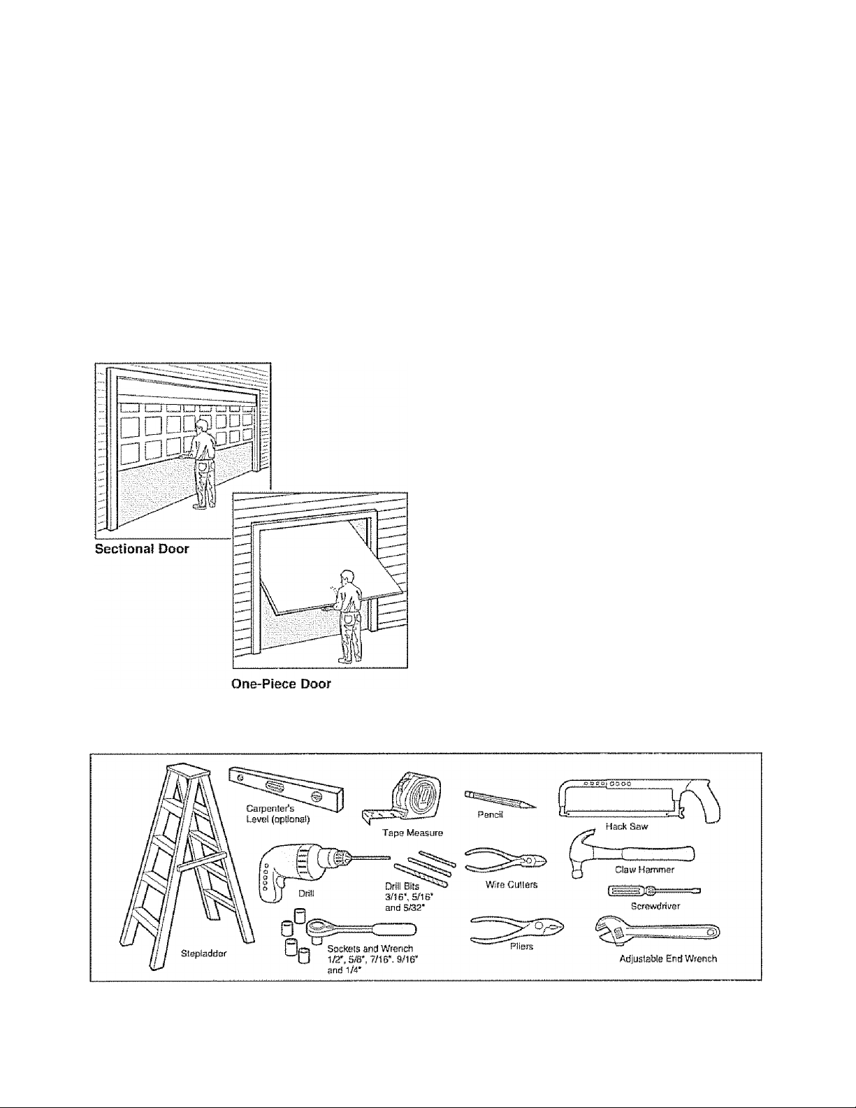
PFeparmg your garage door
Before you begin:
• Disable iocks.
• Remove any ropes connected to garage door,
• Complete the following test to make sure your
garage door is baianced and is not sticking or
binding:
1 Lift the door about halfway as shown. Release
the door. If balanced, it should stay in place,
supported entirely by its springs.,
2, Raise and iower the door to see if there is any
binding or sticking
If your door binds, sticks, or is out of balance, call a
trained door systems technician
A WARNING
To preveni posabls SERIOUS INJURY or DEATH:
• ALWAYS cal! a trained door systems technician if
garage door binds, sticks, or is out of balance. An
unbalanced garage door may not reverse when
required,
• NEVER try to loosen, move or adjust garage door, door
springs, cables, pulleys, brackets or their hardware, all
of which are under ECTREME tension
• Disable ALL locks and remove ALL ropes connected to
garage door BEFORE installing and operating garage
door opener to avoid entarigiement
CAUTION
To prevent damage to garage door and opener:
• ALWAYS disable locks BEFORE installing and operating
the opener,
• ONLY operate garage door opener at 120V, 60 Hz to
avoid malfunction and damage
Tools needed
During assembly, instaliation and adjustment of the
opener, instructions wili calf for hand tools as
iliustrated below.
Plamumg
Identify the type and height of your garage door.
Survey your garage area to see if any of the
conditions below apply to your installation. Additiona!
materials may be required. You may find it helpful to
refer back to this page and the accompanying
iliustrations as you proceed with the instaliation of
your opener.
Depending on your requirements, there are several
instaliation steps which may call for materials or
hardware rtot included in the carton
• Installation Step 1 Look at the wall or ceiling
above the garage door, The header bracket must
be securely fastened to structural supports,
« Installation Step 5 - Do you have a finished ceiling
in your garage? If so, a support bracket and
additionai fastening hardware may be required.
• Installation Step 10 ~ Depending upon garage
construction, extension brackets or wood blocks
may be needed to install sensors.
• Instaliation Step 10 - Alternate floor mounting of
the safety reversing sensor will require hardware
not provided..
Do you have an access door in addition to the
garage door? If not, Model 53702 Emergency Key
Rpipqcro ic rpniiirpri Rp-p Arr*pciisnriPR nSHP
Look at the garage door where it meets the floor.
Any gap between the floor and the bottom of the
door must not exceed 1/4“ (6 mm). Otherwise, the
safety reversal system may not work properly. See
Adjustment Step 3„ Floor or door should be
repaired.
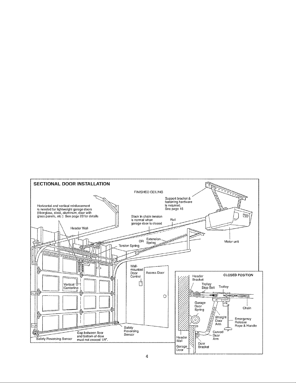
SECTIONAL DOOR INSTALLATIONS
• Do you have a steel, aluminum, fiberglass or glass
panel door? If so, horizontal and vertical
reinforcement is required (Installation Step 11).
• The opener should be installed above the center of
the door If there Is a torsion spring or center
bearing plate in the way of the header bracket, if
may be installed within 4 feet (1 „22 m) to the left or
right of the door center. See Installation Steps 1
and 11.
• If your door is more than 7 feet (2.13 m) high, see
rail extension kits listed on Accessories page
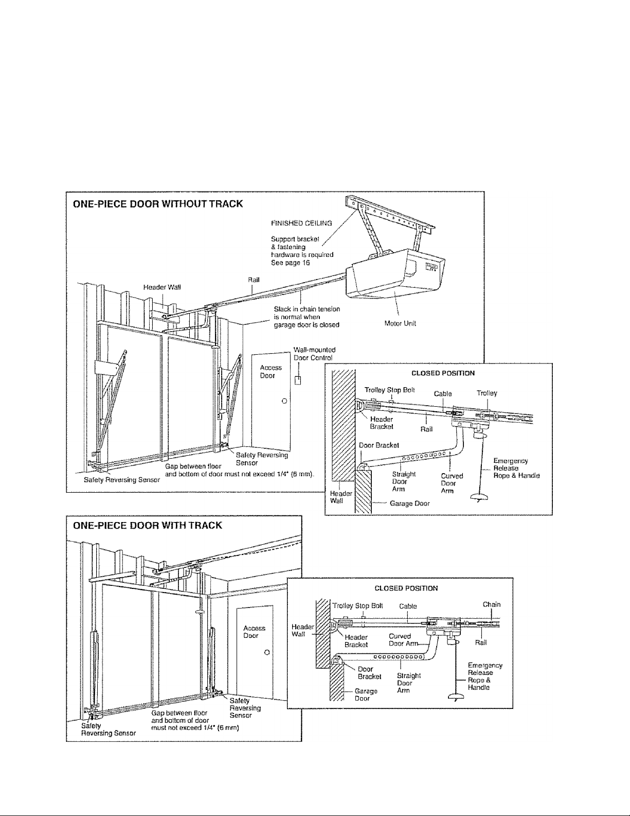
Planning fContinued)
ONE-PIECE DOOR INSTALLATIONS
• Generally, a one-piece door does not require
reinforcement. If your door is iightweight, refer (o
the information relating to sectional doors in
installation Step 11.
• Depending on your door's construction, you may
need additional mounting hardware for the door
bracket (Step 11).
AWARNING
Without a properly working safety reversal system,
persons (particularly small children) could be
SERIOUSLY INJURED or KILLED by a closing garage
door.
• The gap between the bottom of the garage door and
the floor MUST NOT exceed 1/4" (8 mm) Otherwise,
the safety reversal system may not work properly.
• The floor or the garage door MUST be repaired to
etimioate the gap
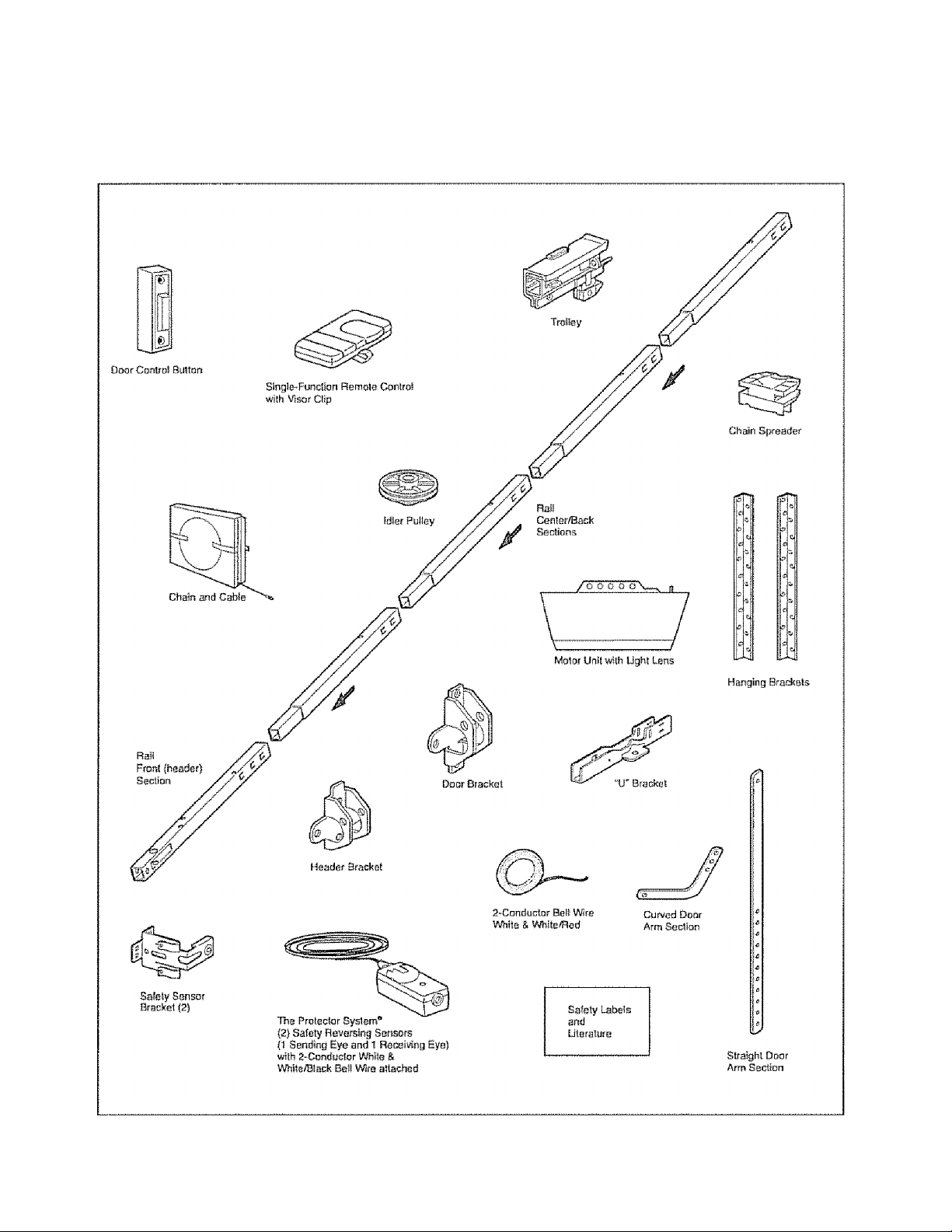
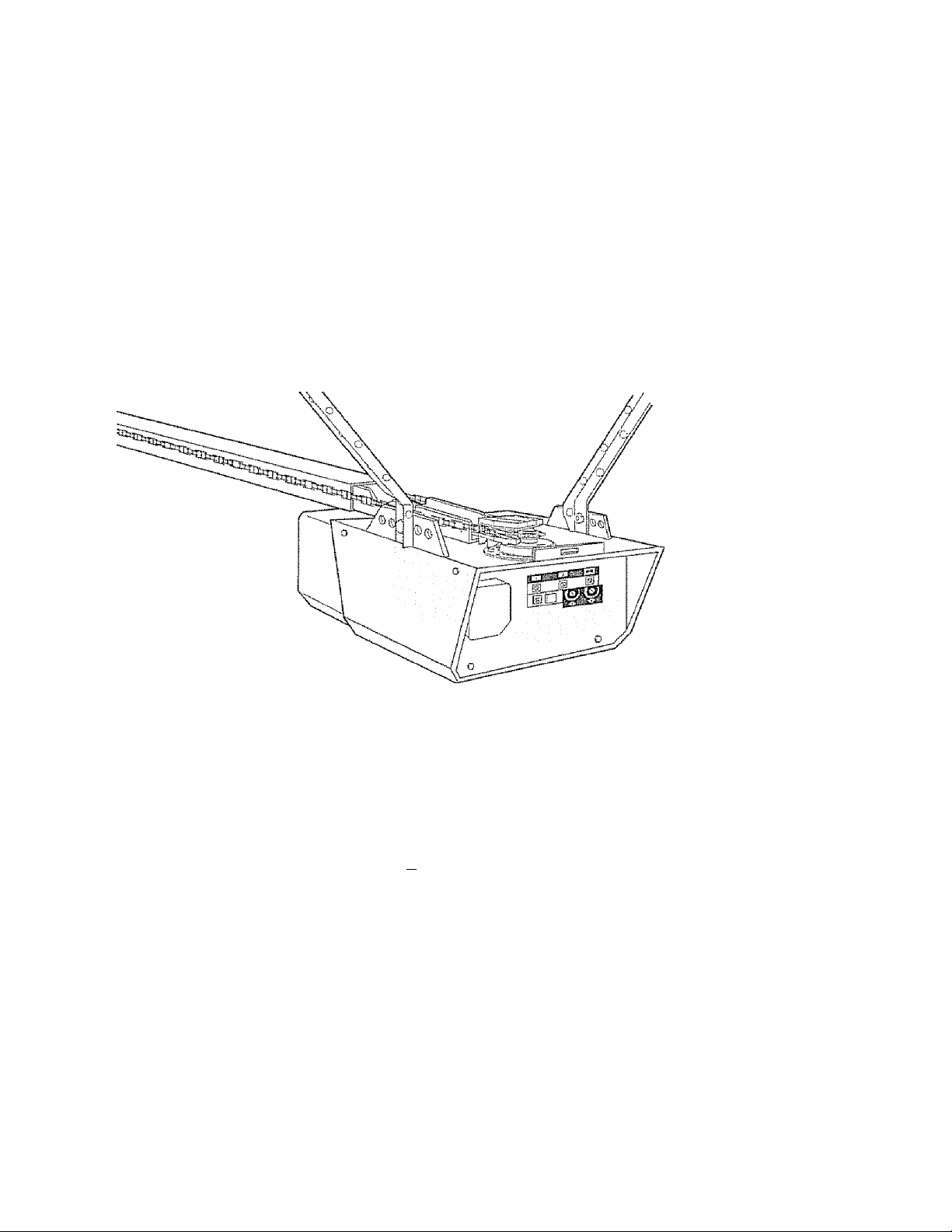
Carfoii Inwentory
Your garage door opener is packaged in one carton
which contains the motor unit and ali parts iliustrafoci
below.. Accessories will depend on the model
purchased. If anything is missing, carefully check the
packing material. Parts may be stuck in the foam,.
Hardware for assembly and instaiiation is shown on
the next page. Save the carton and packing material
until installation and adjustment is complete.
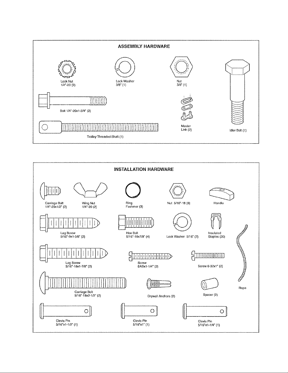
Hardware inventory
Separate all hardware and group as shown below for the assembly and inslaliation procedures.
ASSEMBLY STE^ 1
ñssemtie the Mali & Install the Hioftey
To avoid Installation difficulties, do not run the
garage door opener until instructed to do so.
CAUTIQM
To prevent iWJURY from pinching, keep hands and
fingers away from the joints while assembling the rail
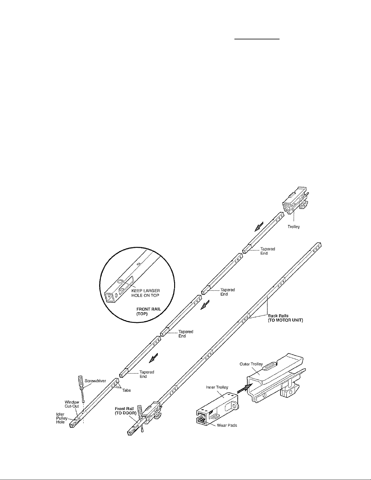
The frortt rail has a cut out ’’window” at the door end
(see illustration). The hah above this window is
larger on the top of the rail than on the bottom. A
smaller hole 3-1/2" (8.9 cm) away Is close to the rail
edge. Rotate the back rail so it has a similar hole
close to the opposite edge, about 4-3/4" (12 cm)
from the far end.
1 Remove the straight door arm and hanging
bracket packaged inside the front rail and set
aside for Installation Step 5 and 12. NOTE: To
prevent INJURY while unpacking the rail carefully
remove the straight door arm stared within the rail
section.
2. Aiign the rail sections on a flat surface as shown
and slide the tapered ends into the larger ones.
Tabs along the side will lock into place.
3. Place the motor unit on packing material to protect
the cover, and rest the back end of the rail on lop.
For convenience, put a support under the front
end of the rail
4. As a temporary trolley stop, insert a screwdriver
into the hole 10" (25 cm) away from the front of
the rail, as shown.
5. Check to be sure there are 4 plastic wear pads
inside the inner trolley, if they became loose
during shipping, check all packing material. Snap
them back into position as shown.
6. Slide the trolley assembly along the rail from the
back end to the screwdriver.
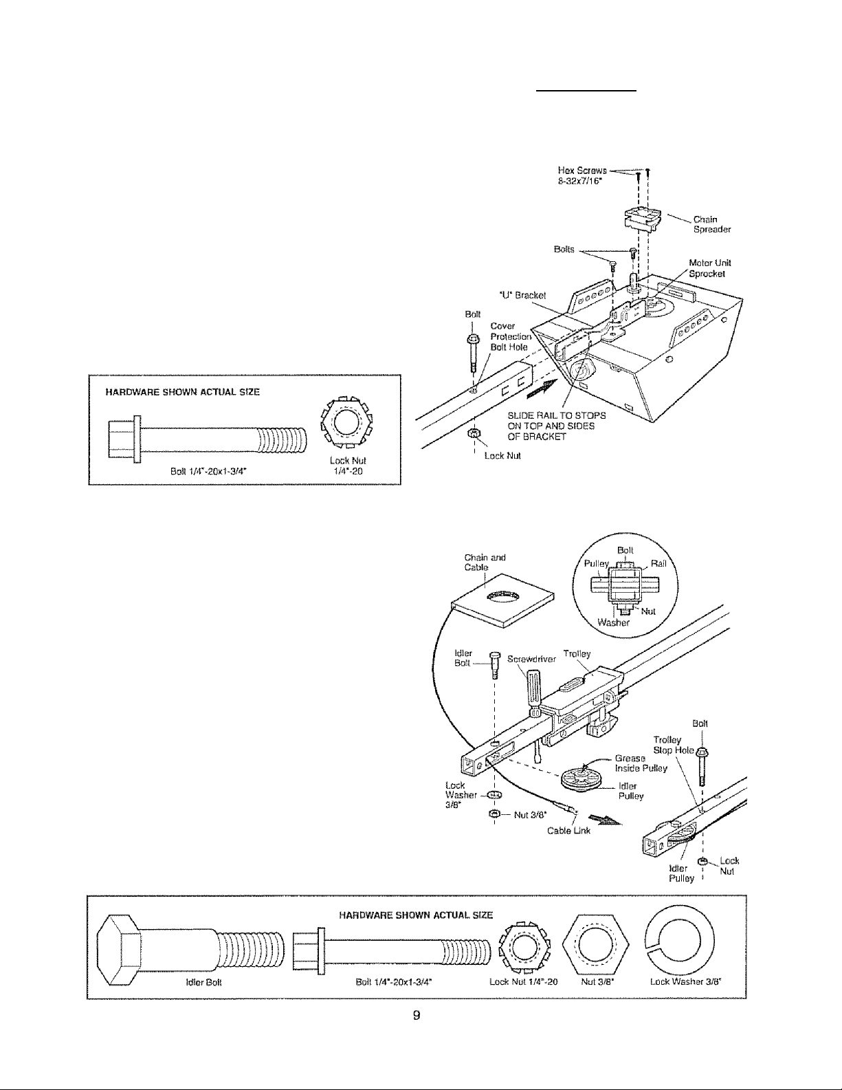
ASSEMBLY STEP 2
Fasten the Flail to the Motof Unit
• Insert a 1/4”-20x1-3/4 bolt Into the cover protection
bolt hole on the back end of the rail as shown.
Tighten securely with a 1/4"~20 lock nut. Do NOT
overtighten.
• Remove the two bolts from the top of the motor
unii
• Place the “U" bracket, flat side down onto the
motor unit and align the bracket hole with the bolt
holes.. Fasten with the previously removed bolts
• Align the rail assembly with the top of the motor
unit.. Slide the rail end onto the “U" bracket, all the
way to the stops that protrude on the top and sides
of the bracket
• Attach spreader to the motor unit with two screws.
CAUTION
To avoid SERIOUS damage to garage door opener,
use ONLY those bolts/fasteners mounted in the top of
the opener.
ASSEMBLY STEP 3
Install the Idler Pulley
• Lay the chain/cable beside the rail, as shown.
Grasp the end of the cable and pass
approximately 12” (30 cm) of cable through the
window. Allow it to hang until Assembly Step 5,
• Remove the tape from the idler pulley The inside
center should be pre-greased, If dry, regrease to
ensure proper operation.
• Place the Idler pulley into the window as shown.
• Insert the idler bolt from the top through the rail
and pulley. Tighten with a 3/8" lock washer and nut
underneath the rail until the lock washer is
compressed.
• Rotate the pulley to be sure it spins freely
• Insert a 1/4"~20x1'3/4 bolt into the trolley stop hole
in the front of the rail as shown Tighten securely
with a 1/4“-20 lock nut.
ASSEMBLY STEP 4
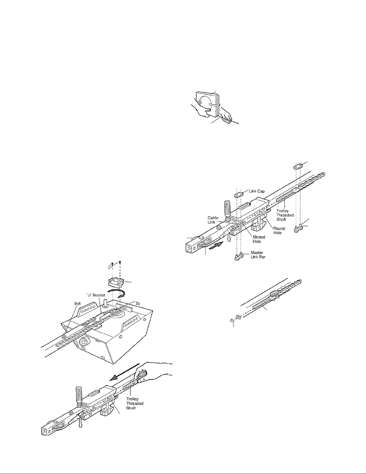
tosfall the Cham/C&ble
1, Puli the cable around the idler pulley and toward the
trotley.
2 Connect the cable to the retaining slot on the trolley,
as shown (Figure 1):
• From below, push pfns of master link bar up
through cable link and trolley slot.
• Push master link cap over pins and past pin
notches,
• Slide clip-on spring over cap and onto pin notches
until both pins are securely locked in place.
3. With the trolley against the screwdriver, dispense
the remainder of the cable/chatn along the rail
toward the motor unit into the slot on the chain
spreader, around the sprocket onto the chain
spreader artd continuing to the trolley assembly.
The sprocket teeth must engage the chain
(Figure 2).
4. Check to make sure the chain is not twisted, then
connect it to the threaded shaft with the remaining
master link.
5. Thread the inner nut and took washer onto the
trolley threaded shaft (Figure 3) .
6. Insert the trolley threaded shaft through the hole in
the trolley Be sure the chain is not twisted
(Figure 4).
7. Loosely thread the outer nut onto the trolley
threaded shaft.
8. Remove the screwdriver
A WARNING
To avoid possible SERIOUS INJURY to fingers from
moving garage door opener:
• ALWAYS keep hand clear of sprocket while operating
opener.
• Securely attach chain spreader BEFORE operating.
Dispensing Carten
Leave Chain and Cabte
Inside Dispensing
Carton to Prevent KInWng
Keep Chain and Cabía
Taut When Dispensing
Figure 1
Master Llnk_
Ciip'Qn Spring—r-T Master
Master Link
Clip-On Springer Master
Idiw
Puitey
Cable
_
Uni! Cap
Pin
Natch
Master
Liiik Bar
Figure 2 Hex Screws/
8*32x7/1
Figure 4
Round
Hale
Chain
Spreader
Motor Unit
!OCkal
10
Figure 3
^ Inner Nut
LocN S/16"
Washer
S/16*
Troitay
Ttifeaded
Shalt
ASSEMBLY STEP 5
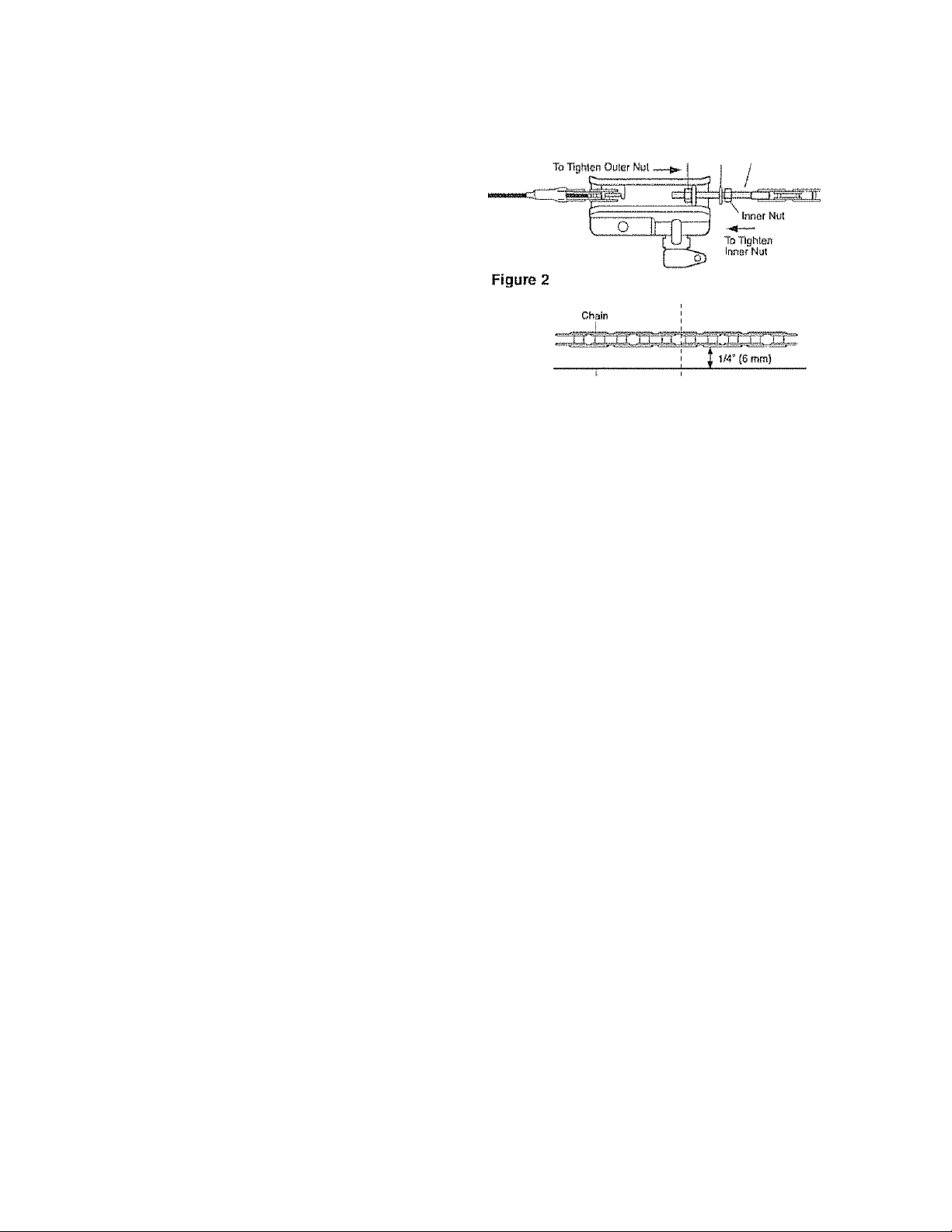
Tighten the Chain
• Spin the inner nut and lock washer down the
trolley threaded shaft, away from the trolley.
• To tighten the chain, turn outer nut in the direction
shown (Figure 1),
• When the chain is approximately 1/4” (6 mm)
above the base of the rail at its midpoint, re-tighten
the inner nut to secure the adjustment-
Sprocket noise can result if chain is too loose.
When installation is complete, you may notice some
chain droop with the door dosed This is normal, If
the chain returns to the position shown in Figure 2
when the door is open, do not re-adJust the chain
NOTE: During future maintenance, ALWAYS pull the
emergency release handle to disconnect trolley
before adjusting chain. You may notice loosening of
chain after Adjustment Step 3 (Test the Safety
Reversal System) Check for proper tension and
readjust chain if necessary. Then repeat Adjustment
Step 3.
You have now finished assembling your garage
door opener. Please read the following warnings
before proceeding to the installation section.
Figure 1
Bijse o! Bail
Oiitof Lock Thread od
Nut Wustier Shaft
Mid length ol Bail
Trolley
iMSTALLATiON
IMPORTANT INSTALLATION INSTRUCTIONS
A^WARNING
To reduce the risk of SEVERE INJURY or DEATH:
- READ AND FOLLOW ALL INSTALLATION WARNINGS
AND INSTRUCTIONS,,
. Install garage door opener only on properly balanced
and lubricated garage door An improperly balanced
door may not reverse when required and could result in
SEVERE INJURY or DEATH.
All repairs to cables, spring assemblies and other
hardware MUST be made by a trained door systems
tachnidan BEFORE installing opener.
Disable all locks artd remove all ropes connected to
garage door BEFORE installing opener to avoid
entanglement,,
Install garage door opener 7 feet (213 m) or mors
above floor.
Mount emergency release handle 6 feet (1 B3 m) above
floor
, NEVER connect garage door opener to power source
until instructed to do so.
8-, NEVER wear watches, rings or loose clothing while
instaH'mg or servicing opener. They could be caught in
garage door or opener mechanisms,
9 Install wall-mounted garage door control:
• within sight of the garage door.
• out of reach of children at minimum height of 5 feet
(1.5 m).,
• away from all moving parts of the door,
10. Place entrapment warning label on wall next to garage
door control
11. Place manual reiease/safety reverse test label in plain
view on inside of garage door
12. Upon completion of installation, test safety reversal
system. Door MUST reverse on contact with a
1-1/2" (3,8 cm) high object (or a 2x4 laid flat) on
the fioor
11
INSTALLATION STEP 1
Determine the Headier Bracket
Location
A WARNING
To prevent possible SERIOUS INJURY or DEATH:
• Header bracket MUST be RIGIDLY fastened to
structural support on header wall or ceiling, otherwise
garage door might riot reverse when required. DO NOT
install header bracket over drywatl.
• Concrete anchors MUST be used if mounting header
bracket or 2x4 into masonry.
» NEVER try to loosen, move or adjust garage door,
springs, cables, putleys, brackets, or their hardware,
ail of which are under EXTREME tension,
• ALWAYS cal! a trained door systems tschniclan if
garage door binds, sticks, or is out of balance An
unbalanced garage door might not reverse when
required -
Instalfation procedures vary according to garage door
types Foltow the instructions which apply to your
door
1 Close the door and mark the inside vertical
centerline of the garage door,
2, Extend the line onto the header wall above the
door.,
You can fasten the header bracket within 4 feet
(1,22 m) of the left or right of the door center
oniy if a torsion spring or center bearing plate
is in the way; or you can attach it to the ceiling
(see page 13) when clearance is minimal. (It
may be mounted on the wall upside down If
necessary, to gain approximately 1/2" (1 cm).)
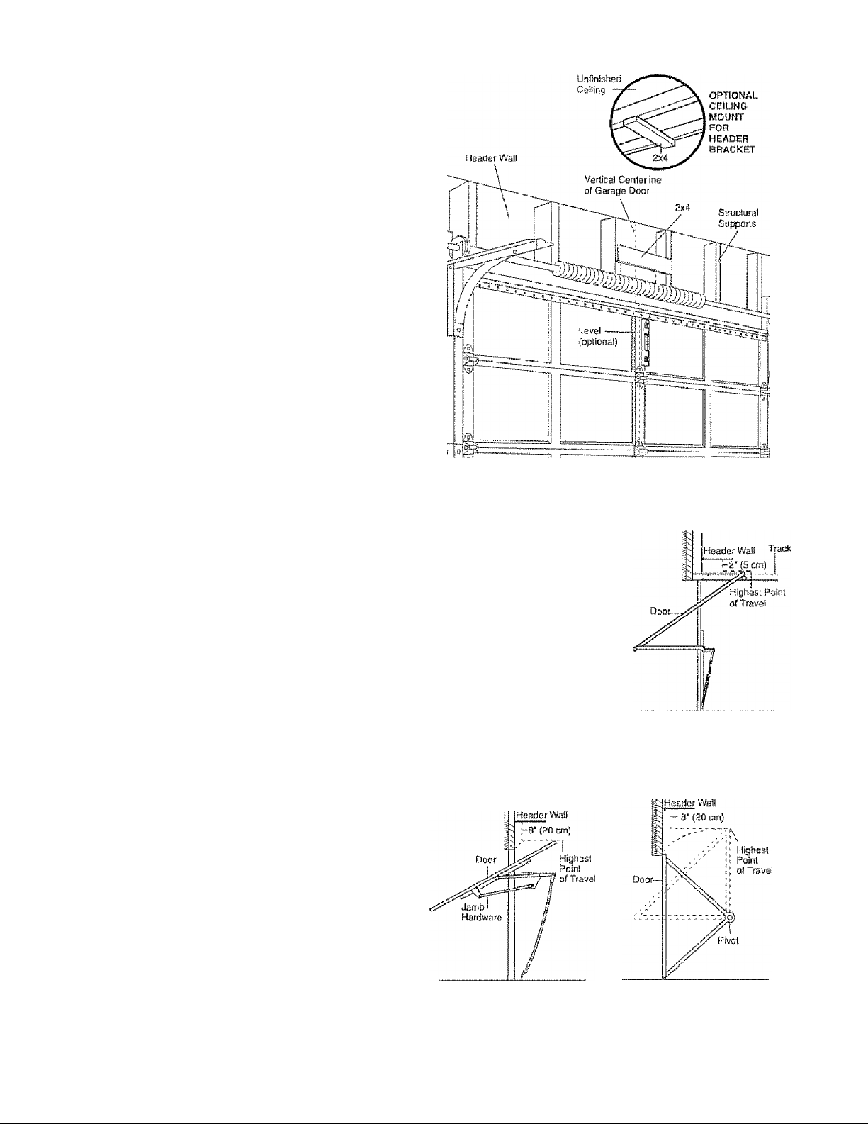
If you need to install the header bracket on a 2x4
(on wail or ceiling), use lag screws (not provided)
to securely fasten the 2x4 to structurai supports as
shown here and on page 13,
3, Open your door to the highest point of travei as
shown. Draw an intersecting horizontal line on the
header wall above the high point:
• 2" (5 cm) above the high point for sectional door
and one-piece door with track,
• 8" (20 cm) above the high point for one-piece
door without track.
This height will provide travel clearance for the top
edge of the door
NOTE: If the total number of inches exceeds the
height available in your garage, use the maximum
height possible, or refer to page 13 for ceiling
installation.
Header Wai
2" (S cm) Track
Highest Point
if rtig
of Travel
-Door
Sectional door wilii curved track
One-piece door with harizonlat track
One-piece door without track:
jamb hardware
12
One-piece door withoui track:
pivot hardware
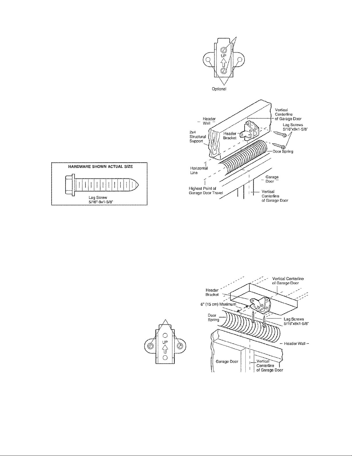
INSTALLATION STEP 2
Install the Header Bracket
You can attach the header bracket either to the wail
above the garage door, or to the ceiling. Follow the
instructions which will work best for your particular
requirements Do not install the header bracket
over drywail. ft installing into masortry, use
concrete anchors {not provided).
WALL HEADER BRACKET INSTALLATION
* Center the bracket on the vertical centerline with
the bottom edge of the bracket on the horizontal
line as shown (with the arrow pointing toward the
ceiting)
• Mark the veiticaf set of bracket holes,. Drill 3/16"
pilot holes and fasten the bracket securely to a
structural support with the hardware provided..
waw Mount
Mounting Hofes
CEILING HEADER BRACKET INSTALLATION
• Extend the vertical centerline onto the ceiling as
shown.
» Center the bracket on the vertical mark, no more
than 6" (15 cm) from the wall. Make sure the arrow
is pointing away from the wall. The bracket can be
mounted flush against the ceiling when clearance
is minima!,,
• Mark the side holes. Drill 3/16" pilot holes and
fasten bracket securely to a structural support with
the hardware provided.
Cefifng Mounting Holes
— Finishod Celtmg
13
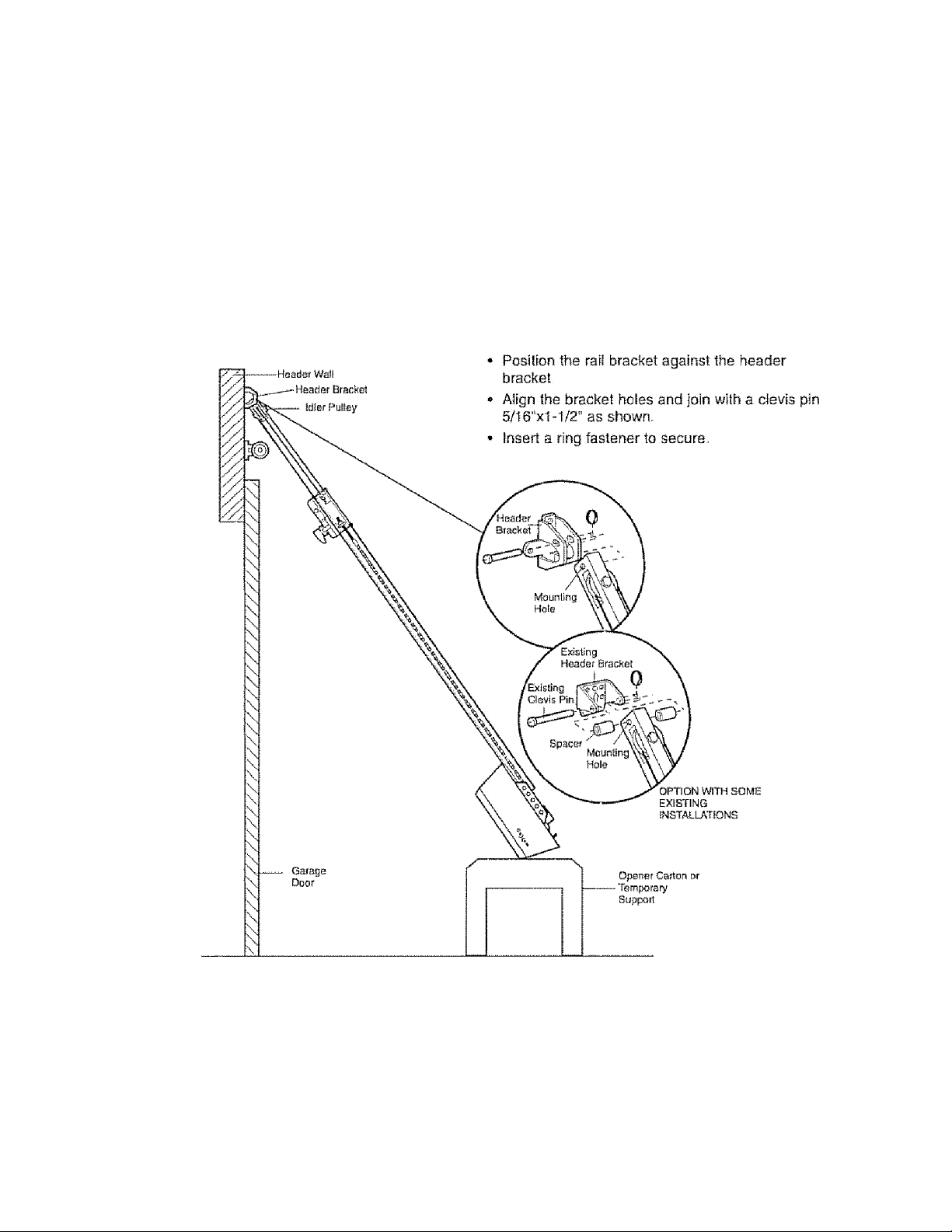
iNSTALLift.Tl©ii STEP 3
Attach the Rail to the Header
Bracket
NOTE: (Optional) With some existing installations,
you may re-use the old header bracket with the two
plastic spacers included in the hardware bag. Place
the spacers inside the bracket on each side of the
rail, as illustrated.
* Position the opener on the garage floor below the
header bracket Use packing material as a
protective base NOTE: If the door spring is in the
way you'll need help. Have someone hold the
opener securely on a temporary support to allow
the rail to clear the spring.
HARDWARE SHOWN ACTUAL S!ZE
HJ
Clevis Pin B/16' X I'le'
14
Oi
o
Ririfl fastener
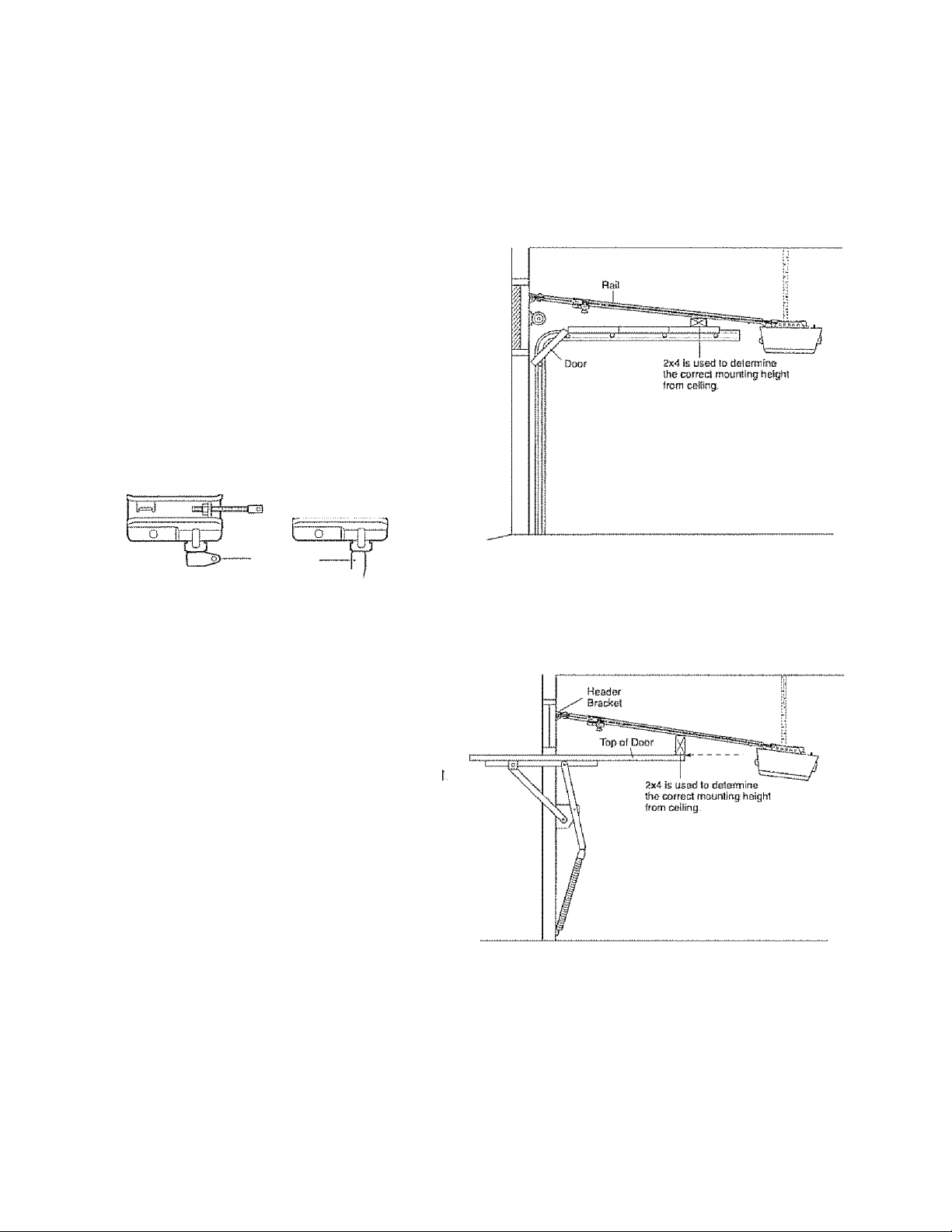
IMSmLLATiOfl STEP 4
Position the Opener
Follow instructions which apply to your door type as
iilustraled,
SECTIONAL DOOR OR ONE-PIECE DOOR WITH
TRACK
A 2x4 laid flat is convenient for setting an ideal
door-to-rall distance
• Remove foam packaging-
• Raise the opener onto a stepiadder You will need
help at this point if the ladder !s not tali enough.
• Open the door all the way and place a 2x4 laid flat
on the top section beneath the rail,
• И the top section or panel hits the trolley when you
raise the door, pul! down on the trolley release arm
to disconnect Inner and outer sections. Slide the
outer trolley toward the motor unit. The trolley can
remain disconnected until Installation Step 12
is completed.
CAUTION
To prevent damage to garage door, rest garage door
opener rail on 2x4 placed on top section of door.
Trolley
Release Arm
ENGAGED
RELEASED \cj
ONE-PIECE DOOR WITHOUTTRACK
A 2x4 on its side is convenient for setting an ideal
door-to-rail distance.
• Remove foam packaging
• Raise the opener onto a stepiadder. You will need
help a! this point if the ladder is not tall enough.
• Open the door all the way and place a 2x4 on its
side on the top section of the door beneath the rai
• The top of the door should be level with the top of
the motor unit Do not position the opener more
than 4“ (10 cm) above this point.
15

INSTALLATiON STEP S
Hang the Opener
Three representasive inslallalions are shown. Yours
may be different Hanging brackets should be angled
(Figure 1 ) to provide rigid support. On finished
ceilings (Figure 2 and Figure 3), attach a sturdy
metal bracket to structural supports before installing
the opener. This bracket and fastening hardware are
not provided.
1Measure the distance from each side of the motor
unit to the structural support.
2, -Cut both pieces of the hanging bracket to required
lengths,,
3, Drlli 3/16" pilot holes in the structural supports,
4, Attach one end of each bracket to a support with
S/16“-18x1-7/8" lag screws
5, Fasten the opener to the hanging brackets with
5/16""18x7/8“ hex bolts, lock washers and nuts,,
6, Check to make sure the rail is centered over the
door (or in iine with the header bracket if the
bracket is not centered above the door)
7, Remove the 2x4. Operate the door manually. If the
door hits the rail, raise the header bracket.
NOTE: DO NOT connect power to opener at
this time.-
Á WARNING
To avoid possible SERIOUS INJURY from a faKing
garage door opener, fasten it SECURELY to structural
supports of the garage. Concrete anchors MUST be used
if instaiiifig any brackets into masonry
Bo« s/íe"--fñx7/r
Lock Washer so 6*
Nu15/16'-ia
Figure 2
16
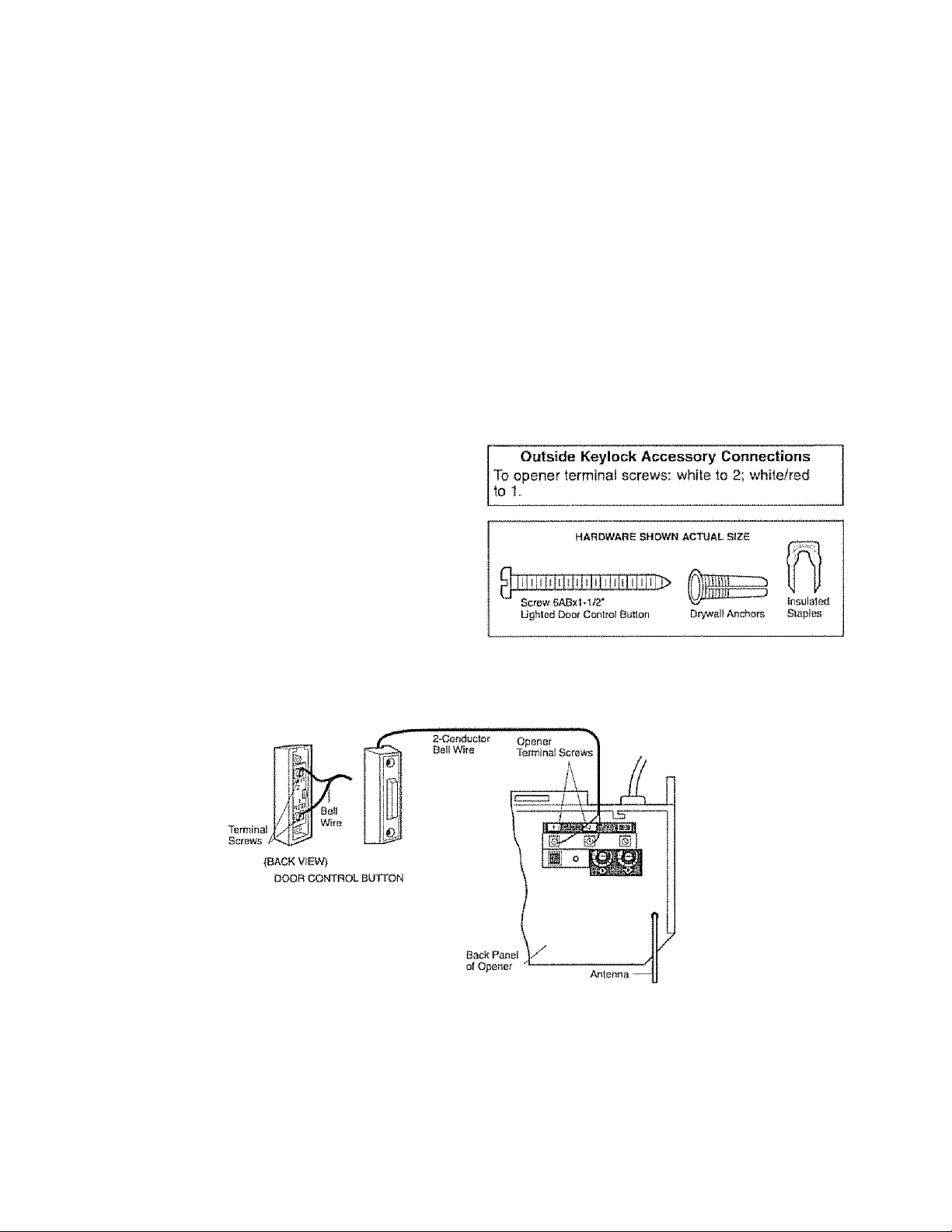
mSTilLLATICIIi STEP 6
tnstafl the Boor Control
Locate door control within sight of door, at a
minimum height of 5 feet (1.5 m) where small
children cannot reach, away from moving parts of
door and door hardware.
1 Strip 1/4" {6 mm) of insulation from one end of belt
wire and connect to the two terminal screws on
back of door control by color: white to 2 and
white/red to 1
2. Fasten the Door Control Button securely with
6ABx1-1/2" screws If installing into drywali, drill
6/32“ holes and use the anchors provided.
3. Run bell wire up wail artd across celling to motor
unit Use Insulated staples to secure wire in
several places. Do not pierce wire with a staple,
creating a short or open circuit.
4 Connect the bell wire to the terminal screws on the
motor unit panel; white to 2; white/red to t.
5. FostUon the antenna wire as shown.
6. Use tacks or staples to permanently attach
entrapment warning label to wail near door control,
and manual release/safety reverse test label in a
prominent location on inside of garage door.
NOTE: DO NOT connect power and operate opener
at this time. The trottey will travel to the full open
position but will not return to the close position until
the sensor beam is connected and property aligned.
A A WARNING
To prevent possible SERIOUS INJURY or DEATH from
electrocution;
• Be sure power is not connected BEFORE installing door
control
»Connect ONLY to 24 VOLT iow voltage wires.
To prevent possible SERIOUS iNJURY or DEATH from a
closing garage door;
• Install door cofilro! within sight Of garage door, out of
reach of children at a nninimum height of 5 feet
(1.5 m), and away from ail rnovifig parts of door
• NEVER permit children to operate or play with door
control push buttons or remote control transmitters,
• Activate door ONLY when it can be seen clearly, is
properly adjusted, and there are no obstructions to door
travel.
• ALWAYS keep garage door In sight until completely
closed, NEVER permit anyone to cross path of closing
garage door,
17
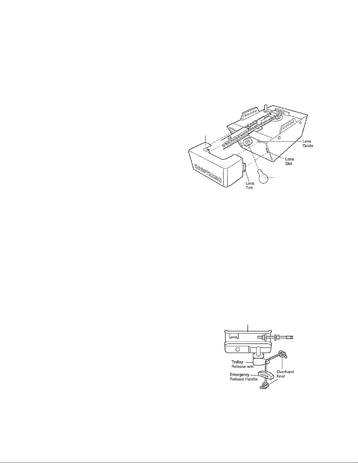
IMSmLLATiOl« STEP 7
install th& Light
• Instail a 75 watt maximum light bulb in the socketLight bulb size shoutd be A19, standard neck only.
The light will turn ON and remain lit for
approximately 4-1/2 minutes when power is
connected, Then the light will turn OFF.
• Apply slight pressure on the sides of the lens and
slide the tabs into the slots in the end panel (See
(liustraiion),
• To remove, reverse the procedure. Use care to
avoid snapping off lens tabs.
• Use At 9, standard neck garage door opener bulbs
for replacement.
NOTE: Use only a standard light bulb. The use of a
short neck or speciality light bulb may overheat the
endpanel or light socket.
CAUTiON
To prevent possible OVERHEATING of the endpanel or
light socket:
• DO NOT use short neck or specialty light buibs.
• DO NOT USB halogen bulbs. Use ONLY incandescent
To prevent damage to the opener:
• DO NOT use bulbs larger than 75W.
• ONLY use A19 size bulbs.
light
Lens
7fi Wall (Max)
Sfancfard
Light Butb
INSTÂLLÂTÏ@N STEP 8
Attach the Emergency Release
Rope and Handle
* Thread one end of the rope through the hoie in the
top of the red handle so “NOTICE” reads right side
up as shown. Secure with an overhand knot at
least 1“ (2.5 cm) from the end of the rope to
prevent siipping.
* Thread the other end of the rope through the hole
in the release arm of the outer trolley
* Adjust rope length so the handle is 6 feet (1.83 m)
above the floor. Ensure that the rope and handle
clear the tops of all vehicles to avoid
entanglement. Secure with an overhand knot.
NOTE: If it is necessary to cut the rope, heat seal
the cut end with a match or lighter to prevent
unraveling.
A WARNING
To prEvent possible SERIOUS INJURV or DEATH from a
failing garage door:
• If possible, US6 emergency release handte to disengage
trolley ONLY when garage door is CLOSED Weak or
broken springs or unbalanced door could result in an
open door failing rapidly and/or unexpectedly
• NEVER use emergency release handle unless garage
doorway is clear of persons and obstructions
• NEVER use handle to pull door open or closed If rope
knot becomes untied, you could tali.
Tmllsy
18
INSTALLATiOM STEP 9
ESectFical S&qmr&ments
To avoid instaliation difficulties, do not run the
opener at this time.
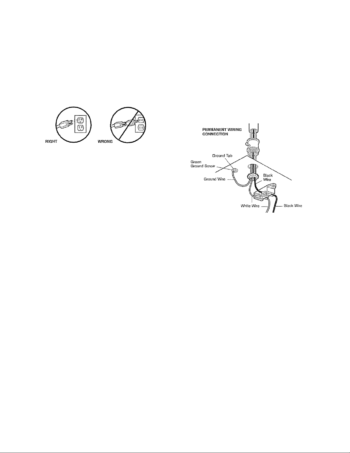
To reduce the risk of electric shock, your garage door
opener has a grounding type plug with a third
grounding pin. This plug will only fit into a grounding
type outlet- if the plug doesn't fit Into the outlet you
have, contact a qualified electrician to install the
proper outlet
If permanent wiring is required by your local
code, refer to the following procedure.
To make a permanent connection through the 7/8"
hole in the lop of the motor unit:
• Remove the motor unit cover screws and set the
cover aside,
• Remove the attached 3-prong cord.
• Connect the black (line) wire to the screw on the
brass terminal; the white (neutral) wire to the
screw on the silver terminal; and the ground wire
to the green ground screw, The opener must be
grounded,
• Reinstall the cover,
To avoid installation difficulties, do not run the
opener at this time.
WARNING
To prevent possible SERIOUS IfyjURY or DEATH from
electrocution or fire:
• Be sure power is not connected to the opener, and
disconnect power to circuit BEFORE removing cover to
establish permanent wiring connection
» Garage door installation and wiring MUST be in
compliance with all iocal sleetrical and building codes.
• NEVER use an eiitension cord, 2*wire adapter, or
change plug in arry way to make it fit outlet. Be sure
the opener is grounded.
19
INSTALLATIOM STEP 10
install The Protector System^
The safety reversing sensor must be connected
and aligned correctly before the garage door
opener will move in the down direction.
liyjPOBTANT INFORMATION ABOUT THE SAFETY
REVERSING SENSOR
When properly connected and aligned, the sensor
will delect an obsiacfe in the path of its electronic
beam.. The sending eye (with an amber indicator
light) transmits an invisible light beam to the
receiving eye (with a green indicator light).. If an
obstruction breaks the light beam while the door is
dosing, the door will stop and reverse to full open
position, and the opener lights will flash 10 times..
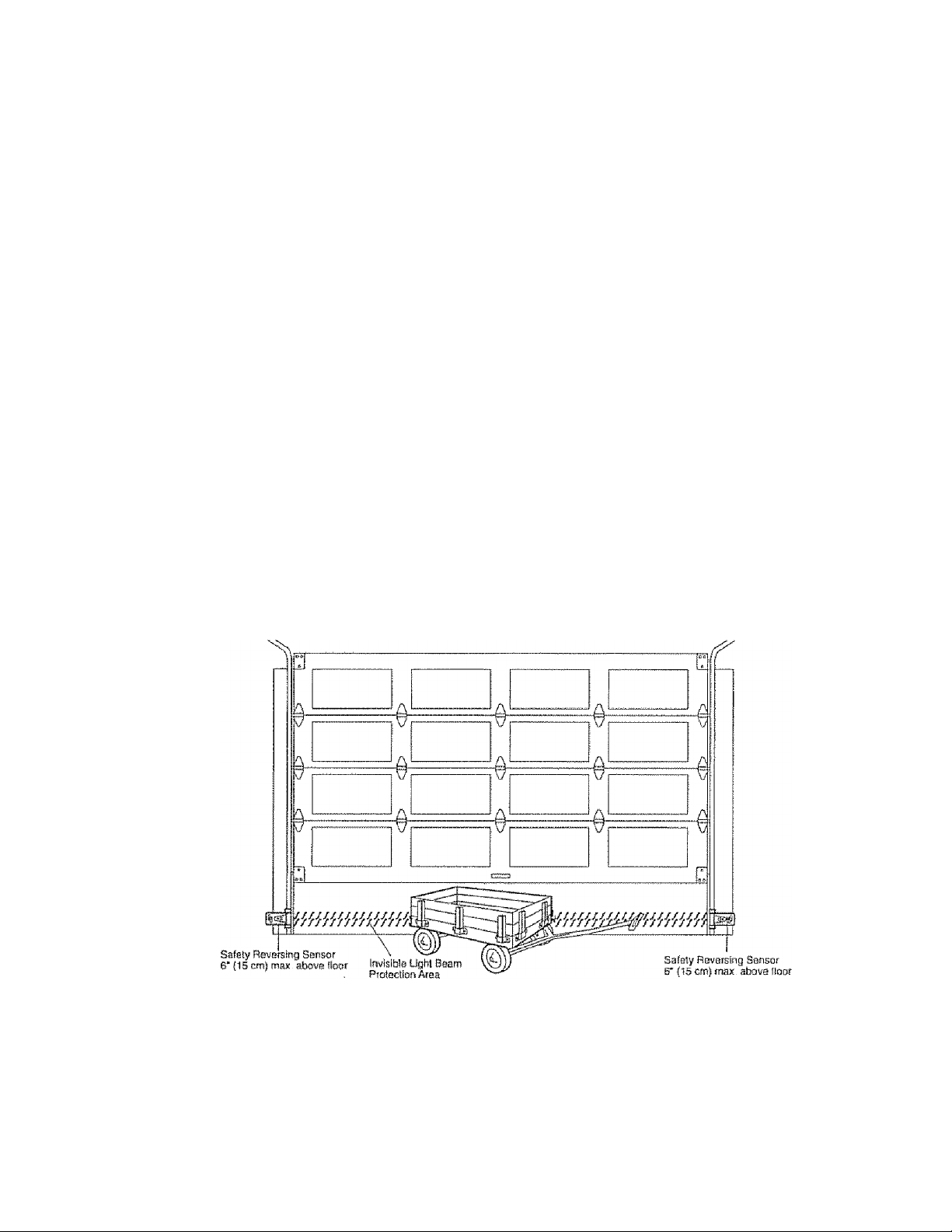
The units must be Installed inside the garage so that
the sending and receiving eyes face each other
across the door, no more than 6” (15 cm) above the
floor Either can be installed on the left or right of the
door as long as the sun never shines directly into the
receiving eye iens..
The mounting brackets are designed to clip onto the
track of sectional garage doors without additional
hardware
A WARNING
Be sure power is not connected to the garage door
opener BEFORE Installing the safety reversing sensor.
To prevent SERIOUS INJURY or DEATH from a closing
garage door:
• Correctly connect and align the safety reversing
sensor This required safety device MUST NOT be
disabled
• Install ttie safety reversing sensor so beam is NO
HIGHER than 6" (15 cm) above garage floor.
If It is necessary to mount the units on the wall, the
brackets must be securely fastened to a solid
surface such as the wall framing,. Extension brackets
(see accessories) are available if needed if
installing in masonry construction, add a piece of
wood at each location to avoid drilling extra holes in
masonry if repositioning is necessary.
The invisible light beam path must be unobstructed.
No part of the garage door (or door tracks, springs,
hinges, rollers or other hardware) may interrupt the
beam while the door is closing,.
Facing the door from inside the garage
20
INSTALLING THE BRACKETS
Be sure power to the opener is disconnected.
Install and align the brackets so the sensors will face
each other across the garage door, with the beam no
higher than 6“ (15 cm) above the floor. They may be
installed in one of three ways, as follows.
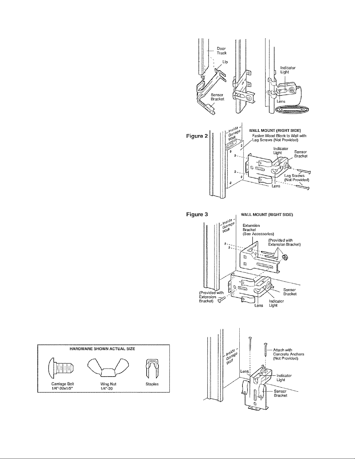
Garage door track installation (preferred):
• Slip the curved arms over the rounded edge of
each door track, with the curved arms facing the
door. Snap into place against the side of the track,
it should iie flush, with the lip hugging the back
edge of the track, as shown in Figure 1,
If your door track will not support the bracket
securely, wall instaiiation is recommended
Walt instaltation (Figure 2 & 3):
• Place the bracket against the wall with curved
arms facing the door Be sure there is enough
clearance for the sensor beam to be unobstructed.
» If additional depth Is needed, an extension bracket
(See Accessories) or wood blocks can be used
• Use bracket mounting holes as a template to
locate and drill (2) 3/16" diameter pilot holes on
the wall at each side of the door, no higher than
6" (15 cm) above the floor.
• Attach brackets to wail with lag screws
(Not provided),
• If using extension brackets or wood blocks, adjust
right and left assemblies to the same distance out
from the mounting surface. Make sure all door
hardware obstructions are cleared.
Floor installation (Figure 4):
• Use wood blocks or extension brackets (See
Accessories) to elevate sensor brackets so the
lenses will be no higher than 6” (15 cm) above the
floor.
• Carefully measure and place right and left
assemblies at the same distance out from the wail.
Be sure all door hardware obstructions are
cleared,
• Fasten to the floor with concrete anchors as
shown,.
Figure 1
DOOR TRACK MDUMT (RIGHT SIDE)
21
Figure 4
floor mount (RIGHT SIDE)
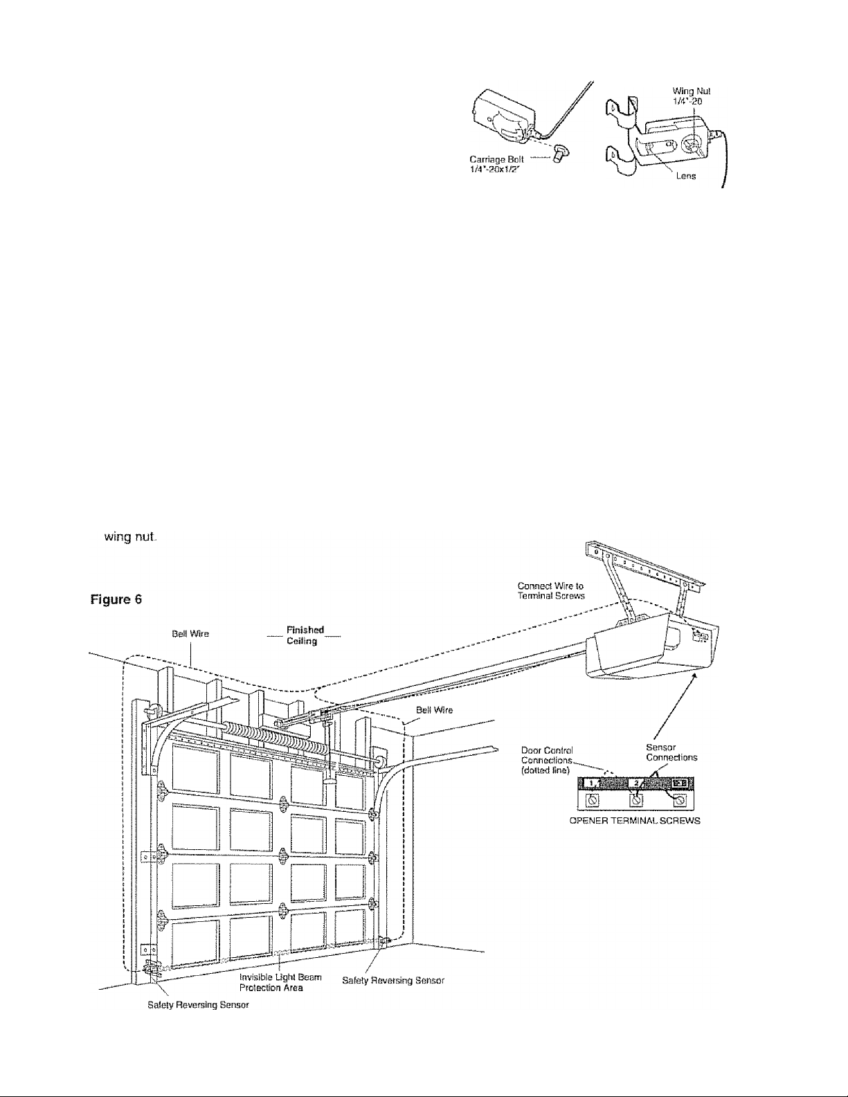
MOUNTING AND WIRING THE SAFETY
REVERSING SENSORS
• Slide a 1/4“*20x1/2” carriage bolt head into the slot
on each sensor Use wing nuts to fasten sensors to
brackets, with ienses pointing toward each other
across the door Be sure the lens is not obstructed
by a bracket extension (Figure 5)
• Finger tighten the wing nuts.
• Run the wires from both sensors to the opener Use
insulated staples to secure wire to wail and ceiling.
• Strip 1/4" (6 mm) of insulation from each set of
wires. Separate white and white/black wires
sufficiently to connect to the terminal screws; white
to 2 and white/black to 3 (Figure 6).
ALIGNING THE SAFETY REVERSING SENSORS
• Plug in the opener. The indicator lights In both the
sending and receiving eyes will glow steadily if
wiring connections and alignment are correct
The sending eye amber indicator light will glow
regardless of alignment or obstruction. If the green
indicator light in the receiving eye is off, dim, or
flickering (and Ihe invisible light beam path is not
obstructed), alignment is required.
• Loosen the sending eye wing nut and readjust,
aiming directly at the receiving eye. Lock in place.
• Loosen the receiving eye wing nut and adjust
sensor until it receives the sender’s beam. When
the green indicator light glows steadily, tighten the
Figure 5
TROUBLESHOOTING THE SAFETY REVERSING
SENSORS
1. If the sending eye indicator tight does not glow
steadily ai\er inslaiiation, check for:
• Electric power to the opener.
• A short in the while or white/black wires, These
can occur at staples, or at opener connections.
« incorrect wiring between sensors and opener.
• A broken wire.
2 If the sending eye indicator light glows steadily but
the receiving eye indicator light doesn't:
• Check alignment
• Check for an open wire to the receiving eye.
3 , If the receiving eye indicator light is dim, reaiign
either sensor.
NOTE: When the invisible beam path is obstructed
or misaligned while the door is closing, the door will
reverse, lithe door is already open, it wHi not close.
The opener lights will blink 10 times. See page 20.
22
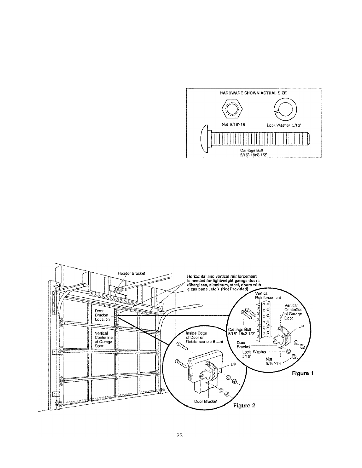
INSmLLATlON STEP 11
Pastsn the Door Bracket
Follow instruciions which apply to your door type
as illustrated below or on the following page.
A horizontal reinforcement brace should be long
enough to be secured to two vertical supports. A
vertical reinforcement brace should cover the
height of the top panel.
The illustration shows one piece of angle iron as the
horizontal brace. For the vertical brace, two pieces of
angle iron are used to create a U-shaped support
(Figure 1). The best solution is to check with your
garage door manufacturer lor an opener installation
door reinforcement kit.
NOTE: Mmy vertical brace hstallatlons provide for
direct attachment of the clevis pin and door arm.. In
this case you will not need the door bracket; proceed
to installation Step 12..
SECTIONAL DOORS
• Center the door bracket on the previously marked
vertical centerline used for the header bracket
installation. Note correct UP placement, as
stamped Inside the bracket (Figure 2) ,
• Position the bracket on the face of the door within
the following limits:
A) The top edge of the bracket 2”-4’' (5-10 cm)
below the fop edge of the door
8) The top edge of the bracket directly below any
structural support across the top of the door
CAUTION
Fiberglass, aluminum or lightweight steel garage doors
WILL REQUIRE reinforcement BEFORE installation of
door bracket Contact your door manufacturer for
reinforcement kit
* Mark and drill 5/16" left and right fastening holes..
Secure the bracket as shown in Figure 1 if there is
vertical reinforcement
If your installation doesn't require vertical
reinforcement but does need fop and bottom
fastening holes for the door bracket, fasten as shown
in Figure 2
 Loading...