

Craftsman 13953919 Owner’s Manual
Owner's Manual/Manual Del Propietario
II:RRFTSMRN+I
GARAGE DOOR OPENER
ABRIDOR DE PUERTA DE COCHERA
For Residential Use Only/Solo para uso residencial
Model/Modelo 139.53919
m
G3
Read and follow all safety rules
and operating instructions before
first use of this product.
Fasten the manual near the garage
door after installation.
Periodic checks of the opener are
required to ensure safe operation.
m
"13
Z_
O
Leer y seguir todas las reglas de
seguridad y las instrucciones de
operacion antes de usar este
producto por primera vez.
Guardar este manual cerca de la
puerta de la cochera.
Se deben realizar revisiones
periodicas del abridor de puertas
para asegurar su operacion
segura.
Sears, Roebuck and Co., Hoffman Estates, IL 60179 U.S.A
www.sears.com/craftsman
TABLE OF CONTENTS
Introduction 2- 7
Safety symbol and signal word review ........................ 2
Preparing your garage door ........................................ 3
Tools needed ............................................................... 3
Planning .................................................................. 4-5
Carton inventory .......................................................... 6
Hardware inventory ..................................................... 7
Assembly 8.11
Assemble the rail and install the trolley ...................... 8
Fasten the rail to the motor unit and
Install the idler pulley ................................................... 9
Install the belt and attach the belt cap retainer ......... 10
Set the tension .......................................................... 11
Installation 11-26
Installation safety instructions .................................... 11
Determine the header bracket location ..................... 12
Install the header bracket .......................................... 13
Attach the rail to the header bracket ......................... 14
Position the opener ................................................... 15
Hang the opener ....................................................... 16
Install the door control ............................................... 17
Install the lights ......................................................... 18
Attach the emergency release rope and handle ....... 18
Electrical requirements .............................................. 19
Install The Protector System ®.............................. 20-22
Fasten the door bracket ....................................... 23-24
Connect the door arm to the trolley ..................... 25-26
Adjustment 27-29
Program the travel limits ........................................... 27
Setting the force ........................................................ 28
Test the safety reversal system ................................. 29
Test The Protector System ®...................................... 29
Operation 30-36
Operation safety instructions ..................................... 30
Using your garage door opener ................................ 30
Using the wall-mounted Door Control ....................... 31
To open the door manually ........................................ 31
Battery backup unit .............................................. 32-33
Care of your garage door opener .............................. 34
Having a problem? .................................................... 35
Diagnostic chart ......................................................... 36
Programming 37-38
To add or reprogram a hand-held remote control .....37
To erase all codes ..................................................... 37
3-Function Remotes .................................................. 37
To add, reprogram or change
a Keyless Entry PIN .................................................. 38
Repair Parts 39-40
Rail assembly parts 39
Installation parts ........................................................ 39
Motor unit assembly parts ......................................... 40
Accessories 41
Warran ty 41
Repair Parts and Service 42
INTRODUCTION
Safety Symbol
and Signal Word Review
This garage door opener has been designed and tested to offer safe service provided it is installed, operated,
maintained and tested in strict accordance with the instructions and warnings contained in this manual.
When you see these Safety Symbols and Signal
Words on the following pages, they will alert you to
Mechanical
Electrical
the possibility of serious injury or death if you do
not comply with the warnings that accompany them.
The hazard may come from something mechanical
or from electric shock. Read the warnings carefully.
When you see this Signal Word on the following
pages, it will alert you to the possibility of damage to
your garage door and/or the garage door opener if
you do not comply with the cautionary statements
that accompany it. Read them carefully.
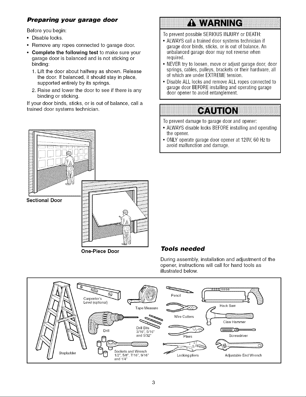
Preparing your garage door
Before you begin:
• Disable locks.
• Remove any ropes connected to garage door.
• Complete the following test to make sure your
garage door is balanced and is not sticking or
binding:
1. Lift the door about halfway as shown. Release
the door. If balanced, it should stay in place,
supported entirely by its springs.
2. Raise and lower the door to see if there is any
binding or sticking.
If your door binds, sticks, or is out of balance, call a
trained door systems technician.
To prevent possible SERIOUSINJURYor DEATH:
• ALWAYScall atrained door systems technician if
garage door binds, sticks, or is out of balance.An
unbalancedgarage door may not reverse when
required.
• NEVERtry to loosen,move or adjust garage door,door
springs, cables, pulleys, brackets ortheir hardware,all
of which are under EXTREMEtension.
• Disable ALL locks and removeALL ropes connected to
garage door BEFOREinstalling and operating garage
door opener to avoid entanglement.
To prevent damageto garage door and opener:
• ALWAYSdisable locks BEFOREinstalling and operating
the opener
• ONLYoperategaragedoor opener at 120V,60 Hzto
avoid malfunction and damage
Sectional Door
One-Piece Door
Level (optional)
Drill 3/16", 5/16"
Tools needed
During assembly, installation and adjustment of the
opener, instructions will call for hand tools as
illustrated below.
Pencil
Tape Measure
Dr_ Wire Cutters
and 5/32"
Hack Saw
Screwdriver
Stepladder
O0 S/°2c"_;t/_ 't n,11W!e;,il6" Locking pliers
and 1/4"
Adjustable End Wrench
Planning
Identify the type and height of your garage door.
Survey your garage area to see if any of the
conditions below apply to your installation. Additional
materials may be required. You may find it helpful to
refer back to this page and the accompanying
illustrations as you proceed with the installation of
your opener.
Depending on your requirements, there are several
installation steps which may call for materials or
hardware not included in the carton.
• Installation Step 1 - Look at the wall or ceiling
above the garage door. The header bracket must
be securely fastened to structural supports.
• Installation Step 5 - Do you have a finished ceiling
in your garage? If so, a support bracket and
additional fastening hardware may be required.
• Installation Step 10- Depending upon garage
construction, extension brackets or wood blocks
may be needed to install sensors.
• Installation Step 10 -Alternate floor mounting of
the safety reversing sensor will require hardware
not provided.
Do you have an access door in addition to the
garage door? If not, Model 53702 Emergency Key
Release is required. See Accessories page.
Look at the garage door where it meets the floor.
Any gap between the floor and the bottom of the
door must not exceed 1/4" (6 mm). Otherwise, the
safety reversal system may not work properly. See
Adjustment Step 3. Floor or door should be
repaired.
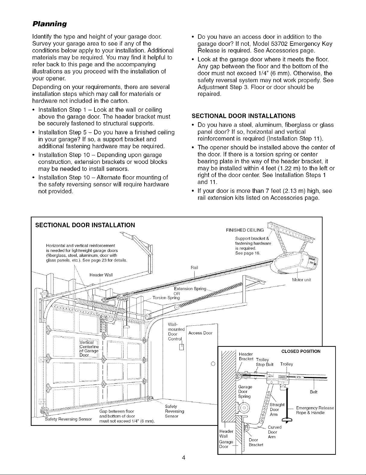
SECTIONAL DOOR INSTALLATIONS
• Do you have a steel, aluminum, fiberglass or glass
panel door? If so, horiFontal and vertical
reinforcement is required (Installation Step 11).
• The opener should be installed above the center of
the door. If there is a torsion spring or center
bearing plate in the way of the header bracket, it
may be installed within 4 feet (1.22 m) to the left or
right of the door center. See Installation Steps 1
and 11.
• If your door is more than 7 feet (2.13 m) high, see
rail extension kits listed on Accessories page.
SECTIONAL DOOR INSTALLATION
Horizontal and vertical reinforcement
is needed for lightweight garage doors
(fiberglass, steel, aluminum, door with
glass panels, etc.). See page 23 for details.
Header Wall
.................... ,Centerline_ertica[:i
....... @ooE _Jj
Gap between floor
Reversing Sensor must not exceed 1/4" (6 mm).
and bottom of door
.... Torsion Spring
Wall-
Door
Safety
Reversing
Sensor
Rail
Extension Spring
OR
[
FINISHED CEILING
O
eader
Iall
arage
3or -
Support bracket &
fastening hardware
is required.
See page 16.
Header
Bracket Trolley
Stop Bolt
Garage
Door
Spring
Door
Bracket
CLOSED POSlTION
Trolley
Curved
Door
Arm
Belt
Emergency Release
Rope & Handle
4
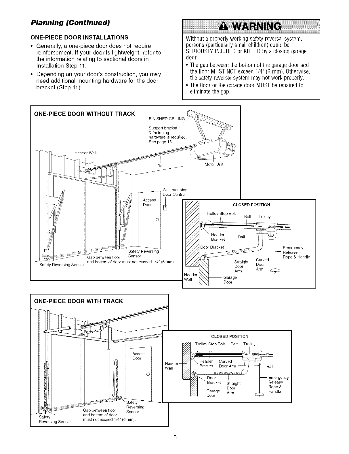
Planning (Continued)
ONE-PIECE DOOR INSTALLATIONS
• Generally, a one-piece door does not require
reinforcement. If your door is lightweight, refer to
the information relating to sectional doors in
Installation Step 11.
• Depending on your door's construction, you may
need additional mounting hardware for the door
bracket (Step 11).
ONE-PIECE DOOR WITHOUT TRACK
FINISHED CEILING
& fastening
hardware is required.
See page 16,
Header Wall
Without a properly working safety reversalsystem,
persons (particularly small children) could be
SERIOUSLYINJUREDor KILLEDby aclosing garage
door.
• Thegap betweenthe bottom of the garage door and
the floor MUSTNOTexceed 1/4"(6 mm). Otherwise,
the safety reversalsystem may not work properly.
• Thefloor or the garage door MUSTbe repairedto
eliminate the gap.
Motor Unit
CLOSED POSITION
Trolley Stop Bolt
Belt Trolley
i
AUtoti
Safety Reversing
Gap between floor Sensor
J* Safety Reversing Sensor and bottom of door must not exceed 1/4" (6 turn).
I ONE-PIECE DOOR WITH TRACK
let
Reversing
Saafety
Reversing Sensor
Gap between floor Sensor
and bottom of door
must not exceed 1/4" (6 ram),
Header
Wall
Header
Bracket
Door Bracket
4eader
Vail
Trolley Stop Bolt Belt Trolley
_'_-Head_r Curved
Bracket Door Arm _- /
Garage
Door
CLOSED POSiTiON
/_.,. oooooolooooo)_
Door I
Bracket Straight
_//A Door
Y//"A-- Garage Arm
_/I Door
Rail
Straight
Door
Arm
I
Curved
Door
Arm
-- Emergency
Release
Rope &
Handle
Emergency
Release
Rope & Handle
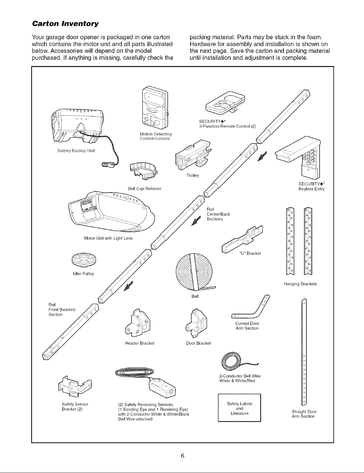
Carton Inventory
Your garage door opener is packaged in one carton
which contains the motor unit and all parts illustrated
below. Accessories will depend on the model
purchased. If anything is missing, carefully check the
Motion Detecting
Control Console
Belt Cap Retainer
packing material. Parts may be stuck in the foam.
Hardware for assembly and installation is shown on
the next page. Save the carton and packing material
until installation and adjustment is complete.
SECURITY÷ _
3-Function Remote Control (2)
Trolley
SECURITY,I#
Keyless Entry
Rail
Center/Back
Sections
Rail
Fron! (header) /_
y
Safety Sensor
Bracket (2)
Motor Unit with Light Lens
Idler Pulley
Header Bracket
(2) Safety Reversing Sensors
(1 Sending Eye and 1 Receiving Eye)
with 2-Conductor White & White/Black
Bell Wire attached
Belt
Door Bracket
Curved Door
Arm Section
2-Conductor Bell Wire
White & White/Red
Safety Labels
and
Literature
Hanging Brackets
Straight Door
Arm Section
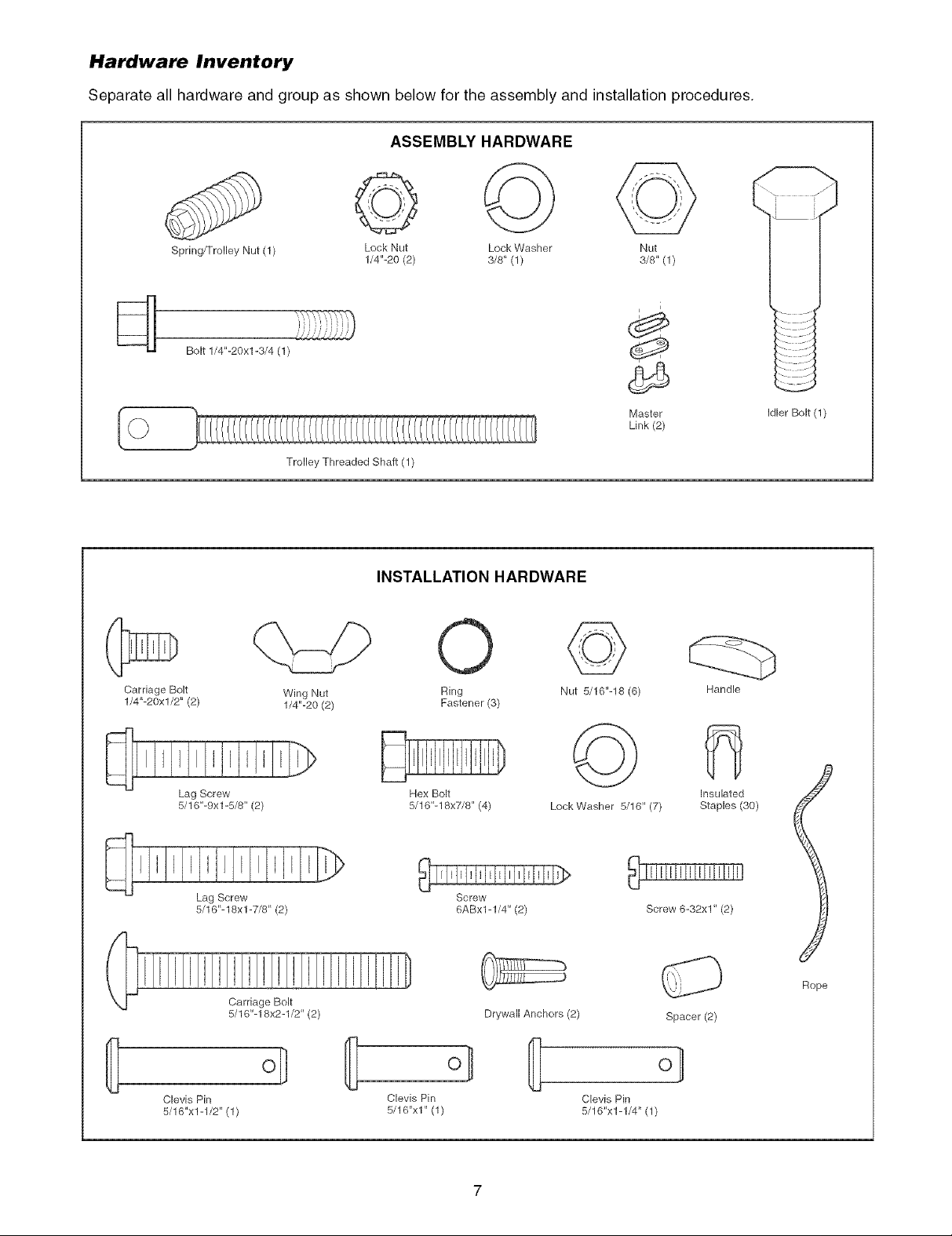
Hardware Inventory
Separate all hardware and group as shown below for the assembly and installation procedures.
ASSEMBLY HARDWARE
Spring/Trolley Nut (1)
Bolt 1/4"-20xl-3/4 (1)
Carriage Bolt
1/4"-20xl/2" (2)
Lock Nut Lock Washer Nut
1/4"-20 (2) 3/8" (1) 3/8" (1)
Trolley Threaded Shaft (1)
INSTALLATION HARDWARE
Wing Nut
1/4"-20 (2)
0
Ring
Fastener (3)
©
Nut 5/16"-18 (6)
i
d_
Master
Link (2)
Idler Bolt (1)
Handle
Lag Screw
5/16"-9xl -5/8" (2)
Lag Screw
5/16"-18xl -7/8" (2)
Clevis Pin
5/16"x1-1/2" (1)
Carriage Bolt
5/16"-18x2-1/2" (2)
o_
©
Hex Bolt
5/16"-18x7/8" (4)
Screw
6ABx1-1/4" (2)
Drywall Anchors (2)
Clevis Pin Clevis Pin
5/16"x1" (1) 5/16"x1-1/4" (1)
LockWasher 5/16" (7)
fi
Insulated
Staples (30)
Screw 6-32x1" (2)
Rope
Spacer (2)
o}
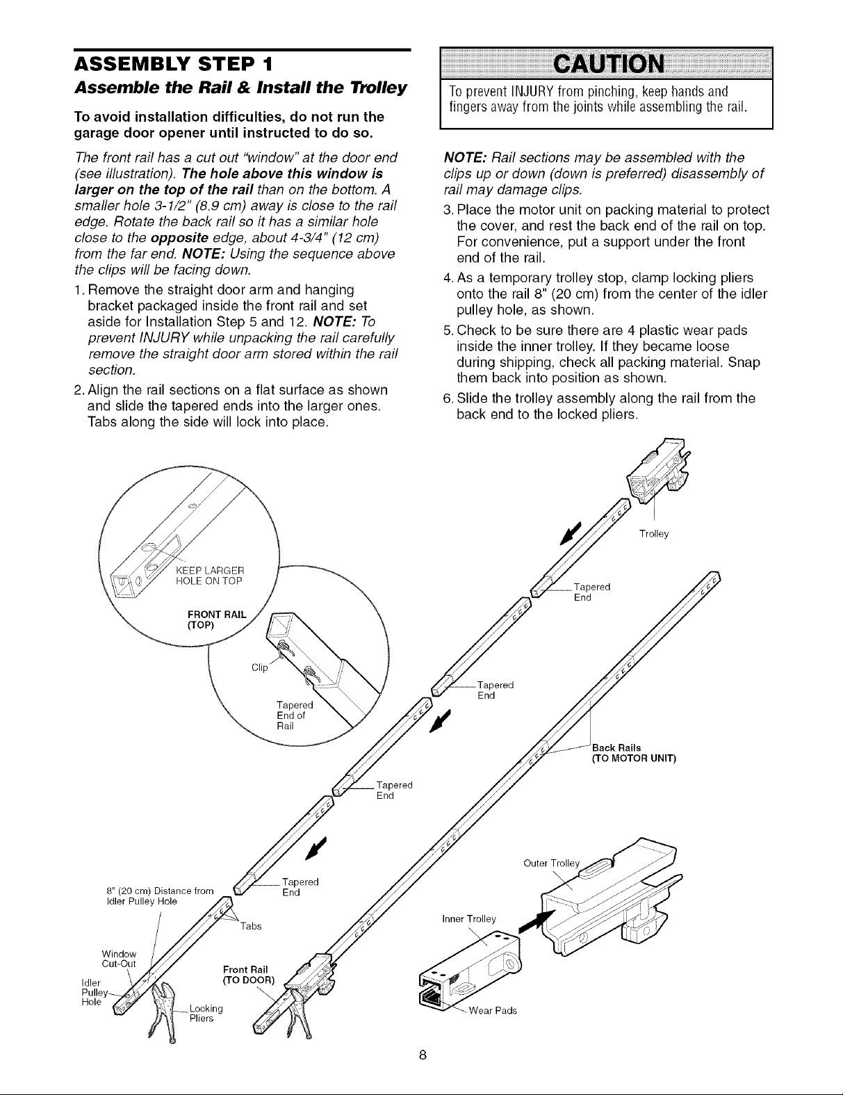
ASSEMBLY STEP 1
Assemble the Rail & Install the Trolley
To avoid installation difficulties, do not run the
garage door opener until instructed to do so.
The front rail has a cut out "window" at the door end
(see illustration). The hole above this window is
larger on the top of the rail than on the bottom. A
smaller hole 3-1/2" (8.9 cm) away is close to the rail
edge. Rotate the back rail so it has a similar hole
close to the opposite edge, about 4-3/4" (12 cm)
from the far end. NOTE: Using the sequence above
the clips will be facing down.
1. Remove the straight door arm and hanging
bracket packaged inside the front rail and set
aside for Installation Step 5 and 12. NOTE: To
prevent INJURY while unpacking the rail carefully
remove the straight door arm stored within the rail
section.
2. Align the rail sections on a flat surface as shown
and slide the tapered ends into the larger ones.
Tabs along the side will lock into place.
To prevent INJURYfrom pinching, keephandsand
fingers awayfrom the joints while assembling the rail.
NOTE: Rail sections may be assembled with the
clips up or down (down is preferred) disassembly of
rail may damage clips.
3. Place the motor unit on packing material to protect
the cover, and rest the back end of the rail on top.
For convenience, put a support under the front
end of the rail.
4. As a temporary trolley stop, clamp locking pliers
onto the rail 8" (20 cm) from the center of the idler
pulley hole, as shown.
5.Check to be sure there are 4 plastic wear pads
inside the inner trolley. If they became loose
during shipping, check all packing material. Snap
them back into position as shown.
6. Slide the trolley assembly along the rail from the
back end to the locked pliers.
8" (20 cm) Distance from
Idler Pulley Hole
Window
Cut-Out
Idler
Pulle
KEEP LARGER
HOLE ON TOP
FRONT RAIL
(TOP)
Front Rail
(TO DOOR)
__Locking
Pliers
Tabs
\
Tapered
End of
Rail
3ered
End
End
End
Inner Trolley
\
Wear Pads
Trolley
End
3ered
3ack Rails
(TO MOTOR UNIT)
Outer Trolley
\
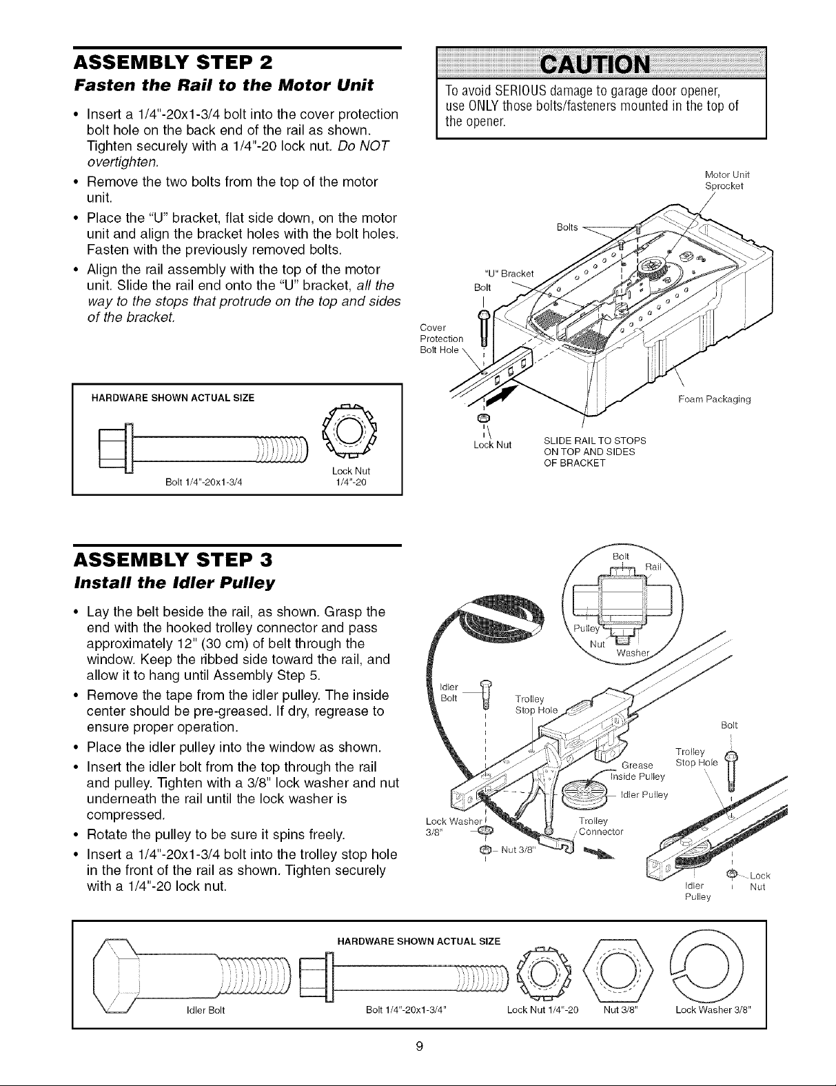
ASSEMBLY STEP 2
Fasten the Rail to the Motor Unit
• Insert a 1/4"-20xl-3/4 bolt into the cover protection
bolt hole on the back end of the rail as shown.
Tighten securely with a 1/4"-20 lock nut. Do NOT
overtighten.
• Remove the two bolts from the top of the motor
unit
• Place the "U" bracket, flat side down, on the motor
unit and align the bracket holes with the bolt holes.
Fasten with the previously removed bolts.
• Align the rail assembly with the top of the motor
unit. Slide the rail end onto the "U" bracket, all the
way to the stops that protrude on the top and sides
of the bracket.
To avoid SERIOUSdamageto garagedoor opener,
use ONLYthose bolts/fasteners mounted in the top of
the opener.
Motor Unit
Sprocket
/
Bolts
"U" Bracket
Bolt
I
Cover
Protection
HARDWARE SHOWN ACTUAL SIZE
d ©
Lock Nut
Bolt 1/4"-20x1-3/4 1/4"-20
ASSEMBLY STEP 3
Install the Idler Pulley
• Lay the belt beside the rail, as shown. Grasp the
end with the hooked trolley connector and pass
approximately 12" (30 cm) of belt through the
window. Keep the ribbed side toward the rail, and
allow it to hang until Assembly Step 5.
• Remove the tape from the idler pulley. The inside
center should be pre-greased. If dry, regrease to
ensure proper operation.
• Place the idler pulley into the window as shown.
• Insert the idler bolt from the top through the rail
and pulley. -iqghten with a 3/8" lock washer and nut
underneath the rail until the lock washer is
compressed.
• Rotate the pulley to be sure it spins freely.
• Insert a 1/4"-20xl-3/4 bolt into the trolley stop hole
in the front of the rail as shown. Tighten securely
with a 1/4"-20 lock nut.
o
:\
Lock Nut
Lock Washer _ Trolley
3/8' _ , Connector
i
SLI DE RAIL TO STOPS
ON TOP AND SIDES
OF BRACKET
Nut 3/8"
Grease
Foam Packaging
Bolt
Idler
Pulley
Lock
Nut
Idler Bolt
HARDWARE SHOWN ACTUAL SIZE
©
Bolt 1/4"-20x1-3/4" Lock Nut 1/4"-20 Nut 3/8" Lock Washer 3/8"
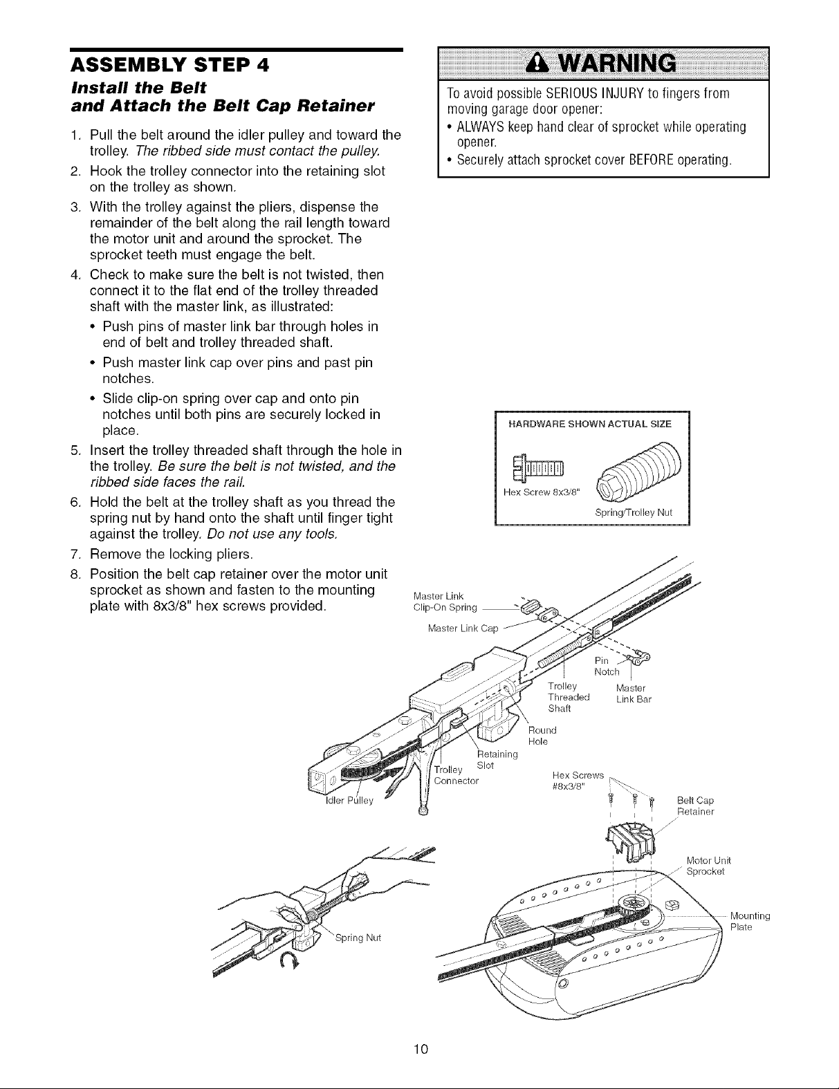
ASSEMBLY STEP 4
Install the Belt
and Attach the Belt Cap Retainer
1. Pull the belt around the idler pulley and toward the
trolley. The ribbed side must contact the pulley.
2. Hook the trolley connector into the retaining slot
on the trolley as shown.
3. With the trolley against the pliers, dispense the
remainder of the belt along the rail length toward
the motor unit and around the sprocket. The
sprocket teeth must engage the belt.
4. Check to make sure the belt is not twisted, then
connect it to the flat end of the trolley threaded
shaft with the master link, as illustrated:
• Push pins of master link bar through holes in
end of belt and trolley threaded shaft.
• Push master link cap over pins and past pin
notches.
• Slide clip-on spring over cap and onto pin
notches until both pins are securely locked in
place.
5. Insert the trolley threaded shaft through the hole in
the trolley. Be sure the belt is not twisted, and the
ribbed side faces the rail.
6. Hold the belt at the trolley shaft as you thread the
spring nut by hand onto the shaft until finger tight
against the trolley. Do not use any tools.
7. Remove the locking pliers.
8. Position the belt cap retainer over the motor unit
sprocket as shown and fasten to the mounting
plate with 8x3/8" hex screws provided.
To avoid possible SERIOUSINJURYto fingers from
moving garage door opener:
• ALWAYSkeephand clear of sprocket while operating
opener.
• Securelyattach sprocket cover BEFOREoperating.
HARDWARE SHOWN ACTUAL SIZE
Hex Screw 8x3/8"
Spring/Trolley Nut
Master Link
Clip-On Spring
Idler P
10
olley
Connector
Retaining
Slot
Pin
Trolley Master
Threaded Link Bar
Shaft
Round
Hole
Notch I
Hex Screws
#8x3/8"
I J
Belt Cap
Retainer
W
jJ
Motor Unit
Mounting
Plate
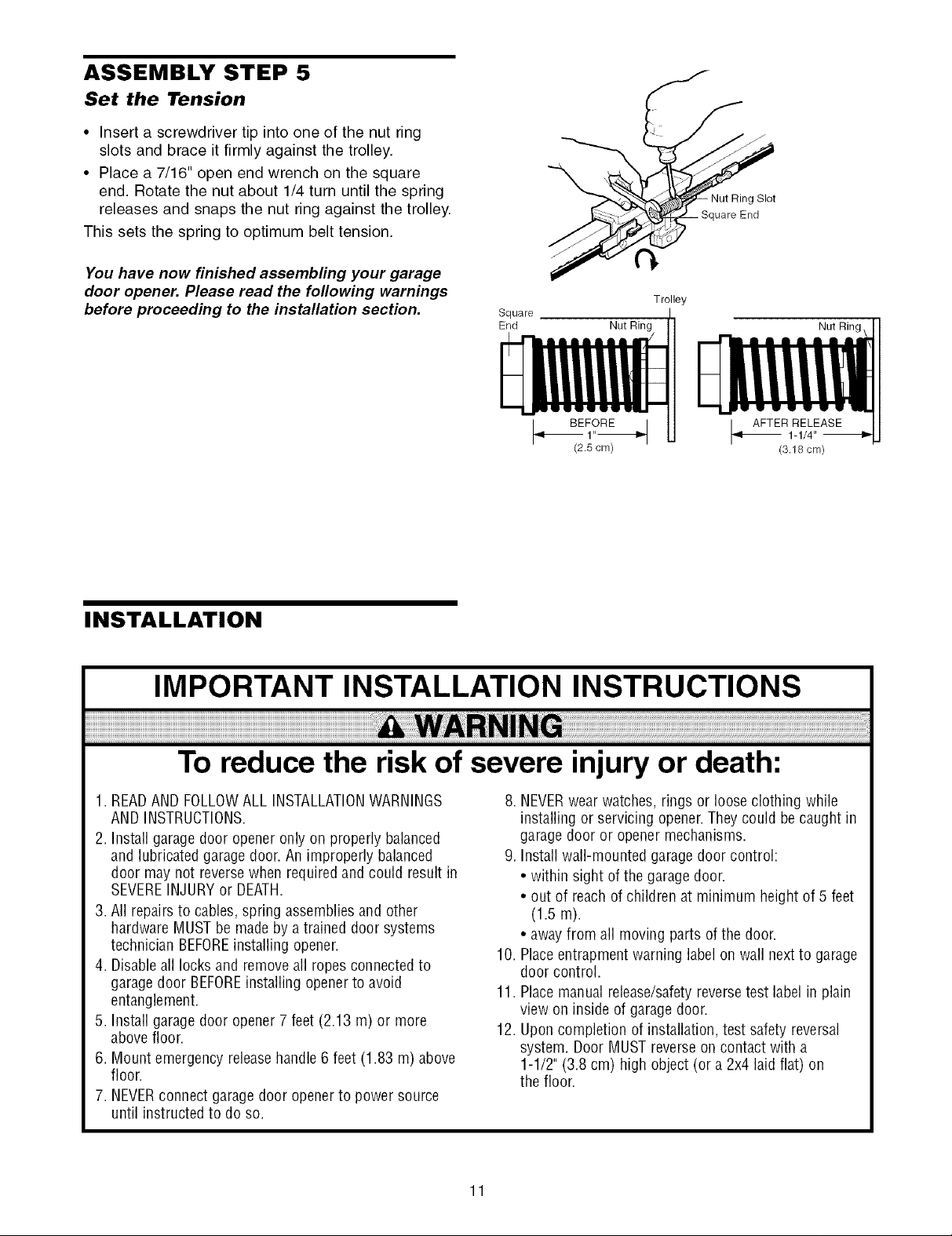
ASSEMBLY STEP 5
Set the Tension
• Insert a screwdriver tip into one of the nut ring
slots and brace it firmly against the trolley.
• Place a 7/16" open end wrench on the square
end. Rotate the nut about 1/4 turn until the spring
releases and snaps the nut ring against the trolley.
This sets the spring to optimum belt tension.
You have now finished assembling your garage
door opener. Please read the following warnings
before proceeding to the installation section.
Square
End
Nut Ring
f
f
Trolley
Nut Ring
INSTALLATION
IMPORTANT INSTALLATION INSTRUCTIONS
To reduce the risk of severe injury or death:
1. READAND FOLLOWALL INSTALLATIONWARNINGS
AND INSTRUCTIONS.
2. Install garage door opener only on properly balanced
and lubricated garage door. Animproperly balanced
door may not reversewhen required and could result in
SEVEREINJURYor DEATH.
3. All repairs to cables,spring assembliesand other
hardwareMUSTbe madeby a trained door systems
technician BEFOREinstalling opener.
4. Disableall locks and removeall ropesconnectedto
garage door BEFOREinstalling opener to avoid
entanglement.
5. Install garage door opener 7feet (2.13 m) or more
above floor.
6. Mount emergency releasehandle 6 feet (1.83 m) above
floor.
7. NEVERconnect garage door openerto power source
until instructed to do so.
8. NEVERwearwatches, rings or looseclothing while
installing or servicing opener.They could be caughtin
garage door or openermechanisms.
9. Installwall-mounted garage door control:
• within sight of the garage door.
• out of reach of children at minimum height of 5 feet
(1.5 m).
• awayfrom all moving parts of the door.
10. Placeentrapment warning label on wall nextto garage
door control.
11. Placemanual release/safetyreversetest label in plain
view on inside of garage door.
12. Uponcompletion of installation, test safety reversal
system. Door MUST reverseoncontact with a
1-1/2" (3.8 cm) high object (or a 2x4 laidflat) on
the floor.
11
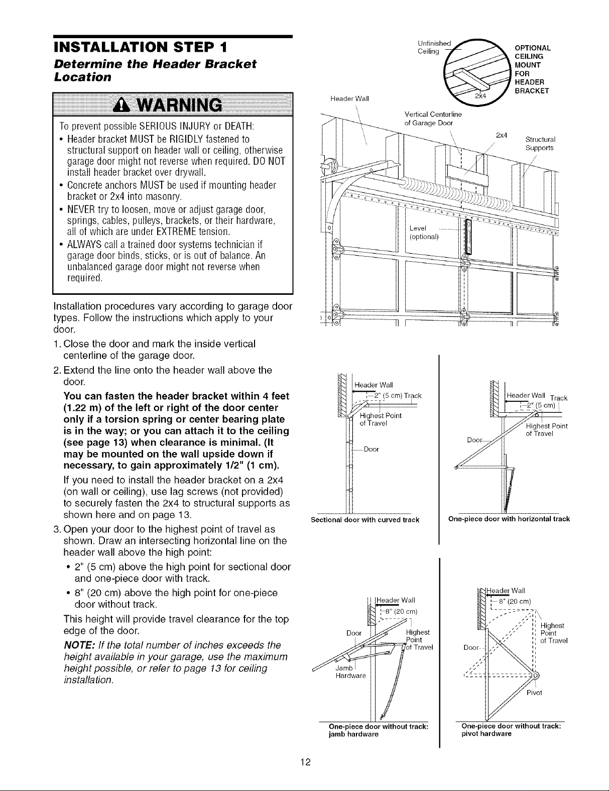
INSTALLATION STEP 1
Determine the Header Bracket
Location
Toprevent possible SERIOUSINJURYor DEATH:
• Headerbracket MUSTbe RIGIDLYfastenedto
structural support on headerwall or ceiling, otherwise
garagedoor might not reversewhen required. DONOT
install headerbracket over drywall.
• Concreteanchors MUSTbe usedif mounting header
bracket or 2x4 into masonry.
• NEVERtry to loosen, move or adjust garagedoor,
springs, cables, pulleys, brackets,or their hardware,
all of which are underEXTREMEtension.
• ALWAYScall a trained door systemstechnician if
garagedoor binds, sticks, or is out of balance.An
unbalancedgarage door might not reversewhen
required.
Installation procedures vary according to garage door
types. Follow the instructions which apply to your
door.
1. Close the door and mark the inside vertical
centerline of the garage door.
2. Extend the line onto the header wall above the
door.
You can fasten the header bracket within 4 feet
(1.22 m) of the left or right of the door center
only if a torsion spring or center bearing plate
is in the way; or you can attach it to the ceiling
(see page 13) when clearance is minimal. (It
may be mounted on the wall upside down if
necessary, to gain approximately 1/2" (1 cm).
If you need to install the header bracket on a 2x4
(on wall or ceiling), use lag screws (not provided)
to securely fasten the 2x4 to structural supports as
shown here and on page 13,
3, Open your door to the highest point of travel as
shown, Draw an intersecting horizontal line on the
header wall above the high point:
• 2" (5 cm) above the high point for sectional door
and one-piece door with track.
• 8" (20 cm) above the high point for one-piece
door without track.
This height will provide travel clearance for the top
edge of the door,
NOTE: If the total number of inches exceeds the
height available in your garage, use the maximum
height possible, or refer to page 13 for ceiling
installation,
Header Wall
Vertical Centerline
of Garage Door
n r
"--_, 2" (5 cm) Track
Header Wall
Highest Point
ofTravel
Door
Sectional door with curved track
_Wall
0oor
Point
Unllnigh_ 2x_
One-piece door with horizontal track
OPTIONAL
CEILING
MOUNT
FOR
HEADER
BRACKET
2x4
/
"_[_, 2" (5 cm)
Header Wall Track
Header Wall
,, 8" (20 cm)
,9, Highest
Structural
Supports
Point
of Travel
One-piece door without track:
jamb hardware
12
One-piece door without track:
pivot hardware
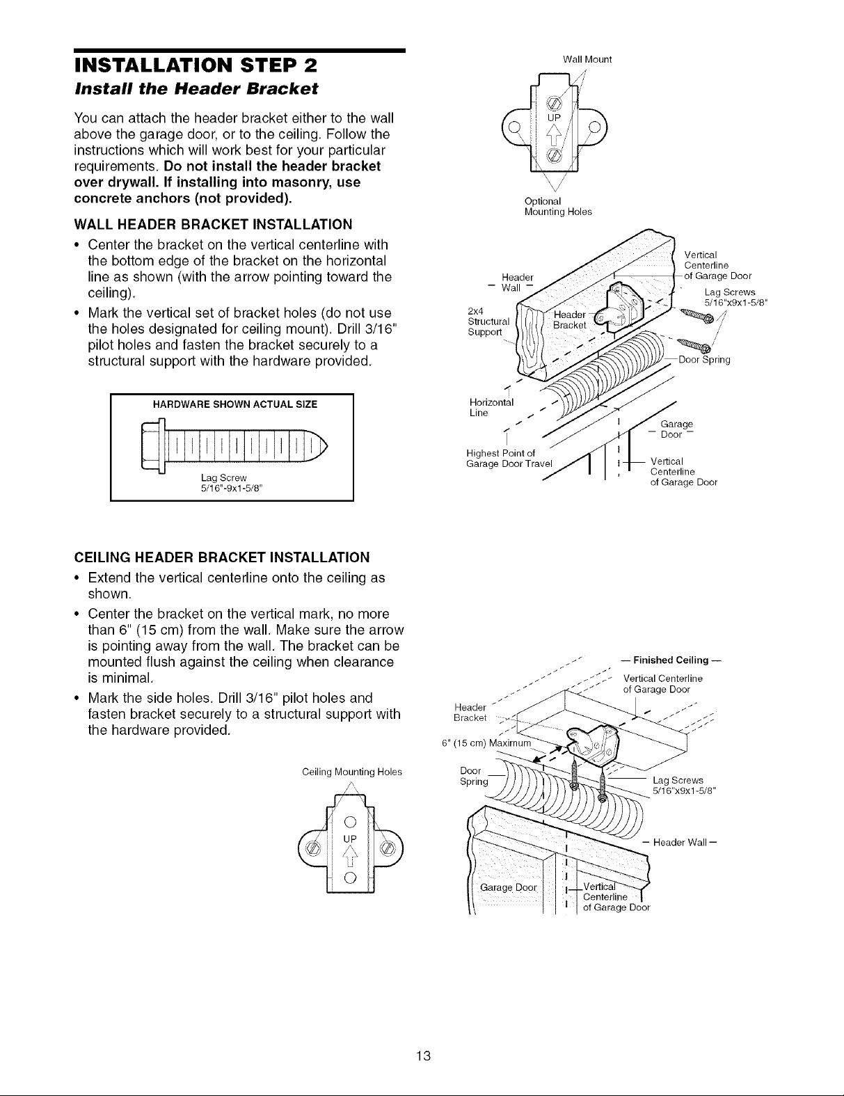
INSTALLATION STEP 2
Install the Header Bracket
You can attach the header bracket either to the wall
above the garage door, or to the ceiling. Follow the
instructions which will work best for your particular
requirements. Do not install the header bracket
over drywall. If installing into masonry, use
concrete anchors (not provided).
WALL HEADER BRACKET INSTALLATION
• Center the bracket on the vertical centerline with
the bottom edge of the bracket on the horizontal
line as shown (with the arrow pointing toward the
ceiling).
• Mark the vertical set of bracket holes (do not use
the holes designated for ceiling mount). Drill 3/16"
pilot holes and fasten the bracket securely to a
structural support with the hardware provided.
- Wall-
2x4
Structural
Support
Optional
Mounting Holes
Header
Wall Mount
/
Vertical
Centerline
Lag Screws
5/16"x9x 1-5/8"
Spring
e Door
/
HARDWARE SHOWN ACTUAL SIZE
I I I I I I I
Lag Screw
5/16"-9xl -5/8"
CEILING HEADER BRACKET INSTALLATION
• Extend the vertical centerline onto the ceiling as
shown.
• Center the bracket on the vertical mark, no more
than 6" (15 cm) from the wall. Make sure the arrow
is pointing away from the wall. The bracket can be
mounted flush against the ceiling when clearance
is minimal.
• Mark the side holes. Drill 3/16" pilot holes and
fasten bracket securely to a structural support with
the hardware provided.
Ceiling Mounting Holes
Horizontal
Line _, /
Highest Point of
Garage Door Travel
Header _
Bracket
6" (15 cm) Maximum
Door
Spring " Lag Screws
/
i
__ __ __ __ Vertical Centerline
_ of Garage Door
iI;S_. -- Finished Ceiling--
-- Door-
Centerline
of Garage Door
Garage
5/16"xgx1-5/8"
13
-- Header Wall --
Centerline
of Garage Door
//
//
//
//
//
//
//
//
//
\1
\1
\t
\1
\t
\1
\1
\t
\1
\1
\t
\1
\t
\t
\t
\1
\t
\t
\t
\t
\1
\t
\I
\1
\t
\t
\t
\1
\1
\t
\t Garage
\1 Door
\1
\t
\1
\t
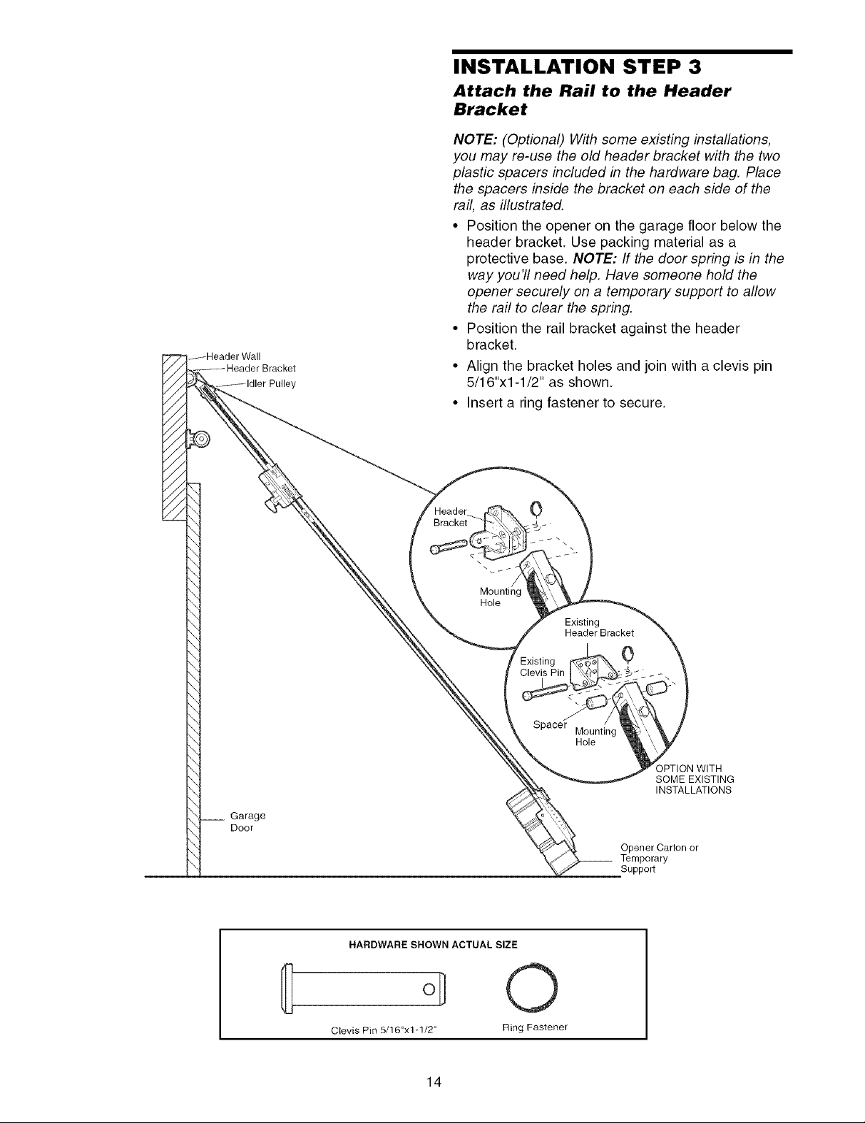
INSTALLATION STEP 3
Attach the Rail to the Header
Bracket
NOTE: (Optional) With some existing installations,
you may re-use the old header bracket with the two
plastic spacers included in the hardware bag. Place
the spacers inside the bracket on each side of the
rail, as illustrated.
• Position the opener on the garage floor below the
header bracket. Use packing material as a
protective base. NOTE: If the door spring is in the
way you'll need help. Have someone hold the
opener securely on a temporary support to allow
the rail to clear the spring.
• Position the rail bracket against the header
bracket.
• Align the bracket holes and join with a clevis pin
5/16"xl-1/2" as shown.
• Insert a ring fastener to secure.
0
\
\
/
Mounting
Hole
Existing
Header Bracket
Existing 0
Clevis Pin
Spacer Mounting
Hole
)PTION WITH
SOME EXISTING
INSTALLATIONS
Opener Carton or
__ Temporary
Support
HARDWARE SHOWN ACTUAL SIZE
Clevis Pin 5/16"x1-1/2" Ring Fastener
14
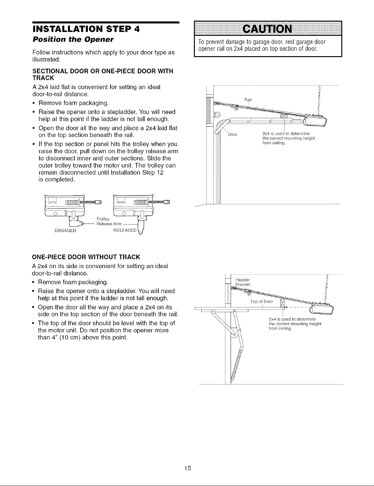
INSTALLATION STEP 4
Position the Opener
Follow instructions which apply to your door type as
illustrated.
SECTIONAL DOOR OR ONE-PIECE DOOR WITH
TRACK
A 2x4 laid flat is convenient for setting an ideal
door-to-rail distance.
• Remove foam packaging.
• Raise the opener onto a stepladder. You will need
help at this point if the ladder is not tall enough.
• Open the door all the way and place a 2x4 laid flat
on the top section beneath the rail.
• If the top section or panel hits the trolley when you
raise the door, pull down on the trolley release arm
to disconnect inner and outer sections. Slide the
outer trolley toward the motor unit. The trolley can
remain disconnected until Installation Step 12
is completed.
To prevent damageto garage door, restgarage door
opener rail on 2x4 placed ontop section of door.
ENGAGED
ONE-PIECE DOOR WITHOUT TRACK
A 2x4 on its side is convenient for setting an ideal
door-to-rail distance.
• Remove foam packaging.
• Raise the opener onto a stepladder. You will need
help at this point if the ladder is not tall enough.
• Open the door all the way and place a 2x4 on its
side on the top section of the door beneath the rail.
• The top of the door should be level with the top of
the motor unit. Do not position the opener more
than 4" (10 cm) above this point.
2x4 is used to determine
the correct mounting height
from ceiling.
15
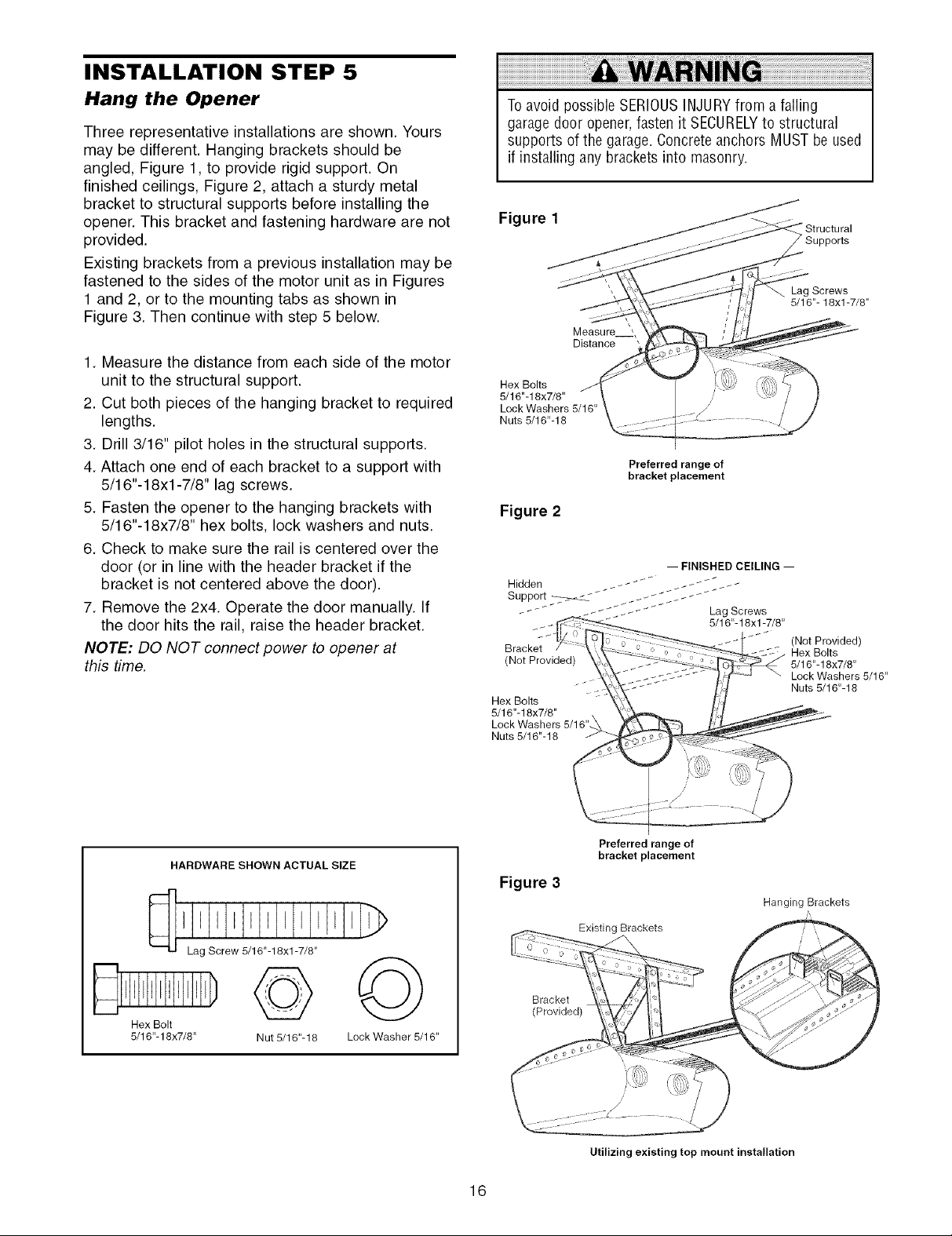
INSTALLATION STEP 5
Hang the Opener
Three representative installations are shown. Yours
may be different. Hanging brackets should be
angled, Figure 1, to provide rigid support. On
finished ceilings, Figure 2, attach a sturdy metal
bracket to structural supports before installing the
opener. This bracket and fastening hardware are not
provided.
Existing brackets from a previous installation may be
fastened to the sides of the motor unit as in Figures
1 and 2, or to the mounting tabs as shown in
Figure 3. Then continue with step 5 below.
1. Measure the distance from each side of the motor
unit to the structural support.
2. Cut both pieces of the hanging bracket to required
lengths.
3. Drill 3/16" pilot holes in the structural supports.
4. Attach one end of each bracket to a support with
5/16"-18xl-7/8" lag screws.
5. Fasten the opener to the hanging brackets with
5/16"-18x7/8" hex bolts, lock washers and nuts.
6. Check to make sure the rail is centered over the
door (or in line with the header bracket if the
bracket is not centered above the door).
7. Remove the 2x4. Operate the door manually. If
the door hits the rail, raise the header bracket.
NOTE: DO NOT connect power to opener at
this time.
Toavoid possible SERIOUSINJURYfrom a falling
garage door opener,fasten it SECURELYto structural
supports of the garage.Concreteanchors MUSTbe used
if installing any bracketsinto masonry.
Figure 1
Lag Screws
5/16"- 18xl -7/8"
Measure
Distance
Hex Bolts
5/16"-18x7/8"
Lock Washers 5/16"
Nuts 5/16"-18
Preferred range of
bracket placement
Figure 2
Bracket
(Not Provided)
Hex Bolts
5/16"-18x7/8"
Nuts 5/16"-18
(Not Provided)
Hex Bolts
5/16"- 18x7/8"
Lock Washers 5/16"
Nuts 5/16"-18
HARDWARE SHOWN ACTUAL SIZE
Hex Bolt
5/16"-18x7/8" Nut 5/16"-18 Lock Washer 5/16"
16
Figure 3
Bracket
(Provided)
Preferred range of
bracket placement
Existing Brackets
Utilizing existing top mount installation
Hanging Brackets
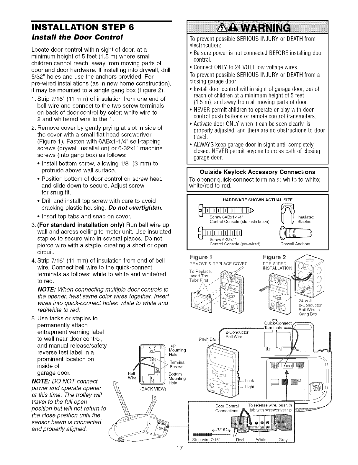
INSTALLATION STEP 6
Install the Door Control
Locate door control within sight of door, at a
minimum height of 5 feet (1.5 m) where small
children cannot reach, away from moving parts of
door and door hardware. If installing into drywall, drill
5/32" holes and use the anchors provided. For
pre-wired installations (as in new home construction),
it may be mounted to a single gang box (Figure 2).
1. Strip 7/16" (11 mm) of insulation from one end of
bell wire and connect to the two screw terminals
on back of door control by color: white wire to
2 and white/red wire to the 1.
2. Remove cover by gently prying at slot in side of
the cover with a small flat head screwdriver
(Figure 1). Fasten with 6ABx1-1/4" self-tapping
screws (drywall installation) or 6-32x1" machine
screws (into gang box) as follows:
• Install bottom screw, allowing 1/8" (3 mm) to
protrude above wall surface.
• Position bottom of door control on screw head
and slide down to secure. Adjust screw
for snug fit.
• Drill and install top screw with care to avoid
cracking plastic housing. Do not overtighten.
• Insert top tabs and snap on cover.
3. (For standard installation only) Run bell wire up
wall and across ceiling to motor unit. Use insulated
staples to secure wire in several places. Do not
pierce wire with a staple, creating a short or open
circuit.
4. Strip 7/16" (11 mm) of insulation from end of bell
wire. Connect bell wire to the quick-connect
terminals as follows: white to white and white/red
to red.
NOTE: When connecting multiple door controls to
the opener, twist same color wires together. Insert
wires into quick-connect holes: white to white and
red/white to red.
5. Use tacks or staples to
permanently attach
entrapment warning label
to wall near door control,
and manual release/safety
reverse test label in a
prominent location on
inside of
garage door.
NOTE: DO NOT connect
power and operate opener (BACKVIEW
at this time. The trolley will
travel to the full open
position but will not return to
the close position until the
sensor beam is connected
and properly aligned.
Top
Mounting
Hole
Terminal
Screws
Bottom
Mounting
Hole
17
Toprevent possible SERIOUSINJURYor DEATHfrom
electrocution:
• Besure power is not connected BEFOREinstalling door
control.
• ConnectONLYto 24 VOLTlow voltage wires.
Toprevent possible SERIOUSINJURYor DEATHfrom a
closing garagedoor:
• Install door control within sight of garage door,out of
reachof children at a minimum height of 5 feet
(1.5 m), andaway from all moving parts of door.
• NEVERpermit children to operateor playwith door
control push buttons or remote control transmitters.
• Activate door ONLYwhen it can be seen clearly,is
properly adjusted, andthere are no obstructions to door
travel.
• ALWAYSkeep garagedoor in sight until completely
closed. NEVERpermit anyone to cross path of closing
garagedoor.
Outside Keylock Accessory Connections
To opener quick-connect terminals: white to white;
white/red to red.
HARDWARE SHOWN ACTUAL SIZE
I I I_Iclr:lwl1_:1_IxI1[:I:, ! 111-_
Control Console (std installation)
Control Console (pre-wired)
Figure 1
REMOVE & REPLACE COVER
To Replace,
Insert Top
Tabs First
/,, ///'
_._- 7/16 '-'
Strip wire 7/16" Red White Grey
Figure 2
PRE-WIRED
INSTALLATION
Insulated
Staples
Drywall Anchors
24 Volt
2-Conductor
Bell Wire in
Gang Box
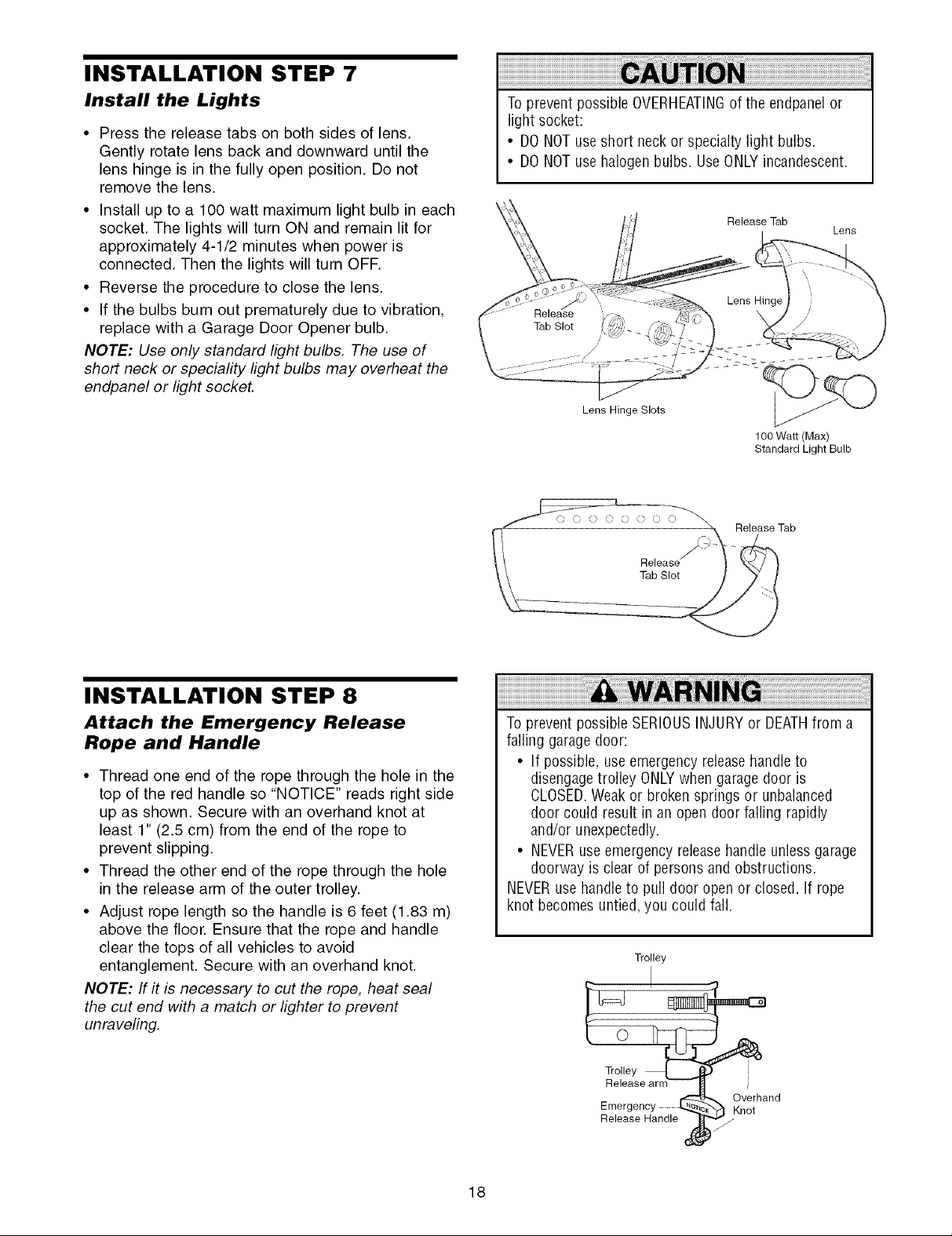
INSTALLATION STEP 7
Install the Lights
• Press the release tabs on both sides of lens.
Gently rotate lens back and downward until the
lens hinge is in the fully open position. Do not
remove the lens.
• Install up to a 100 watt maximum light bulb in each
socket. The lights will turn ON and remain lit for
approximately 4-1/2 minutes when power is
connected. Then the lights will turn OFF.
• Reverse the procedure to close the lens.
• If the bulbs burn out prematurely due to vibration,
replace with a Garage Door Opener bulb.
NOTE: Use only standard light bulbs. The use of
short neck or speciafity light bulbs may overheat the
endpanel or light socket.
Toprevent possible OVERHEATINGof the endpanelor
light socket:
• DONOTuseshort neckor specialty light bulbs.
• DONOTuse halogenbulbs. UseONLYincandescent.
Release Tab
Lens Hinge Slots
100 Watt (Max)
Standard Light Bulb
Release Tab
Lens
INSTALLATION STEP 8
Attach the Emergency Release
Rope and Handle
• Thread one end of the rope through the hole in the
top of the red handle so "NOTICE" reads right side
up as shown. Secure with an overhand knot at
least 1" (2.5 cm) from the end of the rope to
prevent slipping.
• Thread the other end of the rope through the hole
in the release arm of the outer trolley.
• Adjust rope length so the handle is 6 feet (1.83 m)
above the floor. Ensure that the rope and handle
clear the tops of all vehicles to avoid
entanglement. Secure with an overhand knot.
NOTE: If it is necessary to cut the rope, heat seal
the cut end with a match or lighter to prevent
unraveling.
L_ Release
Tab Slot
To prevent possibleSERIOUSINJURYor DEATHfrom a
falling garage door:
• If possible, useemergencyreleasehandleto
disengagetrolley ONLYwhengarage door is
CLOSED.Weak or broken springs or unbalanced
door could result in an open door falling rapidly
and/or unexpectedly.
• NEVERuseemergency releasehandleunlessgarage
doorway is clear of persons and obstructions.
NEVERuse handleto pull door open or closed. If rope
knot becomes untied,you could fall.
Trolley
18
Release Handle
Emergency _ _K verhandnot
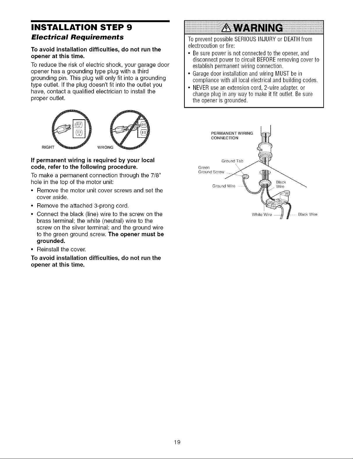
INSTALLATION STEP 9
Electrical Requirements
To avoid installation difficulties, do not run the
opener at this time.
To reduce the risk of electric shock, your garage door
opener has a grounding type plug with a third
grounding pin. This plug will only fit into a grounding
type outlet. If the plug doesn't fit into the outlet you
have, contact a qualified electrician to install the
proper outlet.
If permanent wiring is required by your local
code, refer to the following procedure.
To make a permanent connection through the 7/8"
hole in the top of the motor unit:
• Remove the motor unit cover screws and set the
cover aside.
• Remove the attached 3-prong cord.
• Connect the black (line) wire to the screw on the
brass terminal; the white (neutral) wire to the
screw on the silver terminal; and the ground wire
to the green ground screw. The opener must be
grounded.
• Reinstall the cover.
To avoid installation difficulties, do not run the
opener at this time.
To prevent possible SERIOUSINJURYor DEATHfrom
electrocution or fire:
• Besure power is not connected to the opener, and
disconnect power to circuit BEFOREremoving cover to
establish permanentwiring connection.
• Garagedoor installation andwiring MUSTbe in
compliance with all localelectrical and building codes.
• NEVERusean extensioncord, 2-wire adapter,or
changeplug in anyway to makeit fit outlet. Besure
the opener is grounded.
PERMANENT WiRiNG
CONNECTION
Ground Tab
Green
Ground Screw
Ground Wire Wire
N\
Black
White Wire
19
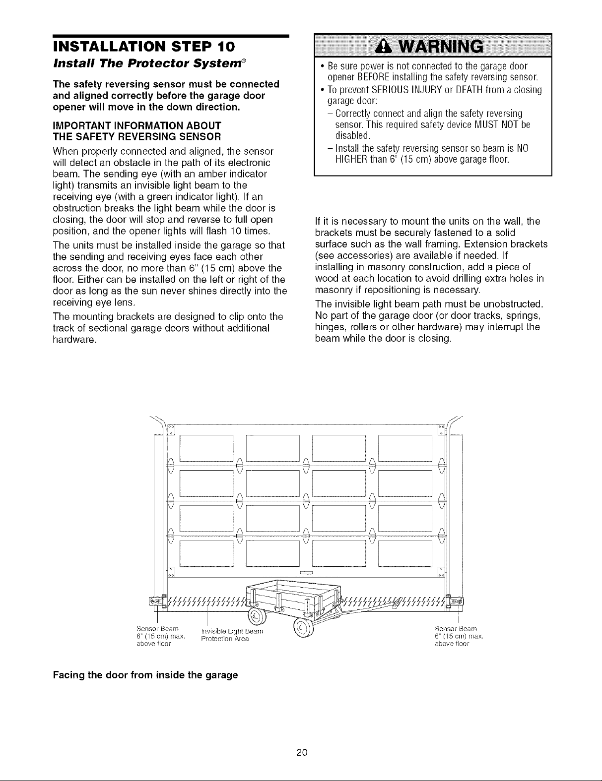
INSTALLATION STEP 10
Install The Protector System ®
The safety reversing sensor must be connected
and aligned correctly before the garage door
opener will move in the down direction.
IMPORTANT INFORMATION ABOUT
THE SAFETY REVERSING SENSOR
When properly connected and aligned, the sensor
will detect an obstacle in the path of its electronic
beam. The sending eye (with an amber indicator
light) transmits an invisible light beam to the
receiving eye (with a green indicator light). If an
obstruction breaks the light beam while the door is
closing, the door will stop and reverse to full open
position, and the opener lights will flash 10 times.
The units must be installed inside the garage so that
the sending and receiving eyes face each other
across the door, no more than 6" (15 cm) above the
floor. Either can be installed on the left or right of the
door as long as the sun never shines directly into the
receiving eye lens.
The mounting brackets are designed to clip onto the
track of sectional garage doors without additional
hardware.
• Be sure power is not connectedto the garage door
opener BEFOREinstalling the safety reversingsensor
• To prevent SERIOUSINJURYor DEATHfrom a closing
garagedoor:
- Correctly connect and alignthe safety reversing
sensor This requiredsafety device MUSTNOTbe
disabled.
- Install the safety reversingsensor so beam is NO
HIGHERthan 6" (15 cm) above garagefloor
If it is necessary to mount the units on the wall, the
brackets must be securely fastened to a solid
surface such as the wall framing. Extension brackets
(see accessories) are available if needed. If
installing in masonry construction, add a piece of
wood at each location to avoid drilling extra holes in
masonry if repositioning is necessary.
The invisible light beam path must be unobstructed.
No part of the garage door (or door tracks, springs,
hinges, rollers or other hardware) may interrupt the
beam while the door is closing.
Sensor Beam Invisible Light Beam
6" (15 cm) max, Protection Area
above floor
Facing the door from inside the garage
2O
Sensor Beam
6" (15 cm) max,
above floor
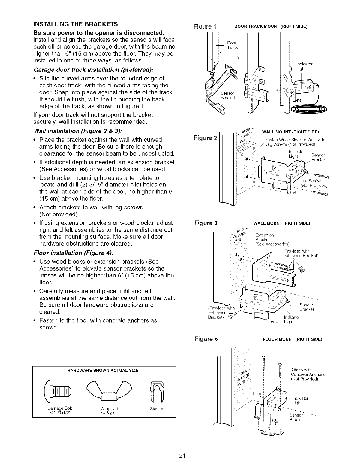
INSTALLING THE BRACKETS
Be sure power to the opener is disconnected.
Install and align the brackets so the sensors will face
each other across the garage door, with the beam no
higher than 6" (15 cm) above the floor. They may be
installed in one of three ways, as follows.
Garage door track installation (preferred):
• Slip the curved arms over the rounded edge of
each door track, with the curved arms facing the
door. Snap into place against the side of the track.
It should lie flush, with the lip hugging the back
edge of the track, as shown in Figure 1.
If your door track will not support the bracket
securely, wall installation is recommended.
Wall installation (Figure 2 & 3):
• Place the bracket against the wall with curved
arms facing the door. Be sure there is enough
clearance for the sensor beam to be unobstructed.
• If additional depth is needed, an extension bracket
(See Accessories) or wood blocks can be used.
• Use bracket mounting holes as a template to
locate and drill (2) 3/16" diameter pilot holes on
the wall at each side of the door, no higher than 6"
(15 cm) above the floor.
• Attach brackets to wall with lag screws
(Not provided).
• If using extension brackets or wood blocks, adjust
right and left assemblies to the same distance out
from the mounting surface. Make sure all door
hardware obstructions are cleared.
Floor installation (Figure 4):
• Use wood blocks or extension brackets (See
Accessories) to elevate sensor brackets so the
lenses will be no higher than 6" (15 cm) above the
floor.
• Carefully measure and place right and left
assemblies at the same distance out from the wall.
Be sure all door hardware obstructions are
cleared.
• Fasten to the floor with concrete anchors as
shown.
Figure
Figure 2
DOOR TRACK MOUNT (RIGHT SIDE)
Door
Track
Sensor
Bracket
WALL MOUNT (RIGHT SIDE)
Fasten Wood Block to Wall with
_Lag Screws (Not Provided)
_ , J Bracket
Indicator
Light
Indicator
LP,ht Sensor
__ ([_!ot Pro\_ided)
Lens ..... _,._
Figure 3 WALL MOUNT (RIGHT SIDE)
Extension
Bracket
(See Accessories)
i (Provided with
Extension Bracket)
(Provided with
Extension
Bracket) _"
Lens
Sensor
Bracket
Indicator
Light
c_r_
HARDWARE SHOWN ACTUAL SIZE
Carriage Bolt Wing Nut
1/4"-20xl/2" 1/4"-20
fl
Staples
Figure 4 FLOOR MOUNT (RIGHT SIDE)
l Attach with
i (Not Provided)
J
21
Concrete Anchors
Light
Bracket
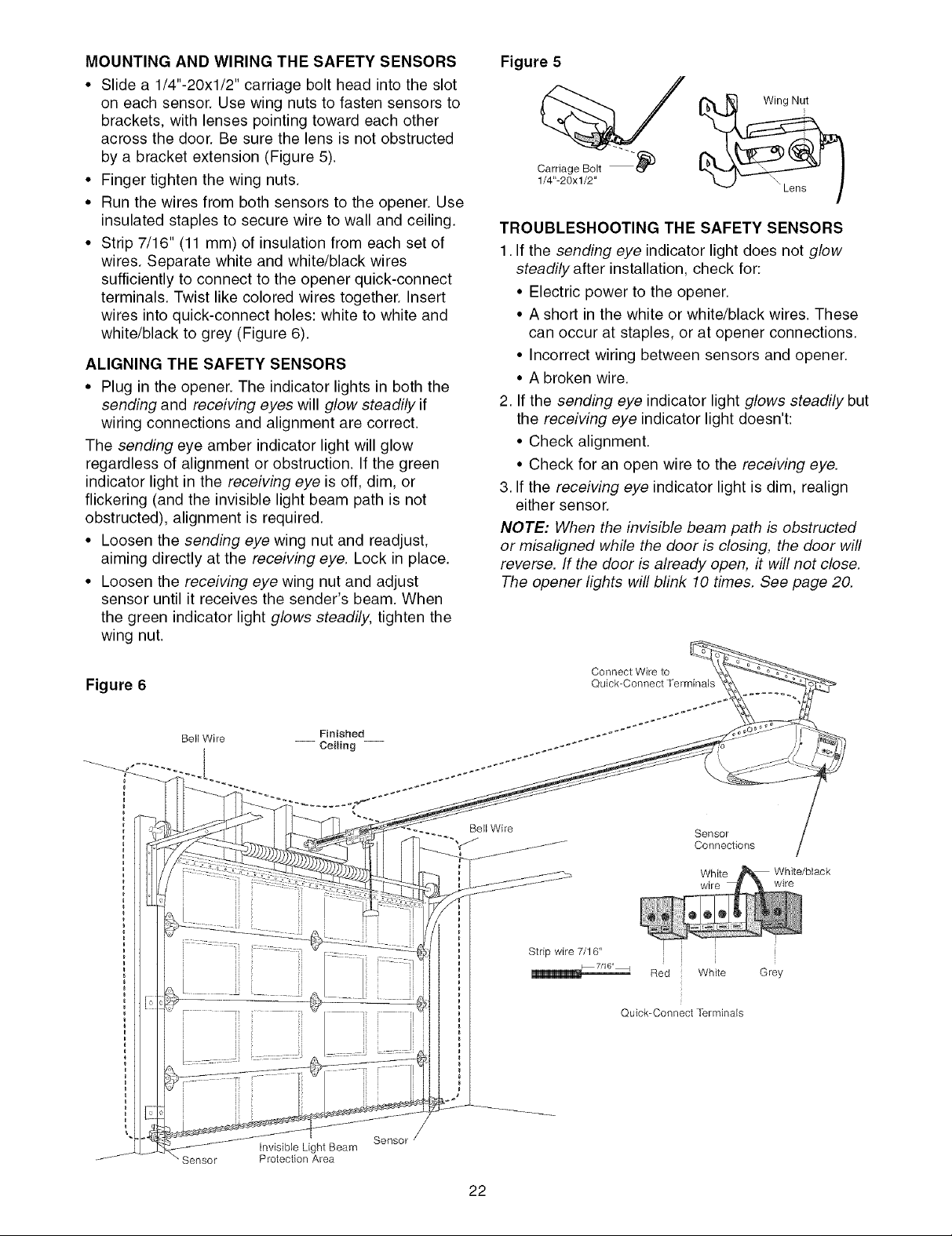
MOUNTING AND WIRING THE SAFETY SENSORS
• Slide a 1/4"-20xl/2" carriage bolt head into the slot
on each sensor. Use wing nuts to fasten sensors to
brackets, with lenses pointing toward each other
across the door. Be sure the lens is not obstructed
by a bracket extension (Figure 5).
• Finger tighten the wing nuts.
• Run the wires from both sensors to the opener. Use
insulated staples to secure wire to wall and ceiling.
• Strip 7/16" (11 mm) of insulation from each set of
wires. Separate white and white/black wires
sufficiently to connect to the opener quick-connect
terminals. Twist like colored wires together. Insert
wires into quick-connect holes: white to white and
white/black to grey (Figure 6).
ALIGNING THE SAFETY SENSORS
• Plug in the opener. The indicator lights in both the
sending and receiving eyes will glow steadily if
wiring connections and alignment are correct.
The sending eye amber indicator light will glow
regardless of alignment or obstruction. If the green
indicator light in the receiving eye is off, dim, or
flickering (and the invisible light beam path is not
obstructed), alignment is required.
• Loosen the sending eye wing nut and readjust,
aiming directly at the receiving eye. Lock in place.
• Loosen the receiving eye wing nut and adjust
sensor until it receives the sender's beam. When
the green indicator light glows steadily, tighten the
wing nut.
Figure 5
Carriage Bolt _)
1/4"-20xl/2"
TROUBLESHOOTING THE SAFETY SENSORS
1. If the sending eye indicator light does not glow
steadily after installation, check for:
• Electric power to the opener.
• A short in the white or white/black wires. These
can occur at staples, or at opener connections.
• Incorrect wiring between sensors and opener.
• A broken wire.
2. If the sending eye indicator light glows steadily but
the receiving eye indicator light doesn't:
• Check alignment.
• Check for an open wire to the receiving eye.
3. If the receiving eye indicator light is dim, realign
either sensor.
NOTE: When the invisible beam path is obstructed
or misaligned while the door is closing, the door will
reverse. If the door is already open, it will not close.
The opener lights will blink 10 times. See page 20.
Figure 6
Bell Wire
Finished _*
Stripwire 7/16"
Connect Wire to
Quick-Connect Terminals
Quick-Connect Terminals
White
wire
White/black
wire
i
Grey
Sensor
Invisible Light Beam
Protection Area
Sensor
22
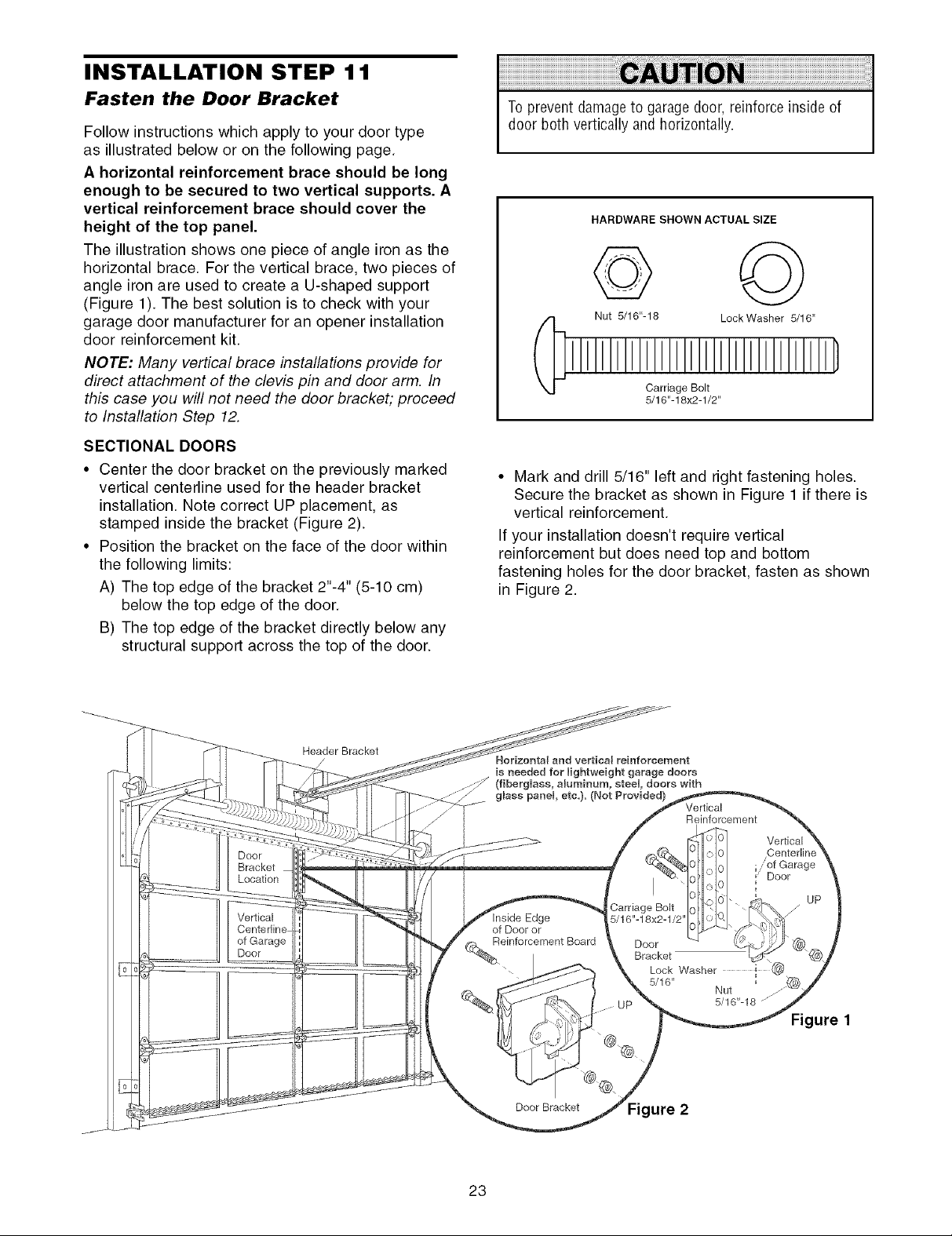
INSTALLATION STEP 1 1
Fasten the Door Bracket
Follow instructions which apply to your door type
as illustrated below or on the following page.
A horizontal reinforcement brace should be long
enough to be secured to two vertical supports. A
vertical reinforcement brace should cover the
height of the top panel.
The illustration shows one piece of angle iron as the
horizontal brace. For the vertical brace, two pieces of
angle iron are used to create a U-shaped support
(Figure 1). The best solution is to check with your
garage door manufacturer for an opener installation
door reinforcement kit.
NOTE: Many vertical brace installations provide for
direct attachment of the clevis pin and door arm. In
this case you will not need the door bracket; proceed
to Installation Step 12.
SECTIONAL DOORS
• Center the door bracket on the previously marked
vertical centerline used for the header bracket
installation. Note correct UP placement, as
stamped inside the bracket (Figure 2).
• Position the bracket on the face of the door within
the following limits:
A) The top edge of the bracket 2"-4" (5-10 cm)
below the top edge of the door.
B) The top edge of the bracket directly below any
structural support across the top of the door.
To prevent damageto garage door, reinforceinside of
door both vertically and horizontally.
HARDWARE SHOWN ACTUAL SIZE
© ©
Nut 5/16"-18 LockWasher 5/16"
Carriage Bolt
5/16"-18x2-1/2"
• Mark and drill 5/16" left and right fastening holes.
Secure the bracket as shown in Figure 1 if there is
vertical reinforcement.
If your installation doesn't require vertical
reinforcement but does need top and bottom
fastening holes for the door bracket, fasten as shown
in Figure 2.
Door
Bracket
Location
Vertical
of Garage
Door
Header Bracket
Horizontal and vertical reinforcement
is needed for lightweight garage doors
(fibergUass, amuminum, steeU, doors with
glass panel etc.). (Not Provided)
Edge
of Door or
einforcement Board
Door Bracket ure 2
Carriage Bolt
5/16"-18x2-1/2"
23
Door
Bracket
Lock Washer
5/16"
Vertical
Reinforcement
Nut
5/16"-18 .......""
Vertical
Centerlin
.; of Garage
Door
Figure 1
UP
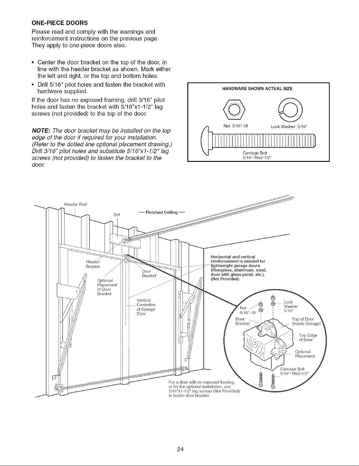
ONE-PIECEDOORS
Please read and comply with the warnings and
reinforcement instructions on the previous page.
They apply to one-piece doors also.
• Center the door bracket on the top of the door, in
line with the header bracket as shown. Mark either
the left and right, or the top and bottom holes.
• Drill 5/16" pilot holes and fasten the bracket with
hardware supplied.
If the door has no exposed framing, drill 3/16" pilot
holes and fasten the bracket with 5/16"x1-1/2" lag
screws (not provided) to the top of the door.
HARDWARE SHOWN ACTUAL SIZE
© ©
NOTE: The door bracket may be installed on the top
edge of the door if required for your installation.
(Refer to the dotted line optional placement drawing.)
Drill 3/16" pilot holes and substitute 5/16"x1-1/2" lag
screws (not provided) to fasten the bracket to the
door.
Header Wall
[
Header
Bracket
Optional
Placement
of Door
Bracket
2x4
Door
Bracket
Vertical
of Garage
Door
Nut 5/16"-16 Lock Washer 5/16"
Carriage Bolt
5/16"-18x2-1/2"
HodzontaU and verticaU
reinforcement is needed for
(fiberglass, aUuminum, steel,
door with gUass panel etc.).
(Not Provided)
Door
Bracket
doors
' 5/16"
i
Lock
Washer
Top of Door
(Inside
For a door with no exposed framing,
or for the optional installation, use
5/16"x1-1/2" lag screws (Not Provided)
to fasten door bracket.
24
Top Edge
of Door
Optional
Placement
Carriage Bolt
5/16"-18x2-1/2"
 Loading...