

Page 1
Owner’s Manual/Manual Del Propietario
CRflFTSMBN
«315MHz GARAGE DOOR OPENER
ABRIDOR DE PUERTA DE COCHERA
For Residential Use Oniy/Sólo para uso residencial
Model/Modelo 139.53918D
iVi№
Q
00
5
Read and follow all safety rules
and operating instructions before
first use of this product.
Fasten the manual near the garage
door after installation.
Periodic checks of the opener are
required to ensure safe operation.
os
Sears, Roebuck and Co., Hoffman Estates, IL 60179 U.S.A
www.sears.com/craftsman
Leer y seguir todas las reglas de
seguridad y las instrucciones de
operación antes de usar este
producto por primera vez.
Guardar este manual cerca de la
puerta de la cochera.
Se deben realizar revisiones
periódicas del abridor de puertas
para asegurar su operación
segura.
Page 2

TABLE OF CONTENTS
Introduction 2-7
Safety symbol review and signal word review
Preparing your garage door............................................3
Tools needed...................................................................3
Planning ......................................................................4-5
Carton inventory .............................................................6
Hardware inventory.........................................................7
................
2
Assembly 8-11
Assemble the rail and Install the trolley
Fasten the rail to the motor unit
Install the idler pulley
Install the belt and attach the belt cap retainer
Set the tension..............................................................11
......................................................
..........................
.....................................
.............
8
9
9
10
Installation 11-26
Installation safety instructions
Determine the header bracket location.........................12
Install the header bracket
Attach the rail to the header bracket
Position the opener.......................................................15
Hang the opener
Install the control console
Install the battery...........................................................18
Install the lights
Attach the emergency release rope and handle
Electrical requirements
Install The Protector System® (safety sensors) . . . .20-22
Fasten the door bracket...........................................23-24
Connect the door arm to the trolley
..........................................................
............................................................
.....................................
............................................
.............................
............................................
...........
................................................
.........................
25-26
11
13
14
16
17
18
18
19
Adjustment 27-29
Program the travel limits ...........................................27
Setting the force
Test the safety reversal system.................................29
Test The Protector System® (safety sensors)
........................................................
.........
28
29
Operation 30-36
Operation safety instructions.....................................30
Using your garage door opener
Using the wall-mounted control console
Care of your opener
To open the door manually
Battery backup
Having a problem (Troubleshooting)
Diagnostic chart.........................................................35
LCD motion detecting control
console messages.....................................................36
..................................................
..........................................................
................................
....................
......................................
........................
30
32
32
33
34
Programming 37-38
To add or reprogram a hand-held remote control . . .37
To erase all codes from motor unit memory ..............37
3-Function remotes ...................................................37
To add, reprogram or change a
Keyless Entry PIN
....................................................
38
Repair Parts 39-40
Rail assembly parts ..................................................39
Installation parts
Motor unit assembly parts
........................................................
........................................
39
40
Accessories 41
Warranty 41
Repair Parts & Service Back Cover
31
INTRODUCTION
Safety Symbol Review
and Signal Word Review
This garage door opener has been designed and tested to offer safe service provided it is installed, operated,
maintained and tested in strict accordance with the instructions and warnings contained in this manual.
¿k WARNING
Mechanical
A WARNING
Electrical
CAUTION
When you see these Safety Symbols and Signal Words
on the following pages, they will alert you to the
possibility of serious injury or death if you do not
comply with the warnings that accompany them. The
hazard may come from something mechanical or from
electric shock. Read the warnings carefully.
When you see this Signal Word on the following pages, it
will alert you to the possibility of damage to your garage
door and/or the garage door opener if you do not comply
with the cautionary statements that accompany it. Read
them carefully.
Page 3
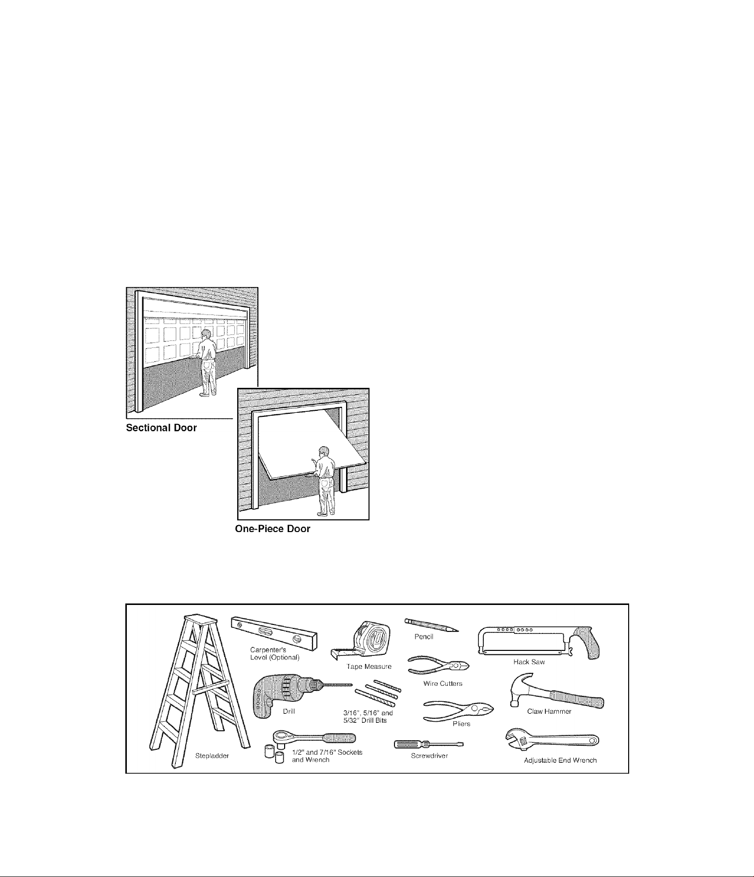
Preparing your garage door
Before you begin:
• Disable locks.
• Remove any ropes connected to garage door.
• Complete the following test to make sure your garage
door is balanced and is not sticking or binding:
1. Lift the door about halfway as shown. Release the
door. If balanced, it should stay in place, supported
entirely by its springs.
2. Raise and lower the door to see if there is any
binding or sticking.
If your door binds, sticks, or is out of balance, call a
trained door systems technician.
A WARNING
To prevent possible SERIOUS INJURY OR DEATH:
• ALWAYS call a trained door systems technician if garage
door binds, sticks, or is out of balance. An unbalanced
garage door may not reverse when required.
• NEVER try to loosen, move or adjust garage door, door
springs, cables, pulleys, brackets or their hardware, all of
which are under EXTREME tension.
• Disable ALL locks and remove ALL ropes connected to
garage door BEEORE Installing and operating garage door
opener to avoid entanglement.
CAUTION
To prevent damage to garage door and opener:
• ALWAYS disable locks BEFORE installing and operating the
opener.
• ONLY operate garage door opener at 120V, 60 Elz to avoid
malfunction and damage.
Tools needed
During assembly, installation and adjustment of the
opener, instructions will call for hand tools as
illustrated below.
Page 4
Planning
Identify the type and height of your garage door. Survey
your garage area to see if any of the conditions below
apply to your installation. Additional materials may be
required. You may find it helpful fo refer back to this page
and the accompanying illustrations as you proceed with
the installation of your opener.
Depending on your requirements, there are several
installation steps which may call for materials or
hardware not included in the carton.
• Installation Step 1 - Look at the wall or ceiling above
the garage door. The header bracket must be securely
fastened to structural supports.
• Installation Step 5 - Do you have a finished ceiling in
your garage? If so, a support bracket and additional
fastening hardware may be required.
• Installation Step 11 ™ Depending upon garage
construction, extension brackets or wood blocks may
be needed to install sensors.
• Installation Step 11 ~ Alternate floor mounting of the
safety reversing sensor will require hardware not
provided.
Do you have an access door in addition to the garage
door? If not, Model 139.53702 Emergency Key
Release is required. See Accessories page.
Look at the garage door where it meets the floor. Any
gap between the floor and the bottom of the door must
not exceed 1/4" (6 mm). Otherwise, the safety reversal
system may not work properly. See Adjustment Step 3.
Floor or door should be repaired.
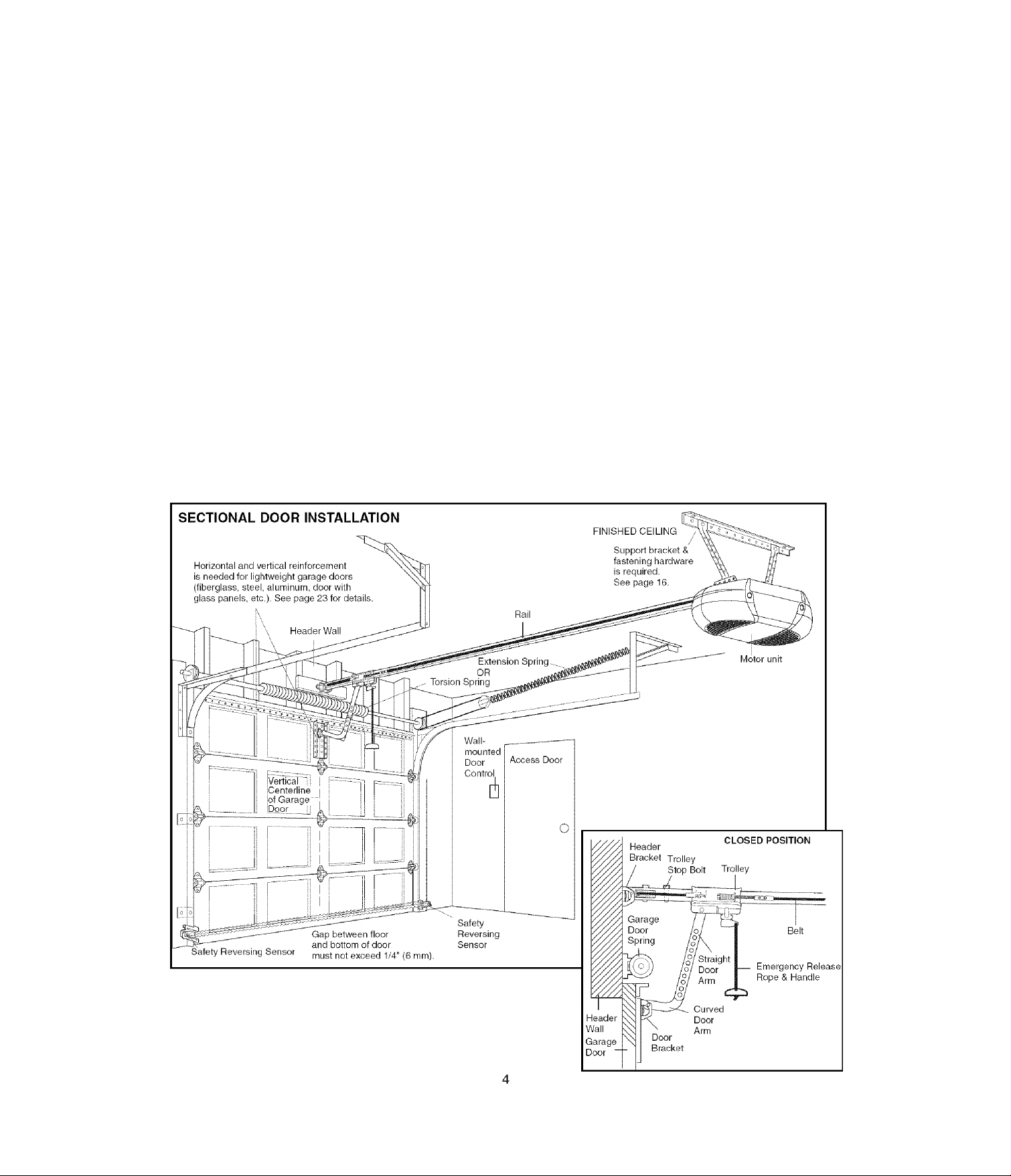
SECTIONAL DOOR INSTALLATIONS
• Do you have a steel, aluminum, fiberglass or glass
panel door? If so, horizonfal and verfical
reinforcement is required (Installation Step 12).
• The opener should be installed above the center of fhe
door. If there is a torsion spring or center bearing plate
in the way of the header bracket, it may be installed
within 4 feet (1.22 m) to the left or right of the door
center. See Installation Steps 1 and 12.
• If your door is more than 7 feet (2.13 m) high, see rail
extension kits listed on Accessories page.
Page 5
Planning (Continued)
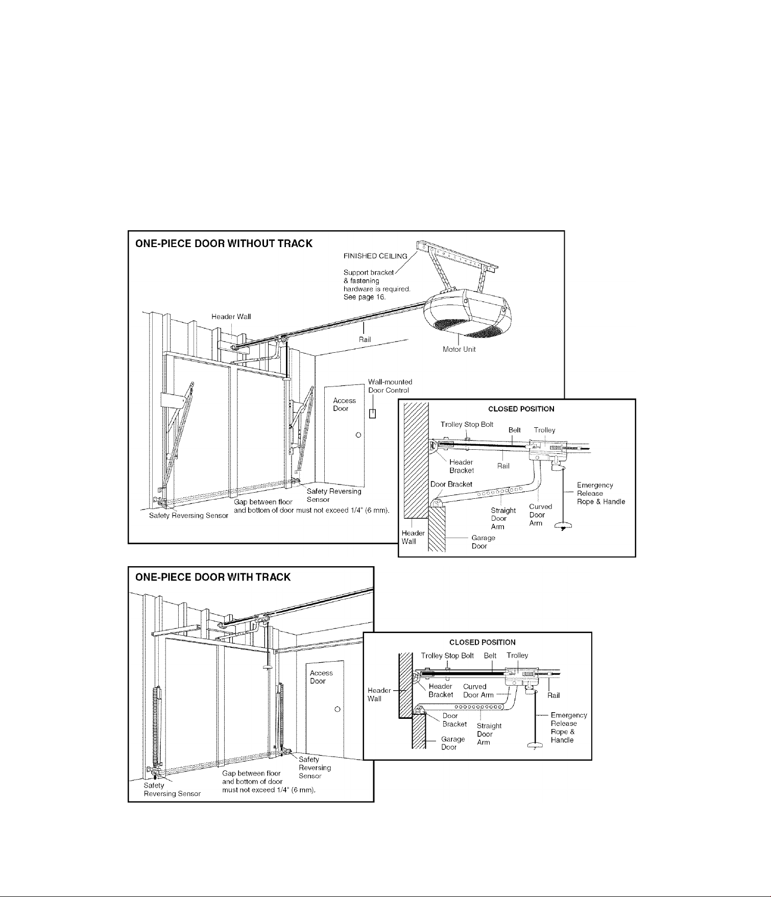
ONE-PIECE DOOR INSTALLATIONS
• Generally, a one-piece door does not require
reinforcement, if your door is lightweight, refer to the
information reiating to sectional doors in Instailation
Step 12.
• Depending on your door’s construction, you may need
additional mounting hardware for the door bracket
(Step 12).
A WARNING
Without a properly working safehy reversal system, persons
(particularly small children) could be SERIOUSLY INJURED
or KILLED by a closing garage door.
• The gap between the bottom of the garage door and the
floor MUST NOT exceed 1/4" (6 mm). Otherwise, the safety
reversal system may not work properly.
• The floor or the garage door MUST be repaired to eliminate
the gap.
Page 6
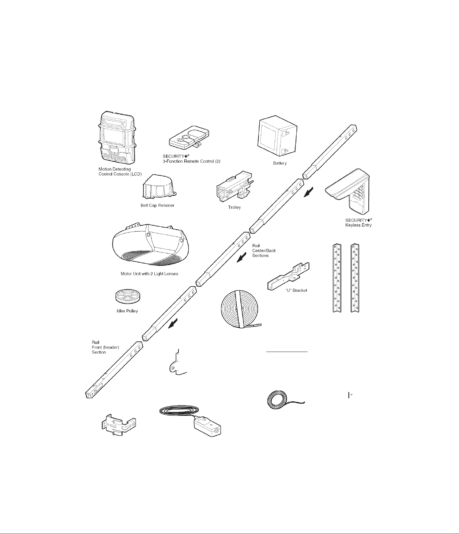
Carton Inventory
Your garage door opener is packaged in one carton
which contains the motor unit and all parts illustrated
below. Accessories will depend on the model purchased.
If anything is missing, carefully check the packing
material. Parts may be stuck in the foam. Hardware for
assembly and installation is shown on the next page.
Save the carton and packing material until installation
and adjustment is complete.
Safety Reversing
Sensor Bracket (2)
Header Bracket
The Protector System®
(2) Safety Reversing Sensors
(1 Sending Eye and 1 Receiving Eye)
with 2-Conductor White & White/Black
Bell Wire attached
Belt
10 IC jl
..
Door Bracket
Curved Door
Arm Section
2-Conductor Bell Wire
White & White/Red
Safety Labels
and
Literature
Hanging Brackets
/
/
i
Straight Door
Arm Section
Page 7
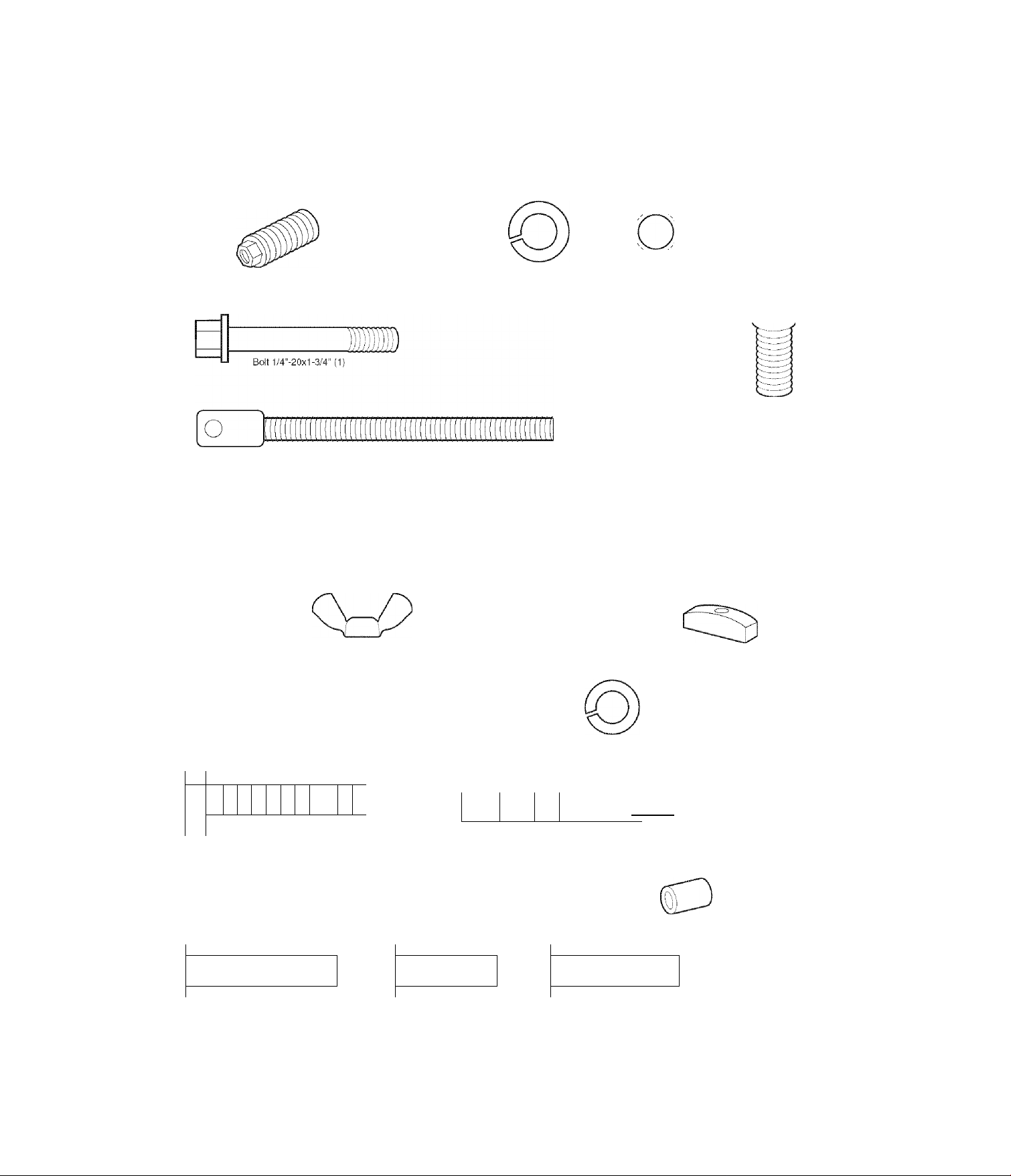
Hardware Inventory
Separate all hardware and group as shown below for the assembly and installation procedures.
ASSEMBLY HARDWARE
o
Sphng/Trolley Nut (1)
Carriage Bolt
1/4"-20x1/2" (2)
Lock Nut
1/4“-20 (2)
Trolley Threaded Shaft (1)
INSTALLATION HARDWARE
Wing Nut
1/4“-20 (2)
Lock Washer
3/8" (1)
o ®
Ring
Fastener (3)
Nut 5/16"-18(6)
Nut
3/8" (1)
Master
Link (2)
Idler Bolt (1)
Handle
1 1 1 1 1 1 1
L
jr
\j
Clevis Pin
5/16"x1-1/2" (1)
Lag Screw
5/16"-9x1-5/8“(2)
Lag Screw
Carriage Bolt
5/16"-18x2-1/2" (2)
I I
]>
Hex Bolt
5/16"-18x7/8" (4)
1 1
[i>
0
\
Clevis Pin
5/16“x1" (1)
MM 1 1 ! I
Screw
6ABX1-1/4" (2)
Drywall Anchors (2)
O
Lock Washer 5/16" (7)
1 1 17> £
/
y
Clevis Pin
5/16"x1-1/4" (1)
^llTiiniIìEIììIIiìIÌ
Screw 6-32x1 ■ (2)
Spacer (2)
o
Insulated
Staples (30)
Rope
Page 8
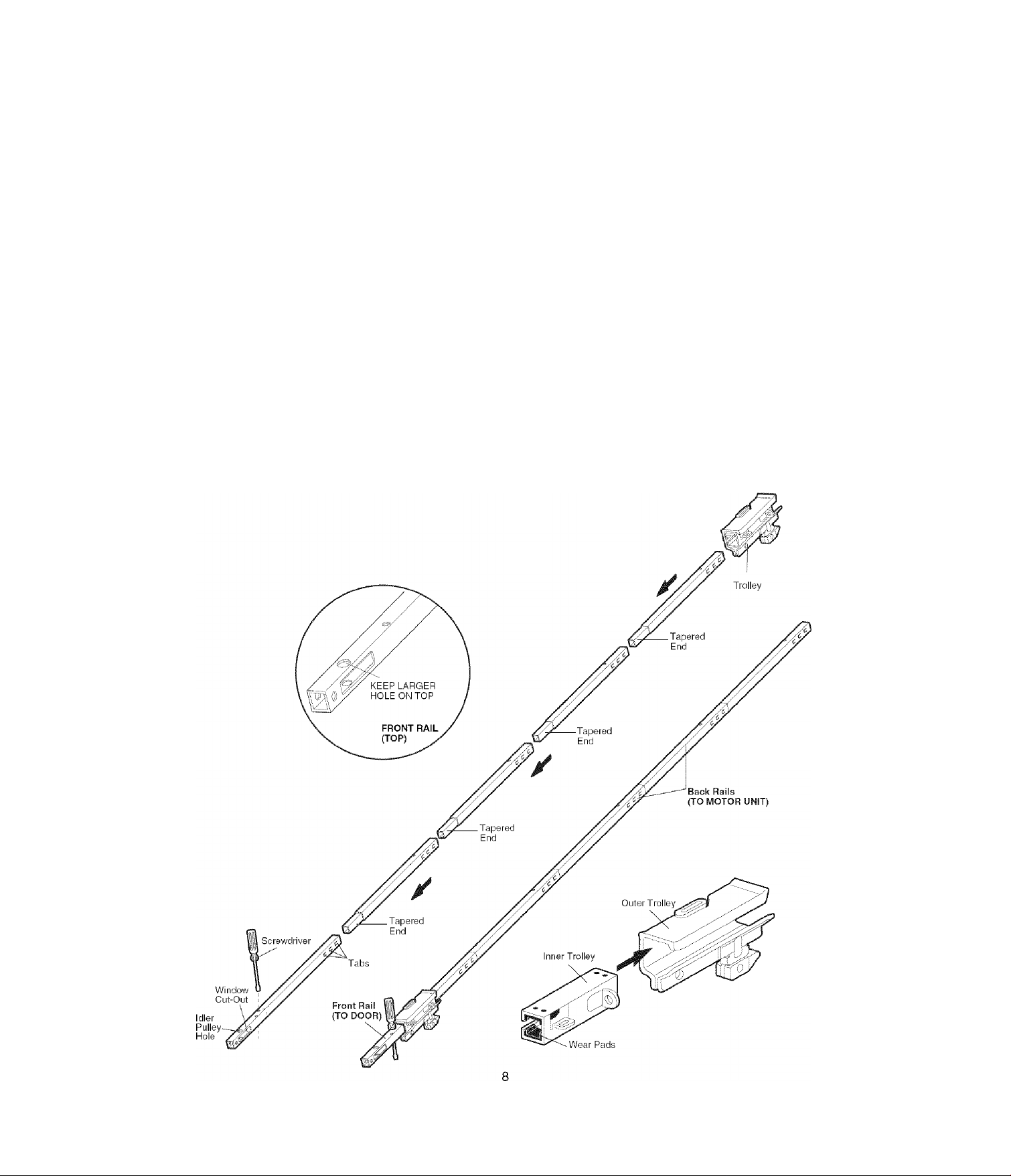
ASSEMBLY STEP 1
Assemble the Rail and Install the Th>//ey
To avoid installation difficulties, do not run the garage door opener until instructed to do so.
CAUTION
To prevent INJURY from pinching, keep hands and fingers
away from the joints while assembling the rail.
The front rail has a cut out “window”at the door end (see
illustration). The hole above this window is larger on
the top of the rail than on the bottom. A smaller hole
3-1/2" (8.9 cm) away is close to the rail edge. Rotate the
back rail so It has a similar hole close to the opposite
edge, about 4-3/4" (12 cm) from the far end.
1. Remove the straight door arm and hanging bracket
packaged inside the front rail and set aside for
Installation Steps 5 and 12. NOTE: To prevent
INJURY while unpacking the rail carefully remove the
straight door arm stored within the rail section.
2. Align the rail sections on a flat surface as shown and
slide the tapered ends into the larger ones. Tabs along
the side will lock into place.
3. Place the motor unit on packing material to protect the
cover, and rest the back end of the rail on top. For
convenience, put a support under the front end of
the rail.
4. As a temporary stop, insert a screwdriver into the hole
10" (25 cm) from the front end of the rail, as shown.
5. Check to be sure there are 4 plastic wear pads inside
the inner trolley. If they became loose during shipping,
check all packing material. Snap them back into
position as shown.
6. Slide the trolley assembly along the rail from the back
end to the screwdriver.
Page 9
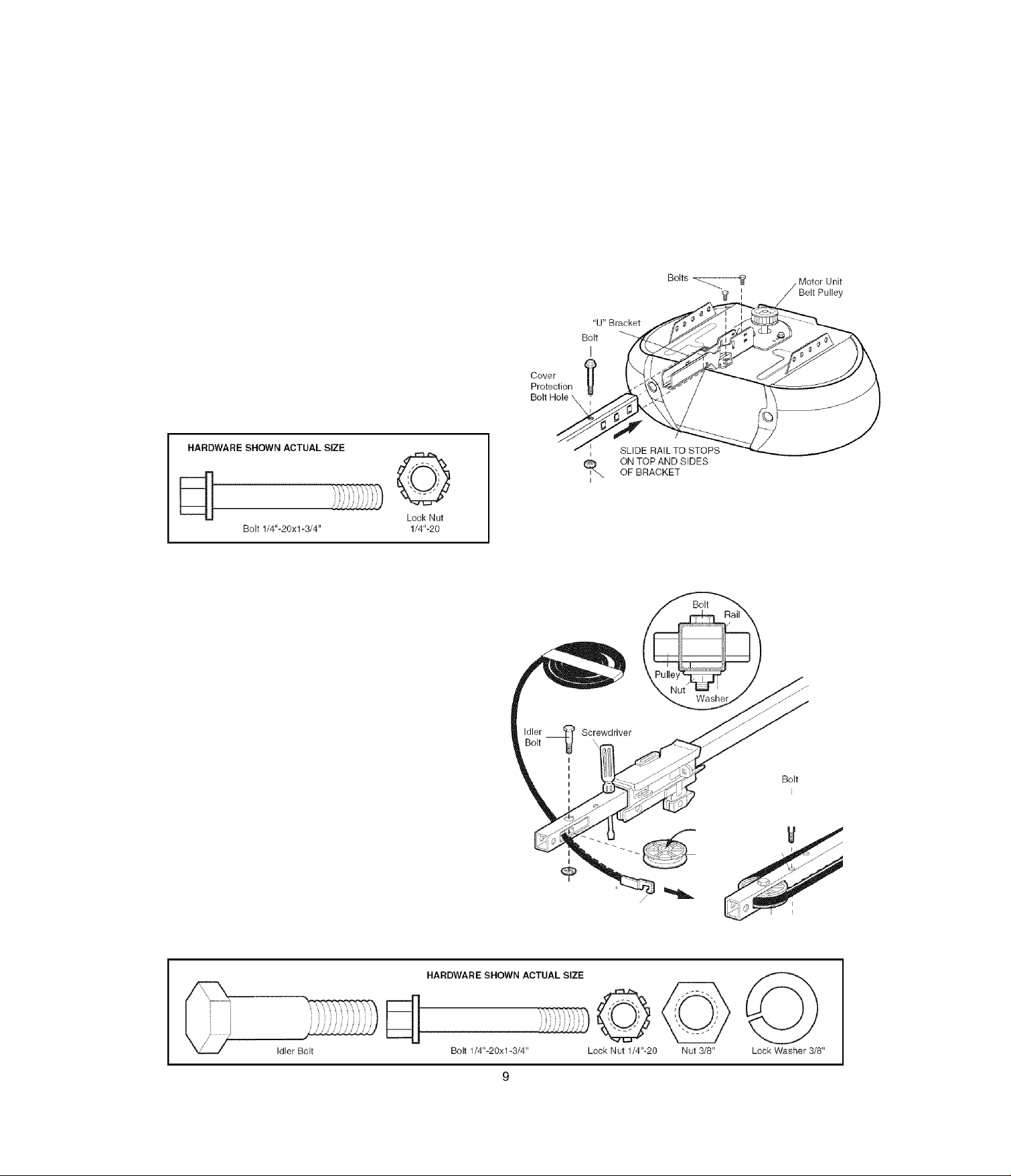
ASSEMBLY STEP 2
Fasten the Rail to the Motor Unit
• Insert a 1/4"-20x1 -3/4 bolt into the cover protection bolt
hole on the back end of the rail as shown. Tighten
securely with a 1/4"-20 lock nut. Do NOT overtighten.
• Remove the two bolts from the top of the motor unit.
• Place the “U" bracket, flat side down, on the motor unit
and align the bracket holes with the bolt holes. Fasten
with the previously removed bolts.
• Align the rail assembly with the top of the motor unit.
Slide the rail end onto the “U” bracket, all the way to
the stops that protrude on the top and sides of the
bracket
CAUTION
To avoid SERIOUS damage to garage door opener, use ONLY
those bolts/fasteners mounted in the top of the opener.
Lock Nut
ASSEMBLY STEP 3
Install the Idler Pulley
• Lay the belt beside the rail, as shown. Grasp the end
with the hooked trolley connector and pass
approximately 12" (30 cm) of belt through the window.
Keep the ribbed side toward the rail, and allow it to
hang until Assembly Step 5.
• Remove the tape from the idler pulley. The inside
center should be pre-greased. If dry, regrease to
ensure proper operation.
• Place the idler pulley into the window as shown.
• Insert the idler bolt from the top through the rail and
pulley. Tighten with a 3/8" lock washer and nut
underneath the rail until the lock washer is
compressed.
• Rotate the pulley to be sure it spins freely.
• Insert a 1/4"-20x1 -3/4 bolt into the trolley stop hole in
the front of the rail as shown. Tighten securely with a
1/4"-20 lock nut.
Lock Washer
3/8" ---
®- Nut 3/8'
I
T rolley
Connector
Trolley
Stop Hole
Grease \
Inside Pulley \
Idler Pulley '
Idler ^ Lock
Pulley I Llut
Page 10
ASSEMBLY STEP 4
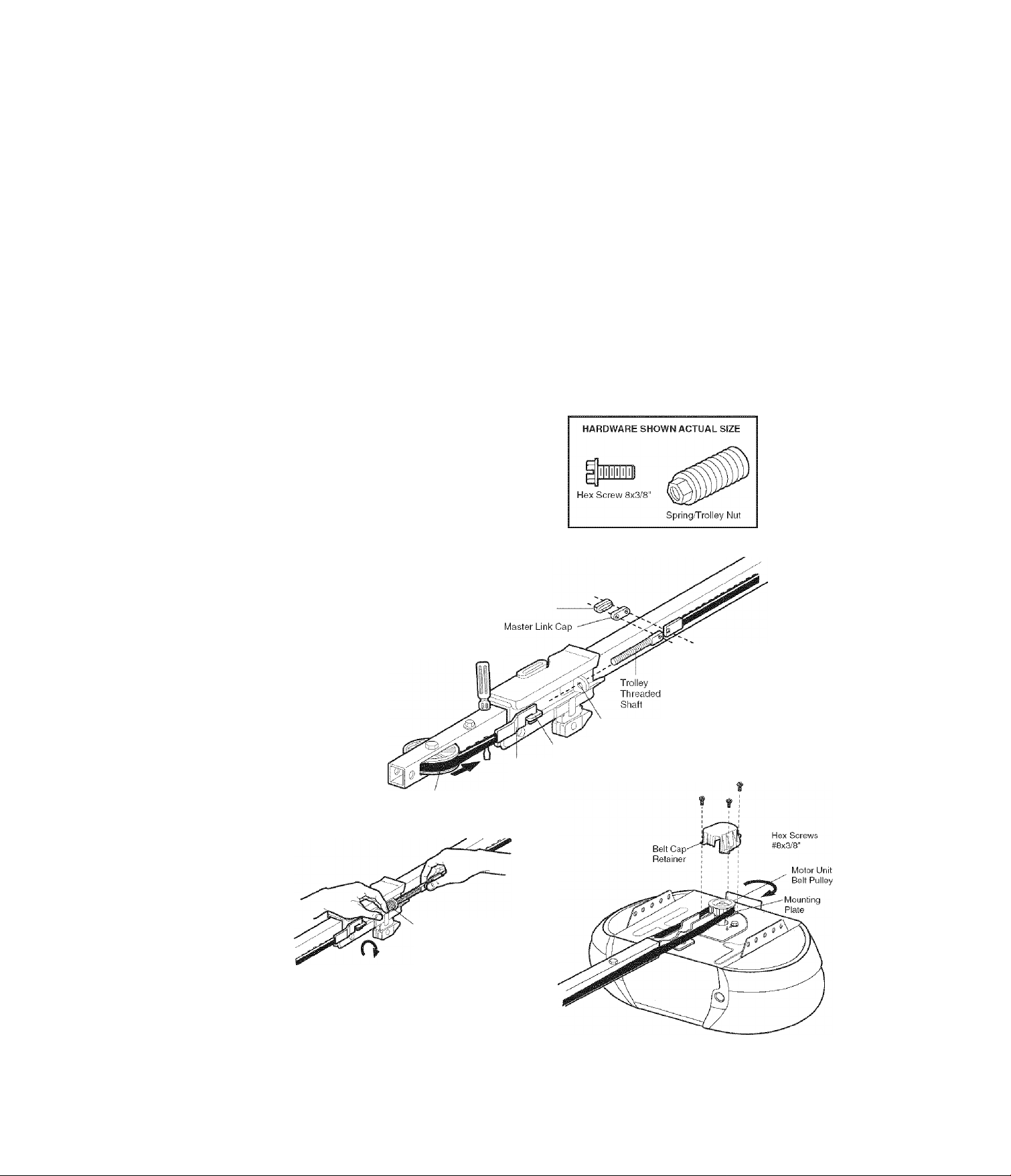
Install the Belt and Attach the Belt Cap Retainer
1. Pull the belt around the idler pulley and toward the
trolley. The ribbed side must contact the puiley.
2. Hook the trolley connector into the retaining siot on
the troiley as shown.
3. With the troiley against the screwdriver, dispense the
remainder of the beit along the rail length toward the
motor unit and around the sprocket. The sprocket
teeth must engage the belt.
4. Check to make sure the belt is not twisted, then
connect it to the flat end of the trolley threaded shaft
with the master link, as illustrated;
• Push pins of master link bar through holes in end of
belt and trolley threaded shaft.
• Push master link cap over pins and past
pin notches.
• Slide clip-on spring over cap and onto pin notches
until both pins are securely locked
in place.
5. Insert the trolley threaded shaft through the hole in
the trolley. Be sure the beit is not twisted, and the
ribbed side faces the rail.
6. Hold the belt at the trolley shaft as you thread the
spring nut by hand onto the shaft until finger tight
against the trolley. Do not use any tools.
7. Remove the screwdriver.
8. Position the belt cap retainer over the motor unit
sprocket as shown and fasten to the mounting plate
with 8x3/8" hex screws provided.
To avoid possible SERIOUS INJURY to fingers from moving
garage door opener:
• ALWAYS keep hand clear of belt pulley while operating
opener.
• Securely attach belt pulley cover BEFORE operating.
Master Link
Clip-On Spring
A WARNING
Pin
Notch
Master
Link Bar
Idler Pulley
Spring Nut
Trolley
Connector
10
Retaining
Slot
Round
Hole
Page 11
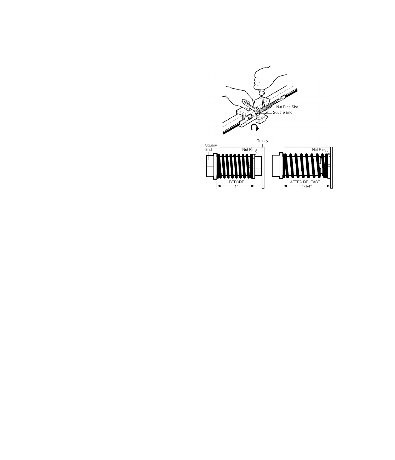
ASSEMBLY STEP 5
Set the Tension
• Insert a screwdriver tip into one of the nut ring slots
and brace it firmly against the trolley.
• Place a 7/16" open end wrench on the square end.
Rotate the nut about 1/4 turn until the spring releases
and snaps the nut ring against the trolley.
This sets the spring to optimum belt tension.
You have now finished assembiing your garage door
opener. Please read the following warnings before
proceeding to the installation section.
INSTALLATION
IMPORTANT INSTALLATION INSTRUCTIONS
A A WARNING
To reduce the risk of SEVERE INJURY or DEATH:
1. READ AND FOLLOW ALL INSTALLATION WARNINGS
AND INSTRUCTIONS.
2. Install garage door opener ONLY on properly balanced
and lubricated garage door. An improperly balanced door
may not reverse when required and could result in
SEVERE INJURY or DEATH.
3. ALL repairs to cables, spring assemblies and other
hardware MUST be made by a trained door systems
technician BEEORE installing opener.
4. Disable ALL locks and remove ALL ropes connected to
garage door BEFORE installing opener to avoid
entanglement.
5. Install garage door opener 7 feet (2.1 m) or more above
floor.
6. Mount emergency release handle 6 feet (1.8 m) above
floor.
7. NEVER connect garage door opener to power source until
instructed to do so.
(2.5 cm)
8. NEVER wear watches, rings or loose clothing while
installing or servicing opener. They could be caught in
garage door or opener mechanisms.
9. Install wall-mounted garage control console:
• within sight of the garage door.
• out of reach of children at minimum height of 5 feet
(1.5 m).
• away from ALL moving parts of the door.
10. Place entrapment warning label on wall next to garage
control console.
11. Place manual release/safety reverse test label in plain
view on inside of garage door.
12. Upon completion of installation, test safety reversal
system. Door MUST reverse on contact with a 1-1/2"
(3.8 cm) high object (or a 2x4 laid flat) on the floor.
13. To avoid SERIOUS PERSONAL INJURY or DEATH from
electrocution, disconnect ALL electric and battery power
BEFORE performing ANY service or maintenance.
(3.18 cm)
11
Page 12
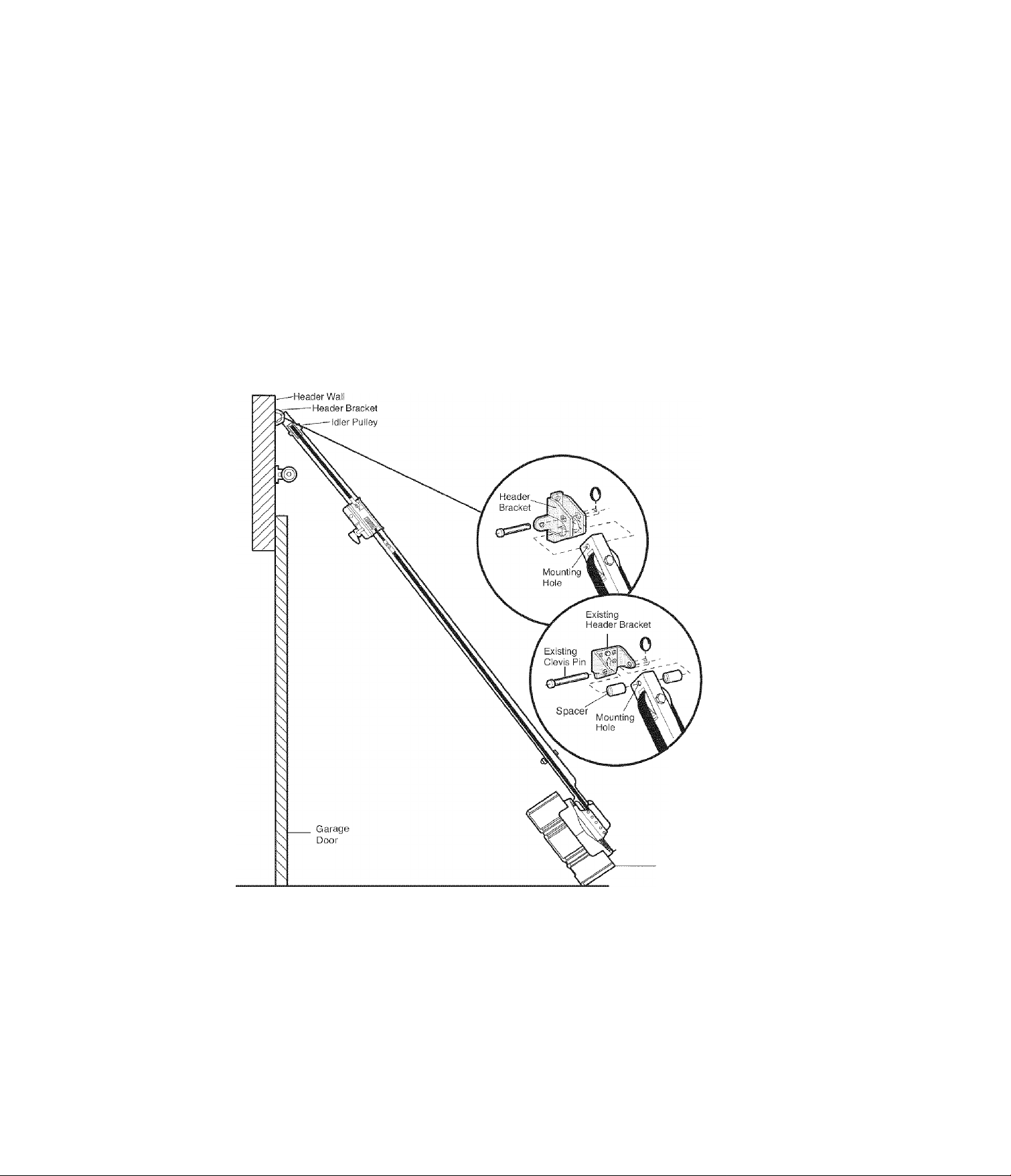
INSTALLATION STEP 1
Determine the Header Bracket Location
WARNING
To prevent possible SERIOUS INJURY or DEATH:
• Header bracket MUST be RIGIDLY fastened to structural
support on header wall or ceiling, otherwise garage door
might not reverse when required. DO NOT install header
bracket over dry wall.
• Concrete anchors MUST be used if mounting header
bracket or 2x4 into masonry.
• NEVER try to loosen, move or adjust garage door, springs,
cables, pulleys, brackets, or their hardware, all of which are
under EXTREME tension.
• ALWAYS call a trained door systems technician if garage
door binds, sticks, or is out of balance. An unbalanced
garage door might not reverse when required.
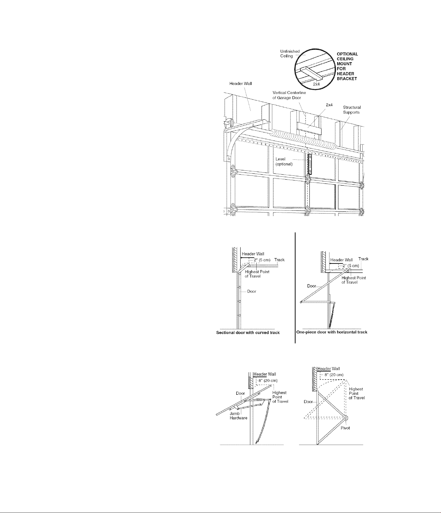
Installation procedures vary according to garage door
types. Follow the instructions which apply to your door.
1 .Close the door and mark the inside vertical centerline
of the garage door.
2. Extend the line onto the header wall above the door.
You can fasten the header bracket within 4 feet
(1.22 m) of the left or right of the door center only
if a torsion spring or center bearing plate is in the
way; or you can attach it to the ceiling (see
page 13) when clearance is minimal. (It may be
mounted on the wall upside down if necessary, to
gain approximately 1/2" (1 cm).)
If you need to install the header bracket on a 2x4
(on wall or ceiling), use lag screws (not provided)
to securely fasten the 2x4 to structural supports as
shown here and on page 13.
3.0pen your door to the highest point of travel as
shown. Draw an intersecting horizontal line on the
header wall above the high point:
• 2" (5 cm) above the high point for sectional door
and one-piece door with track.
• 8" (20 cm) above the high point for one-piece door
without track.
This height will provide travel clearance for the top
edge of the door.
NOTE: If the total number of inches exceeds the
height availabie in your garage, use the maximum
height possibie, or refer to page 13 for ceiiing
insta nation.
One-piece door without track:
jamb hardware
12
One-piece door without track:
pivot hardware
Page 13
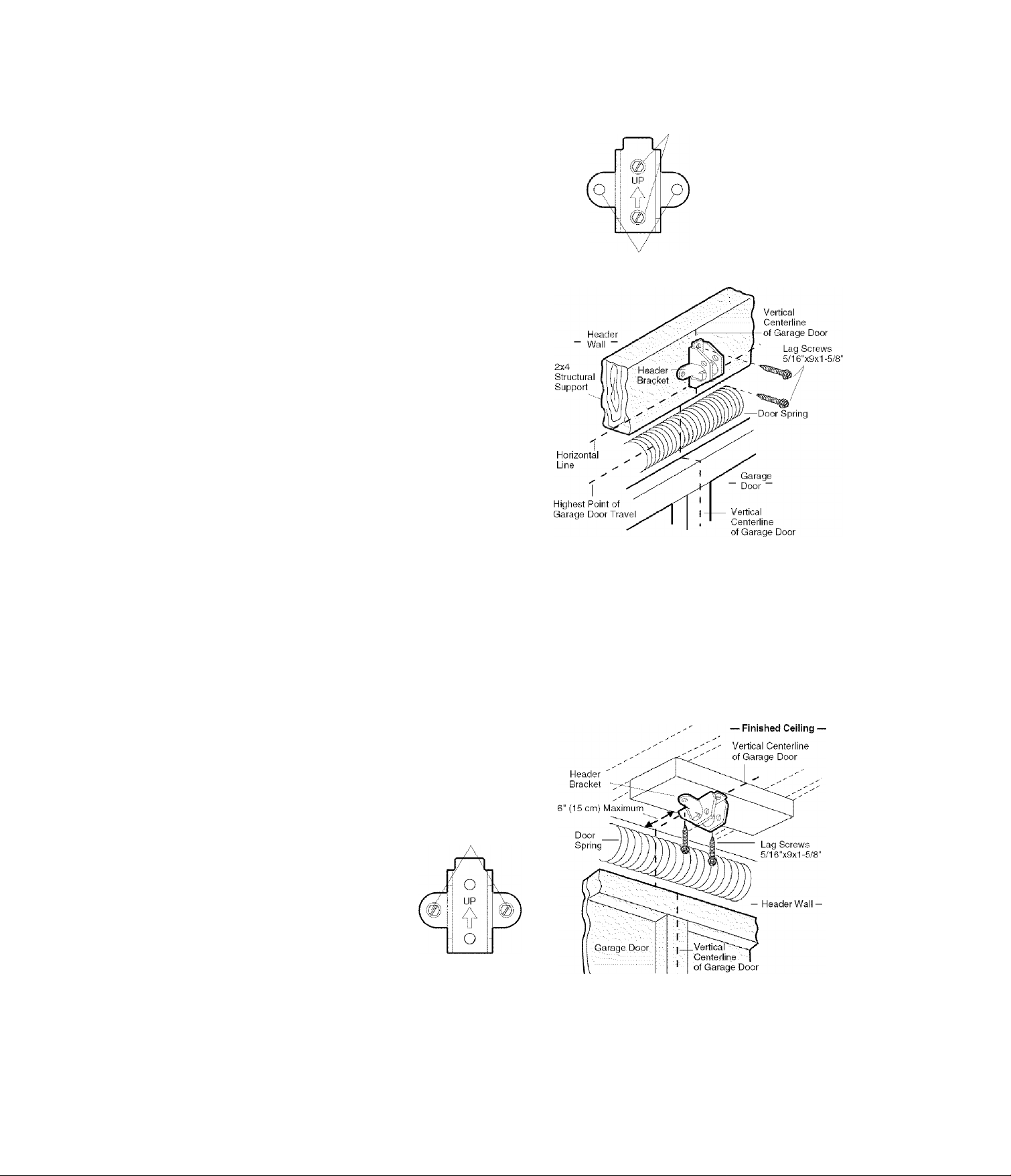
INSTALLATION STEP 2
Install the Header Bracket
You can attach the header bracket either to the wall
above the garage door, or to the ceiling. Follow the
instructions which will work best for your particular
requirements. Do not install the header bracket over
drywall. If installing into masonry, use concrete
anchors (not provided).
WALL HEADER BRACKET INSTALLATION
• Center the bracket on the vertical centerline with the
bottom edge of the bracket on the horizontal line as
shown (with the arrow pointing toward the ceiling).
• Mark the vertical set of bracket holes. Drill 3/16" pilot
holes and fasten the bracket securely to a structural
support with the hardware provided.
HARDWARE SHOWN ACTUAL SIZE
ID>
Lag Screw
5/16"-9x1-5/8"
Wall Mount
Optional
Mounting Holes
CEILING HEADER BRACKET INSTALLATION
• Extend the vertical centerline onto the ceiling as
shown.
• Center the bracket on the vertical mark, no more than
6" (15 cm) from the wall. Make sure the arrow is
pointing away from the wall. The bracket can be
mounted flush against the ceiling when clearance
is minimal.
• Mark the side holes. Drill 3/16" pilot holes and fasten
bracket securely to a structural support with the
hardware provided.
Ceiling Mounting Holes
13
Page 14
INSTALLATION STEP 3
Attach the Rail to the Header Bracket
NOTE: (Optional) With some existing installations, you
may re-use the old header bracket with the two plastic
spacers included in the hardware bag. Place the spacers
inside the bracket on each side of the rail, as illustrated.
• Position the opener on the garage floor below the
header bracket. Use packing material as a protective
base.
NOTE: If the door spring is in the way, you will
need help. Have someone hold the opener securely on
a temporary support to allow the rail to clear the
spring.
• Position the rail bracket against the header bracket.
• Align the bracket holes and join with a clevis pin
as shown.
• Insert a ring fastener to secure.
HARDWARE SHOWN ACTUAL SIZE
O
Clevis Pin 5/16''x1-1/2”
14
O
Ring Fastener
OPTION WITH
SOME EXISTING
INSTALLATIONS
Opener Carton or
Temporary
Support
Page 15
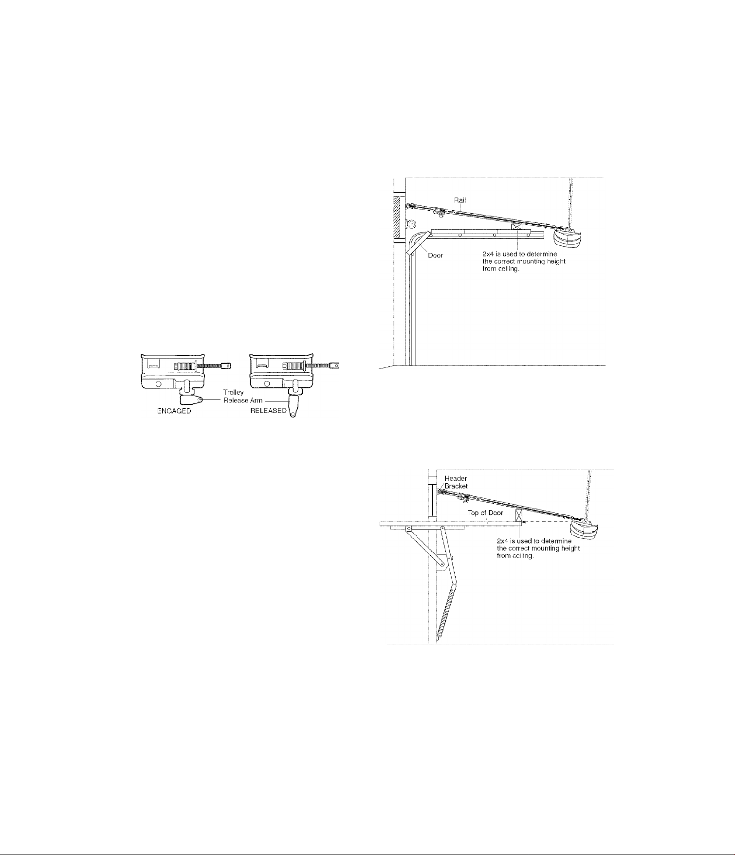
INSTALLATION STEP 4
Position the Opener
Follow instructions which apply to your door type
as illustrated.
SECTIONAL DOOR OR ONE-PIECE DOOR WITH TRACK
A 2x4 laid flat is convenient for setting an ideal
door-to-rail distance.
• Remove foam packaging.
• Raise the opener onto a stepladder. You will need help
at this point if the ladder is not tall enough.
• Open the door all the way and place a 2x4 laid flat on
the top section beneath the rail.
• If the top section or panel hits the trolley when you
raise the door, pull down on the trolley release arm
to disconnect inner and outer sections. Slide the outer
trolley toward the motor unit. The trolley can remain
disconnected until Installation Step 12 is completed.
CAUTION
To prevent damage to garage door, rest garage door opener
rail on 2x4 placed on top section of door.
ONE-PIECE DOORWITHOUTTRACK
A 2x4 on its side is convenient for setting an ideal
door-to-rail distance.
• Remove foam packaging.
• Raise the opener onto a stepladder. You will need help
at this point if the ladder is not tall enough.
• Open the door all the way and place a 2x4 on its side
on the top section of the door beneath the rail.
• The top of the door should be level with the top of the
motor unit. Do not position the opener more than 4"
(10 cm) above this point.
15
Page 16
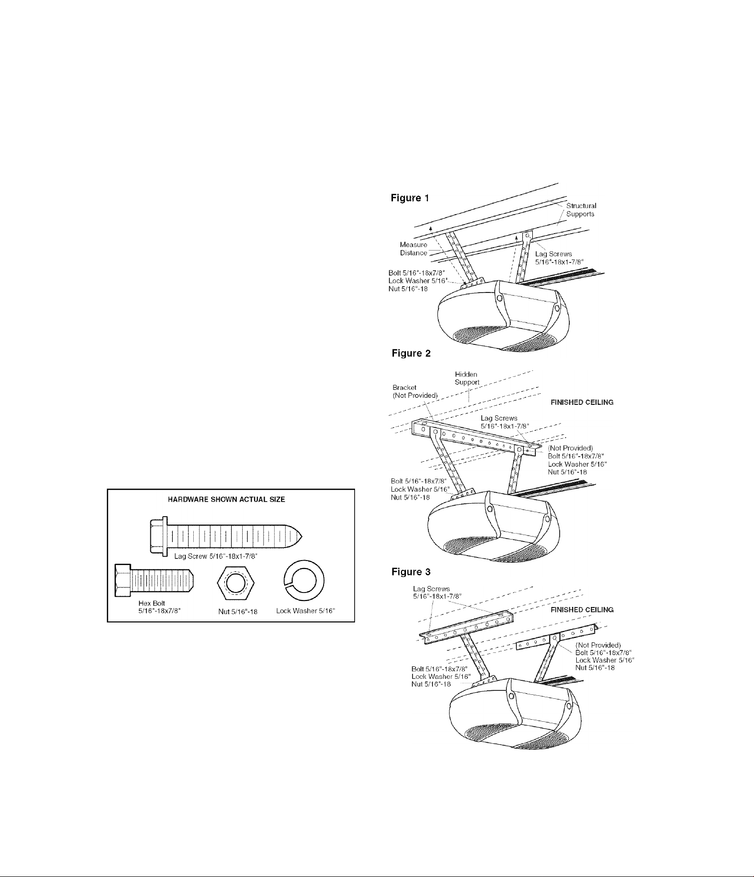
INSTALLATION STEP 5
Hang the Opener
Three representative installations are shown. Yours may
be different. Hanging brackets should be angled
(Figure 1) to provide rigid support. On finished ceilings
(Figures 2 and 3), attach a sturdy metal bracket to
structural supports before installing the opener. This
bracket and fastening hardware are not provided.
1. Measure the distance from each side of the motor unit
to the structural support.
2. Cut both pieces of the hanging bracket to required
lengths.
3. Drill 3/16" pilot holes in the structural supports.
4. Attach one end of each bracket to a support with
5/16"-18x1-7/8” lag screws.
5. Fasten the opener to the hanging brackets with
5/16"-18x7/8" hex bolts, lock washers and nuts.
6. Check to make sure the rail is centered over the door
(or in line with the header bracket if the bracket is not
centered above the door).
7. Remove the 2x4. Cperate the door manually. If the
door hits the rail, raise the header bracket.
NOTE: DO NOT connect power to opener at this time.
A WARNING
To avoid possible SERIOUS INJURY from a falling garage
door opener, fasten it SECURELY to structural supports of
the garage. Concrete anchors MUST be used if installing any
brackets into masonry.
16
Page 17
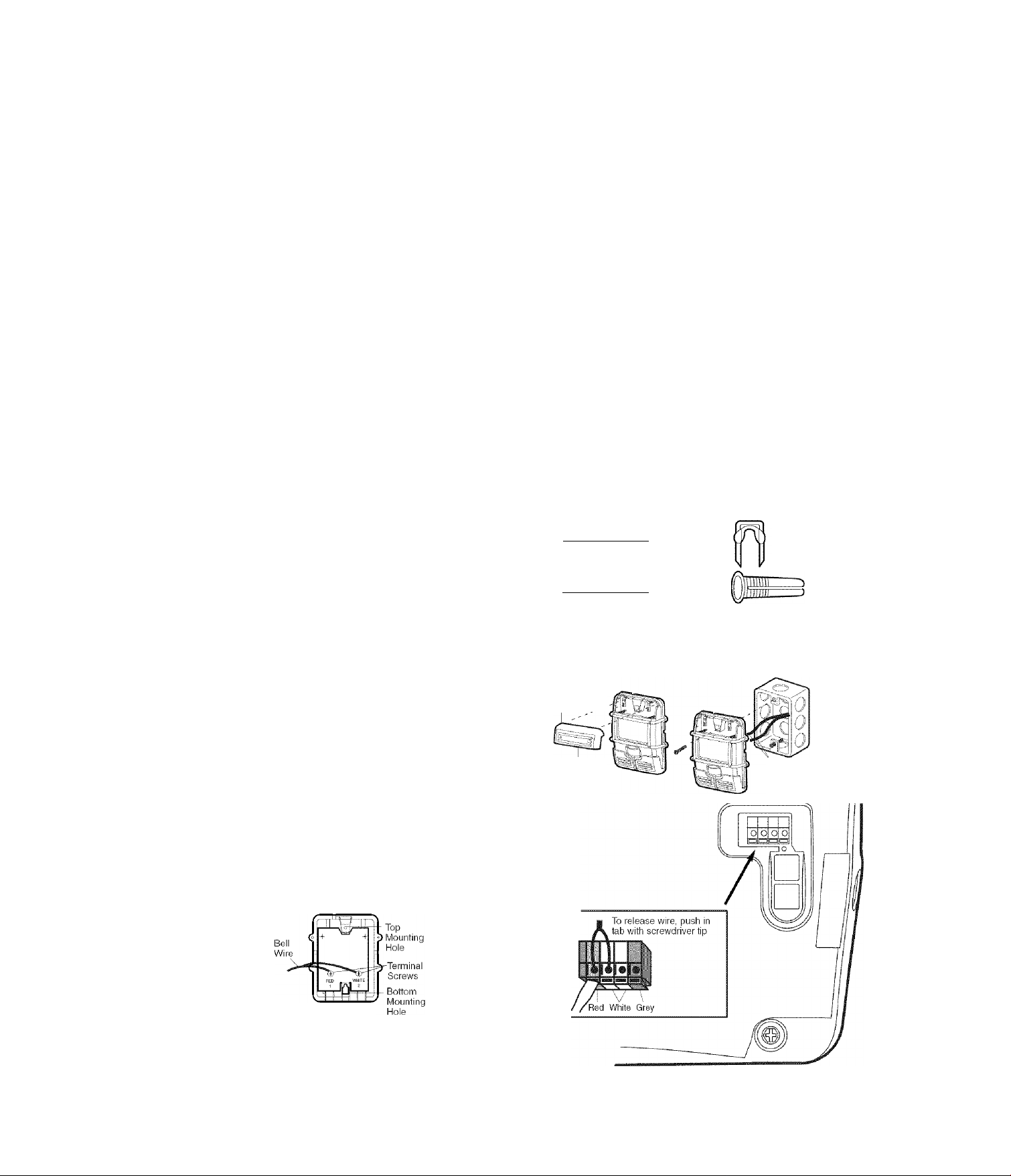
INSTALLATION STEP 6
Install the Control Console
Locate control console within sight of door, at a minimum
height of 5 feet (1.5 m) where small children cannot
reach, away from moving parts of door and door
hardware. If installing into drywall, drill 5/32" holes and
use the anchors provided. For pre-wired installations
(as in new home construction), it may be mounted to a
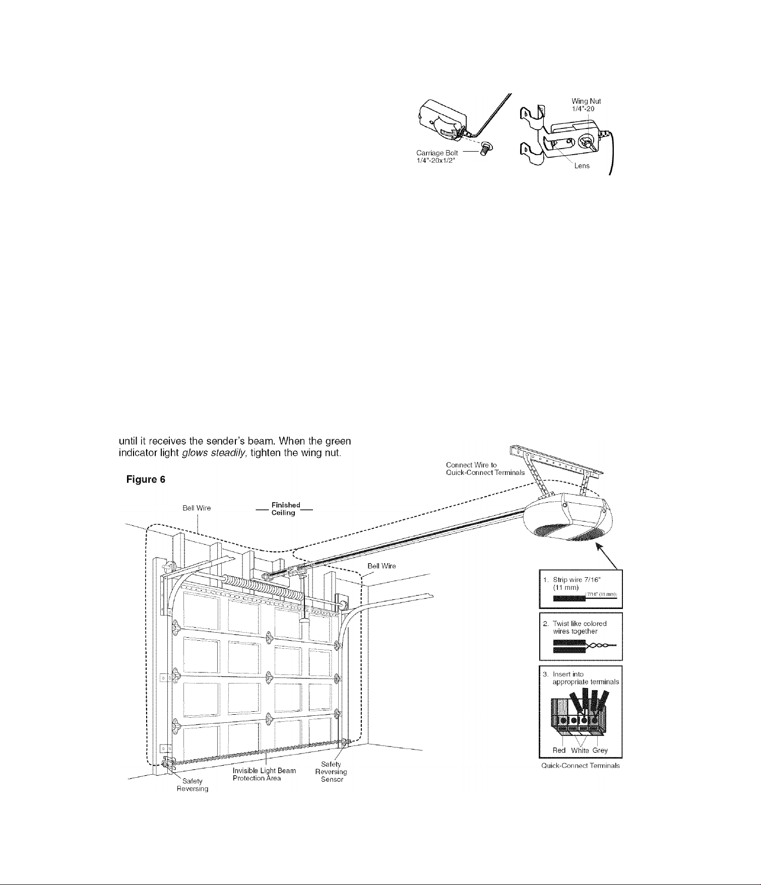
single gang box (Figure 2).
1. Strip 7/16" (11 mm) of insulation from one end of bell
wire and connect to the two screw terminals on back of
control console by color: white wire to 2 and white/red
wire to the 1.
2. Remove cover by gently prying at slot in top of the
cover with a small flat head screwdriver. Fasten with
6ABx1-1/4" self-tapping screws (drywall installation) or
6-32x1" machine screws (into gang box) as follows:
• Install bottom screw, allowing 1/8" (3 mm) to protrude
above wall surface.
• Position bottom of control console on screw head
and slide down to secure. Adjust screw for snug fit.
• Drill and install top screw with care to avoid cracking
plastic housing. Do not overtighten.
• Insert top tabs and snap on cover.
3. (For standard installation only) Run bell wire up wall
and across ceiling to motor unit. Use insulated staples
to secure wire in several places. Do not pierce wire
with a staple, creating a short or open circuit.
4. Strip 7/16" (11 mm) of insulation from end of bell wire.
Connect bell wire to the quick-connect terminals as
follows: white to white and white/red to red.
5. Position the antenna wire as shown.
6. Use tacks or staples to permanently attach entrapment
warning label to wall near control console, and manual
release/safety reverse test label in a prominent
location on inside of garage door.
NOTE: DO NOT connect power and operate opener at
this time. The troliey wili travei to the fuil open position
but wilt not return to the close position until the sensor
beam is connected and properly aligned.
AA WARNING
To prevent possible SERIOUS INJURY or DEATH from
electrocution:
• Disconnect ALL electric and battery power BEFORE
performing ANY service or maintenance.
• Connect ONLY to 24 VOLT low voltage wires.
To prevent possible SERIOUS INJURY or DEATH from a
closing garage door:
• Install control console within sight of garage door, out of
reach of children at a minimum height of 5 feet (1.5 m), and
away from ALL moving parts of door.
• NEVER permit children to operate or play with control
console push buttons or remote controls.
• Activate door ONLY when it can be seen clearly, is properly
adjusted, and there are no obstructions to door travel.
• ALWAYS keep garage door in sight until completely closed.
NEVER permit anyone to cross path of closing garage door.
Outside Keylock Accessory Connections
To opener quick-connect terminals: white to white;
white/red to red.
HARDWARE SHOWN ACTUAL SIZE
|i|i|i|i|i|i|i|i|i|i|i|iT>
a
Screw 6ABx1-1/4‘
Control Panel (std installation)
IIIIIIIIIIIIIIIIIIH1
Screw 6-32x1"
Control Panel (pre-wired)
Figure 1
REMOVE & REPLACE COVER
To Replace
Insert Top
Tabs First
Push Bar Cover
PRE-WIRED INSTALLATION
Insulated
Staples
Drywall Anchors
Figure 2
24 Volt Bell Wire
(BACK VIEW)
Controi Console Connections
Strip wire 7/16“ (11 mm)
C^r'ie" (11 mmi>
17
Page 18
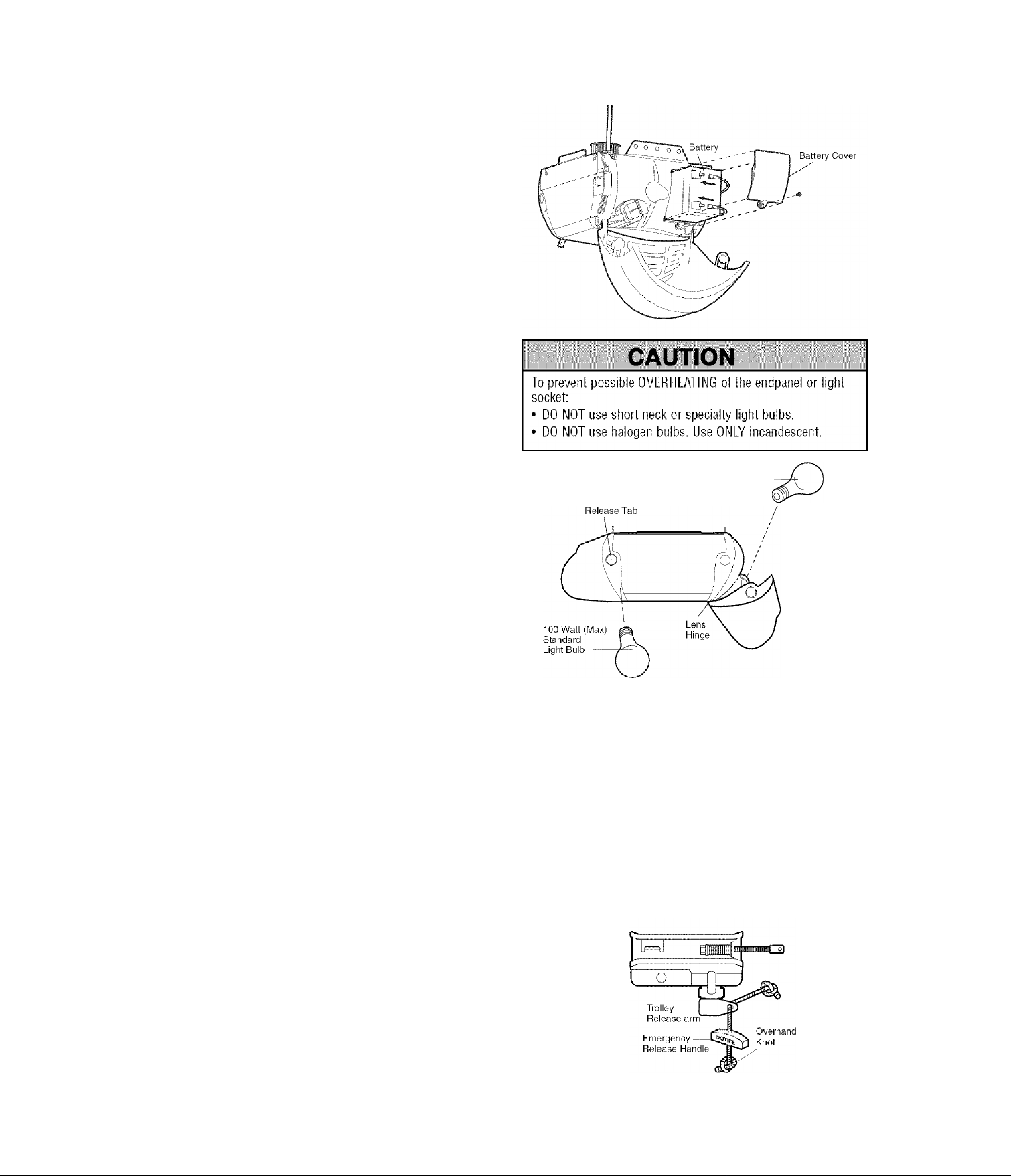
INSTALLATION STEP 7
Install the Battery
• Make sure motor unit is unplugged.
• Using a Phillips head screwdriver, remove the battery
cover on the motor unit.
• Partially insert battery into motor unit with terminals
facing out.
• Connect the red {+) and black (-) wires from motor unit
to corresponding terminals on battery.
• Replace battery cover.
INSTALLATION STEP 8
Install the Lights
• Press the release tabs on both sides of lens. Gently
rotate lens back and downward until the lens hinge is
in the fully open position. Do not remove the lens.
• Install up to a too watt maximum light bulb in each
socket. The lights will turn ON and remain lit for
approximately 4-1/2 minutes when power is
connected. Then the lights will turn OFR
• Reverse the procedure to close the lens.
• If the bulbs burn out prematurely due to vibration,
replace with a Garage Door Opener bulb.
NOTE: Use only standard light bulbs. The use of short
neck or speciality light bulbs may overheat the endpanel
or light socket.
100 Watt (Max) —
Standard Light Bulb
INSTALLATION STEP 9
Attach the Emergency Release Rope and Handle
• Thread one end of the rope through the hole in the top
of the red handle so “NOTICE” reads right side up
as shown. Secure with an overhand knot at least
1" (2.5 cm) from the end of the rope to prevent
slipping.
• Thread the other end of the rope through the hole in
the release arm of the outer trolley.
• Adjust rope length so the handle is 6 feet (1.83 m)
above the floor. Ensure that the rope and handle clear
the tops of all vehicles to avoid entanglement. Secure
with an overhand knot.
NOTE: If it is necessary to cut the rope, heat seal the cut
end with a match or lighter to prevent unraveling.
A WARNING
To prevent possible SERIOUS INJURY or DEATH from a
falling garage door:
• If possible, use emergency release handle to disengage
trolley ONLY when garage door is CLOSED. Weak or
broken springs or unbalanced door could result in an open
door falling rapidly and/or unexpectedly.
• NEVER use emergency release handle unless garage
doorway is clear of persons and obstructions.
• NEVER use handle to pull door open or closed. If rope knot
becomes untied, you could fall.
Trolley
18
Page 19
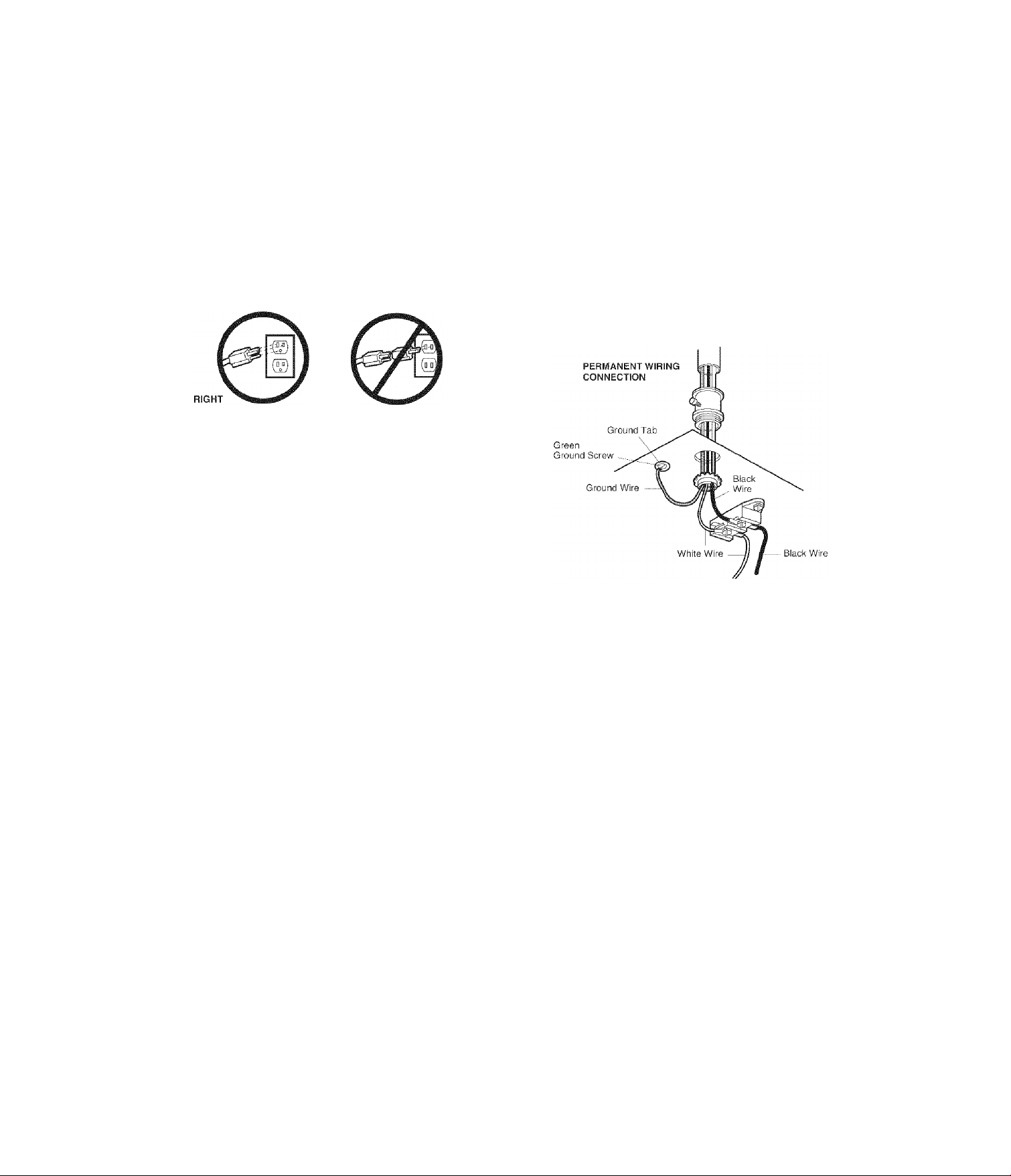
INSTALLATION STEP 10
Electrical Requirements
To avoid installation difficulties, do not run the opener at this time.
To reduce the risk of electric shock, your garage door
opener has a grounding type plug with a third grounding
pin. This plug will only fit into a grounding type outlet. If
the plug doesn’t fit into the outlet you have, contact a
qualified electrician to install the proper outlet.
WRONG
If permanent wiring is required by your local code, refer to the following procedure.
To make a permanent connection through the 7/8" (2 cm)
hole in the top of the motor unit:
• Remove the motor unit cover screws and set the cover
aside.
• Remove the attached 3-prong cord.
• Connect the black (line) wire to the screw on the brass
terminal; the white (neutral) wire to the screw on the
silver terminal; and the ground wire to the green
ground screw. The opener must be grounded.
• Reinstall the cover.
To avoid installation difficulties, do not run the
opener at this time.
A WARNING
To prevent possible SERIOUS INJURY or DEATH from
electrocution or fire:
• Disconnect ALL electric and battery power BEFORE
performing ANY service or maintenance.
• Garage door installation and wiring MUST be in compliance
with ALL local electrical and building codes.
• NEVER use an extension cord, 2-wire adapter, or change
plug in any way to make it fit outlet. Be sure the opener
is grounded.
19
Page 20
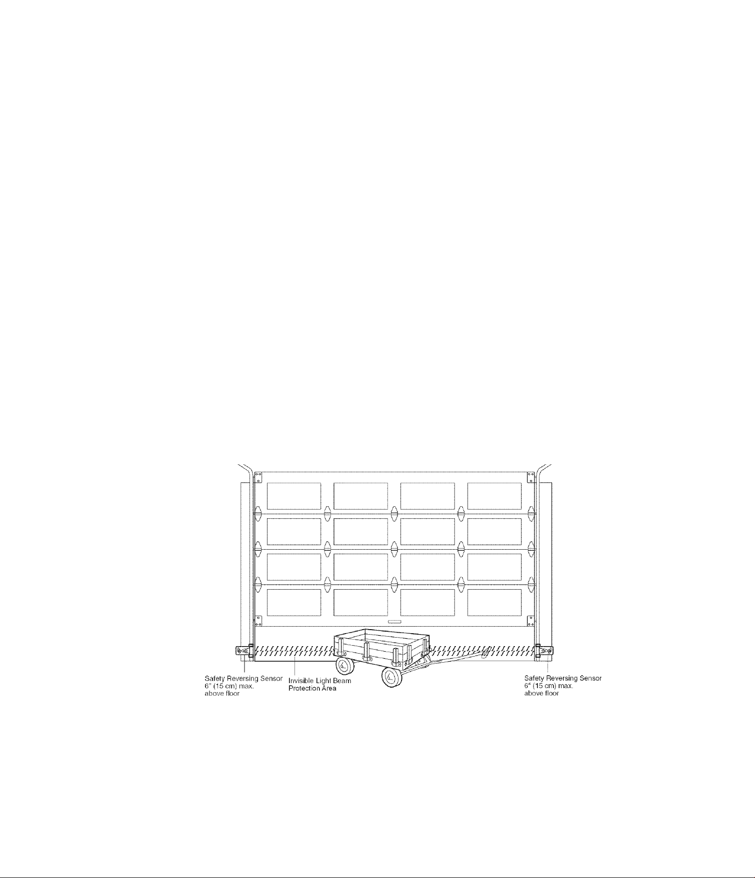
INSTALLATION STEP 11
Install The Protector System^
(Safety Sensors)
The safety reversing sensor must be connected and
aligned correctly before the garage door opener will
move in the down direction.
IMPORTANT INFORMATION ABOUT THE SAFETY REVERSING SENSOR
When properly connected and aligned, the sensor will
detect an obstacle in the path of its electronic beam. The
sending eye (with an amber indicator light) transmits an
invisible light beam to the receiving eye (with a green
indicator light). If an obstruction breaks the light beam
while the door is closing, the door will stop and reverse
to full open position, and the opener lights will flash
10 times.
The units must be installed inside the garage so that the
sending and receiving eyes face each other across the
door, no more than 6" (15 cm) above the floor. Either can
be installed on the left or right of the door as long as the
sun never shines directly into the receiving eye lens.
The mounting brackets are designed to clip onto the
track of sectional garage doors without additional
hardware.
ik WARNING
Be sure power is NOT connected to the garage door opener
BEFORE installing the safety reversing sensor.
To prevent SERIOUS INJURY or DEATH from a closing
garage door:
• Correctly connect and align the safety reversing sensor.
This required safety device MUST NOT be disabled.
• Install tbe safety reversing sensor so beam is NO HIGHER
than 6" (15 cm) above garage floor.
If it is necessary to mount the units on the wall, the
brackets must be securely fastened to a solid surface
such as the wall framing. Extension brackets (see
accessories) are available if needed. If installing in
masonry construction, add a piece of wood at each
location to avoid drilling extra holes in masonry if
repositioning is necessary.
The invisible light beam path must be unobstructed. No
part of the garage door (or door tracks, springs, hinges,
rollers or other hardware) may interrupt the beam while
the door is closing.
Facing the door from inside the garage
20
Page 21
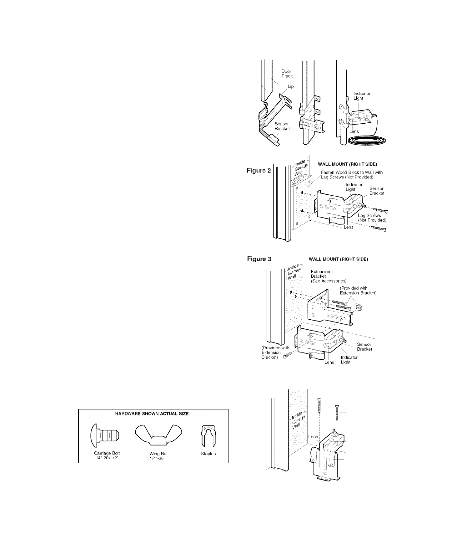
INSTALLING THE BRACKETS
Be sure power to the opener is disconnected. Install
and align the brackets so the sensors will face each
other across the garage door, with the beam no higher
than 6" (15 cm) above the floor. They may be installed in
one of three ways, as follows.
Garage door track installation (preferred):
• Slip the curved arms over the rounded edge of each
door track, with the curved arms facing the door. Snap
into place against the side of the track. It should lie
flush, with the lip hugging the back edge of the track
(Figure 1).
If your door track will not support the bracket securely,
wall installation is recommended.
Wall installation (Figures 2 and 3):
• Place the bracket against the wall with curved arms
facing the door. Be sure there is enough clearance for
the sensor beam to be unobstructed.
• If additional depth is needed, an extension bracket
(see Accessories) or wood blocks can be used.
• Use bracket mounting holes as a template to locate
and drill (2) 3/16" diameter pilot holes on the wall at
each side of the door, no higher than 6" (15 cm) above
the floor.
• Attach brackets to wall with lag screws (not provided).
• If using extension brackets or wood blocks, adjust right
and left assemblies to the same distance out from the
mounting surface. Make sure all door hardware
obstructions are cleared.
Floor installation (Figure 4):
• Use wood blocks or extension brackets (see
Accessories) to elevate sensor brackets so the lenses
will be no higher than 6" (15 cm) above the floor.
• Carefully measure and place right and left assemblies
at the same distance out from the wall. Be sure all
door hardware obstructions are cleared.
• Fasten to the floor with concrete anchors as shown.
Figure
1 door track mount (right side)
21
Figure 4
floor mount (RIGHT SIDE)
Concrete Anchors
(Not Provided)
Indicator
Light
- Sensor
Bracket
Page 22
MOUNTING AND WIRING THE SAFETY REVERSING SENSORS
• Slide a 1/4"-20x1/2" carriage bolt head Into the slot on
each sensor. Use wing nuts to fasten sensors to
brackets, with lenses pointing toward each other
across the door. Be sure the lens is not obstructed by
a bracket extension (Figure 5).
• Finger tighten the wing nuts.
• Run the wires from both sensors to the opener. Use
insulated staples to secure wire to wall and ceiling.
• Strip 7/16" (11 mm) of insulation from each set of
wires. Separate white and white/black wires sufficiently
to connect to the opener guick-connect terminals. Twist
like colored wires together. Insert wires into
quick-connect holes: white to white and white/black
to grey (Figure 6).
ALIGNING THE SAFETY REVERSING SENSORS
• Plug in the opener. The indicator lights in both the
sending and receiving eyes m\\ glow steadily W wiring
connections and alignment are correct.
The sending eye amber indicator light will glow
regardless of alignment or obstruction. If the green
indicator light in the receiving eye is off, dim, or flickering
(and the invisible light beam path is not obstructed),
alignment is required.
• Loosen the sending eye wing nut and readjust, aiming
directly at the receiving eye. Lock in place.
• Loosen the receiving eye wing nut and adjust sensor
Figure 5
TROUBLESHOOTING THE SAFETY REVERSING SENSORS
1. If the sending eye indicator light does not glow steadily
after installation, check for:
• Electric power to the opener.
• A short in the white or white/black wires. These can
occur at staples, or at opener connections.
• Incorrect wiring between sensors and opener.
• A broken wire.
2. If the sending eye indicator light glows steadily but the
receiving eye indicator light doesn't:
• Check alignment.
• Check for an open wire to the receiving eye.
3. If the receiving eye indicator light is dim, realign either
sensor.
NOTE: When the invisible beam path is obstructed or
misaligned while the door is closing, the door will reverse.
If the door is already open, it will not close.
The opener lights will blink 10 times. See page 20.
Sensor
22
Page 23
INSTALLATION STEP 12
Fasten the Door Bracket
Follow instructions which apply to your door type
as illustrated below or on the following page.
A horizontal reinforcement brace should be long
enough to be secured to two vertical supports. A
vertical reinforcement brace should cover the height
of the top panel.
The illustration shows one piece of angle iron as the
horizontal brace. For the vertical brace, two pieces of
angle iron are used to create a U-shaped support
(Figure 1). The best solution is to check with your
garage door manufacturer for an opener installation door
reinforcement kit.
NOTE: Many vertical brace installations provide for direct
attachment of the clevis pin and door arm. In this case
you will not need the door bracket; proceed to
Installation Step 13.
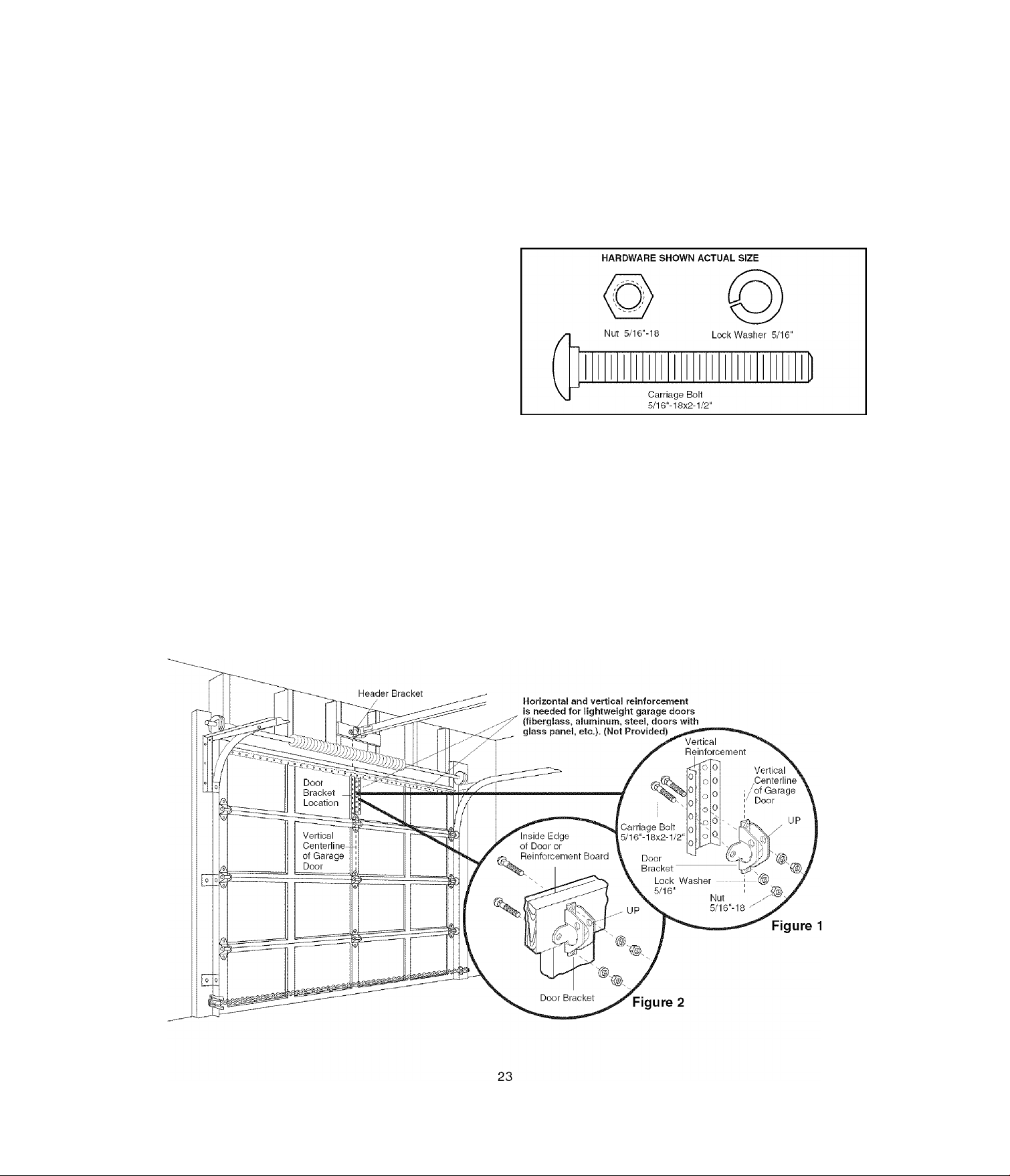
SECTIONAL DOORS
1. Center the door bracket on the previously marked
vertical centerline used for the header bracket
installation. Note correct UP placement, as stamped
inside the bracket (Figure 2).
2. Position the bracket on the face of the door within the
following limits:
• The top edge of the bracket 2"-4" (5-10 cm) below
the top edge of the door.
• The top edge of the bracket directly below any
structural support across the top of the door.
CAUTION
Fiberglass, aluminum or lightweight steel garage doors
WILL REQUIRE
bracket. Contact your door manufacturer for
reinforcement kit.
• Mark and drill 5/16" left and right fastening holes.
Secure the bracket as shown in Figure 1 if there is
vertical reinforcement.
If your installation doesn't require vertical reinforcement
but does need top and bottom fastening holes for the
door bracket, fasten as shown in Figure 2.
reinforcement BEFORE installation of door
Page 24
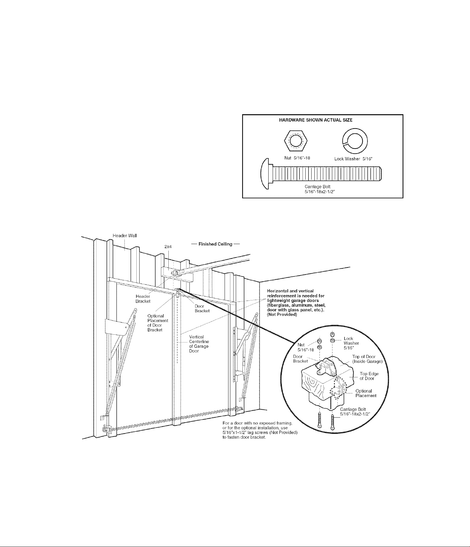
ONE-PIECE DOORS
Please read and comply with the warnings and
reinforcement instructions on the previous page. They
apply to one-piece doors also.
• Center the door bracket on the top of the door, in line
with the header bracket as shown. Mark either the left
and right, or the top and bottom holes.
• Drill 5/16" pilot holes and fasten the bracket with
hardware supplied.
If the door has no exposed framing, drill 3/16" pilot holes
and fasten the bracket with 5/16”x1-1/2" lag screws
(not provided) to the top of the door.
NOTE: The door bracket may be installed on the top
edge of the door If required for your instailation. (Refer to
the dotted line optional placement drawing.) Drili 3/16"
pilot holes and substitute 5/16"x1-1/2" lag screws (not
provided) to fasten the bracket to the door.
24
Page 25

INSTALLATION STEP 13
Connect Door Arm to Trolley
Follow Instructions which apply to your door type as
illustrated below and on the following page.
SECTIONAL DOORS ONLY
Make sure garage door is fully closed. Pull the
emergency release handle to disconnect the outer trolley
from the inner trolley. Slide the outer trolley back (away
from the pulley) about 8" (20 cm) (Figures 1,2 and 3).
Figure 1:
• Fasten straight door arm section to outer trolley with
the 5/16"x1'' clevis pin. Secure the connection with a
ring fastener.
• Fasten curved section to the door bracket in the same
way, using the 5/16"x1-1/4" clevis pin.
Figure 2:
• Bring arm sections together. Find two pairs of holes
that line up and join sections. Select holes as far apart
as possible to increase door arm rigidity.
Figure 3, Hoie alignment alternative:
• If holes in curved arm are above holes in straight arm,
disconnect straight arm. Cut about 6" (15 cm) from the
solid end. Reconnect to trolley with cut end down
as shown.
• Bring arm sections together.
• Find two pairs of holes that line up and join with bolts,
lock washers and nuts.
Pull the emergency release handle toward the opener at
a 45° angle so that the trolley release arm is horizontal.
Proceed to Adjustment Step 1, page 27. Trolley will
re-engage automatically when opener is operated.
Pulley
Figure 1
Pulley
Figure 2
25
Pulley
Figure 3
Page 26

ALL ONE-PIECE DOORS
1. Assemble the Door Arm:
• Fasten the straight and curved door arm sections
together to the longest possible length (with a 2 or 3
hole overlap).
• Make sure the garage door is fully closed. Connect
the straight door arm section to the door bracket with
the 5/16"x1-1/4" clevis pin.
• Secure with a ring fastener.
• Pull the emergency release handle, disconnecting the
outer trolley from the inner trolley by pulling straight
down on the emergency release handle and sliding
the outer trolley back toward the motor unit.
• Connect the curved door arm section to the trolley
using the 5/16"x1-1/4" clevis pin and ring fastener.
NOTE: Adjusting the limits on the following page:
• The trolley will automatically connect If not, review
the trolley lockout feature on page 32.
• When setting the up limit on the following page, the
door should not have a “backward” slant when fully
open as Illustrated below. A slight backward slant will
cause unnecessary bucking and/or jerking operation
as the door is being opened or closed from the fully
open position.
Door
26
Page 27

ADJUSTMENT STEP 1
Program the Travel Limits
Travel limits regulate the points at which the door
will stop when moving up or down. Follow the steps
below to set the limits.
A WARNING
Without a properly installed safety reversal system, persons
(particularly small children) could be SERIOUSLY INJURED
or KILLED by a closing garage door.
• Incorrect adjustment of garage door travel limits will
interfere with proper operation of safety reversal system.
• NEVER use force adjustments to compensate for a binding
or sticking garage door.
• After ANY adjustments are made, the safety reversal system
MUST be tested. Door MUST reverse on contact with 1-1/2"
(3.8 cm) high object (or 2x4 laid flat) on floor.
CAUTION
To program the travel limits:
Adjust the position of the door by using the black and
purple buttons. Black moves the door UP (open) and
purple moves the door DOWN (close).
1. Setting the UP position: Press and hold the black
button until the yellow indicator light starts flashing
slowly then release.
2. Push and hold the black button until the door reaches
the desired UP (open) position (Figure 2).
NOTE: Check to be sure the door opens high enough for
your vehicle.
3. Push the remote control or door control (Figure 3).
This sets the UP (open) limit and begins closing the
door.
NOTE: Excessive movement of the motor unit will cause
premature wear. See Troubleshooting section.
4. Immediately when the door begins to move down,
press and release either the black or purple button.
This will stop the door.
5. Setting the DOWN position: Push and hold the
purple button until the door reaches the desired
DOWN (closed) position (Figure 4).
6. Once the door is closed, if there appears to have too
much pressure on the door, you may toggle the door
back and forth using the black and purple buttons to
reach the desired closed position.
7. Push the remote control or the door control (Figure 3).
This sets the DOWN (close) limit and should bring the
door to the open position.
• If the opener is not stopping exactly where you
would like it, repeat steps 1 through 8 and program
the limits again.
• When the unit stops in both the desired up (open)
and down (close) positions, proceed to
Adjustment Step 2, Setting the Force.
To prevent damage to vehicles, be sure fully open door
provides adequate clearance.
Figure 3
27
Page 28

ADJUSTMENT STEP 2
Setting the Force
The force setting button is located on the left panel
of the motor unit. The force setting measures the
amount of force required to open and close the door.
1. Locate the purple button on the left panel of the motor
unit (Figure 1).
2. Push the purple button twice to enter the opener Into
Force Adjustment Mode (Figure 2). The LED (Indicator
Light) will flash quickly.
3. Push the remote control or control console (Figure 3).
The door will travel to the DOWN (close) position.
Push the remote control or control console again, the
door will travel to the UP (open) position. Push the
remote control or control console a third time to send
the door to the DOWN (close) position.
The LED (Indicator Light) will stop flashing when the
force has been learned.
The opener has learned the forces required to open and
close your door.
The door must travel through a complete cycle, UP and
DOWN, in order for the force to be set properly. If the
opener cannot open and close your door fully, inspect
your door to insure that it is balanced properly and is not
sticking or binding. See page 3, “Preparing your
garage door.”
A WARNING
Without a properly installed safety reversal system, persons
(particularly small children) could be SERIOUSLY INJURED
or KILLED by a closing garage door.
• Too much force on garage door will interfere with proper
operation of safety reversal system.
• NEVER use force adjustments to compensate for a binding
or sticking garage door.
• After ANY adjustments are made, the safety reversal system
MUST be tested. Door MUST reverse on contact with 1-1/2"
(3.8 cm) high object (or 2x4 laid flat) on floor.
Figure 1
28
Page 29

ADJUSTMENT STEP 3
Test the Safety Reversal System
TEST
• With the door fully open, place a 1 -1/2" (3.8 cm) board
(or a 2x4 laid flat) on the floor, centered under the
garage door.
• Operate the door in the down direction. The door must
reverse on striking the obstruction.
ADJUST
• If the door stops on the obstruction, it is not traveling
far enough in the down direction. Complete Adjustment
Steps 1 and 2.
NOTE: On a sectional door, make sure limit
adjustments do not force the door arm beyond a
straight up and down position. See Figure 3, page 25.
• Repeat the test.
• When the door reverses on the 1 -1/2" (3.8 cm) board
(or 2x4 laid flat), remove the obstruction and run the
opener through 3 or 4 complete travel cycles to test
adjustment.
• If the unit continues to fail the Safety Reverse Test, call
for a trained door systems technician.
ik WARNING
Without a properly installed safety reversal system, persons
(particularly small children) could be SERIOUSLY INJURED
or KILLED by a closing garage door.
• Safety reversal system MUST be tested every month.
• After ANY adjustments are made, the safety reversal
system MUST be tested. Door MUST reverse on contact
with 1-1/2" high (3.8 cm) object (or 2x4 laid flat) on
the floor.
IMPORTANT SAFETY CHECK:
Test the Safety Reverse System after;
• Each adjustment of door arm length, limits, or force
controls.
• Any repair to or adjustment of the garage door
(including springs and hardware).
• Any repair to or buckling of fhe garage floor.
• Any repair fo or adjusfment of the opener.
ADJUSTMENT STEP 4
Test The Protector System®
(Safety Sensors)
• Press the remote control push button to open the door.
• Place the opener carton in the path of the door.
• Press the remote control push button to close the door.
The door will not move more than an inch (2.5 cm),
and the opener lights will flash.
The garage door opener will not close from a remote if
the indicator light in either sensor is off (alerting you to
the fact that the sensor is misaligned or obstructed).
If the opener closes the door when the safety
reversing sensor is obstructed (and the sensors are
no more than 6" (15 cm) above the floor), call for a
trained door systems technician.
29
Page 30

OPERATION
IMPORTANT SAFETY INSTRUCTIONS
A ik WARNING
To reduce the risk of SEVERE INJURY or DEATH:
1. READ AND FOLLOW ALL WARNINGS AND INSTRUCTIONS.
2. ALWAYS keep remote controls out of reach of children.
NEVER permit children to operate or play with garage
control console push buttons or remote controls.
3. ONLY activate garage door when it can be seen clearly, it is
properly adjusted, and there are no obstructions to door
travel.
4. ALWAYS keep garage door in sight until completely closed.
NO ONE SHOULD CROSS THE PATH OE THE MOVING
DOOR.
5. NO ONE SHOULD GO UNDER A STOPPED, PARTIALLY
OPEN DOOR.
6. If possible, use emergency release handle to disengage
trolley ONLY when garage door is CLOSED. Weak or broken
springs or unbalanced door could result in an open door
falling rapidly and/or unexpectedly.
7. NEVER use emergency release handle unless garage
doorway is clear of persons and obstructions.
8. NEVER use handle to pull garage door open or closed. If
rope knot becomes untied, you could fall.
9. If one control (force or travel limits) is adjusted, the other
control may also need adjustment.
10. After ANY adjustments are made, the safety reversal
system MUST be tested.
11. Safety reversal system MUST be tested every month.
Garage door MUST reverse on contact with 1-1/2" high
(3.8 cm) high object (or a 2x4 laid flat) on the floor.
12. ALWAYS KEEP GARAGE DOOR PROPERLY BALANCED
(see page 3). An improperly balanced door may not
reverse when required and could result in SEVERE INJURY
or DEATH.
13. ALL repairs to cables, spring assemblies and other
hardware, all of which are under EXTREME tension, MUST
be made by a trained door systems technician.
14. To avoid SERIOUS PERSONAL INJURY or DEATH from
electrocution, disconnect ALL electric and battery power
BEFORE performing ANY service or maintenance.
15 SAVE THESE INSTRUCTIONS.
Using Your Garage Door Opener
Your Security+® opener and hand-held remote control
have been factory-set to a matching code which changes
with each use, randomly accessing over 100 billion new
codes. Your opener will operate with up to ten Security+®
remote controls, one Security+® Keyless Entry System,
and one accessory wall control. If you purchase a new
remote, or if you wish to deactivate any remote, follow
the instructions in the Programming section.
Activate your opener with any of the foiiowing:
• The hand-held Remote Control: Hold the large push
button down until the door starts to move.
• The wall-mounted control console: Hold the push
button or bar down until the door starts to move.
• The Keyless Entry (see Accessories): If provided with
your garage door opener, it must be programmed
before use. See Programming.
When the opener is activated (with the safety
reversing sensor correctly installed and aligned)
1. If open, the door will close. If closed, it will open.
2. If closing, the door will reverse.
3. If opening, the door will stop.
4. If the door has been stopped in a partially open
position, it will close.
5. If obstructed while closing, the door will reverse. If the
obstruction interrupts the sensor beam, the opener
lights will blink for five seconds.
6. If obstructed while opening, the door will stop.
7. If fully open, the door will not close when the beam is
broken. The sensor has no effect in the opening cycle.
If the sensor is not installed, or is misaligned, the door
won’t close from a hand-held remote. However, you can
close the door with the control console, the Outdoor Key
Switch, or Keyless Entry, if you activate them until down
travel is complete. If you release them too soon, the door
will reverse.
The opener lights will turn on under the following
conditions: when the opener is initially plugged in; when
power is restored after interruption; when the opener is
activated.
They will turn off automatically after 4-1/2 minutes or
provide constant light when the Light feature on the
Control Console is activated. Bulb size is 100 watts
maximum.
Security4^ light feature: Lights will also turn on when
someone walks through the open garage door. With a
Motion Detecting Control Console, this feature may be
turned off as follows: With the opener lights off, press
and hold the light button for 10 seconds, until the light
goes on, then off again. To restore this feature, start with
the opener lights on, then press and hold the light button
for 10 seconds until the light goes off, then on again.
30
Page 31

Using the Wall-Mounted
Control Console
THE MOTION DETECTING CONTROL CONSOLE
Press the push button to open or close the door. Press
again to reverse the door during the closing cycle or to
stop the door while it’s opening.
This control console contains a motion detector that will
automatically turn on the light when it detects a person
entering the garage. This feature can be easily turned off
for extended work light use.
Light Feature
Press the Light button to turn the opener light on or off. It
will not control the opener lights when the door is in
motion. If you turn it on and then activate the opener, the
light will remain on for 4-1/2 minutes. Press again to turn
it off sooner. The 4-1/2 minute interval can be changed to
1-1/2, 2-1/2, or 3-1/2 minutes as follows: Press and hold
the Lock button until the light blinks (about 10 seconds).
A single blink indicates that the timer is reset to 1-1/2
minutes. Repeat the procedure and the light will blink
twice, resetting the timer to 2-1/2 minutes. Repeat again
for a 3-1/2 minute interval, etc., up to a maximum of four
blinks and 4-1/2 minutes.
When using the opener lights as working lights, we
recommend that you first disable the motion sensor.
Motion Detecting Light Feature: The opener light will
turn on automatically when a person walks in front of the
wall-mounted control console. This feature works by
detecting motion and body heat and may not work in
temperatures around 100°F, 37.7C. The opener light will
come on for 5 minutes, then shut off automatically if no
additional motion or heat differential is calculated.
To disable this feature, press the Automatic Light On/Off
button on the left side of the control console.
We recommend that you disable the motion sensor when
using the opener lights as working lights. Otherwise, they
will turn off automatically if you are working beyond the
sensor’s range.
Lock Feature
Designed to prevent operation of the door from hand-held
remote controls. However, the door will open and close
from the control console, the Outside Keylock and the
Keyless Entry Accessories.
To activate, press and hold the Lock button for 2
seconds. The push bar light will flash as long as the Lock
feature is on.
To turn off, press and hold the Lock button again for
2 seconds.The push bar light will stop flashing. The Lock
feature will also turn off whenever the “learn” button
is activated.
Learn Feature
The control console is equipped with a LEARN button to
assist in learning remote controls to the unit. Press the
LEARN button once to initiate LEARN mode and the
display will show learn Remote Control - Press Learn
Button Again to Confirm.’ Press the LEARN button a
second time and the display will show learn Mode -
Press Remote Control Button to Learn Remote.’ Press
the button of the remote control to be learned and the
worklight will blink to confirm the remote control has
been learned.
Hour and Minute Feature
Press or hold either of these side buttons to increment
the hour or minute displayed on the LCD display.
Language Feature
Press this side button to toggle between the three
languages - English, Spanish, and French.
Degrees F/C Feature
Press this side button to toggle the temperature units
between Fahrenheit and Celsius.
Additionai feature when used with the 3-Function
hand-heid remote
To control the opener lights:
1. With the door closed, press and
hold a small remote button that you
want to control the light.
2. Press and hold the Light button on
the control console.
3. While holding the Light button, press and hold the Lock
button on the control console.
4. After the opener lights flash, release all buttons.
31
Page 32

Care of Your Opener
THE REMOTE CONTROL BATTERY
MAINTENANCE SCHEDULE
Once a Month
• Manually operate door. If it is unbalanced or binding,
call a trained door systems technician.
• Check to be sure door opens and closes fully. Adjust
limits and/or force if necessary (see pages 27 and 28).
• Repeat the safety reverse test. Make any necessary
adjustments (See Adjustment Step 3).
Once a Year
• Oil door rollers, bearings and hinges. The opener does
not require additional lubrication. Do not grease the
door tracks.
To Open the Door Manually
DISCONNECT THE TROLLEY:
The door should be fully closed if
possible. Pull down on the
emergency release handle (so
that the trolley release arm snaps
into a vertical position) and lift the
door manually. The lockout
feature prevents the trolley from
reconnecting automatically, and
the door can be raised and
lowered manually as often as
necessary.
TO RE-CONNECT THE TROLLEY:
Pull the emergency release
handle toward the opener at an
angle so that the trolley release
arm is horizontal. The trolley will
reconnect on the next UP or
DOWN operation, either
manually or by using the control
console or remote.
Trolley
Lockout position (Manual disconnect)
Trolley
A WARNING
To prevent possible SERIOUS INJURY or DEATH:
• NEVER allow small children near batteries.
• If battery is swallowed, immediately notify doctor.
The lithium battery should
produce power for up to
5 years. To replace battery,
use the visor clip or
Open this end
first to avoid
cracking
housing
screwdriver blade to pry open
the case as shown. Insert
battery positive side up (+).
Dispose of old battery properly.
NOTICE: To comply with FCC and or Industry Canada rules (iC), adjustment or modifications of
this receiver and/or transmitter are prohibited, except for changing the code setting or replacing
the battery. THERE ARE NO OTHER USER SERVICEABLE PARTS.
Tested to Comply with FCC Standards FOR HOME OR OFFICE USE. Operation is subject to the
following two conditions: (1) this device may not cause harmful interference, and (2) this device
must accept any interference received, including interference that may cause undesired operation.
A WARNING
To prevent possible SERIOUS INJURY or DEATEI from a
falling garage door:
• If possible, use emergency release handle to disengage
trolley ONLY when garage door is CLOSED. Weak or
broken springs or unbalanced door could result in an open
door falling rapidly and/or unexpectedly.
• NEVER use emergency release handle unless garage
doorway is clear of persons and obstructions.
• NEVER use handle to pull door open or closed. If rope knot
becomes untied, you could fall.
32
Page 33

Battery Backup
OPERATING INSTRUCTIONS
1. Test the installed battery with the motor unit.
To test the battery, disconnect the motor unit power cord
from the electrical outlet.
• A solid orange LED indicates the battery is operating
on battery power.
• A flashing orange LED with beep indicates the unit is
operating on battery power and that the battery charge
is low.
• To test the battery is functioning properly, open and
close the garage door.
• Re-connect the motor unit power cord back into the
electrical outlet.
• Verify that the green LED is flashing on the BBU
(indicates that the battery is now charging).
• Test completed.
2. Charge the battery.
• Battery will take 24 to 48 hours to fully charge.
A fully charged battery supplies 12V DC to the motor unit
for one to two days of normal operation during an
electrical power outage. If the battery voltage drops too
low, the batteries will disconnect and the motor unit will
no longer operate under battery power.
After the electrical power has been restored, the battery
will recharge within 48 hours. Under normal usage
batteries will last 3 to 5 years.
A WARNING
To reduce the risk of FIRE or INJURY to persons:
• Disconnect ALL electric and battery power BEFORE
performing ANY service or maintenance.
• Use only Craftsman part #41A822 for replacement battery.
• Do NOT dispose of battery in fire. Battery may explode.
Check with local codes for disposal instructions.
Battery
Status LED
NOTE: LED is most visible with worklight off.
GREEN LED:
All systems are normal.
• A solid LED light indicates the battery is fully charged.
• A flashing LED indicates the battery is being charged.
NOTE: Battery does not have to be fully charged to
operate the motor unit.
To obtain maximum battery life and prevent damage,
disconnect the battery when the motor unit is
unplugged for an extended period of time.
NOTE: Door operation may be limited until battery is fully
charged. The motor unit’s lights will not turn on during
battery mode.
ORANGE LED:
The motor unit has lost power and is operating off of the
battery.
• A solid LED with beep, sounding approximately every
2 seconds, indicates the motor unit is activating the
door and is operating off of the battery.
• A flashing LED with beep, sounding every 30 seconds,
indicates battery is low.
• Once the power is restored the battery will recharge.
This is indicated by a flashing green LED.
RED LED:
• If a red LED remains on when the power is restored,
and is accompanied by a beep sounding every 30
seconds, please call for service.
• To obtain maximum battery life and prevent damage,
also disconnect the battery if you unplug the motor unit
while on vacation or any other extended period of
time.
33
Page 34

Having a Problem (Troubleshooting)
NOTE: Always unplug battery prior to troubleshooting.
1. My door will not close and the light bulbs blink on
my motor unit: The safety reversing sensor must be
connected and aligned correctly before the garage
door opener will move in the down direction.
• Verify the safety reversing sensors are properly
installed, aligned and free of any obstructions. Refer
to Installation Step 11: Install The Protector Systenf.
• Check diagnostic LED for flashes on the motor unit
then refer to the Diagnostic Chart on the
following page.
2. My remotes will not activate the door:
• Verify your Motion Detecting Control Console does
not display “Lock Mode.” If it does, deactivate the
Lock Mode following the instructions for Using the
Motion Detecting Control Console.
• Reprogram remotes following the programming
instructions. Refer to Programming.
• If remote will still not activate your door, check
diagnostic LED for flashes on motor unit then refer to
Diagnostic Chart on the following page.
Sending Eye Safety
Reversing Sensor
(Amber Indicator Light)
Receiving Eye
Safety Reversing Sensor
(Green indicator Light)
3. My door reverses for no apparent reason: Repeat
safety reverse test after adjustments to force or travel
limits. The need for occasional adjustment for the force
and limit settings is normal. Weather conditions in
particular can affect door travel.
• Manually check door for balance or any binding
problems.
• Refer to Adjustment Step 2, Setting the Force.
4. My door reverses for no apparent reason after fully
closing and touching the floor: Repeat safety
reverse test after adjustments to force or travel limits.
The need for occasional adjustment for the force and
limit settings is normal. Weather conditions in particular
can affect door travel.
• Refer to Adjustment Step 1, Program the
Travel Limits.
5. My lights will not turn off when door is open:
• The garage door opener is equipped with a security
light feature. This feature activates the light on when
the safety reversing sensor beam has been
obstructed. Refer to Operation section; Using the
Wall Mounted control console, Light Feature.
6. My motor unit hums briefly:
• First verify that the trolley is against the stop bolt.
• Release the door from the opener by pulling the
Emergency Release Rope.
• Manually bring the door to a closed position.
• Loosen the belt by adjusting the outer nut 4 to 5
turns. This relieves the tension.
• Run the motor unit from the remote control or control
console. The trolley should travel towards the door
and stop. If the trolley re-engages with the door, pull
the Emergency Release Rope to disengage.
• Decrease the UP travel.
Trolley-
(3.18 cm)
• Re-Tighten the outer nut until the trolley spring is
approximately 1-1/4" (3.18 cm) in length.
• If the trolley does not move away from the bolt,
repeat the steps above.
7. Battery status LED is not lit properly:
• Check battery connections.
34
Page 35

Safety Reversing Sensor
Diagnostic Chart
Safety reversing sensors
wire open (broken
or disconnected).
OR
Safety reversing sensors
wire shorted or
biack/white wire
reversed.
Control console or wire shorted.
rAmmvAmmmmmmVfmmmmVfi
Your garage door opener is programmed with
seif-diagnostic capabiiities. The “Learn” button/diagnostic
LED win fiash a number of times then pause signifying it
has found a potentiai issue. Consult Diagnostic Chart below.
Symptom: One or both of the Indicator lights on the safety reversing sensors
do not glow steady.
• Inspect sensor wires for a short (staple in wire), correct wiring polarity
(biack/white wires reversed), broken or disconnected wires, replace/attach
as needed.
• Disconnect all wires from back of motor unit.
• Remove sensors from brackets and shorten sensor wires to 1-2 ft (30-60 cm) from
back each of sensor.
• Reattach sending eye to motor unit using shortened wires. If sending eye indicator
light giows steadily, attach the receiving eye.
• Align sensors, if the indicator lights glow replace the wires for the sensors. If the
sensor indicator lights do not light, replace the safety reversing sensors.
I
Symptom: LED is not lit on control console.
• Inspect control console/wires for a short (staple in wire), replace as needed.
• Disconnect wires at control console, touch wires together. If mofor unit activates,
replace control console.
• If motor unit does not activate, disconnect control console wires from motor unit.
Momentarily short across red and white terminals with jumper wire. If mofor unit
activates, replace control console wires.
Safety reversing sensors
slightly misaligned
(dim or flashing LED).
Possible RPM sensor
failure. Unplug to reset.
I
Symptom: Sending indicator light glows steadily, receiving indicator light is
dim or flashing.
• Realign receiving eye sensor, clean lens and secure brackets.
• Verify door track is firmly secured to wall and does not move.
I
Symptom: RPM Sensor = Short travel 6-8" (15-20 cm).
• Unplug unit to reset. Try to operate motor unit, check diagnostic code.
• If it is still flashing 5 times and motor unit moves 6-8" (15-20 cm), replace RPM
sensor.
• If motor unit doesn’t operate, motor unit is overheated. Wait 30 minutes and retry. If
motor unit still will not operate replace logic board.
35
Page 36

LCD Motion Detecting Control Console Messages
The following messages are contained within the LCD
Motion Detecting Control Console and may appear
during the operations of the unit:
Meaning: This message wiii appear if the Safety Reversing Sensors are out of
SAFETY SENSORS
CHECK ALIGNMENT,
BLOCKAGE OR
MISWIRING SEE
OWNER’S MANUAL
SAFETY SENSORS
MALFUNCTION
CHECK MISWIRING
SEE OWNER’S
MANUAL
atignment, if they are biocked or if the wiring is disconnected. To dear message from
Controi Consoie do the foiiowing:
• Check to see that area is clear between the Safety Reversing Sensors.
• Check to see that the Safety Reversing Sensors are not misaligned.
• Realign receiving eye sensor, clean lens and secure brackets.
• Verify door track is firmly secured to wall and does not move.
• Check to see that the Safety Reversing Sensors’ wires are connected to the motor unit.
• If message has not cleared after the above checks, refer to message #2.
Meaning: This message wiii appear if the Safety Reversing Sensors are miswired.
To dear the message, do the foiiowing:
• Inspect the safety reversing sensor wires for a short (staple in wire), correct wiring
polarity (black/white wires reversed), replace/attach as needed.
• Disconnect all wires from back of motor unit.
• Remove safety reversing sensors from brackets and shorten sensor wires to 1-2 ft.
(30-60 cm) from back of each sensor.
• Reattach sending eye to motor unit using shortened wires. If sending eye indicator light
glows steadily, attach the receiving eye.
• Align sensors, if the indicator lights glow replace the wires for the sensors. If the sensor
indicator lights do not light, replace the safety reversing sensors.
LEARN REMOTE
CONTROL PRESS
LEARN BUTTON
TO CONFIRM
LEARN MODE PRESS
REMOTE CONTROL
BUTTON TO
PROGRAM REMOTE
LOCK MODE REMOTE
CONTROL LOCKED
OUT PRESS LOCK
BUTTON TO ENABLE
REMOTE
ENGLISH, FRANÇAIS AND ESPAÑOL
Meaning: This message wiii appear when the ‘LEARN’button has been pressed on
the Controi Consoie. Pressing the ‘LEARN’ button again wiii aiiow the user to
program an additionai remote controi to the opener.
Meaning: This message wiii appear when the ‘LEARN’ button has been pressed a
second time on the Controi Consoie or anytime on the opener. The opener
is ready to program another remote controi by simpiy pressing the remote controi
button. Once the opener has ‘LEARNED’the remote controi, the workiight wiii biink
one time.
Meaning: This message wiii appear when the ‘LOCK’ button has been pressed and
heid for more than one second. This feature wiii disabie the opener from receiving
remote controi signais. To exit ‘LOCK’ mode, press and hoid the button
for more than one second.
Meaning: This message wiii appear when the ‘LANGUAGE’ button has been pressed.
Pressing the button wiii toggie to the next ianguage.
MOTION SENSING ON
MOTION SENSING
OFF
Meaning: This message wiii appear when the Motion Sensing button is pressed. The
motion detector wiii toggie on or off with each press of the button.
36
Page 37

PROGRAMMING
NOTICE: If this Security^^garage door opener is operated with a non-rolling code transmitter, the technical measure in
the receiver of the garage door opener, which provides security against code-theft devices, will be circumvented. The
owner of the copyright in the garage door opener does not authorize the purchaser or supplier of the non-rolling code
transmitter to circumvent that technical measure.
Your garage door opener has already been programmed at the factory to operate with your hand-held remote control.
The door will open and close when you press the large push button.
Below are instructions for programming your opener to operate with additional Security+® remote controls.
To Add or Reprogram a Hand-held Remote Control
USING THE “LEARN” BUTTON USING THE MOTION DETECTING CONTROL CONSOLE
1. Press and release the “learn” button
on the motor unit. The learn indicator
light will glow steadily for 30
seconds.
2. Within 30 seconds, press and hold
the button on the hand-held remote*
that you wish to operate your garage
door.
3. Release the button when the motor
unit lights blink. It has learned the
code. It light bulbs are not installed,
two clicks will be heard.
To Erase All Codes From Motor
Unit Memory
To deactivate any unwanted remote, first
erase all codes:
Press and hold the purple “learn” button on
motor unit until the learn indicator light goes
out (approximately 6 seconds). All previous
codes are now erased. Reprogram each
remote or keyless entry you wish to use.
1. Press the Learn button on the Motion
Detecting Control Console.
2. Press the Learn button again to contirm
Learn Mode.
3. Press the button on the hand-held
remote* that you wish to operate your
garage door.
4. When the motor unit lights blink, it has
learned the code. If light bulbs are not
installed, two clicks will be heard.
*3-Function Remotes
It provided with your garage door opener, the large button
is tactory programmed to operate it. Additional buttons on
any Securityfr* 3-Function
remote or compact remote
can be programmed to
operate other Security+*
garage door openers.
37
Page 38

To Add, Reprogram or Change a Keyless Entry PIN
NOTE: Your new Keyless Entry must be programmed to operate your garage door opener.
USING THE “LEARN” BUTTON USING THE MOTION DETECTING CONTROL CONSOLE
NOTE: This method requires two peopie if the Keyless
1. Press and release the “learn” button
on motor unit. The learn indicator
light will glow steadily for 30
seconds.
2. Within 30 seconds, enter a four digit
personal identification number (PIN)
of your choice on the keypad. Then
press and hold the ENTER button.
Entry is already mounted outside the garage.
1. Press the Learn button on the Motion
Detecting Control Console.
2. Press the Learn button again to
confirm Learn Mode.
3. Release the button when the motor
unit lights blink. It has learned the
code. If light bulbs are not installed,
two clicks will be heard.
To change an existing, known PIN
If the existing PIN is known, it may be changed by one
person without using a ladder.
1. Press the four buttons for the present PIN, then press and
hold the # button.
The opener light will blink twice. Release the # button.
2. Press the new 4-digit PIN you have chosen, then
press ENTER.
The motor unit lights will blink once when the PIN has been
learned.
3. Enter a four digit personal
identification number (PIN) of your
choice on the keypad. Then press
ENTER.
. When the motor unit lights blink, it
has learned the code. If light bulbs
are not installed, two clicks will be
heard.
2. Press the temporary 4-digit PIN you have chosen, then
press ENTER.
The opener light will blink four times.
3. To set the number of hours this temporary PIN will work,
press the number of hours (up to 255), then press
Test by pressing the new PIN, then press ENTER. The door
should move.
To set a temporary PIN
You may authorize access by visitors or service people with
a temporary 4-digit PIN. After a programmed number of
hours or number of accesses, this temporary PIN expires
and will no longer open the door. It can be used to close the
door even after it has expired. To set a temporary PIN:
1. Press the four buttons for your personal entry PIN (not
the last temporary PIN), then press and hold the ❖ button.
The opener light will blink three times. Release the
button.
One Button Close:
Opener can be closed by pressing only the ENTER button if the one button close feature has been
3. To set the number of times this temporary PIN will work,
press the number of times (up to 255), then press #.
The opener light will blink once when the temporary PIN
has been learned.
Test by pressing the four buttons for the temporary PIN,
then press ENTER. The door should move. If the temporary
PIN was set to a certain number of openings, remember
that the test has used up one opening. To clear the
temporary password, repeat steps 1-3, setting the number
of hours or times to 0 in step 3.
OR
activated. This feature has been activated at the factory. To activate or deactivate this feature press and hold buttons 1 and 9
for 10 seconds. The keypad will blink twice when the one button close is active. The keypad will blink four times when one
button close is deactivated.
38
Page 39

REPAIR PARTS
Rail Assembly Parts
Installation Parts
KEY
NO.
1 4A1008 Master link kit
2 41C5141-1 Complete trolley assembly
3 41A5665-2 Complete rail
4 41B4103 Spring trolley nut
5 144C54 Idler pulley
6 41A5250 Full belt assembly
7 12D598-1 “U” bracket
KEY
NO.
10 41A5047-1 Door bracket with clevis pin and
11 178B35 Curved door arm section
12 178B34 Straight door arm section
13 12B776 Hanging bracket
14 41A5034 Safety reversing sensor kit (receiving
15 41A5266-1 Safety reversing sensor bracket
16 41A822 Battery
PART
NO. DESCRIPTION
1 41A6317 Motion detecting control console (LCD)
2 41A6140-1 3-Function remote control case
3 10A20 3V 2032 Lithium battery
4 29B137 Visor clip
5 41 D543-1 Keyless entry keypad cover
6 41D541 Keyless entry battery cover
7 41A2828 Emergency release rope and handle
8 41B4494-1 2-Conductor bell wire: white and
9 41A5047-3 Header bracket with clevis pin and
41A5257-5 Installation hardware bag
114A3280 Owner’s manual
PART
NO. DESCRIPTION
NOT SHOWN
183A163 Wear pads
(no circuit board)
assembly
white/red
fastener
fastener
and sending eyes) with 3' (.9 m)
2-conductor bell wire attached
NOT SHOWN
(includes hardware listed on page 7)
39
Page 40

Motor Unit Assembly Parts
10
KEY
NO.
1 41C76 Belt cap and sprocket
2 41B4245 Line cord
3 41B4375-3 Terminal block with screws
4 41A6281 Wire harness kit Complete with:
5 41D794 Motor with positioning sensor
6 41DB102-2 Receiver logic assembly
PART
NO. DESCRIPTION
41A6282 Battery wires and plug
41A6327 Light socket wires and plug
41A6328 RPM/passpoint wires with piug
KEY
NO.
10 108D77 Light lens
11 175B88 Light socket
PART
NO. DESCRIPTION
7
41A6268 End panel with battery door
and screw
8 41 Cl 90 Transformer and harness
9 41 D503-2 Cover
NOT SHOWN
41A822 Battery kit
40
Page 41

CONTENIDO
Introducción 2-7
Revisión de los símbolos y términos de seguridad
Preparación de ia puerta de su cochera...................................3
Herramientas necesarias..........................................................3
Planificación .................................................................... .4-5
Inventario de la caja de cartón
Inventario de piezas
.................................................................
..................................................
...............
.2
Montaje 8-11
Monte el riel y instale el trole
Fije el riel a la unidad del motor ..............................................9
Instale la polea loca..................................................................9
Instale la banda y sujete el retén de la cubierta
de la banda .......................................................................... 10
Fije la tensión de la banda
....................................................
.....................................................
8
11
Instalación 11 -26
Instrucdónes importantes para la instalación.........................11
Determine dónde va a instalar la ménsula del cabezal . . .12
Instale la ménsula del cabezal
Coloque el riel en la ménsula del cabezal................................14
Coloque el abridor en posición
Cuelgue el abridor
Instale la consola de control
Instale la batería .................................................................. 18
Instale las luces......................................................................18
Instale la manija y la cuerda de emergencia
Requisitos para la instalación eléctrica
Instale La Sistema de Protección®
Fije la ménsula de la puerta
Conecte el brazo de la puerta al trole ...............................25-26
.................................................................
...............................................
...............................................
..................................................
..........................
..................................
...................................
...........................................
.23-24
13
15
16
17
18
19
20-22
Ajustes 27-29
Ajuste el límite del recorrido
Ajuste la fuerza ......................................................................28
Pruebe el sistema de retroceso de seguridad .......................
Pruebe La Sistema de Protección®
6
Operación 30-36
7
Instrucciónes importantes de seguridad
Cómo usar su abridor de puerta de cochera
Cómo usar la consola de control de pared
Mantenimiento de su abridor de puerta de cochera
Cómo abrir la puerta manualmente
Reserva de batería .............................................................. 33
Si tiene algún problema (Diagnóstico de fallas)
Tabla de diagnóstico ..............................................................35
Mensajes de la consola de control
de detección de movimiento de la LCD
..................................................
.......................................
................................
..........................
...........................
..............
........................................
....................
..................................
27
29
29
30
30
31
32
32
34
36
Cómo Programar ei Abridor 37-38
Cómo agregar o reprogramar un
control remoto manual............................................................37
Para borrar todos los códigos de la memoria
de la unidad la motor
Controles remotos de 3 funciones
Cómo agregar, reprogramar o cambiar un
código de entrada sin llave
..............................................................
..........................................
....................................................
37
37
38
Accesorios 39
Garantía 39
Números de Servicio Contratapa
INTRODUCCION
Revisión de ios Símboios y Términos
de Seguridad
Este abridor de puerta de cochera ha sido diseñado y probado para un funcionamiento seguro, siempre y cuando se instale, se
pruebe, se opere y se le dé mantenimiento como se indica en este manual, cumpliendo al pie de la letra con todas las advertencias e
instrucciones generales aquí contenidas.
Estas advertencias y/o símbolos de seguridad que aparecen en
este manual le alertarán de que existe el riesgo de una lesión
sería o de muerte si no se siguen las instrucciones
correspondientes. El peligro puede ser eléctrico (electrocución)
o mecánico. Lea las instrucciones con mucho cuidado.
Cuando vea esta palabra y/o símbolo de seguridad en este
manual, le alertará de que existe el riesgo de dañar la puerta
de la cochera y/o el abridor si no se siguen las instrucciones
correspondientes. Lea las instrucciones con mucho cuidado.
mm
Mecánica
DVERTENCIA
Eléctrica
LiiLiLLiiPBECíAÜÜíÓN/:^^
Page 42

Preparación de la puerta de su cochera
Antes de comenzar:
• Quite los seguros.
• Retire cualquier cuerda o cable que esté conectado
a la puerta,
• Haga la siguiente prueba con su puerta para verificar que
esté balanceada y que no se atore ni se pandee;
1, Levante la puerta hasta la mitad de su recorrido como se
muestra. Suelte la puerta. Si está balanceada, deberá
mantenerse en esa posición con sólo el soporte de los
resortes.
2. Suba y baje la puerta; observe si se atora con algo o si
se pandea.
Si su puerta se atora o se pandea, o no está balanceada
llame a un técnico especializado en sistemas de puertas.
ADViRTiNClA
Para evitar una LESIÓN GRAVE o INCLUSO LA MUERTE:
• SIEMPRE llame a un técnico profesional para que le dé servicio a
su puerta de cochera si ésta se atora, se pandea o está
desbalanceada. Una puerta de cochera que no esté bien
balanceada puede que no retroceda como se requiere.
• NUNCA intente aflojar, mover ni ajustar la puerta de su cochera,
los resortes de la puerta, los cables, las poleas, las ménsulas ni la
tornillería, pues todos estos elementos están bajo tensión
EXTREMA.
• Quite TODOS los seguros y retire TODAS las cuerdas conectadas
a la puerta de cochera ANTES de instalar y operar el abridor de la
puerta de cochera para evitar que se enreden.
Rrícaügión
Para evitar que se dañen el puerta y el abridor:
• SIEMPRE quite los seguros ANTES de instalar y/o de operar el
abridor.
• SOLAMENTE opere el abridor de puerta de cochera con corriente
de 120V, 60Hz con objeto de evitar su mal funcionamiento y que
el abridor se dañe.
Herramientas necesarias
Durante el montaje, instalación y ajuste del abridor, las
instrucciones le Indicarán cómo usar las herramientas que
aparecen en la siguiente ilustración.
Page 43

Planificación
Identifique la altura y el tipo de su puerta de cochera. Revise el
área de su cochera y observe si alguna de las siguientes
instalaciones corresponden a la suya. Aveces se requieren
materiales adicionales, así que tal vez sea conveniente tener
esta hoja y las ilustraciones correspondientes a mano cuando
inicie la instalación de su abridor.
Dependiendo de sus necesidades individuales, es posible que
en algunos casos vaya a necesitar materiales o herramientas
que no se incluyen con este producto.
• Instalación Paso 1 - Observe la pared o el cielo raso justo
por encima de la puerta de la cochera. La ménsula del
cabezal debe estar firmemente sujeta a los soportes de la
estructura.
• Instalación Paso 5 - Si el plafón o cielo raso de su cochera
tiene acabado, es posible que necesite una ménsula de
soporte y/o más pernos y tornillería para la instalación.
• Instalación Paso 11 - Dependiendo del tipo de construcción
de su cochera, es posible que necesite ménsuias de
extensión o bloques de madera para instalar los sensores.
• Instalación Paso 11 - El montaje en el piso del sensor que
activa el sistema de retroceso de seguridad podría requerir
piezas que no se inciuyen.
• ¿Hay otra puerta que dé acceso a la cochera? Si no es así,
será necesario contar con el sistema de llave de emergencia
Modelo 139.53702. Vea la página de Accesorios.
Observe el punto donde la puerta hace contacto con el piso.
El espacio entre la base de la puerta y el piso no debe
exceder 6 mm (1/4 de pulgada). Si no es asi, se corre el
riesgo de que el sistema de retroceso de emergencia no
funcione correctamente. Vea Ajustes, Paso 3. Será necesario
reparar ya sea el piso o la puerta.
INSTALACIÓN CON UNA PUERTA SECCIONAL
• Si tiene una puerta de acero, aluminio, fibra de vidrio o con
paneles de vidrio, necesitará refuerzos verticales y
horizontales en la puerta. (Instalación, Paso 12.)
• El abridor se debe instalar por encima del centro de la
puerta, pero si existe algún resorte de tensión o placa de
apoyo en el paso de la ménsula del cabezal, se puede
instalar hasta a 1.22 m (4 pies) a la derecha o a la izquierda
del centro de la puerta. Vea Instalación, Pasos del 1 al 12.
• Si su puerta es de más de 2.13 m (7 pies) de altura, vea
Extensiones de riel en la sección de Accesorios.
Page 44

Planificación (continúa)
INSTALACIÓN CON PUERTAS DE UNA SOLA PIEZA
• Generalmente una puerta de una sola pieza no requiere
refuerzos adicionales. Si usted tiene una puerta de material
liviano y quiere reforzarla, consulte la información respecto a
puertas seccionales, contenida en Instalación, Paso 12.
• Dependiendo del diseño de su puerta, tal vez necesite
piezas de montaje adicionales para la ménsula de la puerta
(Paso 12).
A AiáVERTENGIA
Sin un sistema de retroceso de seguridad que funcione
debidamente, al cerrar la puerta de la cochera se corre el riesgo de
que las personas (y en particular los niños pequeños) sufran
LESIONES GRAVES o INCLUSO LA MUERTE.
• El espacio entre la base de la puerta de la cochera y el piso N0
DEBE exceder 6 mm (1/4 de pulgada). De no ser así, el sistema
de retroceso de seguridad no va a funcionar debidamente.
• El piso o la puerta de la cochera SE DEBE reparar para eliminar
este espacio.
Page 45

Inventarío de la Caja de Carton
Su abridor viene empacado en una caja de cartón que contiene
el motor y las piezas que se muestran en la siguiente
ilustración. Tome nota de que los accesorios dependerán del
modelo que haya comprado. Si falta alguna pieza, revise con
cuidado el material de empaque ya que en ocasiones las
piezas se atoran en el mismo. Toda la tornilleria y las piezas
necesarias para el montaje e instalación de su puerta se
ilustran en la siguiente página. Conserve la caja y los
materiales de empaque hasta que la instalación y el ajuste se
hayan terminado.
Page 46

Inventarío de Piezas
Antes de la instalación, organice todas las piezas en grupos como se muestra en la siguiente ilustración.
TORNILLERIA Y PIEZAS PARA EL WtONTAJE
Resorte / tuerca del trole (1)
Perno de
1/4-20x1-3/4 de pulg. (2)
O
Tuerca de
1/4-20 de pulg. (2)
Flecha roscada del trole (1)
Arandela de
3/8 de pulg. (1)
Tuerca de
3/8 de pulg. (1)
Enlace maestro (2)
Perno loco (1)
Page 47

MONTAJE, PASO 1
Monte el Riel e instale el Timóle
No encienda ni use ei abridor hasta que iiegue ai paso de
ia instaiación correspondiente, de otra manera corre ei
riesgo de complicar ei proceso de instalación.
El riel delantero tiene una “ventana” cortada en el extremo de
la puerta (vea la ilustración). El orificio que se encuentra por
encima de esta ventana es más grande en la parte superior
del riel que en la parte inferior. Hay un orificio más pequeño
que se encuentra a 8.9 cm (3-1/2 de pulg.) y está cerca de la
orilla del riel. Gire el riel posterior de manera que tenga un
orificio similar cerca de la orilla opuesta, más o menos a 12 cm
(4-3/4 de pulg.) del extremo.
1. Quite el brazo recto de la puerta, las ménsulas para colgar y
el pasador de chaveta que viene empacado dentro del riel
delantero y póngalos a un lado para usarlos en el Paso 5 y
12 de la Instalación. NOTA: Para no sufrir una LESIÓN al
desempacar el riel, mueva con cuidado el brazo recto de la
puerta que está almacenado dentro de la sección de riel.
2. Alinee las secciones del riel sobre una superficie plana
exactamente como se indica y luego deslice los extremos
más pequeños dentro de los más grandes. Las pestañas
que se encuentran a lo largo de los lados del riel se van a
PttÉeAÜGIÓN
Para evitar QUE SE PELLIZQUE, conserve los manos y dedos lejos
de las juntas cuando monte el reil.
3. Coloque el motor sobre el material de empaque para
proteger la cubierta del mismo y apoye el extremo posterior
del riel encima. Para que le resulte más cómodo, ponga
algún tipo de apoyo bajo el extremo delantero del riel.
4. Ponga en el riel un destornillador como tope temporal del
trole a 25 cm (10 pulg.) del centro del orificio de la polea
loca, como se Indica en la ilustración.
5. Revise y cerciórese de que haya 4 cojinetes de desgaste
dentro del trole interno, estos cojinetes son de plástico. Si
los cojinetes se han soltado durante el transporte, revise
todo el material de empaque. Ponga los cojinetes de
desgaste en su lugar como se indica.
6. Deslice el trole a lo largo del riel desde el extremo posterior
hacia el destornillador.
Page 48

MONTAJE, PASO 2
Ff/e el Riel a la Unidad del Motor
• Coloque un perno de 1/4-20x1-3/4 de pulg. dentro del orificio
de la cubierta de protección que se encuentra en el extremo
posterior del riel, como se indica en la ilustración. Apriete
bien el perno con tuerca del/4-20 de pulg.
NO ajuste demasiado la tuerca.
• Quite dos pernos de la parte superior del motor.
• Ponga la ménsula en ‘U’ sobre el motor con el lado plano
hacia abajo y alinee los orificios de la ménsula con los
orificios de los pernos. Sujete con los pernos que quitó
antes.
• Alinee el riel con la parte superior del motor. Deslice el
extremo del riel en la ménsula en ‘U’, hasta los topes que
sobresalen en la parte superior y a los lados de la ménsula.
PRECAUCIÓN
Use SOLO el perno y la tuerca que vienen montados en la parte
superior del abridor para evitar que el abridor de la puerta de
cochera se dañe SERIAMENTE.
MONTAJE, PASO 3
Instale la Polea Loca
• Ponga la cadena y cable a un lado del riel como se muestra
en la ilustración. Tome el extremo del cable y pase por la
ventana aproximadamente 30 cm (12 pulg.) Déjelo que
cuelgue hasta que Ileque al Paso 5 de Montaje.
• Retire la cinta de la polea loca. El interior del centro debe
estar engrasado. Si se ha secado, vuelva a engrasarlo para
asegurar que la operación sea adecuada.
• Coloque la polea loca dentro de la ventana como se muestra
en la ilustración.
• Inserte el perno loco desde la parte superior y a través del
riel y la polea. Apriete con una arandela y una tuerca de 3/8
de pulg. por debajo del riel hasta que la arandela quede
comprimida.
• Haga girar la polea para cerciorarse de que da vuelta
libremente.
• Pase un perno de 1/4-20x1-3/4 de pulg. por el orificio de
paro del trole que se encuentra en la parte delantera del riel,
como se muestra en la ilustración. Apriete bien con una
tuerca de 1/4-20 de pulg.
Arandela de
3/8 de pulg.
©-Tuerca
I
3/8 de pulg.
Page 49

MONTAJE, PASO 4
Instale la banda y sujete el retén de la cubierta de la banda
1. Jale la banda alrededor de la polea loca hacia el trole.
El lado acanalado dote oslar en contacto con la poloa.
2. Enganche el conectador del trole en la ranura de retención
que se encuentra en el trole como se indica en la ilustración.
3. Ponga el trole contra las pinzas y alimente el resto de la
banda a todo lo largo del riel hacia la unidad del motor y
alrededor de la rueda dentada. Los dientes de la rueda
dentada deben retener la polea.
4. Verifique que la banda no esté torcida y luego conéctela al
lado plano de la flecha dentada del trole con el eslabón
maestro, como aparece en la ilustración.
• Ponga los pasadores de la barra del eslabón maestro a
través de los orificios que se encuentran en el extremo de
la banda y por la flecha dentada del trole.
• Ponga la cubierta del eslabón maestro sobre los pasadores
y más allá de las ranuras de los pasadores.
• Deslice el resorte de clip sobre la cubierta y en las ranuras
de los pasadores hasta que ambos pasadores queden
firmes y seguros en su lugar.
5. Inserte la flecha denfada del trole en el orificio del trole.
Cerciórese de que la banda no esté torcida y que el lado
acanalado esté hacia el riel.
6. Sostenga la banda en la flecha del frote a medida que
atornilla la tuerca de resorte manualmente en la flecha hasta
que esté bien ajustada contra el trole. No use herramientas
para hacer esto.
7. Quite el destornillador.
aádvertíncia
Para evitar posibles LESIONES GRAVES en los dedos causadas por
las partes móviles del abridor de puerta de cochera:
• Aparte SIEMPRE ¡a mano de la polea de la correa mientras haga
funcionar el abridor.
• Conecfe bien la cubierta de la polea de la correa ANTES de
hacer funcionar.
ESTAS PIEZAS SE MUESTRAN
EN SU TAMAÑO NORMAL
Tornillo hexagonal
8x3/8 de pulg. Resorte / tuerca del trole
Page 50

MONTAJE, PASO 5
Ff/e la tensión de la banda
• Ponga la punta de un destornillador dentro de una de las
ranuras del anillo de la tuerca y sujételo tirmemente contra el
trole.
• Ponga una llave abierta de 7/16 de pulg en el extremo
cuadrado. Dé vuelta a la tuerca más o menos un 1/4 de su
giro completo hasta que se suelte el resorte y el anillo de la
tuerca quede contra el trole.
Esto fija el resorte a la tensión óptima de la banda.
Ya terminó de armar su abridor de puerta de cochera. Lea
Íes siguientes advertencias antes de continuar a ia sección
de instaiación.
INSTALACION
INSTRUCCIONES IMPORTANTES PARA
LA INSTALACIÓN
ADVERTENCIA
Para reducir el riesgo de una LESION GRAVE o
LA MUERTE:
1. LEA Y SIGA AL PIE DE LA LETRA TODAS LAS INSTRUCCIONES
PARA LA INSTALACIÓN.
2. Instale el abridor de puerta de cochera sólo si la puerta de la
cochera está debidamente balanceada y lubricada. Si la puerta no
está debidamente balanceada es posible que no retroceda cuando
se requiera, lo que podría ocasionar una LESIÓN GRAVE o
INCLUSO LA MUERTE.
3. Todas las reparaciones de los cables, resortes y otras piezas las
DEBE llevar a cabo un técnico especializado en sistemas de
puertas, ANTES de instalar el abridor.
4. Quite TODOS los seguros y retire TODAS las cuerdas conectadas a
la puerta de la cochera ANTES de instalar el abridor para de evitar
que se enreden.
5. Instale el abridor de la puerta de cochera a una distancia de 2.1 m
(7 pies) del piso.
6. Monte la manija de liberación de emergencia a una distancia de
1.8 m (6 pies) del piso.
NUNCA conecte el abridor de la puerta de cochera a una fuente de
7.
energía eléctrica hasta que asi se indique.
NUNCA lleve puestos relojes, anillos ni ropa muy floja mientras
esté instalando o dando servicio al abridor, pues podrían atorarse
en la puerta de la cochera o en los mecanismos del abridor.
9. Instale la consola de control de garaje de pared:
10. Coloque la calcomanía que advierte sobre el riesgo de atraparse cerca
11. Coloque la calcomanía que contiene la prueba de retroceso de
12. Al concluir la instalación, pruebe el sistema de retroceso de
13. Para evitar LESIONES PERSONALES GRAVES o MORTALES
Extremo
Trole
Anillo de la tuerca
HH
ANTES
1 pulg. -
(2.5 cm)
• de manera que quede a la vista desde la puerta de la cochera.
• fuera del alcance de los niños y a una altura mínima de
5 pies (1.5 m).
• lejos de TODAS las partes móviles de la puerta.
del control de la puerta de la cochera, en la pared.
seguridad y liberación de emergencia a plena vista en ia parte
interior de la puerta de la cochera.
seguridad. La puerta DEBE retroceder al entrar en contacto con
un objeto de 3.8 cm (1-1/2 de pulg.) o bien con un pedazo de
madera de 5x10 cm (2x4 pulg.) puesto plano sobre el piso.
debidas a electrocución, desconecte TODA la corriente eléctrica
y de la batería ANTES de realizar cualquier servicio
o mantenimiento.
DESPUES DE SUELTE
—1-1/4 de pulg.—
(3.18 cm)
11
Page 51

INSTALACION, PASO 1
Determine dónde va a instalar la Ménsula
del Cabezal
Ä ADVERliNCIA
Para evitar una posible LESIÓN GRAVE o INCLUSO LA MUERTE:
• La ménsula del cabezal DEBE quedar RÍGIDAMENTE sujeta al
soporte estructural en la pared delantera o en el cielo raso, de no
ser así es posible que la puerta de la cochera no retroceda
cuando se requiera. N0 Instale la ménsula del cabezal en muros
falsos.
• Se DEBEN usar sujetadores para concreto si el montaje de la
ménsula del cabezal o del pedazo de madera de 5x10 cm
(2x4 pulg.) se hace en mampostería.
• NUNCA trate de aflojar, mover ni ajustar la puerta de la cochera,
los resortes, los cables, las poleas, las ménsulas ni la tornillerla,
pues todas estas piezas están bajo una tensión EXTREMA.
• SIEMPRE llame a un técnico especializado en sistemas de puertas
si la puerta de cochera se pandea, se atora o si está
desbalanceada. Lina puerta de cochera que no esté balanceada
puede no retroceder cuando se requiera.
El proceso de instalación varía dependiendo de los diferentes
tipos de puerta de cochera. Siga las instrucciones que
correspondan a su puerta.
1. Cierre la puerta y marque la línea central vertical del interior
de la puerta.
2. Continúe marcando esta línea hacia arriba hasta llegar a la
pared delantera, por encima de la puerta.
Es posible instalar la ménsula del cabezal hasta una
distancia máxima de 1.22 m (4 pies) a cada lado dei
centro de la puerta, pero únicamente si un resorte de
torsión o un placa central de apoyo se encuentra en el
recorrido. También cuando el espacio es reducido, se
puede instalar la ménsula en el cielo raso o plafón de la
cochera (vea la página 13). (Asimismo, se puede instalar
invertida sobre la pared si es necesario, esto le dará
aproximadamente 1 cm (1/2 pulg.) de espacio).
Si necesita instalar la ménsula del cabeza! en un pedazo de
madera de 5x10 cm (2x4 pulg.) (ya sea en la pared o en el
techo), use tornillos de cabeza cuadrada o pijas (no se
incluyen) para sujetar el pedazo de madera a los soportes
estructurales, como se indica aquí y en la página 13.
3. Abra la puerta hasta el punto más alto de su recorrido como
se muestra. Marque una línea horizontal que intersecte en la
pared delantera y a del punto más alto del recorrido:
• 5 cm (2 pulg.) por encima del punto más alto en el caso
de puertas seccionales y puertas de una sola pieza con
riel.
• 20 cm (8 pulg.) por encima del punto más alto en el caso
de puertas de una sola pieza sin riel.
A esta altura, el extremo superior de la puerta tendrá
suficiente espacio para su recorrido.
NOTA: S¡ el número total de centímetros excede la altura
disponible en su cochera, use la altura máxima posible o
consulte la página 13 para la Instalación en el cielo raso o
plafón.
INSTALACION OPCIONAL DE
LA MÉNSULA DEL CABEZAL
Puerta de una pieza con rie! guía horizontal
Page 52

INSTALACION, PASO 2
Instale la Ménsula del Cabezal
La ménsula dei cabezal se puede fijar a la pared justo por
encima de la puerta de la cochera o en el cielo raso. Siga las
instrucciones que sean más adecuadas para su cochera.
No instale la ménsula del cabezal en un muro falso. Si va a
fijar la ménsula del cabezal a ladrillo o mampostería,
asegúrese de utilizar sujetadores de cemento
(no se incluyen).
INSTALACIÓN DE LA MÉNSULA DEL CABEZAL EN LA
PARED DELANTERA
• Coloque la ménsula sobre la linea central vertical con el
borde inferior sobre la linea horizontal, como se muestra en
la ilustración (con la flecha de la ménsula apuntando hacia
el techo).
• Marque los orificios de la ménsula que van en línea vertical.
Taladre los orificios con una broca de 3/16 de pulgada y
sujete la ménsula al soporte de la estructura con la tornillería
que se incluye.
Montaje en la pared
Orificios opcionaíes
para la instalación
ESTAS PIEZAS SE MUESTRAN EN SU
TAMAÑO REAL
Tornillos de cabeza cuadrada
de 5/16 por 9x1 -5/8 de pulgadas
INSTALACION DE LA MENSULA DEL CABEZAL EN EL
CIELO RASO
• Extienda la linea central vertical sobre el cielo raso como se
muestra en la ilustración.
• Coloque la ménsula en el centro de la línea a no más de 15
cm (6 pulg.) de la pared. Cerciórese de que la flecha de la
ménsula apunte hacia el lado opuesto de la pared. La
ménsula puede ser instalada pegada al cielo raso cuando el
espacio es muy reducido.
• Marque dónde va a taladrar los orificios laterales. Taladre los
orificios con una broca de 3/16 de pulgada y fije la ménsula
firmemente al soporte de la estructura con la tornillería que
se Incluye.
Orificios para la instalación
en el cielo raso
13
Page 53

^ Pared delantera
-Ménsuladel cabezal
'Polea loca
INSTALACION, PASO 3
Cotoque el Riel en la Ménsula del Cabezal
NOTA: (Opcional) Con algunas instalaciones anteriores puede
reutilizar la antigua ménsula del cabezal con los dos
espaciadores de plástico que se incluyen en la bolsa de
componentes. Coloque los espaciadores en el interior de la
ménsula, a cada lado del riel, tal y como se muestra en la
ilustración.
• Coloque el abridor sobre el piso de la cochera debajo de la
ménsula del cabezal. Use el material de empaque como
base para protegerlo. NOTA: Si el resorte de la puerta está
obstruyendo, va a necesitar ayuda. Otra persona tendrá que
sostener el abridor firmemente sobre un soporte temporal
para permitir que el riel pueda librar el resorte.
• Coloque el extremo del riel delantero dentro de la ménsula
del cabezal y una ambos elementos con un pasador de
chaveta de 5/16 por 1-1/2 pulg., como se muestra en la
ilustración.
• Sujételos con un anillo sujetador.
ESTAS PIEZAS SE MUESTRAN EN SU TAMAÑO REAL
J
O
N
Pasador de chaveta de
5/iepor 1-1/2 pulg.
14
O
Anillo sujetador
OPCION PARA ALGUNAS
INSTALACIONES PREVIA
Caja del abridor
o soporte temporal
Page 54

INSTALACION, PASO 4
Coloque el Abridor en Posición
siga las instrucciones correspondientes al tipo de puerta de su
cochera, como se muestra en la ilustración.
PUERTA SECCIONAL O PUERTA DE UNA SOLA PIEZA
CON CARRIL
Un pedazo de madera de 5x10 cm (2x4 pulg.) le será de
ayuda al determinar la distancia ideal entre la puerta y el riel.
• Retire la espuma de embalaje.
• Ponga el abridor sobre la escalera; si la escalera no es lo
suficientemente alta, va a necesitar ayuda.
• Abra completamente la puerta y coloque el pedazo de
madera de 5x10 cm (2x4 pulg.) en la sección superior, de
manera que quede debajo del riel.
• Si el panel superior golpea el trole al levantar la puerta, tire
hacia abajo el brazo de liberación del trole para desconectar
las secciones interna y externa del mismo. Deslice el trole
externo hacia el motor. El trole puede permanecer
desconectado hasta el final del Paso 12 de la sección de
Instalación.
jsRECAUCIÉN
Para evitar que !a puerta de cochera sufra daños, apoye ei riel del
abridor de la misma sobre un pedazo de madera de 5x10 cm
(2x4 pulg.) colocado en la sección superior de la puerta.
PUERTA DE UNA SOLA PIEZA SIN CARRIL
Coloque un pedazo de madera de 5x10 cm (2x4 pulg.) sobre
su lado de ayuda al determinar la distancia ideal entre la puerta
y el riel.
• Retire la espuma de embalaje.
• Ponga el abridor sobre la escalera; si la escalera no es lo
suficientemente alta, va a necesitar ayuda.
• Abra completamente la puerta y coloque un pedazo de
madera de 5x10 cm (2x4 pulg.) sobre su lado en la sección
superior, de manera que quede debajo del riel.
• La parte superior de la puerta debe estar alineada con la
parte superior de la unidad del motor. No instale el abridor a
más de 10 cm (4 pulg.) por encima de este punto.
15
Page 55

INSTALACION, PASO 5
Cuelgue el Abridor
Aquí se muestran tres ejemplos distintos para la instalación; sin
embargo, es posible que su cochera no concuerde con ninguno
de ellos. Las ménsulas de soporte deben estar en ángulo
(Figura 1), para que proporcionen un soporte rígido. En caso
de tener un cielo raso acabado (Figura 2 y Figura 3), instale
una ménsula de metal resistente en algún soporte de la
estrucura antes de instalar el abridor. No se incluye esta
ménsula ni la tornillería.
1, Mida la distancia desde cada lado de la unidad del motor
hasta el soporte de la estructura.
2, Corte las dos partes de las ménsulas colgantes a la medida
adecuada.
3, Taladre los orificios de 3/16 de pulgada en los soportes de la
estructura.
4, Fije un extremo de cada ménsula al soporte con tornillos de
cabeza cuadrada de 5/16 -18x1-7/8 de pulg.
5, Fije el abridor a las ménsulas colgantes con pernos
hexagonales de 5/16 -18x7/8 de pulg., y sus tuercas y
arandelas correspondientes.
6, Verifique que el abridor esté centrado sobre la puerta
(o alineado con la ménsula del cabezal, si la ménsula no
está centrada sobre la puerta).
7, Quite el pedazo de madera de 5x10 cm (2x4 pulg.). Flaga
funcionar la puerta manualmente. Si la puerta golpea el riel,
suba la ménsula del cabezal.
NOTA: NO conecte el abridor a la fuente de energía eléctrica
en este momento.
& APVIFITENCIA
Para evitar la posibilidad de una LESIÓN GRAVE si se cae el abridor
de la puerta de cochera, sujételo EIRMEMENTE a los soportes
estructurales de la cochera. Se DEBEN usar sujetadores para
concreto si alguna de las ménsulas se va a instalar en
manipostería.
16
Page 56

INSTALACIÓN, PASO 6
Instale la Consola de Control
Ubique la consola de control de manera que quede a la
vista desde la puerta y a una altura mínima de 1.5 m
(5 pies) donde los niños pequeños no lo puedan alcanzar y
lejos de las partes móviles de la puerta y de la tornillería. Si se
va a instalar en un muro falso, taladre dos orificios de 5/32 de
pulg. y use los sujetadores que se incluyen. Para una
instalación precableada, (por ejemplo, en una casa en
construcción) los modelos de consola se pueden instalar en
una caja múltiple estándar (Figura 2).
1. Pele 11 mm (7/16 de pulg.) del extremo del cable de campana
y conéctelo a las terminales de tornillo correspondientes al
color del cable en la parte posterior de la unidad de control de
la puerta; blanco a 2 y blanco y rojo a 1.
2. Con un destornillador abra la tapa por el costado. Sujete con
un tornillo autorroscante de 6AB por 1-1/4 pulgadas
(instalación en muro falso) o con un tomillo para metales de 6
32 por 1 pulgadas (dentro de la caja múltiple) como se indica a
continuación:
• Instale el tornillo de la parte inferior de manera que
sobresalga por lo menos 3 mm (1/8 de pulg.) de la pared.
• Coloque la parte inferior de la unidad de control de la
puerta sobre la cabeza del tornillo y deslícelo para
sujetarlo, vuelva a apretar el tornillo para un ajuste firme.
• Taladre y coloque el tornillo de la parte superior con
precaución de no romper la cubierta plástica de la unidad.
No apriete en exceso.
• Inserte las lengüetas superiores y cierre la cubierta.
3. (Únicamente para las instalaciones estándar) Corra el
cable de campana al motor a lo largo de la pared y el techo;
use grapas con aislamiento en varios puntos a lo largo del
cable para sujetarlo. Tenga cuidado de no perforar el cable al
engraparlo, creando así un corto circuito o un circuito abierto.
4. Pele 11 mm (7/16 pulg.) del aislamiento en un extremo del
cable de campana. Conecte el cable a las terminales de
conexión rápida de acuerdo a su color, como sigue: el blanco
al blanco y el blanco/rojo al rojo.
5. Coloque el cable de la antena como se indica.
6. Use tachuelas o grapas para sujetar permanentemente
la calcomanía de advertencia sobre el riesgo de quedar
atrapado; esta calcomanía debe estar en la pared y cerca
del control de la puerta. La calcomanía de advertencia de la
prueba de retroceso de seguridad y liberación manual debe
colocarse en un punto prominente del interior de la puerta de
la cochera.
NOTA: NO conecte el abridor a la energía eléctrica ni lo haga
funcionar en este momento. El trole hará el recorrido hasta
llegar a la posición completamente abierta, pero no regresará a
la posición cerrada hasta que el rayo del sensor esté
conectado y alineado debidamente.
ÀDVERTËNCIÀ
Para evitar la posibilidad de una LESION GRAVE o INCLUSO LA
MUERTE por electrocución:
• Desconecte TODA la corriente eléctrica y de la batería ANTES de
realizar CUALQUIER servicio o mantenimiento.
• Conecte el control SÓLO a cables de bajo voltaje de 24 VOLTIOS.
Para evitar la posibilidad de una LESIÓN GRAVE e INCLUSO
LA MUERTE cuando la puerta de la cochera se está cerrando:
• Instale el control de la puerta de manera que quede a la vista desde
la puerta de la cochera, fuera del alcance de los niños a una altura
mínima de 1.5 m (5 pies), y alejado de las partes móviles de la
puerta.
• NUNCA permita que los niños hagan funcionar o jueguen con los
botones de control de !a puerta ni con los transmisores de control
remoto.
• Haga funcionar la puerta SÓLO si la puede ver claramente, si la
puerta está debidamente ajustada, y si no no hay ninguna
obstrucción en su recorrido.
• SIEMPRE tenga a la vista la puerta de la cochera hasta que esté
completamente cerrada. NUNCA permita que alguien se atraviese
en el recorrido de la puerta de la cochera cuando se está cerrando.
Conexiones para la Unidad de Control Exterior
Conecte a las terminales de conexión rápida: el blanco a!
blanco; blanco/rojo al rojo.
ESTAS PIEZAS SE MUESTRAN EN SU TAMAÑO REAL
8
Torniüo para la consola de contro! de
6AB por 1-1/4 pulg. (instaladóti estándar)
гштштшятш
Tornillo para la consola de control de
6-32 por 1 pulg. {Instalación precableada)
QUITAR Y VOLVER A PONER LA TAPA
Para volver a ponerla,
primero inserte las
lengüetas superiores .
Tapa de barra
pulsadora
Sujetadores para muro falso
Grapas con
aislamiento
INSTALACION PRECABLEADA
* Cable de campana de
24 voltios de dos conductores
Cable de
campana
Orificio
superior
de montaje
Tornillos
terminales
Orificio
(VISTA POSTERIOR) de montaje
inferior
Page 57

INSTALACION, PASO 7
Instale la Batería
• Asegúrese de que la unidad de motor esté desenchutada.
• Quite la tapa de la batería de la unidad de motor usando un
destornillador de cabeza Phillips.
• Introduzca parcialmente la batería en la unidad de motor con
los terminales apuntando hacia afuera.
• Conecte los cables rojos (+) y negros (-) de la unidad de
motor con los terminales correspondientes de la batería.
• Vuelva a colocar la tapa de la batería.
Tapa de la Batería
INSTALACION, PASO 8
Instale las Luces
• Oprima las lengüetas de liberación a ambos lados
de la lente. Rote la lente suavemente hacia atrás y hacia
abajo hasta que la bisagra quede en la posición totalmente
abierta. No quite la lente.
• Instale bombillos de hasta 100 vatios como máximo en cada
portalámpara. En cuanto se conecte la electricidad, las luces
se ENCENDERÁN y permanecerán encendidas por
aproximadamente cuatro minutos y medio; luego las luces
se APAGAN.
• Invierta el procedimiento para cerrar la lente.
• Si los bombillos se funden prematuramente debido a la
vibración, use los bombillos para el abridor de puerta
de cochera.
NOTA: Sólo utilice bombillos estándar. El uso de bombillos de
cuello corto o especiales puede sobrecalentar el panel o
la portalámpara.
INSTALACION, PASO 9
Instale la Manija y la Cuerda de Emergencia
• Pase un extremo de la cuerda a través de! orificio que se
encuentra en la parte superior de la manija roja de manera
que la palabra “ÑOTICE” (aviso) sea legible, como se indica
en la ilustración. Asegúrela con un nudo por lo menos a
2.5 cm (1 pulg.) del extremo de la cuerda para evitar que
se resbale.
• Pase el otro extremo de la cuerda a través del orificio del
brazo de liberación del trole exterior.
• Ajuste el largo de la cuerda de tal manera que la manija
quede a 1.83 m (6 pies) del piso. Haga un nudo para
asegurarla. Para evitar que la cuerda o la manija se
enganche en algo, asegúrese de que no toquen el techo
de ningún vehículo.
NOTA: Si es necesario cortar la cuerda, queme con un cerillo
o un encendedor el extremo que cortó para sellarla y evitar que
se desenrede.
PREGÁÜCiÓN
Para evitar un posible SOBRECALENTAMIENTO del
portabombillas:
• N0 utilice bombillas de cuello corto ni de tipo especial.
• N0 utilice bombillas halógenas. Utilice SÓLO bombillas
incandescentes.
Bombillo estándar
de 100 vatios
(máximo)
Lengüeta
de liberación
Bombillo estándar
de 100 vatios
(máximo)
AAOVEÉTENCtA
Para evitar la posibilidad de una LESIÓN GRAVE o INCLUSO LA
MUERTE si la puerta de la cochera se cae:
• De ser posible, use la manija de emergencia para soltar el trole
SÓLO cuando la puerta de la cochera esté CERRADA. Si los
resortes está débiles o rotos, o bien si la puerta está
desbalanceada, la puerta abierta podría caerse rápida y/o
inesperadamente.
• NUNCA use la manija de emergencia a menos que la entrada a la
cochera esté libre de obstrucciones y no haya ninguna persona
presente.
• NUNCA use la manija para tirar de la puerta para abrirla o
cerrarla. Si el nudo de la cuerda se suelta, usted podría caerse.
Trole
18
Page 58

INSTALACION, PASO 10
Requisitos para ia Instaiación Eiéctrica
Para evitar dificultades con la instalación, no encienda ni
use el abridor en este momento.
Para reducir el riesgo de choque eléctrico, su abridor para
puerta de cochera viene con una clavija de conexión a tierra de
tres patas. Esta clavija sólo se puede conectar a una toma de
corriente puesta a tierra y con tres entradas. Si la clavija no
entra en la toma de corriente que usted tiene, diríjase a un
electricista profesional para que le instale la toma de corriente
correcta.
Para evitar la posibilidad de una LESIÓN GRAVE o INCLUSO LA
MUERTE por electrocución o incendio:
• Cerciórese de que el abridor no esté conectado a la energía
eléctrica, y desconecte la alimentación eléctrica al circuito ANTES
de quitar la cubierta para establecer la conexión del cableado
permanente.
• Tanto la instalación como el cableado de la puerta de cochera
DEBEN cumplir con TODOS los códigos locales de construcción y
eléctricos.
• NUNCA use una extensión ni un adaptador de dos hilos, tampoco
modifique la clavija para poder enchufarla. Asegúrese de que el
abridor esté puesto a tierra.
CORRECTO
Si la reglamentación local exige que su abridor tenga
cableado permanente, siga los siguientes pasos.
Para conectar ei abridor a la corriente eléctrica de forma
permanente a través del orificio de 7/8 pulg. localizado en la
parte superior del motor:
• Quite los tornillos de la cubierta de la unidad del motor y
deje la cubierta a un lado.
• Quite ei cable de tres entradas.
• Conecte el cable negro (línea) al tornillo de la terminal de
cobre, el cable blanco (neutral) al tornillo de la terminal color
plata, y el cable verde (tierra) al tornillo verde de la puesta a
tierra. El abridor debe estar puesto a tierra.
• Vuelva a poner la cubierta en su lugar y atorníllela.
Para evitar dificultades con la instalación, no encienda ni
use el abridor en este momento.
INCORRECTO
19
Page 59

INSTALACION, PASO 11
Instale La Sistema de Protección^
El sensor del sistema de retroceso de seguridad debe
estar instalado y alineado correctamente, antes de que el
abridor de la puerta de cochera mueva la puerta hacia
abajo.
INFORMACIÓN IMPORTANTE CON RESPECTO
AL SENSOR DEL SISTEMA DE RETROCESO
DE SEGURIDAD
Si se instala y se alinea correctamente, el sensor del sistema
de retroceso de seguridad detectará cualquier obstáculo que
se cruce en el recorrido del rayo electrónico. El ojo emisor (el
que tiene la luz indicadora de color ámbar) envía un rayo
electrónico invisible ai ojo receptor (el que tiene la luz
indicadora de color verde).
Si algún objeto obstruyera este rayo invisible mientras la
puerta se está cerrando, la puerta se detendrá
automáticamente, retrocederá hasta abrirse por completo, y la
luz del abridor parpadeará diez veces.
Estos sensores se deben instalar en el interior de la cochera
de manera que el ojo emisor y el ojo receptor estén uno frente
al otro a ambos lados de la puerta y a una distancia máxima
de 15 cm (6 pulg.) del piso. Ambos sensores se pueden
instalar en cualquiera de los dos lados de la puerta, ya sea el
derecho o el izquierdo,
siempre y cuando nunca le dé el sol directamente a la lente del
ojo receptor.
INADVERTENCIA
Cerciórese de que la energía eléctrica no esté conectada al abridor
de la puerta de la cochera ANTES de instalar el sensor del sistema
de retroceso de seguridad.
Para evitar una LESIÓN GRAVE o INCLUSO LA MUERTE cuando la
puerta de la cochera se está cerrando:
• Conecte y alinee correctamente el sensor del sistema de retroceso
de seguridad. Este dispositivo de seguridad es necesario y N0 SE
DEBE desactivar.
• Instale el sensor del sistema de retroceso de seguridad de
manera que el rayo N0 ESTÉ a más de 15 cm (6 pulg.) del piso.
Las ménsulas para la instalación han sido diseñadas para que
se sujeten directamente al carril de la puerta, sin la necesidad
de tornillerla ni piezas adicionales.
Si es necesario instalar las unidades sobre la pared,
asegúrese de que todas las ménsulas estén sujetas a una
superficie sólida, por ejemplo, uno de los soportes de la pared.
Las ménsulas de extensión están disponibles, si se necesitan
(vea la sección de accesorios). Si va a instalar los sensores
sobre ladrillo o mampostería, use un pedazo de madera para
evitar hacer orificios innecesarios sobre la mampostería en
caso que necesite cambiarlos de lugar.
El trayecto del rayo elecrónico invisible debe estar libre de
cualquier obstrucción. Ninguna de las partes de la puerta
(los carriles, resortes, bisagras, rodillos, u otras piezas o
torniller(a) debe interrumpir el rayo cuando la puerta se esté
cerrando.
Rayo de! sensor a
una distancia máxima
de 15 cm (6 pulg.)
del piso
Área de protección del
rayo electrónico invisible
Vista de la puerta desde el interior de la cochera
20
Rayo del sensor a
una distancia máxima
de 15cm (6 pulg,)
del piso
Page 60

INSTALACION DE LAS MENSULAS
Asegúrese de que el abridor no esté conectado a la
corriente eléctrica.
Instale y alinee las ménsulas de manera que los sensores
estén uno frente al otro en los lados opuestos de la puerta, a
una distancia máxima de 15 cm (6 pulg.) del piso. Instale las
ménsulas de una de las tres maneras siguientes:
Instalación en el carril de la puerta de la cochera
(recomendada):
• Deslice los brazos curvos sobre la orilla redondeada de cada
uno de los carriles de la puerta, con los brazos curvos
apuntando hacia la puerta. Colóquelos en su posición contra
el costado del carril. Debe quedar ras, con el reborde
pegado a la orilla posterior del carril, como se ¡lustra en la
Figura 1.
Si el carril de su puerta no soporta la ménsula firmemente, se
recomienda que la instale sobre la pared.
Instalación en la pared (Figura 2 y 3):
• Coloque la ménsula contra la pared con los brazos curvos
apuntando hacia la puerta. Cerciórese de que haya
suficiente espacio para que el rayo del sensor no esté
obstruido.
• Si es necesario tener más profundidad, puede usar
ménsulas de extensión (Vea Accesorios) o bloques
de madera.
• Use los orificios de montaje de la ménsula para marcar y
taladrar los (2) orificios de 3/16 de pulgada de diámetro a
cada lado de la puerta a una distancia máxima de 15 cm
(6 pulg.) del piso.
• Fije la ménsula a la pared con tornillos de cabeza cuadrada
(no se incluyen).
• Si está usando ménsulas de extensión o bloques de madera
por la falta de espacio, asegúrese de que las dos unidades
queden a la misma distancia de la superficie de montaje.
Asimismo, asegúrese de que no haya ninguna obstrucción.
Instalación en el piso (Figura 4):
• Use bloques de madera o ménsulas de extensión
(Vea Accesorios) para elevar las ménsulas de los sensores
de manera que las lentes queden a una distancia máxima de
15 cm (6 pulg.) del piso.
• Cuidadosamente mida e instale las unidades derecha y
izquierda a la misma distancia con respecto a la pared.
Asegúrese de que no haya ninguna obstrucción.
• Fije al piso las ménsulas para los sensores con los
sujetadores para cemento, como se muestra en
la ilustración.
Figura 1
instalación en el carril de la puerta (lado derecho)
Figura 2
Figura 3
Figura 4
INSTALACION EN U PARED (LADO DERECHO)
Fije el bloque de madera a la pared con tornillos de
' cabeza cuadrada (No se incluyen)
Tornillos de cabeza cuadrada
(No se incluyen)
Lente
INSTALACION EN LA PARED (LADO DERECHO)
INSTALACION EN EL PISO (LADO DERECHO)
21
Page 61

MONTAJE Y CABLEADO DE LOS SENSORES DEL
SISTEMA DE SEGURIDAD DE REVERSA
• Deslice la cabeza de un perno de coche de 1/4-20x1/2 de
pulgada dentro de la ranura de los sensores. Use tuercas de
mariposa para sujetar los sensores a las ménsulas, con las
lentes de cada sensor frente a frente a ambos lados de la
puerta. Cerciórese de que la extensión de la ménsula no
obstruya las lentes (Figura 5).
• Apriete las tuercas de mariposa a mano.
• Lleve los cables de los dos sensores al abridor. Utilice grapas
con aislamiento para sujetar el cable a la pared y al cielo
raso.
• Pele 11 mm (7/16 pulg.) del aislamiento en cada juego de
cables. Separe los alambres blanco y blanco/negro los
suficiente para que pueda conectarlos a las terminales de
conexión rápida del abridor, de la forma siguiente. Tuerza
juntos los cables del mismo color. Inserte los cables en los
orificios de conexión rápida: el blanco al blanco y el
blanco/negro al gris (Figura 6).
CÓMO ALINEAR LOS SENSORES DE SEGURIDAD
DE REVERSA
• Conecte el abridor; las luces del sensor emisor y del
sensor receptor se deben de encender y permanecer
encendidas si todas las conexiones del cableado y la
alineación se han hecho correctamente.
La luz ámbar del sensor que emite el rayo se encenderá
aunque esté obstruido o fuera de alineación, pero si la luz
verde del sensor receptor del rayo está apagada, parpadea o
se ve baja, (y no hay ninguna obstrucción en el recorrido del
rayo de luz invisible), será necesario alinearlos.
• Afloje la fuerca de mariposa del sensor emisor y reajuste el
sensor. Apunte directamente al otro sensor y apriete la tuerca
de mariposa.
• Afloje la tuerca de mariposa del sensor receptor del rayo, y
reajuste hasta que reciba el rayo del sensor emisor. Una vez
DIAGNOSTICO DE FALLAS CON RESPECTO A LOS
SENSORES DEL SISTEMA DE SEGURIDAD DE REVERSA
1. Si la luz verde del sensor que emite el rayo no
permanece encendida después de la instalación, verifique
lo siguiente:
• El suministro de corriente eléctrica al abridor.
• Que haya un corto circuito en alguno de los cables, ya sea
el blanco, o el blanco/negro. Esto ocurre frecuentemente
donde hay alguna grapa.
• Algún error en la conexión de los cables de los sensores
al abridor.
• Algún cable roto.
2. Si la luz indicadora del sensor que emite el rayo enciende y
permanece encendida, pero la luz del otro sensor no
enciende:
• Verifique que estén correctamente alineados.
• Verifique que no haya un alambre roto en el cable del
sensor receptor.
3. Si la luz indicadora del sensor receptor esta débil o baja,
verifique la alineación de los sensores.
NOTA: Si la trayectoria dei rayo invisible se ve obstruida o está
fuera de aiineación, al tratar de cerrar la puerta ésta se abrirá
automáticamente. Si la puerta está abierta, simplemente no se
podrá cerrar, y las luces de abridor parpadearán diez veces.
Vea la página 20.
Page 62

INSTALACION, PASO 12
Fije la Ménsula de la Puerta
Siga las instrucciones que correspondan al tipo de puerta de
cochera que usted tenga, como se muestra en la ilustración o
en la página siguiente.
Si usa un puntal horizontal, éste debe ser !o
suficientemente largo para sujetarlo a dos soportes
verticales. Si usa un puntal vertical, éste debe ser de la
altura del panel superior.
La ilustración muestra una pieza de hierro en ángulo como
puntal horizontal. Para el puntal vertical se deben usar dos
piezas de hierro en ángulo con objeto de crear un soporte en
“U” (Figura 1). La mejor solución es ponerse en contacto con la
compañía fabricante de la puerta de su cochera e informarse
acerca de los juegos de refuerzos de puertas para la
instalación de un abridor.
NOTA: Muchas de las instalaciones con soporte o
puntal vertical toman en cuenta la instalación directa de los
pasadores de chaveta y el brazo de la puerta. En este caso, no
necesitará Instalar la ménsula para la puerta; proceda al
Paso 13.
pregáución
En el caso de puertas de fibra de vidrio, aluminio o acero ligero,
NECESARIO
colocar un refuerzo ANTES de instalar el marco de la
puerta. Póngase en contacto con el fabricante de su puerta para
obtener un kit de refuerzo.
ES
PUERTAS SECCIONALES
1. Coloque la ménsula para la puerta sobre la línea central
vertical que había marcado previamente para la instalación
de la ménsula del cabezal. Asegúrese de que la leyenda
“UP” (arriba) esté en la posición correcta, como está
indicado en la parte interior de la ménsula (Figura 2).
2. Coloque la ménsula sobre la parte frontal de la puerta,
dentro de los límites siguientes:
• El borde superior de la ménsula 5-10 cm (2-4 pulg.) debajo
del borde superior de la puerta.
• La orilla superior de la ménsula debe estar directamente
debajo de algún soporte de la estructura a lo largo de la
parte superior de la puerta.
• Marque y taladre dos orificios de 5/16 pulg. para los
sujetadores a la derecha y a la izquierda. Sujete la ménsula
al refuerzo vertical (si éste existe), como se muestra en la
Figura 1.
Si el tipo de instalación de su cochera no requiere refuerzos
verticales, pero sí necesita los orificios para los sujetadores de
la ménsula, taladre y fíjelos como se muestra en la Figura 2.
23
Page 63

PUERTAS DE UNA SOLA PIEZA
Lea y respete todas las advertencias e instrucciones respecto
a los refuerzos, contenidas en ia página anterior, Instalación de
puertas seccionales, ya que todos los refuerzos para su puerta
de una sola pieza son los mismos.
• Coloque la ménsula de la puerta en el centro de la parte
superior de la misma, alineada con la ménsula del cabezal,
según se indica en la ilustración. Marque ya sea los orificios
derecho e izquierdo o superior y inferior.
• Taladre los orificios piloto de 5/16 de pulg. y sujete la
ménsula con la tornillería que se incluye.
Si la puerta no tiene un marco exterior expuesto, taladre dos
orificios de 3/16 de pulg. y sujete la ménsula a la parte
superior de la puerta con tornillos de cabeza cuadrada de
5/16x1-1/2 de pulg. (no se incluyen).
NOTA: La ménsula para la puerta puede ser instalada sobre la
orilla superior de la puerta si es necesario para su instalación
en particular. (Vea la ilustración de colocación opcional,
señalada con la linea punteada). Taladre dos orificios de 3/16
de pulg. y sujete la ménsula a la parte superior de la puerta
con tornillos de cabeza cuadrada de 5/16x1-1/2 de pulgadas
(no se incluyen).
24
Page 64

INSTALACIÓN, PASO 13
Conecte e/ Brazo de la Puerta al Trole
Siga las instrucciones que correspondan al tipo de puerta de
cochera que usted tenga, como se muestra a continuación y en
la página siguiente.
SÓLO PARA PUERTAS SECCIONALES
• Cerciórese de que la puerta de la cochera esté
completamente cerrada. Tire de la manija de emergencia
para desconectar el trole exterior del trole interior. Deslice el
trole exterior hacia atrás (en dirección opuesta a la polea)
por lo menos 20 cm (8 pulg.) como se indica en las Figuras
1, 2y3.
• Figura 1:
- Fije la sección recta del brazo de la puerta al trole exterior
usando un pasador de chaveta de 5/16x1 pulg. Asegure la
conexión con el anillo sujetador.
- Fije la sección curva del brazo a la ménsula de la puerta
de la misma manera, con un pasador de chaveta de 5/16
por 1-1/4 de pulg.
• Figura 2:
- Junte las dos secciones del brazo, localizando dos pares
de orificios que se puedan alinear. Seleccione dos orificios
que estén tan separados como sea posible para aumentar
la rigidez del brazo de la puerta.
• Figura 3, Opciones para alinear los orificios:
- En caso de que los orificios del brazo curvo no se puedan
alinear con los orificios del brazo recto, desconecte el
brazo recto y corte aproximadamente 15 cm (6 pulg.) del
extremo que no tiene orificios. Vuelva a conectarlo al trole,
con el extremo cortado hacia abajo, como se muestra.
- Junte las dos secciones de los brazos.
- Localice dos pares de orificios de ambas secciones que se
puedan alinear y únalos con tornillos, arandelas y tuercas.
• Tire de la manija de emergencia hacia el abridor en un
ángulo de 45 grados, de manera que el brazo de liberación
del trole esté en posición horizontal. Proceda a la sección de
Ajustes, Paso 1, en la página 27. El trole volverá a estar listo
automáticamente, cuando se opere el abridor.
Polea
Polea
Figura 2
Polea
25
Figura 3
Page 65
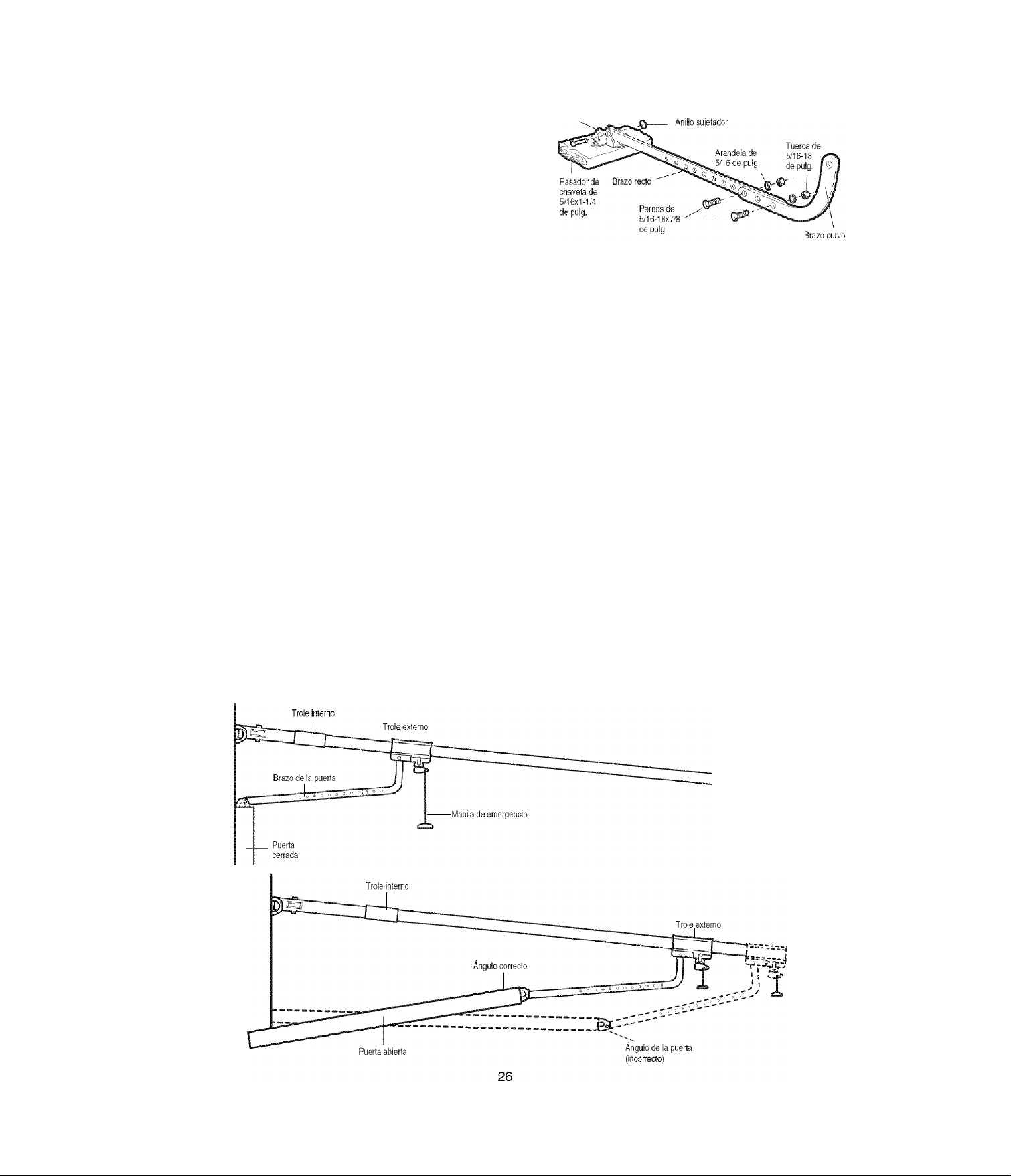
TODAS LAS PUERTAS DE UNA SOLA PIEZA
1. Arme el brazo de la puerta:
• Sujete las dos secciones de los brazos de la puerta
(recto y curvo) a la mayor distancia posible, de manera que
dos o tres de los orificios se sobrepongan uno al otro.
• Cierre la puerta y fije la sección recta de! brazo a la ménsula
de la puerta con el pasador de chaveta de 5/16x1-1/4 de
pulgada.
• Asegúrelos con un anillo sujetador.
• Tire hacia abajo de la manija de separación de emergencia,
desconectando el trole externo del trole interno y deslice el
trole externo hacia la unidad del motor.
• Conecte la sección curvada del brazo de la puerta a la
puerta usando la clavija horquilla de 5/16x1-1/4 de pulg. y
sujetador anular.
NOTA Ajuste los límites en la página siguiente:
• El trole se conecta automáticamente. Si no, consultarla
característica de traba del trole en la página 32.
» Al establecer el límite hacia arriba como se indica en la
página siguiente, la puerta no debe tener una inclinación
“hacia atrás” cuando esté totalmente abierta, como se ilustra
abajo. Una ligera inclinación hacia atrás ocasionará que la
puerta se pandee innecesariamente y/o que la operación no
sea uniforme al abrir o cerrar la puerta desde la posición
totalmente abierta.
Ménsula de la puerta
Page 66

AJUSTES PASO 1
Programar los límites de recorrido
Los límites de recorrido regulan los puntos en que la
puerta debe parar cuando se desplaza hacia arriba o hacia
abajo. Siga los pasos indicados a continuación para
ajustar los límites.
-
Luz dei indicador
- Botón negro
Botón morado
Para programar los límites de desplazamiento:
Ajuste la posición de la puerta usando los botones de color
negro y morado. El negro mueve la puerta hacia ARRIBA (la
abre) y el morado mueve la puerta hacia ABAJO (la cierra).
1. Fijación de ia posición ARRIBA: Oprima sin soltar el botón
negro hasta que la luz indicadora amarilla empiece a
destellar lentamente y después suéltelo.
2. Oprima sin soltar el botón negro hasta que la puerta alcance
la posición ARRIBA (abierta) deseada (Figura 2).
NOTA: Compruebe para asegurarse de que la puerta se abra
lo suficiente para su vehículo.
3. Oprima el control remoto o la consola de control (Figura 3).
Estro fija el límite de ARRIBA (apertura) y empieza a cerrar
la puerta.
NOTA: El movimiento excesivo de la unidad de motor causará
un desgaste prematuro. Vea la sección de Resolución
de problemas.
4. Inmediatamente cuando la puerta empiece a moverse hacia
abajo, oprima y suelte el botón negro o morado. Esto
detendrá la puerta.
5. Fijación de ia posición ABAJO: Oprima sin soltar el botón
morado hasta que la puerta alcance la posición ABAJO
(cerrada) deseada (Figura 4).
6. Una vez que se cierre la puerta, si parece que hay mucha
presión en la puerta, puede mover la puerta hacia uno y otro
lado usando los botones negro y morado para alcanzar la
posición cerrada deseada.
7. Oprima el control remoto o la consola de control (Figura 3).
Esto fija el límite de ABAJO (cierre) y debe poner la puerta
en la posición abierta.
• Si el abridor no se detiene exactamente donde desea,
repita los pasos 1 a 8 y vuelva a programar los límites.
• Cuando la unidad se detenga en las posiciones deseadas
subida (abierta) y bajada (cerrada), vaya al paso 2 de
Ajuste, Fijación de la fuerza.
À ADVERTENCIA
Si el sistema de retroceso de seguridad no se ha instalado
debidamente, las personas (y los niños pequeños en particular)
podrían sufrir LESIONES GRAVES o INCLUSO LA MUERTE cuando
se cierra la puerta de la cochera.
• El ajuste incorrecto de los limites del recorrido de la puerta de la
cochera interferirá con la operación adecuada del sistema de
retroceso de seguridad.
• NUNCA use los ajustes de la fuerza para compensar si la puerta
del garaje se atasca o se atora.
• Después de llevar a cabo CUALQUIER ajuste, SE DEBE probar el
sistema de retroceso de seguridad. La puerta DEBE retroceder ai
entrar en contacto con un objeto de 3.8 cm (1-1/2 de pulg.) de
altura (o bien un pedazo de madera de 5x10 cm (2x4 pulg.)
acostado) en el piso.
PRECAÜGiQN
Para evitar que los vehículos sufran daños, cerciórese de que
cuando la puerta esté completamente abierta haya espacio
suficiente.
Figura 3
Luz del indicador
Figura 4
Oprima cualquiera de los
dos bolones para detener
la puerta. Oprima y
mantenga oprimido eS
bolón morado para
establecer la posición
de ABAJO que usted dei
27
Page 67

AJUSTES PASO 2
Ajustar la fuerza
El botón de ajuste de la fuerza se encuentra en el panel
trasero de la unidad del motor. El ajuste de fuerza medida
la cantidad de potencia que se requiere para abrir y cerrar
la puerta.
1. Ubique ei botón morado en el panel trasero de la unidad
(Figura 1).
2. Oprima el botón morado una vez para que la unidad entre
en modo Ajuste de la fuerza (Figura 2). El LED (luz del
indicador) parpadeará rápidamente.
3. Oprima el botón del control remoto o el control de la puerta
(Figura 3). La puerta se desplazará hasta la posición hacia
ABAJO (cerrada). Oprima el botón del control remoto o el
control de la puerta otra vez para que la puerta se desplace
hasta la posición hacia ARRIBA (abierta). Oprima el botón
del control remoto o el control de la puerta por tercera vez
para que la puerta alcance la posición hacia ABAJO
(cerrada).
El LED (luz del indicador) dejará de parpadear cuando la
unidad haya aprendido el ajuste de fuerza.
La unidad habrá aprendido las fuerzas necesarias para abrir y
cerrar la puerta.
La puerta debe pasar por un ciclo completo hacia ARRIBA y
hacia ABAJO para que la fuerza se establezca correctamente.
Si la unidad no puede abrir y cerrar la puerta por completo,
inspeccione la puerta para asegurarse de que esté
correctamente equilibrada y que no se atasque ni se atore.
Vea la página 3, Preparación de la puerta del garaje.
À ÀDVER1ÉNC1A
Si el sistema de retroceso de seguridad no se ha instalado
debidamente, las personas (y los niños pequeños en particular)
podrían sufrir LESIONES GRAVES o INCLUSO LA MUERTE cuando
se cierra la puerta de la cochera.
• El ajuste incorrecto de los limites del recorrido de la puerta de la
cochera interferirá con la operación adecuada del sistema de
retroceso de seguridad.
• NUNCA use los ajustes de la fuerza para compensar si la puerta
del garaje se atasca o se atora.
• Después de llevar a cabo CUALQUIER ajuste, SE DEBE probar el
sistema de retroceso de seguridad. La puerta DEBE retroceder a!
entrar en contacto con un objeto de 3.8 cm (1-1/2 de pulg.) de
altura (o bien un pedazo de madera de 5x10 cm (2x4 pulg.)
acostado) en el piso.
Figura 1
28
Page 68

AJUSTES, PASO 3
Pruebe el sist&na de reversa de seguridiad
PRUEBA
• Abra completamente la puerta, coloque un pedazo de
madera de 3.8 cm (o un tablón de madera de 2x4 pulg.)
acostado sobre el piso al centro de la puerta del garaje.
• Opere la puerta en la dirección hacia abajo. La puerta
deberá entrar en reversa automáticamente al hacer contacto
con la obstrucción. Cuando logre ejecutar la prueba del
sistema de reversa con éxito, siga con Ajustes paso 4.
AJUSTE
• SI la puerta se detiene al toparse con la obstrucción, esto
significa que el recorrido HACIA ABAJO (cerrar) no es
suficiente. Termine los pasos de progresión 1 y 2 del ajuste
que programan los límites y las fuerzas.
NOTA: Si su puerta es seccional, asegúrese de que los
ajustes al límite no hagan que el brazo de la puerta se
mueva más allá de una posición recta hacia arriba y hacia
abajo. Vea Figura 3, de la página 25.
• Repita la prueba.
• Si la puerta retrocede automáticamente al hacer contacto
con el pedazo de madera de 3.8 cm, quite la obstrucción y
abra y cierre la puerta completamente por lo menos cuatro o
cinco veces para verificar que el ajuste sea adecuado.
• Si la unidad aún no pasa la prueba del sistema de reversa,
llame a un técnico especializado en sistemas de apertura de
puertas.
VERIFICACIÓN li\/IPORTANTE DE SEGURIDAD:
Pruebe del sistema de reversa de seguridad después de que:
• Se hagan ajustes al largo del brazo de la puerta, los limites
del recorrido, o los controles de la fuerza.
• Se hagan reparaciones o ajustes a la puerta del garaje
(incluyendo los resortes y la perner(a).
• Se hagan reparaciones al piso del garaje porque está
desnivelado, etc.
• Se hagan reparaciones o ajustes al abre-puertas.
AjADViRTiNCIÁ;
Si el sistema de reversa de seguridad no se ha instalado
debidamente, las personas (y los niños pequeños en particular)
podrían sufrir LESIONES GRAVES 0 INCLUSO LA MUERTE cuando
se cierre la puerta del garaje.
• El sistema de reversa de seguridad SE DEBE probar cada mes.
• Después de llevar a cabo cualquier ajuste, SE DEBE probar el
sistema de reversa de seguridad. La puerta DEBE retroceder al
entrar en contacto con un objeto de 3.8 cm (1-1/2 de pulg.) de
altura (o un tablón de madera de 2x4 pulg.) acostado en el piso.
' Pedazo de madera de 3.8 cm {1-1/2 de pulg.),
(o un tablón de madera de 5x10 cm (2x4 pulg.)
acostado sobre e! piso)
AJUSTES, PASO 4
Prueba la Sistema de Protección^
• Abra la puerta con el control remoto.
• Coloque en el piso la caja en la que vino embalado el abrepuertas, adonde interfiera con el recorrido de la puerta.
• Comande el cierre de la puerta con el control remoto. La
puerta no se moverá más de 2.5 cm (1 pulgada) y la luz del
abre-puertas comenzará a destellar.
El abre-puertas no ejecutará el cierre con comando remoto si
la luz indicadora de cualquiera de los sensores de seguridad
estuviera apagada (adviertiendo al usuario que los sensores
están desalineados o hay una obstrucción).
Si el abre-puertas comanda et cierre de la puerta con una
obstrucción presente (y los sensores de seguridad no
están instalados a más de 15 cm (6 pulgadas) de altura
sobre el piso), llame a un técnico especializado para
reparar este problema.
29
Page 69

OPERACION
INSTRUCCIONES IMPORTANTES DE SEGURIDAD
ák ADVERTENCIA
Para reducir el riesgo de LESIONES GRAVES o
LA MUERTE:
1. LEA Y SIGA TODAS LAS ADVERTENCIAS Y LAS INSTRUCCIONES
DE OPERACIÓN.
2. SIEMPRE conserve los controles remotos fuera del alcance de ¡os
niños. NUNCA permita que los niños operen o jueguen con los
botones del control de la puerta de la cochera ni con los
controles remotos.
3. SÓLO active la puerta de la cochera siempre y cuando la pueda
ver con claridad, esté debidamente ajustada y no haya ninguna
obstrucción en el recorrido de la puerta al cerrarse.
4. SIEMPRE tenga la puerta de la cochera a la vista hasta que esté
completamente cerrada. NADIE DEBE ATRAVESAR EL RECORRIDO
DE LA PUERTA CUANDO ESTÁ EN MOVIMIENTO.
5. NADIE DEBE PASAR POR DEBAJO DE LA PUERTA SI ESTÁ
DETENIDA Y PARCIALMENTE ABIERTA.
6. De ser posible, use la liberación de emergencia para soltar el trole
SÓLO cuando la puerta de la cochera esté CERRADA. Si los
resortes están débiles o rotos, o bien si la puerta está
desbalanceada, puede que la puerta se caiga rápida y/o
inesperadamente cuando esté abierta.
7. NUNCA use la manija de liberación de emergencia a menos que la
entrada a la cochera esté libre de obstrucciones y no haya
ninguna persona presente.
8. NUNCA use la manija para tirar de !a puerta para abrirla o cerrarla.
Si el nudo de la cuerda se suelta, usted podría caerse.
9. Si ajusta uno de los controles (límites de la tuerza o del
10. Después de llevar a cabo CUALQUIER ajuste, SE DEBE probar el
11. El sistema de retroceso de seguridad SE DEBE probar cada mes.
12. SIEMPRE MANTENGA LA PUERTA DE LA COCHERA
13. Todas las reparaciones necesarias en los cables, resortes y otras
14. Para evitar LESIONES PERSONALES GRAVES o MORTALES
15 CONSERVE ESTAS INSTRUCCIONES.
recorrido), es posibie que sea necesario ajustar también el otro
control.
sistema de retroceso de seguridad,
La puerta DEBE retroceder al entrar en contacto con un objeto
de 3.8 cm (1-1/2 de pulg.) de altura (o bien un pedazo de
madera de 5x10 cm (2x4 pulg.) acostado) en el piso.
DEBIDAMENTE BALANCEADA (vea la página 3). Si la puerta no
está debidamente balanceada podría no retroceder cuando se
requiera, lo que podría ocasionar una LESIÓN GRAVE o
INCLUSO LA MUERTE.
piezas las DEBE llevar a cabo un técnico especializado en
sistemas de puertas, pues todas estas piezas están bajo una
tensión EXTREMA.
debidas a electrocución, desconecte TODA la corriente eléctrica
y de la batería ANTES de realizar cualquier servicio
o mantenimiento.
Cómo Usar su Abridor de Puerta de Cochera
Su abridor Security+® y el control remoto manual han sido
programados en la fábrica con un código coincidente que
cambia cada vez que se usa, accesando ai azar más de
100,000 millones de códigos nuevos. Su abridor funcionará
hasta con 10 controles remotos Security+® y un sistema de
entrada sin llave Security+®. Si compra un control remoto
nuevo, o si desea desactivar algún control remoto, siga las
instrucciones que aparecen en la sección sobre Cómo
programar el abridor.
Active su abridor de aiguna de ias siguientes maneras:
• E! Control remoto manual: Mantenga oprimido el botón
grande hasta que la puerta se empiece a mover.
• La Consola de control de pared: Mantenga oprimido el botón
hasta que la puerta se empiece a mover.
• La Entrada sin llave (Vea Accesorios): Si su abridor de
puerta de cochera viene con este accesorio, deberá estar
programado antes de usarlo. Vea Cómo programar el
abridor.
Una vez activado ei abridor (con ei sensor de seguridad de
retroceso correctamente instaiado y aiineado)
1. Si la puerta está abierta se va a cerrar. Si la puerta está
cerrada se va a abrir.
2. Si la puerta se está cerrando va a retroceder.
3. Si la puerta se está abriendo se va a detener.
4. Si la puerta se ha detenido en un punto parcialmente abierta,
se va a cerrar.
5. Si al cerrarse la puerta se topó con alguna obstrucción, va a
retroceder. Si ia obstrucción interrumpe el rayo del sensor,
las luces del abridor van a parpadear durante cinco
segundos.
6. Si al abrirse la puerta se topó con alguna obstrucción, se va
a detener.
7. Si la puerta está completamente abierta, no va a cerrar si el
rayo está interrumpido. El sensor no tiene ningún efecto en
el ciclo de apertura.
Si el sensor no se ha instalado o está desalineado, la puerta no
se cerrará con el control remoto manual. Sin embargo, la
puerta se puede cerrar con el Control de la puerta, el
Interruptor de llave externo, o la Entrada sin llave, siempre y
cuando los active hasta que el recorrido hacia abajo haya
terminado. Si los suelta demasiado pronto, la puerta va a
retrocederá.
Las tuces del abridor se encenderán en los siguientes casos:
Siempre que conecte el abridor inicialmente; cuando se
restaura el suministro de energía después de una interrupción;
cuando el abridor se activa.
Las luces se apagan automáticamente después de 4 minutos y
1/2 o se quedan encendidas cuando se activa Luz en la
consola de control. Los bombillos deben ser de 100 vatios
máximo.
La función de la luz del Security4^: Las luces se encenderán
también si alguien camina por la puerta de la cochera cuando
está abierta. Si tiene la consola de control de detección de
movimiento, esta función puede desactivarse como sigue; Con
las luces del abridor apagadas, oprima y mantenga oprimido el
botón de la luz durante 10 segundos hasta que la luz se
encienda y se apague de nuevo. Para volver a activar esta
función, empiece el procedimiento con las luces encendidas,
luego oprima y mantenga oprimido el botón de la luz durante
10 segundos hasta que la luz se apague y luego se encienda
de nuevo.
30
Page 70

Cómo usar la consola de control de pared
LA CONSOLA DE CONTROL DE DETECCIÓN
DE MOVIMIENTO
Oprima el botón iluminado para abrir o cerrar la puerta. Oprima
de nuevo para que la puerta retroceda en el ciclo de cierre o
para detener la puerta cuando se está abriendo.
Esta consola de control contiene un detector de movimiento
que encenderá automáticamente la luz cuando detecte la
entrada de una persona en el garaje.
Esta característica puede apagarse fácilmente cuando se usen
extensivamente las luces de trabajo.
Luz
Oprima el botón de Luz para encender o apagar la luz del
aicridor. Este botón no controla las luces del abridor cuando la
puerta está en movimiento. Si usted enciende la luz y luego
activa el abridor, la luz permanecerá encendida durante cuatro
minutos y medio. Oprima el botón nuevamente para que la luz
se apague antes. El intervalo de 4 minutos y 1/2 puede
cambiarse a 1 minuto y 1/2, 2 minutos y 1/2 o 3 minutos y 1/2,
como sigue: Oprima y mantenga oprimido el botón del seguro
(Lock) hasta que la luz empiece a parpadear (alrededor de 10
segundos). Si parpadea una vez, esto indica que el medidor de
tiempo se ha fijado a un minuto y medio. Repita el
procedimiento y la luz parpadeará dos veces, lo que significa
que el intervalo se ha fijado en 2 minutos y 1/2. Repita una vez
más si desea un intervalo de 3 minutos y 1/2, etc., hasta un
máximo de 4 minutos y 1/2, en cuyo caso la luz parpadeará
cuatro veces.
Al usar las luces del abre-puertas como luces de trabajo,
recomendamos que primero inhabilite el detector de
movimiento.
Característica de la Luz de detección de movimiento:
La luz del abridor se encenderá automáticamente cuando una
persona camine por delante de la consola de control de pared.
Esta característica funciona al detectar el movimiento y el calor
del cuerpo y tal vez no funcione a temperaturas de unos 100 °F,
37.7 °C. La luz del abridor se encenderá durante 5 minutos, y
después de apagará automáticamente si no se calcula una
diferencia de movimiento o calor adicionales.
Para desactivar esta característica, oprima el botón de
encendido/apagado automático de la luz del lado izquierdo de
la consola de control.
Recomendamos que desactive el sensor de movimiento cuando
use las luces del abridor como luces de trabajo. De lo contrario
se apagarán automáticamente si está trabajando más allá de la
gama del sensor.
Seguro
Esta función está diseñada para evitar la operación de la puerta
con los controles remotos manuales. No obstante, la puerta se
puede abrir y cerrar con los siguientes accesorios: el Control de
la puerta, el Interruptor de llave externo, y la Entrada sin llave.
Para activar esta función, oprima y mantenga oprimido el botón
del seguro (Lock) por dos segundos. La luz del botón va a
parpadearán mientras esté activado el seguro.
Para desactivar la función, oprima y mantenga oprimido el
botón del seguro por dos segundos. La luz del botón dejará de
parpadear. La función del seguro también se apaga siempre
que el botón “aprender” del panel del motor esté activado.
Característica de Programación
La consola de control está equipada con un botón de
PROGRAMACIÓN para asistir en la programación de los
controles remotos de la unidad. Oprima el botón de
PROGRAMACIÓN una vez para iniciar la modalidad de
PROGRAMACIÓN y la pantalla mostrará Learn Remote
Control - Press Learn Button Again to Confirm (Control de
programación remoto - Oprima nuevamente el botón de
Programación para confirmar). Oprima el botón de
PROGRAMACIÓN por segunda vez y la pantalla mostrará
learn Mode - Press Remote Control Button to Learn Remote’
(Modalidad de Programación - Oprima el botón de control
remoto para programar el control remoto) Oprima el botón del
control remoto que se vaya a programar y la luz de trabajo
destellará para confirmar que se ha programado el control
remoto.
Característica de Horas y minutos
Oprima o mantenga oprimido uno de estos botones laterales
para aumentar las horas o minutos mostrados en la pantalla
LCD.
Característica de Idioma
Oprima este botón lateral para moverse por los tres idiomas Inglés, español y francés.
Característica de Grados (F/C)
Oprima este botón lateral para pasar de grados Fahrenheit a
centígrados y viceversa.
Función adicional cuando se usa con el
control remoto manual de tres funciones
Para controlar las luces del abridor:
Además de la operación de la puerta, también puede
programar el control remoto para el funcionamiento de las
luces.
1. Con la puerta cerrada, oprima y mantenga oprimido un botón
pequeño del control remoto que desee usar para el control
de la luz.
2. Oprima y mantenga oprimido el botón de Luz del control de
la puerta.
3. Mientras mantiene oprimido el botón de Luz, oprima y
mantenga oprimido el botón del seguro (Lock) del control de
la puerta.
4. Después de que las luces del abridor se enciendan
brevemente, suelte todos los botones.
31
Page 71

Mantenimiento de su Abridor de Puerta de Cochera
CALENDARIO DE MANTENIMIENTO
Una vez al mes
• Haga funcionar la puerta manualmente. Si está
desbalanceada o se pandea, llame a un técnico
especializado en sistemas de puertas.
• Revise para cerciorarse de que la puerta se abra y se cierre
completamente. Ajuste los límites de ser necesario (Vea las
páginas 27 y 28).
• Repita la prueba de la retroceso de seguridad. Haga los
ajustes necesarios. (Vea Ajustes, Paso 3.)
Una vez al año
• Ponga aceite en los rodillos, los cojinetes y las bisagras de la
puerta. El abridor no necesita lubricación adicional. No
lubrique los carriles de la puerta.
Cómo Abrir ia Puerta Manuaimente
COMO DESCONECTAR EL TROLE:
La puerta debe estar completamente
cerrada si es posible. Tire de la
manija de liberación de emergencia
(de manera que el brazo de
liberación del trole quede en una
posición vertical) y levante ia puerta
manualmente. La función de seguro
evita que el trole se vuelva a
conectar automáticamente, y la
puerta pueda subirse y bajarse
manualmente con la frecuencia que
sea necesaria.
CÓMO RECONECTAR EL TROLE:
Tire de la manija de liberación de
emergencia hacia el abridor en un
ángulo que el brazo de liberación
del trole quede horizontal. El trole
se reconecta en la siguiente
operación HACIA ARRIBA o HACIA
ABAJO, ya sea manual o mediante
el uso del control de la puerta o del
control remoto.
Posición con el seguro
(desconexión manual)
Trole
Trole
—j
----
-
UJ
o
JrTÜ
Manija de
liberación de
emergencia
(por debajo y por detrás)
LA BATERIA DEL CONTROL REMOTO
À ADVERTENCIA
Para evitar la posibilidad de LESIONES GRAVES o INCLUSO
LA MUERTE:
• NUNCA permita que los niños pequeños estén cerca de
las baterías.
• Si alguien se traga una batería, llame al médico de inmediato.
La batería de litio debe producir
energía durante cinco años. Para
cambiar la batería use el clip del visor
o un destornillador para abrir la caja,
como se indica en la ilustración.
Inserte la batería de acuerdo con las
instrucciónes de polaridad indicadas
en el cubierto del control o en el
tablero electrónico.
Deseche las baterías viejas de la manera adecuada
AVISO: Para cumplir con las regias de la FCC y/o de Canadá (!C}, ajustes o modificaciones de este
receptor y/o emisor están prohibidos, excepto por el cambio de la graduación del código o el reemplazo de
la pila. N0 HAY OTRAS PIEZAS REPARABLES DEL USUARIO.
Se ha probado para cumplir con las normas de la FCC para USO DEL HOGAR 0 DE LA OFICINA, La
operación está sujeta a las dos condiciones siguientes:(1) este dispositivo no puede causar interferencia
perjudicial, y (2) este dispositivo debe aceptar cualquier interferencia recibida, incluyendo la interferencia
que puede causar una operación no deseable.
Abra este extremo
primero para
evitar que
ia caja se
agriete
À ADVERTENCIA
Para evitar la posibilidad de una LESIÓN GRAVE o INCLUSO LA
MUERTE si la puerta de la cochera se cae:
• De ser posible, use la manija de liberación de emergencia para
soltar el trole SÓLO cuando la puerta de la cochera esté
CERRADA. Si los resortes están débiles o rotos, o bien si la
puerta está desbalanceada, la puerta abierta podría caerse rápida
y/o inesperadamente.
• NUNCA use la manija de liberación de emergencia a menos que la
entrada a la cochera esté libre de obstrucciones y no haya
ninguna persona presente.
• NUNCA use la manija para tirar de la puerta para abrirla o cerrarla.
Si el nudo de la cuerda se suelta, usted podría caerse.
Para reconectar
32
Page 72

fleserva de Batería
INSTRUCCIONES DE OPERACIÓN
1. Pruebe la batería con la unidad de motor.
Para probar la BBU, desconecte el cordón de la unidad de
motor de la salida eléctrica.
• Un indicador LED naranja sólido indica que la batería está
operando con energía de baterías.
• Un indicador LED naranja que parpadea con bip indica que
la unidad está operando con energía de batería y que la
carga de la batería está baja.
• Para probar que la batería está funcionando
adecuadamente, abra y cierre la puerta de garaje.
• Vuelva a conectar el cordón de energía de la unidad de
motor a la salida eléctrica.
• Verifique que el indicador LED verde está parpadeando en la
batería (indica que ahora se está cargando la batería).
• Prueba completada.
2. Cargue la batería.
• Permita que las baterías se carguen completamente de 24 a
48 horas antes de usar el sistema de la batería.
Una batería completamente cargada suministra 24V DC a la
unidad de motor durante uno o dos días de operación normal
durante una falla de energía eléctrica. Si el voltaje de la batería
cae a un nivel demasiado bajo, las baterías se desconectarán
y la unidad de motor ya no operará bajo el poder de la batería.
Después de que se ha restaurado la energía eléctrica, las
baterías se recargarán en las siguientes 48 horas. En uso
normal, las baterías durarán de 3 a 5 años.
Para obtener la vida máxima de ia batería y evitar daño,
también desconecte ei respaido de batería si desconecta ei
motor mientras está de vacaciones o durante cuaiquier
otro periodo extenso de tiempo.
NOTA: La operación de puertas puede ser limitada hasta que
las baterías estén completamente cargadas. Las luces de la
unidad de motor no se encenderán durante el modo batería.
A WARNING
Para reducir el riesgo de INCENDIO o LESIONES a las personas:
• Desconecte TODA la corriente eléctrica y de la batería ANTES de
realizar CUALQUIER servicio o mantenimiento.
• Use solamente la pieza Craftsman № 41A822 como batería
de repuesto.
• N0 arroje la batería al fuego. La batería puede estallar.
Compruebe las instrucciones de desechado en los
códigos locales.
Estado de Batería (LED)
NOTA: El indicador LED es mas visible con el luz apagado.
INDICADOR LED VERDE:
Todos los sistemas están normales.
• La luz sólida de un indicador LED indica que las baterías
están totalmente cargadas.
• Un indicador LED que parpadea indica que las baterías se
están cargando.
NOTA: Las baterías no deben estar totalmente cargadas para
operar la unidad de motor.
INDICADOR LED NARANJA;
La unidad de motor ha perdido energía y está operando fuera
de la batería.
• Un indicador LED sólido con bip, que suena
aproximadamente cada 2 segundos, indica que la unidad de
motor está activando la puerta y está operando fuera de la
batería.
• Un indicador LED que parpadea con bip, que suena cada 3(D
segundos, indica que las baterías están bajas.
• Una vez que se restaura la energía, se recargará la batería.
Esto se indica con un indicador LED verde que parpadea.
INDICADOR LED ROJO:
Se ha detectado un error y !a batería se apagará
automáticamente. La batería intentará volverá encenderse
reconectándose a las baterías. Si el error sigue presente, se
apagará otra vez. Este proceso se repetirá cada 5 minutos o
hasta que se haya resuelto el error. Esto se usa para evitar
mayor fuga de las baterías.
• Si un indicador LED rojo permanece encendido cuando se
restaura la energía, y viene acompañado con un bip que
suena cada 30 segundos, favor de llamar para servicio.
33
Page 73

Tiene algún problema (Diagnóstico
de tallas)
NOTA: Desenchufe siempre la batería antes de resolver
problemas.
1. La puerta no cierra y las luces de la unidad del motor
parpadean: El sensor del sistema de retroceso de seguridad
debe estar instalado y alineado correctamente para que el
sistema de apertura de la puerta de la cochera se mueva en
sentido descendente.
• Asegúrese de que los sensores de seguridad estén
instalados y alineados correctamente, y que estén libres de
obstrucciones. Consulte la sección Instalación, Paso 11:
Instale La Sistema de Protecciórf.
• Compruebe los LEO de diagnóstico de la unidad del motor
para ver si parpadean. Luego consulte /a tabla de
diagnóstico en la siguiente página.
2. El control remoto no activa la puerta:
• Compruebe consola de control de detección de
movimiento para ver si parpadea. En caso afirmativo,
desactive el modo de bloqueo siguiendo las instrucciones
de Uso la consola de control de detección de movimiento.
• Vuelva a programar el control remoto según las
instrucciones. Consulte la sección sobre su programación.
• Si el control remoto sigue sin activar la puerta, compruebe
ei LED de diagnóstico de la unidad del motor para ver si
parpadea; luego consulte la tabla de diagnóstico en la
siguiente página,
3. La puerta invierte el movimiento sin ninguna razón
aparente: ajuste la fuerza o los límites del recorrido y repita
la prueba de retroceso de seguridad. Es normal tener que
ajustar la fuerza y los limites del recorrido periódicamente.
Las condiciones atmosféricas pueden afectar al recorrido de
la puerta.
• Compruebe manualmente si la puerta tiene problemas de
equilibrado o si queda atascada.
• Consulte el apartado Ajustes, Paso 2: Ajuste la fuerza.
4. La puerta se cierra completamente, toca el suelo y se
vuelve a abrir, sin ningún motivo aparente: ajuste la
fuerza o los límites del recorrido y repita la prueba de
retroceso de seguridad. Es normal tener que ajustar la
fuerza y los limites del recorrido periódicamente. Las
condiciones atmosféricas pueden afectar al recorrido de la
puerta.
• Consulte el apartado Ajustes, Paso 1: Ajuste los límites del
recorrido hacia ARRIBA y hacia ABAJO.
5. Las luces no se apagan cuando la puerta se abre;
• El sistema de apertura de la puerta de la cochera cuenta
con una función de seguridad de luz. Esta función activa la
luz cuando el haz del sensor está obstruido; Uso la
consola de control de pared, Luz.
Sensor de seguirdad sensor emisor Sensor de seguirdad sensor recepto
(Luz indicadora ámbar) (Luz indicadora verde)
6. La unidad del motor emite un breve zumbido;
• En primer lugar, compruebe si el trole está atascado en el
perno de tope.
• Libere la puerta del abridor tirando de la cuerda de
emergencia.
• Cierre la puerta manualmente.
• Afloje la cadena haciendo girar la tuerca exterior 4 ó 5
vueltas. Se aliviará la tensión.
• Haga funcionar la unidad del motor con el control remoto o
con el conmutador de pared. El trole debe desplazarse
hacia la puerta, y detenerse. Si se engrana con la puerta,
tire de la cuerda de liberación de emergencia para
desengranarlo.
• Disminuya el desplazamiento hacia arriba.
Trole—^
Hffl
3.18 cm
{1-1/4 de pulg,)
• Vuelva a apretar la tuerca exterior hasta que el resorte del
trole esté aproximadamente a 3.18 cm (1-1/4 de pulg.)
de longitud.
• Repita estos pasos si el trole no se libera del perno
de tope.
Indicador LED de estado de batería no illuminado:
• Compruebe los conexiones de la batería.
34
Page 74

Sensor de seguridad
de reversa
Tabla de Diagnóstico
El circuito de los sensores
de seguridad de reversa
está abierto (cable roto o
desconectado).
o BIEN
UJ.I.-IJ.I.IJ.L4
Hay un cortocircuito en el
cable de los sensores de
seguridad de reversa, o los
cables blanco y negro
están invertidos.
.............
El consola de control o el
cable tienen un cortocircuito.
nmmm
Los sensores de seguridad
están ligeramente mal
alineados (LED débil o
parpadeante).
.................
I ni
_________________________________li________________________________
El sistema de apertura de la puerta cuenta con una función de
autodiagnóstico. El botón “Aprender'VLED de diagnóstico
parpadeará varias veces antes de detenerse, indicando que ha
encontrado un posible problema. Consulte la tabla de
diagnóstico a continuación.
I Síntoma: Una o ambas luces indicadoras de los sensores de seguridad no
permanecen encendidas.
• Inspeccione los cables de los sensores para determinar si presentan un cortocircuito
(grapa en el cable), corrija la polaridad de los cables (cables blanco y negro invertidos),
cables rotos o desconectados, sustituir/conectar según proceda.
• Desconecte todos los cables en el dorso de la unidad del motor.
• Quite los sensores de sus soportes y acorte sus cables a 30-60 cm (1-2 pies) desde la
parte posterior de cada sensor.
• Vuelva a conectar la célula transmisora con la unidad del motor, utilizando los cables
cortos. Si la luz indicadora de la célula transmisora permanece encendida, conecte la
célula receptora.
• Alinee los sensores. Si las luces indicadoras se encienden, sustituya los cables de los
sensores. Si las luces de los sensores no se encienden, sustituya los sensores de
seguridad.
I Síntoma: El LED del consola de control no se enciende.
• Inspeccione la unidad de consola de control/cable para ver si tienen un cortocircuito
(grapa clavada en el cable) y sustituya io que proceda.
• Desconecte los cables de la unidad de control de la puerta y haga puente con los
cables. Si la unidad del motor se activa, sustituya la unidad de control.
• Si el motor no se activa, desconecte del motor los cables de consola de control. Con
un cable, haga puente entre los terminales rojo y blanco. Si el motor se activa, cambie
los cables de consola de control.
I Síntoma: La luz indicadora de la célula transmisora permanece encendida; la luz
de la célula receptora es débil o parpadea.
• Vuelva a alinear la célula del sensor del receptor, limpie la lente y asegure ei soporte.
• Asegúrese de que el riel de la puerta esté fijado firmemente a la pared y que no se
mueva.
in I
BZBZESD
El motor se calienta o hay
un posible fallo de RPM.
Desconéctelo para
reiniciarlo.
........
I Síntoma: El motor está muy caliente; El motor no funciona correctamente o el trole
está atascado en el perno de tope = El motor emite un breve zumbido; Sensor de
RPM = Recorrido corto 15-20 cm (6-8 pulg.).
• Desconecte la unidad para reiniciarla. Intente hacer funcionar el motor, compruebe el
código de diagnóstico,
• Si sigue parpadeando 5 veces y el motor se mueve 15-20 cm (6-8 pulg.), cambie el
sensor de RPM.
• Si el motor no funciona, significa que está muy caliente. Deje pasar 30 minutos y
vuelva a intentarlo. Si el motor sigue sin funcionar, cambie el circuito impreso.
35
Page 75

Mensajes de la Consola de Control de Detección de Movimiento de la LCD
Los mensajes siguientes están contenidos dentro de la consola de control de detección de movimiento de LCD y pueden aparecer
durante las operaciones de la unidad:
Significado: Este mensaje aparecerá si ios sensores de inversión de seguridad están
SENSORES DE
SEGURIDAD COMPRUEBE
EL ALINEAMIENTO
OBSTRUCCION O
CABLEADO VEA EL
MANUAL DEL
PROPIETARIO
FUNCIONAMIENTO
DEFECTUOSO DE LOS
SENSORES DE
SEGURIDAD
COMPRUEBE
CONEXIONES DEL
CABLEADO VEA EL
MANUAL DEL
PROPIETARIO
desaiineados, bioqueados o si ios cabies están desconectados. Haga io siguiente para
borrar el mensaje de ia consola de control:
• Compruebe para ver que el área esté despejada entre ios sensors de inversión de seguridad.
• Compruebe para ver que los sensores de inversión de seguridad no estén desalineados.
• Vuelva a alinear el sensor de la célula fotoeléctrica de recepción, limpie la lente y fije los soportes.
• Verifique que el carril de la puerta esté firmemente sujeto a la pared y no se mueva.
• Compruebe para ver que los cables de los sensores de inversión de seguridad estén conectados
a la unidad de motor.
• Si no se ha borrado el mensaje después de las comprobaciones anteriores, consulte el mensaje 2.
I Significado: Este mensaje aparecerá si los sensores de inversión de seguridad están mal
conectados. Haga lo siguiente para borrar el mensaje:
• Inspeccione los cables de los sensores de inversión de seguridad para ver si hay un cortocircuito
(grapa en el cable), polaridad correcta de las conexiones (cables negro/blanco invertidos),
reemplace/conecte según sea necesario.
• Desconecte todos los cables de la parte trasera de la unidad del motor.
• Desconecte los sensores de inversión de seguridad de los soportes y acorte los cables de los
sensores 1-2 pies (30-60 cm) de la parte trasera de cada sensor.
• Vuelva a conectar la célula fotoeléctrica de emisión a la unidad de motor usando cables acortados.
Si el indicador de la célula fotoeléctrica de emisión brilla de forma constante, conecte la célula
fotoeléctrica de recepción.
• Alinee los sensores, si las luces indicadoras brillan, reemplace los cables de los sensores.
Si no se encienden las luces indicadoras de los sensores, reemplace los sensores de
inversión de seguridad.
APRENDA EL
CONTROL REMOTO,
OPRIMA BOTÓN
“APRENDER”OTRA
VEZ PARA CONFIRMAR
LISTO PARA APRENDER
CODIGO DEL CONTROL
REMOTO OPRIMA
BOTÓN DEL CONTROL
REMOTO PARA
APRENDER CODIGO
LISTO PARA
DESACTIVAR CONTROL
REMOTO (LOCK)
CONTROL REMOTO
DESACTIVADO OPRIMA
BOTÓN (LOCK) PARA
REACTIVAR CONTROL
REMOTO
INGLES, FRANCES Y
ESPAÑOL
I Significado: Este mensaje aparecerá cuando se haya oprimido el botón de PROGRAMACIÓN
de la consola de control. Al oprimir nuevamente el botón de PROGRAMACIÓN, se permitirá
que el usuario programe un control remoto adicional del abridor.
I Significado: Este mensaje aparecerá cuando se haya oprimido el botón de programación por
segunda vez en la consola de control o en cualquier momento en el abridor. El abridor está
listo para programar otro control remoto oprimiendo simplemente el botón de control remoto.
Una vez que se haya PROGRAMADO el control remoto, la luz de trabajo destellará una
vez más.
I Significado: Este mensaje aparecerá cuando se haya oprimido el botón de bloqueo sin
soltarlo durante más de un segundo. Esta característica desactivará el abridor de las señales
de control remoto de recepción. Para salir de la modalidad de BLOQUEO, oprima el botón sin
soltarlo durante más de un segundo.
I Significado: Este mensaje aparecerá cuando se haya oprimido el botón de Idioma. Al oprimir
el botón se pasará al idioma siguiente.
SENSOR DE MOVIMIENTO
ENCENDIDO, SENSOR DE
MOVIMIENTO APAGADO
I Significado: Este mensaje aparecerá cuando se haya oprimido el botón de Detección de
movimiento. El detector de movimiento se encenderá y se apagará cada vez que se oprima
el botón.
36
Page 76

COMO PROGRAMAR EL ABRIDOR
AVISO: Si utiliza este abre puertas de garaje Security*^ con un transmisor no dotado de un sistema de códigos de salto (código
aleatorio), se verán circunvenidas las medidas técnicas incorporadas en el receptor del abridor para proteger contra los aparatos de
captura de códigos. El propietario de tos derechos propiedad intelectual del abridor no autoriza ni al comprador ni al proveedor de un
transmisor no dotado de un sistema de códigos de salto (código aleatorio) a circunvenir dichas medidas técnicas.
Su abridor de puerta de cochera ya viene programado de fábrica para operar con su control remoto manual. La puerta se abrirá y se
cerrará cuando oprima el botón grande.
A continuación se proveen las instrucciones para programar su abridor para que opere con controles remotos Security+® adicionales.
Cómo Agregar o Reprogramar un Control Remoto Manual
CÓMO USAR EL BOTÓN LEARN (APRENDER) USO DE LA CONSOLA DE CONTROL DE DETECCIÓN
1. Oprima y suelte el botón “Aprender” de
la unidad del motor. La luz indicadora de
este botón estará encendida por 30
segundos.
2. En los 30 segundos, oprima y mantenga
oprimido el botón del control remoto
manual* que desee usar para su puerta
de cochera.
DE MOVIMIENTO
1. Pulse el botón “Aprender” de la consola
de control de detección de movimiento.
2. Oprima nuevamente el botón “Aprender”
para confirmar la modalidad de
“Aprender”.
3. Oprima el botón del control remoto*
portátil que desee usar para la puerta de
su garaje.
Suelte el botón cuando las luces de la
unidad del motor empiecen a parpadear.
Ya aprendió el código. Si no se han
puesto bombillos, se escucharán dos
chasquidos.
Para Borrar Todos los Códigos de la
Memoria de la Unidad del Motor
Para desactivar cualquier control remoto que no desee usar,
antes que nada borre todos los códigos:
Oprima y mantenga oprimido el botón “Aprender”
de la unidad del motor, hasta que la luz del
Indicador de Aprender se apague
(aproximadamente 6 segundos). Ya estarán
borrados todos los códigos anteriores. Vuelva a
programar cada uno de los controles remotos o la
entrada sin llave que desee usar.
4. Cuando destellen las luces de la unidad
de motor, tiene el código programado. Si
no se han instalado las bombillas, se
oirán dos clics.
*Controles Remotos de 3 Funciones
Si es provisto con su abridor de puerta de la cochera, el botón
grande ha sido programado en la fábrica para operación de su
abridor. Los botones
adicionales de cualquier
control remoto de funciones
múltiples Security+® o de un
minicontrol remoto pueden
programarse para operar otros
abridores de puerta de
cochera Security+®.
37
Page 77

Cómo Agregar, Reprogramar o Cambiar un Código de Entrada sin Liave
NOTA: Su nueva Entrada sin llave debe programarse para que opere el abridor de la puerta de su cochera.
CÓMO USAR EL BOTÓN LEARN (APRENDER) USO DE LA CONSOLA DE CONTROL DE DETECCIÓN
DE MOVIMIENTO
1. Oprima y suelte el botón “Aprender” de
la unidad del motor. La luz indicadora
de este botón estará encendida por 30
segundos.
En los 30 segundos, introduzca un
número de identificación personal (PIN)
que haya elegido, usando el teclado.
Luego oprima y mantenga oprimido ei
botón ENTER.
Suelte el botón cuando las luces de la
unidad del motor empiecen a
parpadear. Ya aprendió el código. Si no
ha instalado bombillos, se escucharán
dos chasquidos.
Para cambiar un PIN existente
Si el PIN existente ya es conocido, una persona lo puede
cambiar sin usar una escalera.
1. Oprima los cuatro botones que correspondan al PIN actual,
luego oprima y mantenga oprimido el botón #.
La luz del abridor parpadeará dos veces. Suelte el botón #.
2. Oprima el nuevo PIN de cuatro dígitos y luego oprima
ENTER.
Las luces de la unidad del motor parpadearán una vez cuando
el PIN se haya aprendido.
Pruebe oprimiendo el nuevo PIN, luego oprima ENTER.
La puerta debe moverse.
Para poner un PIN temporal
Usted puede autorizar el acceso a sus visitas o a personal de
servicio con un PIN temporal de cuatro dígitos. Después de un
determinado número de horas programadas, o número de
accesos, este PIN temporal expira y no vuelve a abrir la puerta.
Se puede usar para cerrar la puerta aún después de que haya
expirado. Haga lo siguiente para poner un PIN temporal:
1. Oprima los cuatro botones correspondientes a su PIN de
entrada personal (no ei último PIN temporal); luego oprima y
mantenga oprimido el botón
La luz del abridor va a parpadear tres veces. Suelte el botón.
NOTA: Este método requiere dos personas si la Entrada sin
llave ya está montada fuera de la cochera.
1. Pulse el botón “Aprender” de la consola
de control de detección de movimiento.
2. Oprima nuevamente el botón “Aprender”
para confirmar la modalidad de
“Aprender”.
3. Introduzca un número de identificación
personal (PIN) que haya elegido, usando
el teclado. Luego oprima y mantenga
oprimido el botón ENTER.
4. Cuando destellen las luces de la unidad
de motor, tiene el código programado.
Si no se han instalado las bombillas, se
oirán dos clics.
2. Oprima los cuatro dígitos del PIN temporal que haya elegido,
luego oprima ENTER.
La luz del abridor va a parpadeará cuatro veces.
3. Para fijar el número de horas que ei PIN temporal debe
funcionar, oprima el número de horas (hasta 255), luego
oprima *.
O
3. Para fijar el número de ireces que el PIN temporal debe
funcionar, oprima el número de veces (hasta 255), luego
oprima #.
La luz del abridor parpadeará una vez cuando el PIN temporal
haya sido aprendido.
Pruebe oprimiendo los cuatro botones correspondientes a! PIN
temporal, luego oprima ENTER. La puerta debe moverse. Si el
PIN temporal se ha lijado para abrir la puerta un determinado
número de veces, recuerde que la prueba constituye una vez.
Para borrar la contraseña temporal, repita los pasos del 1 al 3;
fijando el número de horas o de veces en 0, en el paso 3.
Cierre con un botón: El abridor se puede cerrar presionando sólo el botón ENTER si está activada la función de cierre con un
botón. Esta función viene activada de fábrica. Para activarla o desactivarla, presione y mantenga presionados los botones 1 y 9
durante 10 segundos. El teclado parpadeará dos veces cuando se active la función de cierre con un botón, y parpadeará cuatro
veces cuando se la desactive.
38
Page 78

ACCESORIOS
139.53702
139.53728
139.53729
Liberador de la llave de emergencia:
Se requiere en las cocheras que NO tienen
puerta de acceso. Permite al dueño de la
casa abrir la puerta de la cochera
manualmente desde el exterior,
desconectando el trole.
Extensión del riel de 2.4 m (8 pies):
Permite que una puerta de 2.4 m (8 pies) se
abra compietamente.
Extensión del riel de 3 m (10 pies):
Permite que una puerta de 3 m (10 pies) se
abra compietamente.
Ménsulas de extensión:
(Sólo están disponibles a través de
Refacciones y Servicio Sears)
(Opcionales) Para la instalación del sensor
de seguridad en la pared o en el piso.
139.53589
139.53752
139.53754
41A6344
Ménsulas de soporte:
Para cielos rasos sin acabados o en los
casos en que se necesite soporte adicional,
basado en la construcción de la cochera.
Incluye las ménsulas y los sujetadores.
SECURITY+® Control remoto de
3 funciones:
Incluye el clip del visor.
SECURITY+® Control remoto compacto
de 3 funciones:
Con lazada para ponerse en el llavero.
SECURITY+® Entrada sin llave:
Permite al dueño de la casa operar la
puerta de la cochera desde el exterior,
ingresando una contraseña. También puede
agregarse una contraseña temporal para
visitas o personal de servicio.
Consola de control sin cable
(Sóio están disponibles a través de
Refacciones y Servicio Sears)
139.53709
Ménsulas para la altura de la puerta:
(Sólo para puertas seccionales)
Sustituyen a las ménsulas superiores y los
rodillos de la puerta para reducir la altura del
recorrido de la puerta. Para usarse cuando
se instala el abridor en una cochera con
poca tolerancia (altura).
139.53749
Ö
h
Control de luz enchufable:
Permite ai dueño de la casa encender una
lámpara, la televisión, u otro aparato
doméstico con el control remoto desde el
coche, la cama, o dondequiera que se
encuentre en la casa.
GARANTIA
GARANTIA SEARS
Durante 90 dias a partir de la fecha de compra, Sears hará las reparaciones de su abridor de puerta de cochera sin costo para usted si el abridor tiene
defectos en materiales o mano de obra.
Desde el dia 91 hasta 3 años, apartir de la fecha de compra, Sears hará las purtes de repustos para ninguno parte gue tiene defectos, sin costo. Usted
paga la mano de obra.
Desde el dia 91 hasta 10 años, si el motor del abridor de puerta de cochera está defectuoso. Sears proporcionará un motor de repuesto, sin costo alguno.
Usted paga la mano de obra.
SEARS NO SERÁ RESPONSABLE POR LAS PÉRDIDAS O DAÑOS QUE SUFRA LA PROPIEDAD, NI POR PÉRDIDAS O GASTOS INCIDENTALES O
CONSECUENTES DERIVADOS DE DAÑOS A LA PROPIEDAD QUE PUDIERAN DIRECTA O INDIRECTAMENTE SER EL RESULTADO DEL USAR ESTE
PRODUCTO. En algunos estados no está permitido la exclusión o límite de los daños incidentales o consecuentes, de manera que el límite o exclusión
arriba citado puede no aplicar en su caso.
Esta garantía no cubre focos ni piezas de repuesto necesarias cuando este producto se ha tratado indebidamente o con negligencia, incluyendo no llevar a cabo la
instalación, ajuste y operación de este abridor de puerta de cochera de acuerdo a las instrucciones contenidas en el instructivo del propietario.
EL SERVICIO DE GARANTÍA ESTÁ DISPONIBLE CON PONERSE EN CONTACTO CON EL CENTRO DE SERVICIO SEARS MÁS CERCANO EN LOS ESTADOS
UNIDOS.
Esta garantía aplica solamente mientras este producto se esté usando en los Estados Unidos.
Esta garantía le otorga derechos legales específicos, y usted podría tener otros derechos que pueden ser diferentes en cada estado.
EL ABRIDOR DE PUERTA DE COCHERA TIENE UNA GARANTÍA COMPLETA DE 90 DIAS
GARANTÍA LIMITADA
GARANTÍA LIMITADA DEL MOTOR
LÍMITE DE LA RESPONSABILIDAD
Sears, Roebuck and Co., Dept. 817WA, Hoffman Estafes, IL 60179
[§JMBJM1J1ÍÍBJMBJ1ÍÍ1JMBJ1ÍíeU1ÍÍBJ1ÍÍBJ1ÍÍBJ1ÍíeU1ÍÍBJMeU1ÍÍBJMeU1ÍÍBJ^^
39
Page 79

Get it fixed, at your home or ours!
Your Home
For repair-in your home-of all major brand appliances,
lawn and garden equipment, or heating and cooling systems,
no matter who made it, no matter who sold it!
For the replacement parts, accessories and
owner’s manuals that you need to do-it-yourself.
For Sears professional installation of home appliances
and items like garage door openers and water heaters.
1-800-4-MY-HOME® (1-800-469-4663)
Call anytime, day or night (U.S.A. and Canada)
www.sears.com www.sears.ca
Our Home
For repair of carry-in items like vacuums, lawn equipment,
and electronics, call or go on-line for the location of your nearest
Sears Parts & Repair Center.
1 -800-488-1222
Call anytime, day or night (U.S.A. only)
www.sears.com
To purchase a protection agreement (U.S.A.)
or maintenance agreement (Canada) on a product serviced by Sears:
1-800-827-6655 (U S A.) 1-800-361-6665 (Canada)
Para pedir servicio de reparación
a domicilio, y para ordenar piezas:
1-888-SU-HOGAR^^
(1-888-784-6427)
Au Canada pour service en français:
1-800-LE-FOYER^'=
(1-800-533-6937)
www.sears.ca
114A3280B
® Registered Trademark / ™ Trademark / ™ Service Mark of Sears, Roebuck and Co.
@ Marca Registrada / ™ Marca de Fábrica / Marca de Servicio de Sears, Roebuck and Co,
Marque de commerce / “° Marque déposée de Sears, Roebuck and Co.
© 2006 Sears, Roebuck and Co.
 Loading...