

Craftsman 13953914 Owner’s Manual
Owner's Manual/Manual Del Propietario
1/2 HP
GARAGE DOOR OPENER
ABRIDOR DE PUERTA DE COCHERA
For Residential Use Oniy/Sbio para uso residencial
Model/Modelo • 139.53914
m
Read and follow all safety rules
and operating instructions before
first use of this product.
Fasten the manual near the garage
door after installation.
Periodic checks of the opener are
required to ensure safe operation.
m
o_
Z_
Leer y seguir todas ias regias de
seguridad y las instrucciones de
operacibn antes de usar este
producto por primera vez.
Guardar este manual cerca de la
puerta de la cochera.
Se deben realizar revisiones
peribdicas del abridor de puertas
para asegurar su operacibn
segura.
Sears, Roebuck and Co., Hoffman Estates, IL 60179 U.S.A
www.sears.com/craftsman
TABLE OF CONTENTS
Introduction 2.7
Safety symbol and signal word review ........................ 2
Preparing your garage door ........................................ 3
Tools needed ............................................................... 3
Planning .................................................................. 4-5
Carton inventory .......................................................... 6
Hardware inventory ..................................................... 7
Assembly 8-11
Assemble the rail and install the trolley ...................... 8
Fasten the rail to the motor unit and
install the idler pulley ................................................... 9
install the belt and attach the belt cap retainer ......... 10
Set the tension .......................................................... 11
Installation 11.26
installation safety instructions .................................... 11
Determine the header bracket location ..................... 12
install the header bracket .......................................... 13
Attach the rail to the header bracket ......................... 14
Position the opener ................................................... 15
Hang the opener ....................................................... 16
install the door control ............................................... 17
install the lights ......................................................... 18
Attach the emergency release rope and handle .......18
Electrical requirements .............................................. 19
install The Protector System ®.............................. 20-22
Fasten the door bracket ....................................... 23-24
Connect the door arm to the trolley ..................... 25-26
Adjustment 27.29
Adjust the travel limits ............................................... 27
Adjust the force ......................................................... 28
Test the safety reversal system ................................. 29
Test The Protector System ®...................................... 29
Operation 30.34
Operation safety instructions ..................................... 30
Using your garage door opener ................................ 30
Using the walt-mounted Door Control ....................... 31
To open the door manually ........................................ 31
Care of your garage door opener .............................. 32
Having a problem? .................................................... 33
Diagnostic chart ......................................................... 34
Programming 35-36
To add or reprogram a hand-held remote control .....35
To erase all codes ..................................................... 35
3-Function Remotes .................................................. 35
To add, reprogram or change
a Keyless Entry PIN .................................................. 36
Repair Parts 37.38
Rail assembly parts ................................................... 37
installation parts ........................................................ 37
Motor unit assembly parts ......................................... 38
Accessories 39
Warranty
Repair Parts and Service
39
40
INTRODUCTION
Safety Symbol
and Signal Word Review
This garage door opener has been designed and tested to offer safe service provided it is installed, operated,
maintained and tested in strict accordance with the instructions and warnings contained in this manual.
When you see these Safety Symbols and Signal
Words on the following pages, they will alert you to
Mechanical
Electrical
the possibility of serious injury or death if you do
not comply with the warnings that accompany them.
The hazard may come from something mechanical
or from electric shock. Read the warnings carefully.
When you see this Signal Word on the following
pages, it will alert you to the possibility of damage to
your garage door and/or the garage door opener if
you do not comply with the cautionary statements
that accompany it. Read them carefully.
2
Preparing your garage door
Before you begin:
• Disable locks
• Remove any ropes connected to garage door
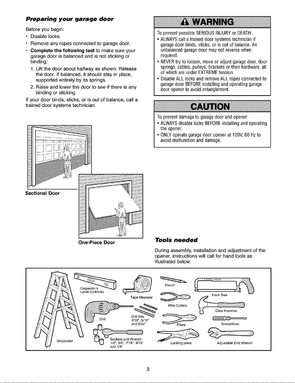
• Complete the following test to make sure your
garage door is balanced and is not sticking or
binding:
1 Lift the door about halfway as shown. Release
the door. If balanced, it should stay in place,
supported entirely by its springs.
2 Raise and lower the door to see if there is any
binding or sticking
If your door binds, sticks, or is out of balance, call a
trained door systems technician.
To prevent possibleSERIOUSINJURYor DEATH:
• ALWAYScall a trained door systems technician if
garage door binds, sticks, or is out of balance.An
unbalancedgaragedoor maynot reversewhen
required
• NEVERtry to loosen, move or adjust garagedoor,door
springs, cables,pulleys, brackets or their hardware,all
of which are under EXTREMEtension.
• DisableALL locks and remove ALLropes connectedto
garage door BEFOREinstalling and operating garage
door openerto avoid entanglement.
To preventdamageto garagedoor and opener:
• ALWAYSdisable locks BEFOREinstalling and operating
the opener.
• ONLYoperategaragedoor openerat 120V,60 Hz to
avoid malfunction and damage
Sectional Door
One-Piece Door
Tools needed
During assembly, installation and adjustment of the
opener, instructions will call for hand tools as
illustrated below.
Carpenter's _ _1 _ J_ \;_
Level (optional) _ _ Hack Raw °_ _1
Tape Measure _ f_ -- -
_ Wire Cutters / ";""_
Drill Bits
_k_ and 5/32" Pliers Screwdriver
Stepladder U e c _ _ v
O0 o
1/2,6/8,7/16,9/16 Locking pl_ers Adlustable End Wrench
and 1/4"
_ Claw Hammer
3
Planning
Identify the type and height of your garage door.
Survey your garage area to see if any of the
conditions below apply to your installation. Additional
materials may be required. You may find it helpful to
refer back to this page and the accompanying
illustrations as you proceed with the installation of
your opener.
Depending on your requirements, there are several
installation steps which may call for materials or
hardware not included in the carton.
• Installation Step 1 - Look at the walt or ceiling
above the garage door. The header bracket must
be securely fastened to structural supports.
• Installation Step 5 - Do you have a finished ceiling
in your garage? If so, a support bracket and
additional fastening hardware may be required.
• Installation Step 10 - Depending upon garage
construction, extension brackets or wood blocks
may be needed to install sensors.
• Installation Step 10 -Alternate floor mounting of
the safety reversing sensor will require hardware
not provided.
Do you have an access door in addition to the
garage door? If not, Model 53702 Emergency Key
Release is required. See Accessories page.
Look at the garage door where it meets the floor.
Any gap between the floor and the bottom of the
door must not exceed 1/4" (6 mm). Otherwise, the
safety reversal system may not work properly. See
Adjustment Step 3. Floor or door should be
repaired.
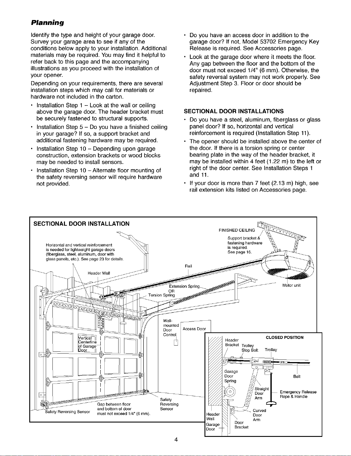
SECTIONAL DOOR INSTALLATIONS
Do you have a steel, aluminum, fiberglass or glass
panel door? If so, horizontal and vertical
reinforcement is required (Installation Step 11).
The opener should be installed above the center of
the door. If there is a torsion spring or center
bearing plate in the way of the header bracket, it
may be installed within 4 feet (1.22 m) to the left or
right of the door center. See Installation Steps 1
and 11.
If your door is more than 7 feet (2.13 m) high, see
rail extension kits listed on Accessories page.
SECTIONAL DOOR INSTALLATION
Horizontal and vertical reinforcement
is needed for lightweight garage doors
(fiberglass, steel, aluminum, door with
glass panels, etc.). See page 23 for details.
Header Wall
Gap between floor Reversing
and bottom of door Sensor
must not exceed 1/4" {6 mm).
j Torsion Spring
OR
Walt*
moun_d
Door Access Door
Cont_l
Safety
Rail
Extension Spring
FINISHED CEILING
Support bracket &
fastening hardware
is required.
See page 16.
Header
Brack_ T_lley
S_p Bolt T_lley
Gamge
Door
Sp_ng
B_cket
)runit
CLOSED POSITION
Belt
Emergency Release
Rope & Handle
Curved
Door
Arm
4
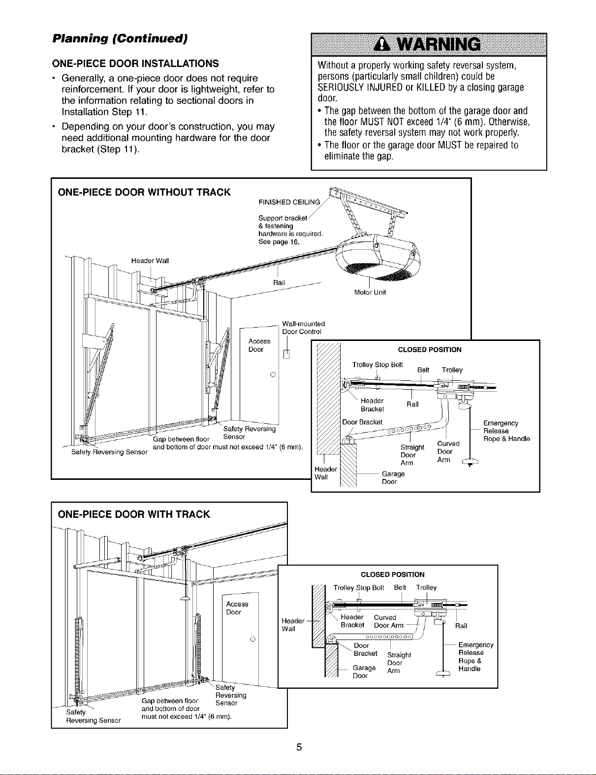
Planning (Continued)
ONE-PIECE DOOR INSTALLATIONS
• Generally, a one-piece door does not require
reinforcement. If your door is lightweight, refer to
the information relating to sectional doors in
Installation Step 11.
• Depending on your door's construction, you may
need additional mounting hardware for the door
bracket (Step 11).
ONE-PIECE DOOR WITHOUT TRACK
FINISHED CEILING
Support bracket,
& fastening
hardware is required.
See page 16.
ACCESS
Safety Reversing
f
Safety Reversing Sensor
Gap between floor
and bottom of door must not exceed 1/4" (6 mm).
Sensor
Rail
Wall-mounted
D_or Control
Without a properly working safety reversalsystem,
persons (particularly smallchildren) could be
SERIOUSLYINJUREDor KILLEDby a closing garage
door.
• The gap betweenthe bottom of the garagedoor and
the floor MUSTNOTexceed 1/4" (6 ram). Otherwise,
the safety reversalsystem may not work properly.
• The floor or the garagedoor MUST be repairedto
eliminate the gap.
Motor Unit
CLOSED POSITION
Trolley Stop Bolt
Belt Trolley
Bracket
Door Bracket Emergency
Straight Curved
Door Door
leader
Vail
Arm Arm •
Garage
Release
Rope & Handle
ONE-PIECE DOOR WITH TRACK
J and bottom of door
Safety must not exceed 1/4" (6 mm).
Reversing Sensor
Gap between floor Sensor
Access I
Door I
Reversing
Trolley Stop Bolt Belt Trolley
_Nea_le _ \Bracket DoorArm_ Rail
ol
CLOSED POSITION 1
DOO_..... Doorl..... )j !_ i_ergenCYRope&
1_ Bracket Straight Release
DGoararge Arm Handle
5
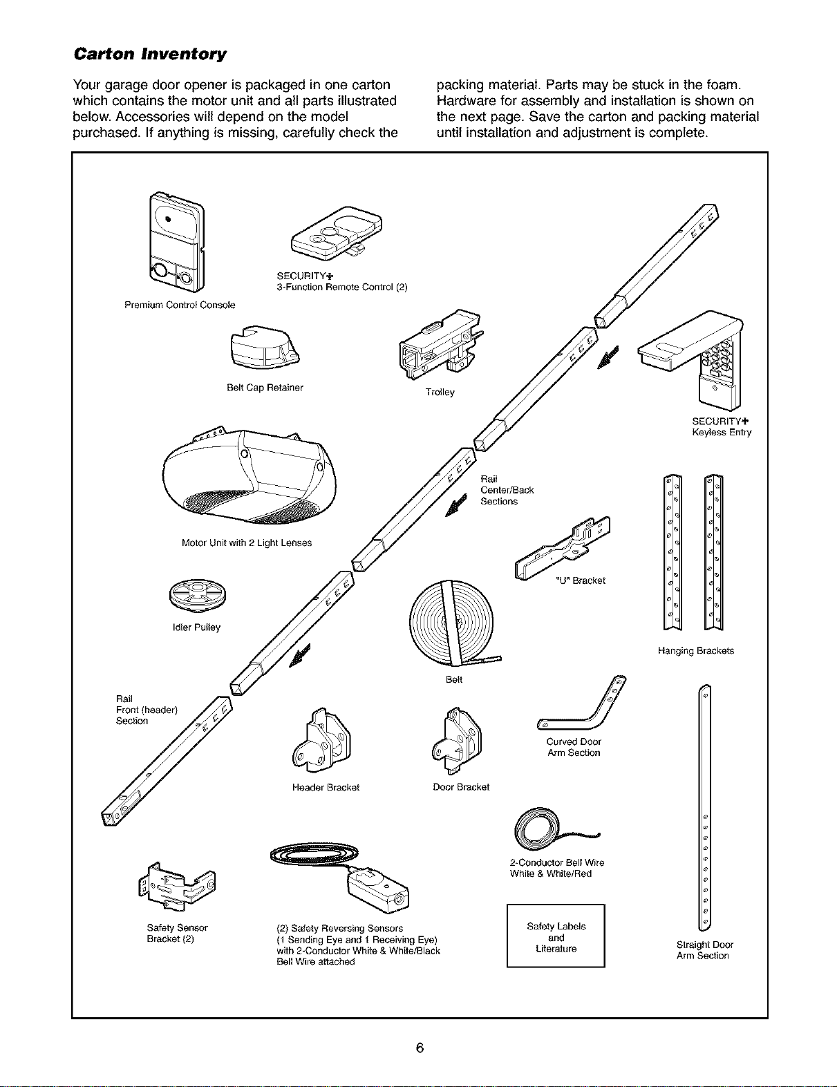
Carton Inventory
Your garage door opener is packaged in one carton
which contains the motor unit and all parts illustrated
below. Accessories wilt depend on the model
purchased. If anything is missing, carefully check the
SECURITY_
3-Function Remote Control (2)
Premium Control Console
Belt Cap Retainer
packing material. Parts may be stuck in the foam.
Hardware for assembly and installation is shown on
the next page. Save the carton and packing material
until installation and adjustment is complete.
Trolley
SECURITY_
Keyless Entry
Rai_
Center/Back
Sections
Motor Unit with 2 Light Lenses
Idler Pulley
Rraolnt(header)
Y
Safety Sensor
Bracket (2)
Header Bracket
(2) Safety Reversing Sensors
(1 Sending Eye and I Receiving Eye)
with 2-Conductor White & White/Black
Bell Wire attached
Be_t
Door Bracket
Curved Door
Arm Section
2*Conductor Bell Wire
White & White/Red
Safety Labels
and
Literature
11
Hanging Brackets
Straight Door
Arm Section
6
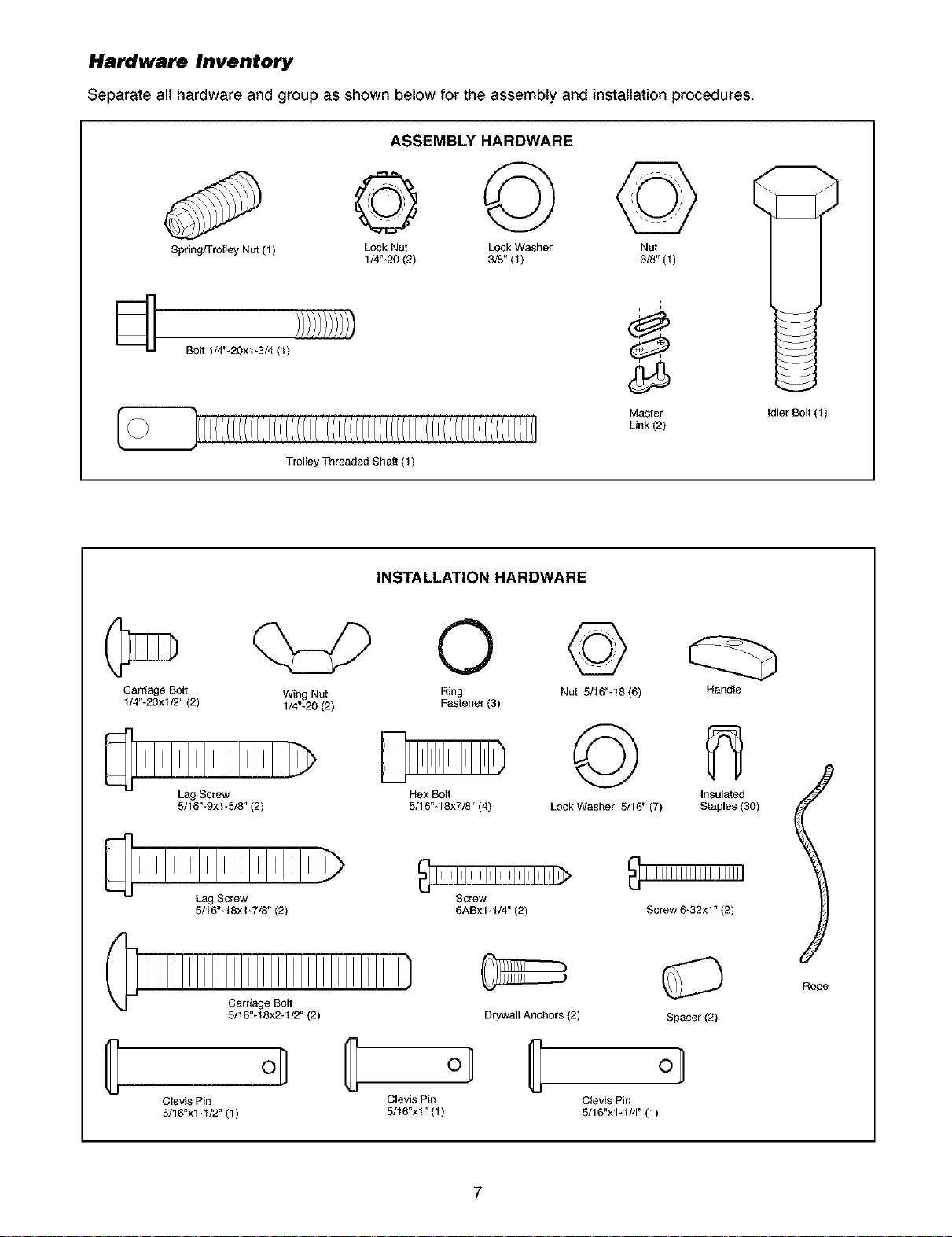
Hardware Inventory
Separate all hardware and group as shown below for the assembly and installation procedures.
ASSEMBLY HARDWARE
© ©©
Spring/Trolley Nut (1)
@
@
Carriage Bolt
1/4"-20xl/2" (2)
Bolt 1/4"-20x1-3/4 (1)
q:p ©
Lock Nut Lock Washer Nut
1/4"-20 (2) 3/8" (1) 3/8" (1)
Trolley Threaded Shaft (1)
INSTALLATION HARDWARE
Wing Nut Ring
1/4"-20 (2) Fastener (3)
©
Nut 5/16"-18 (6)
Master
Link (2)
i
Idler Bolt (1)
Handle
@
Clevis Pin
5/16"x1-1/2" (1)
Lag Screw
5/16"-9x%5/8"(2)
Lag Screw
5/16"-18xl-7/8"(2)
Carriage Bolt
5/16"-18x2-1/2" (2)
o_
©
Hex Bolt
5/16"-18x7/8" (4)
Screw
6ABx1-1/4" (2) Screw 6-32x1"(2)
Drywall Anchors (2)
ol IE ol
Clevis Pin Clevis Pin
5/16"xl" (1) 5116"xl -1/4" (1)
7
Lock Washer 5/16" (7)
Insulated
Staples (30)
l
Rope
Spacer(2)
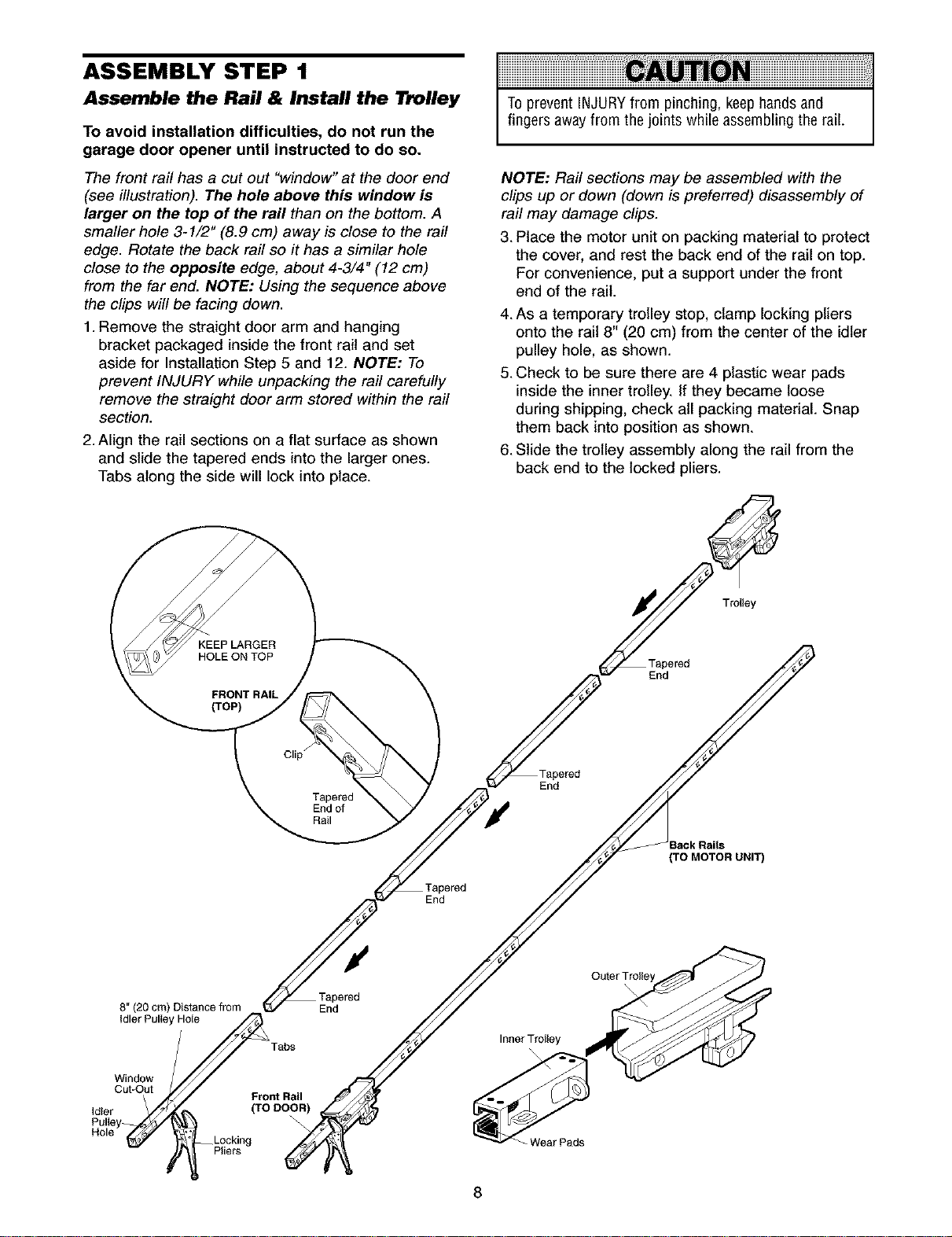
ASSEMBLY STEP 1
Assemble the Rail & Install the l_olley
To avoid installation difficulties, do not run the
garage door opener until instructed to do so.
The front rail has a cut out "window" at the door end
(see illustration). The hole above this window is
larger on the top of the rail than on the bottom. A
smaller hole 3-1/2" (8.9 cm) away is close to the rail
edge. Rotate the back rail so it has a similar hole
close to the opposite edge, about 4-3/4" (12 cm)
from the far end. NOTE: Using the sequence above
the clips will be facing down.
1. Remove the straight door arm and hanging
bracket packaged inside the front rail and set
aside for Installation Step 5 and 12. NOTE: To
prevent INJURY while unpacking the rail carefully
remove the straight door arm stored within the rail
section.
2. Align the rail sections on a flat surface as shown
and slide the tapered ends into the larger ones.
Tabs along the side will lock into place.
To prevent INJURYfrom pinching, keep hands and
fingers away from the joints while assembling the rail.
NOTE: Rail sections may be assembled with the
clips up or down (down is preferred) disassembly of
rail may damage clips.
3. Place the motor unit on packing material to protect
the cover, and rest the back end of the rail on top.
For convenience, put a support under the front
end of the rail.
4. As a temporary trolley stop, clamp locking pliers
onto the rail 8" (20 cm) from the center of the idler
pulley hole, as shown.
5.Check to be sure there are 4 plastic wear pads
inside the inner trolley. If they became loose
during shipping, check all packing material. Snap
them back into position as shown.
6.Slide the trolley assembly along the rail from the
back end to the locked pliers.
KEEP LARGER
HOLE ON TOP
FRONT RAIL
(TOP)
8" (20 cm) Distance from
FHole
Tabs
Clip
Tapered
End of
Rail
End
End
End
Inner Trolley
Tapered
End
(TO MOTOR UNIT)
Trolley
Window
Idleru,t,_u__Pulle _
Cut-Out nt Rail
Idler _._ (TO DOOR)
Pulley
Hole __Locking
Pliers
Wear Pads
8
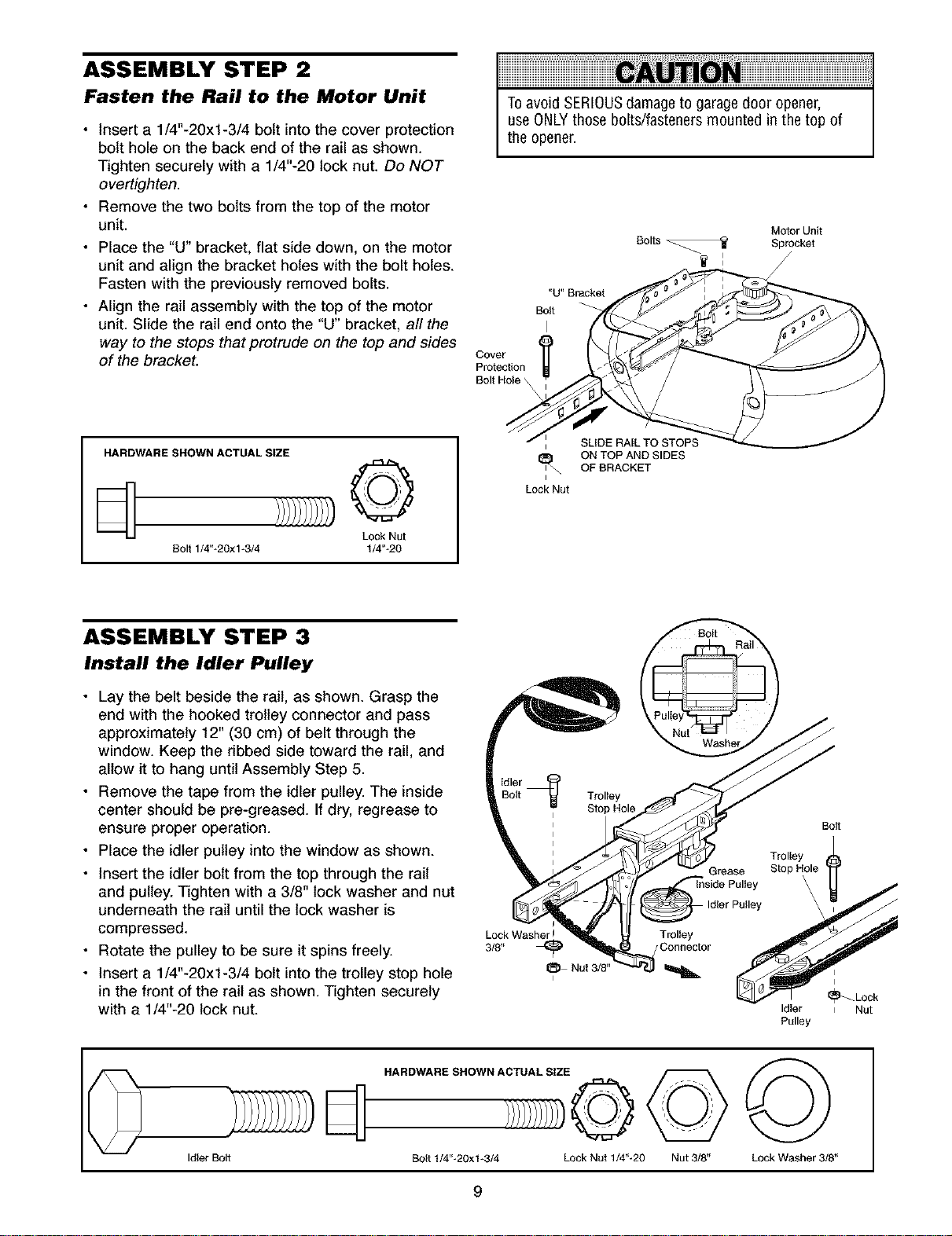
ASSEMBLY STEP 2
Fasten the Rail to the Motor Unit
• Insert a 1/4"-20xl-3/4 bolt into the cover protection
bolt hole on the back end of the rail as shown.
Tighten securely with a 1/4"-20 lock nut. Do NOT
overtighten.
• Remove the two bolts from the top of the motor
unit.
• Place the "U" bracket, flat side down, on the motor
unit and align the bracket holes with the bolt holes.
Fasten with the previously removed bolts.
• Align the rail assembly with the top of the motor
unit. Slide the rail end onto the "U" bracket, all the
way to the stops that protrude on the top and sides
of the bracket.
HARDWARE SHOWN ACTUAL SIZE
©
Lock Nut
Bolt 1/4"-20xl-3/4 1/4"-20
Toavoid SERIOUSdamageto garagedoor opener,
useONLYthose bolts/fasteners mounted in the top of
the opener.
Bolts
"U" Bracket
Bolt
I
Cover
Protection
Bolt Hole '
SLIDE RAIL TO STOPS
I
ON TOP AND SIDES
OF BRACKET
I
Lock Nut
Motor Unit
Sprocket
ASSEMBLY STEP 3
Install the Idler Pulley
• Lay the belt beside the rail, as shown. Grasp the
end with the hooked trolley connector and pass
approximately 12" (30 cm) of belt through the
window. Keep the ribbed side toward the rail, and
allow it to hang until Assembly Step 5.
• Remove the tape from the idler pulley. The inside
center should be pre-greased. If dry, regrease to
ensure proper operation.
• Place the idler pulley into the window as shown.
• Insert the idler bolt from the top through the rail
and pulley. Tighten with a 3/8" lock washer and nut
underneath the rail until the lock washer is
compressed.
• Rotate the pulley to be sure it spins freely.
• Insert a 1/4"-20xl-3/4 bolt into the trolley stop hole
in the front of the rail as shown. Tighten securely
with a 1/4"-20 lock nut.
HARDWARE SHOWN ACTUAL SIZE
Lock Washer
3/8"
I_) Nut 3/8"
I
Bolt
Grease Stop Hole
Idler Pulley
inside Pulley _
Trolley j _
Connector .,,_lV_ _1_
Trolley
Idler L Nut
Pulley
Idler Bolt
Bolt t/4"-20xl*3/4 Lock Nut 1/4"-20 Nut 3/8" Lock Washer 3/8"
9
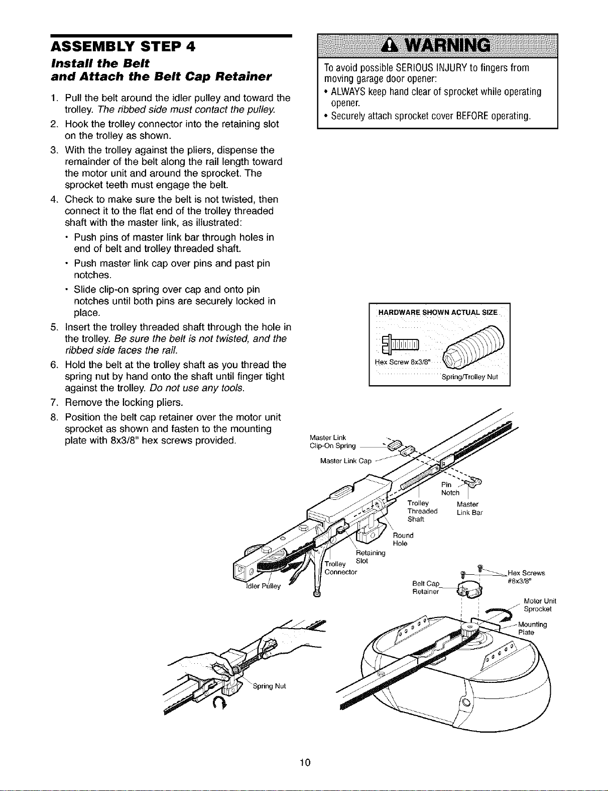
ASSEMBLY STEP 4
Install the Belt
and Attach the Belt Cap Retainer
1. Pull the belt around the idler pulley and toward the
trolley. The ribbed side must contact the pulley.
2. Hook the trolley connector into the retaining slot
on the trolley as shown.
3. With the trolley against the pliers, dispense the
remainder of the belt along the rail length toward
the motor unit and around the sprocket. The
sprocket teeth must engage the belt.
4. Check to make sure the belt is not twisted, then
connect it to the flat end of the trolley threaded
shaft with the master link, as illustrated:
• Push pins of master link bar through holes in
end of belt and trolley threaded shaft.
• Push master link cap over pins and past pin
notches.
• Slide clip-on spring over cap and onto pin
notches until both pins are securely locked in
place.
5. Insert the trolley threaded shaft through the hole in
the trolley. Be sure the belt is not twisted, and the
ribbed side faces the rail.
6. Hold the belt at the trolley shaft as you thread the
spring nut by hand onto the shaft until finger tight
against the trolley. Do not use any tools.
7. Remove the locking pliers.
8. Position the belt cap retainer over the motor unit /_
sprocket as shown and fasten to the mounting /_/.,,_/
Toavoid possible SERIOUSINJURYto fingersfrom
moving garage door opener:
• ALWAYSkeep handclear of sprocket while operating
opener.
• Securely attach sprocket cover BEFOREoperating.
HARDWARE SHOWN ACTUAL SIZE
Hex Screw 8x3/8"
Spring/Trolley Nut
plate with 8x3/8 hex screws provided." _lla_t_rnL&pkring _/__/
Master Link Cap "- "
C:) Shaft
@ Round
Retaining
Trolley Slot
f -Mounting
Threaded Link Bar
MOtOr Unit
: J Sprocket
Plate
lO
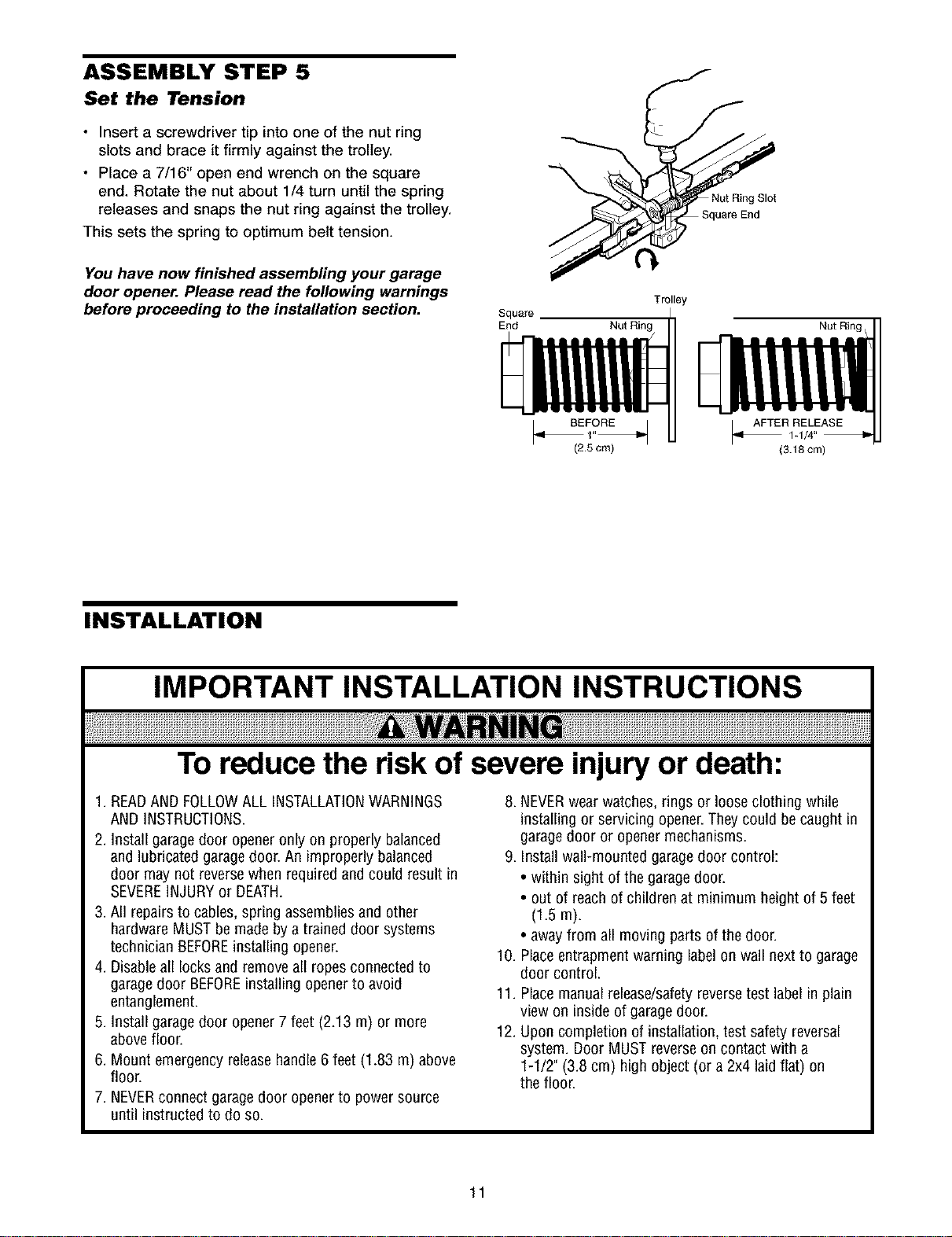
ASSEMBLY STEP 5
Set the Tension
• Insert a screwdriver tip into one of the nut ring
slots and brace it firmly against the trolley.
• Place a 7/16" open end wrench on the square
end. Rotate the nut about 1/4 turn until the spring
releases and snaps the nut ring against the trolley.
This sets the spring to optimum belt tension.
You have now finished assembling your garage
door opener. Please read the following warnings
before proceeding to the installation section.
Square
End Nut Ring
(2.5 cm) (3.18 cm)
J
Nut Ring Slot
Trolley
Nut Ring,
INSTALLATION
IMPORTANT INSTALLATION INSTRUCTIONS
To reduce the risk of severe injury or death:
1. READAND FOLLOWALL INSTALLATIONWARNINGS
AND INSTRUCTIONS.
2. Install garage door opener only on properly balanced
and lubricated garagedoor. An improperly balanced
door may not reversewhen requiredand could result in
SEVEREINJURYor DEATH.
3. All repairs to cables, spring assembliesand other
hardware MUSTbe made by a trained door systems
technician BEFOREinstalling opener.
4. Disableall locksand remove all ropes connected to
garagedoor BEFOREinstalling openerto avoid
entanglement.
5. Install garage door opener 7feet (2.13 m) or more
abovefloor.
6. Mount emergency releasehandle 6 feet (1.83 m) above
floor.
7. NEVERconnect garage door openerto power source
until instructed to do so.
8. NEVERwear watches,rings or loose clothing while
installing or servicing opener.Theycould becaught in
garage door or opener mechanisms.
9. Install wall-mounted garagedoor control:
• within sight of the garage door.
• out of reach of children at minimum height of 5 feet
(1.5m).
• away from all moving parts of the door.
10. Placeentrapment warning labelon wall next to garage
door control.
11. Placemanualrelease/safetyreversetest label in plain
view on inside of garage door.
12. Uponcompletion of installation, test safety reversal
system. Door MUST reverseon contact with a
1-1/2" (3.8 cm) high object (or a 2x4 laid flat) on
the floor.
11
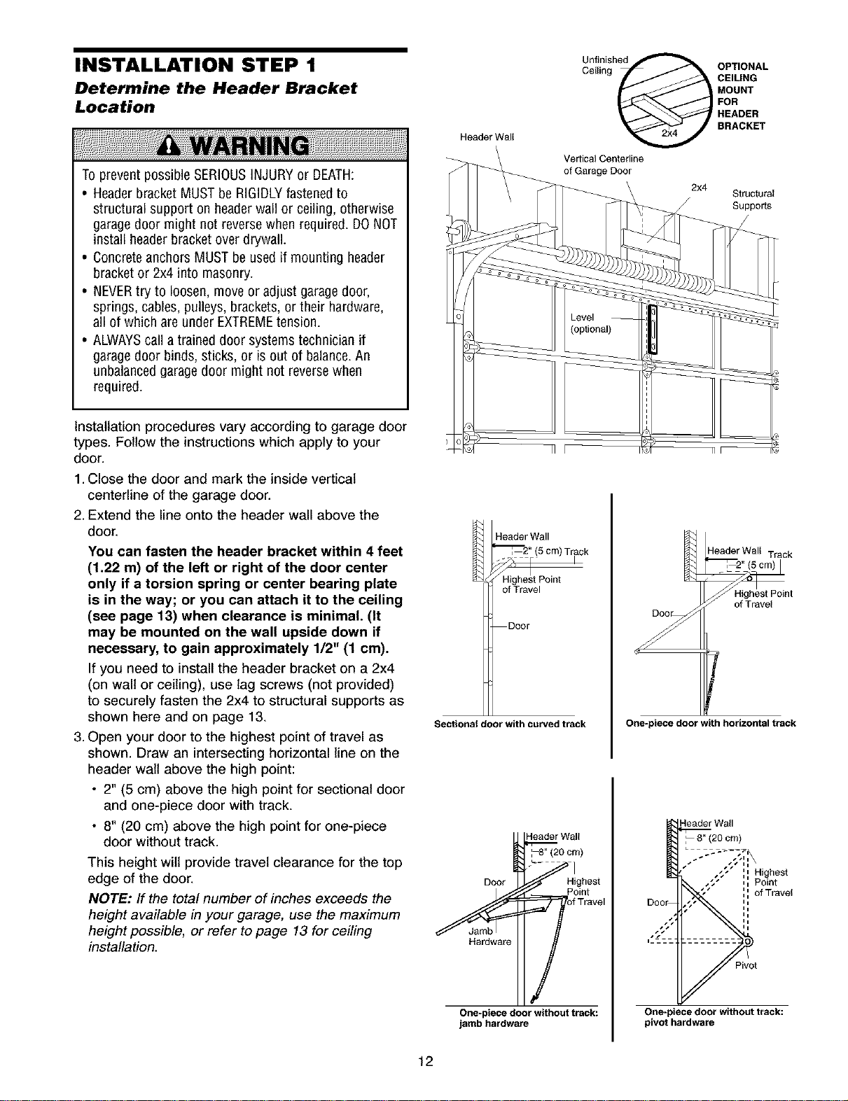
INSTALLATION STEP 1
Determine the Header Bracket
Location
To prevent possible SERIOUSINJURYor DEATH:
• Headerbracket MUST be RIGIDLYfastenedto
structural support on headerwall or ceiling, otherwise
garage door might not reversewhen required. DONOT
install header bracketover drywall.
• Concreteanchors MUST be used if mounting header
bracket or 2x4 into masonry.
• NEVERtry to loosen, move or adjust garage door,
springs, cables,pulleys, brackets, or their hardware,
all of which are under EXTREMEtension.
• ALWAYScall a trained door systems technician if
garage door binds, sticks, or is out of balance.An
unbalancedgaragedoor might not reversewhen
required.
Installation procedures vary according to garage door
types. Follow the instructions which apply to your
door.
1.Close the door and mark the inside vertical
centerline of the garage door.
2. Extend the line onto the header wall above the
door.
You can fasten the header bracket within 4 feet
(1.22 m) of the left or right of the door center
only if a torsion spring or center bearing plate
is in the way; or you can attach it to the ceiling
(see page 13) when clearance is minimal. (It
may be mounted on the wall upside down if
necessary, to gain approximately 1/2" (1 cm).
If you need to install the header bracket on a 2x4
(on wall or ceiling), use lag screws (not provided)
to securely fasten the 2x4 to structural supports as
shown here and on page 13.
3. Open your door to the highest point of travel as
shown. Draw an intersecting horizontal line on the
header walt above the high point:
• 2" (5 cm) above the high point for sectional door
and one-piece door with track.
• 8" (20 cm) above the high point for one-piece
door without track.
This height wilt provide travel clearance for the top
edge of the door.
NOTE: If the total number of inches exceeds the
height available in your garage, use the maximum
height possible, or refer to page 13 for ceiling
installation.
Header Wall
Vertical Centerline
of Garage Door
Header Wall
='_'_2" (5 cm) Track
of Travel
Door
Sectional door with curved track
Header Wall
p;oomj
Doer Highest
Ceilin OPTIONAL
g CEILING
MOUNT
FOR
Unfinishe_
HEADER
BRACKET
2x4
Structural
Suppods
Header Wall Track
Highest Point
0%e2 o,
Y
I7
One-piece door with horizontal track
Pivot
Highest
Point
of Travel
One-piece door without track:
jamb hardware
12
One=piece door without track:
pivot hardware
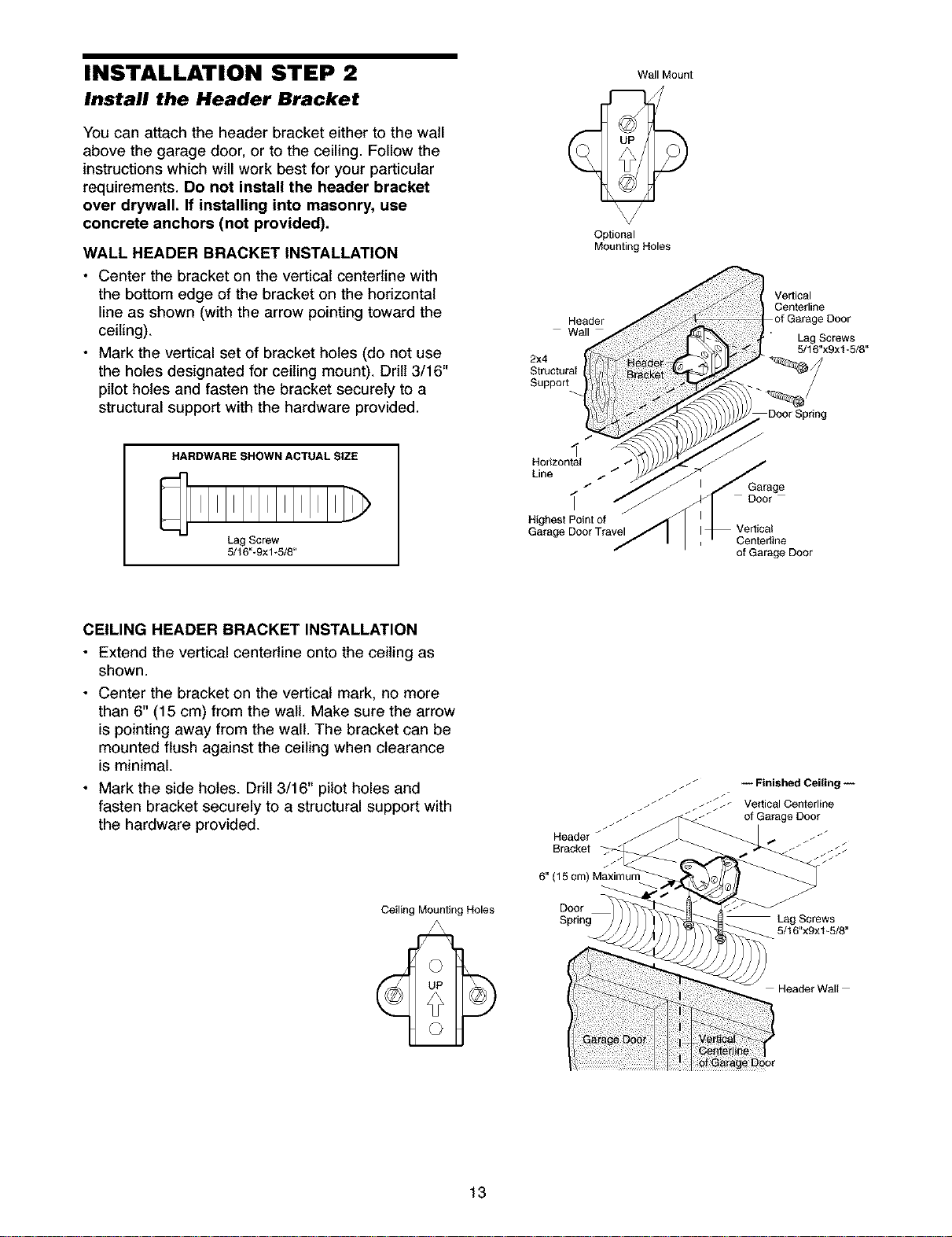
INSTALLATION STEP 2
Install the Header Bracket
You can attach the header bracket either to the wall
above the garage door, or to the ceiling. Follow the
instructions which will work best for your particular
requirements. Do not install the header bracket
over drywall. If installing into masonry, use
concrete anchors (not provided).
WALL HEADER BRACKET INSTALLATION
• Center the bracket on the vertical centerline with
the bottom edge of the bracket on the horizontal
line as shown (with the arrow pointing toward the
ceiling).
• Mark the vertical set of bracket holes (do not use
the holes designated for ceiling mount). Drill 3/16"
pilot holes and fasten the bracket securely to a
structural support with the hardware provided.
Optional
Mounting Holes
Header
Wall Mount
Vertical
Centedine
of Garage Door
Lag Screws
5/18"x9xl-5/8"
DoorSp#ng
HARDWARESHOWNACTUALSIZE
Lag Screw
5/16"-9xl-5/8"
CEILING HEADER BRACKET INSTALLATION
• Extend the vertical centerline onto the ceiling as
shown.
• Center the bracket on the vertical mark, no more
than 6" (15 cm) from the walt. Make sure the arrow
is pointing away from the wall. The bracket can be
mounted flush against the ceiling when clearance
is minimal.
• Mark the side holes. Drill 3/16" pilot holes and
fasten bracket securely to a structural support with
the hardware provided.
.- f:
Horizontal / /
Line
Highest Point of
Garage Door Travel
8" (15 cm) Maximum
/
/*
_ -- Finished Ceiling --
f_
/" -- _ Vertical Centerline
Header _
Bracket _
Garage
Door
Centerline
of Garage Door
of Garage Door
Ceiling Mounting Holes
13
Door
Sprin _ Lag Screws
5/16"xgx1-5/8"
Header Wall
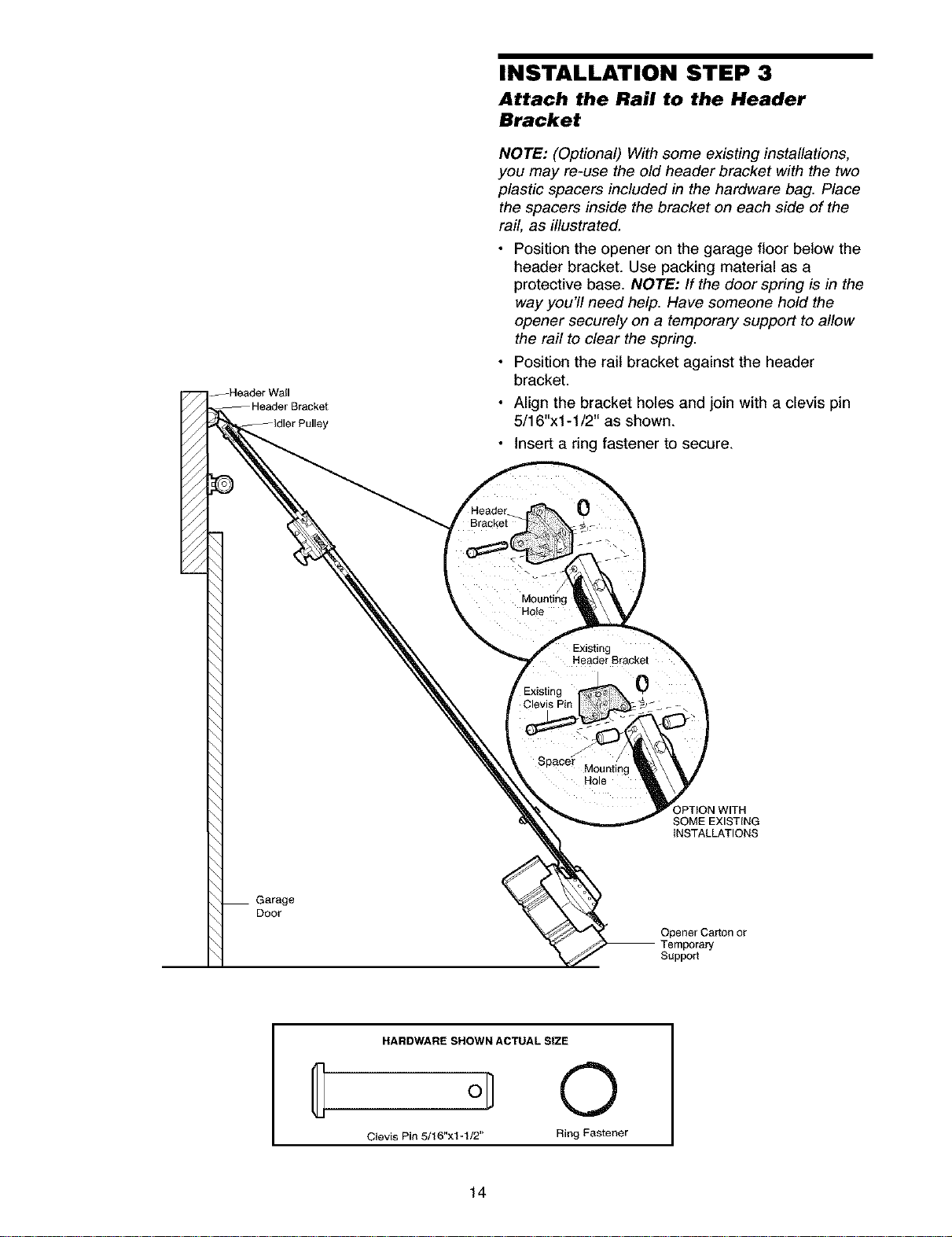
INSTALLATION STEP 3
Attach the Rail to the Header
Bracket
NOTE: (Optional) With some existing installations,
you may re-use the old header bracket with the two
plastic spacers included in the hardware bag. Place
the spacers inside the bracket on each side of the
rail, as illustrated.
Position the opener on the garage floor below the
header bracket. Use packing material as a
protective base. NOTE: If the door spring is in the
way you'll need help. Have someone hold the
opener securely on a temporary support to allow
the rail to clear the spring.
Position the rail bracket against the header
bracket.
Align the bracket holes and join with a clevis pin
5/16"xl-1/2" as shown.
Insert a ring fastener to secure.
Garage
Door
Mounting
Hole
Clevis
Spacer
HARDWARE SHOWN ACTUAL SIZE
Hole
OPTION WITH
SOME EXISTING
INSTALLATIONS
Opener Ca_on or
Temporary
Support
0
Clevis Pin 5/16"x1-1/2" Ring Fastener
14
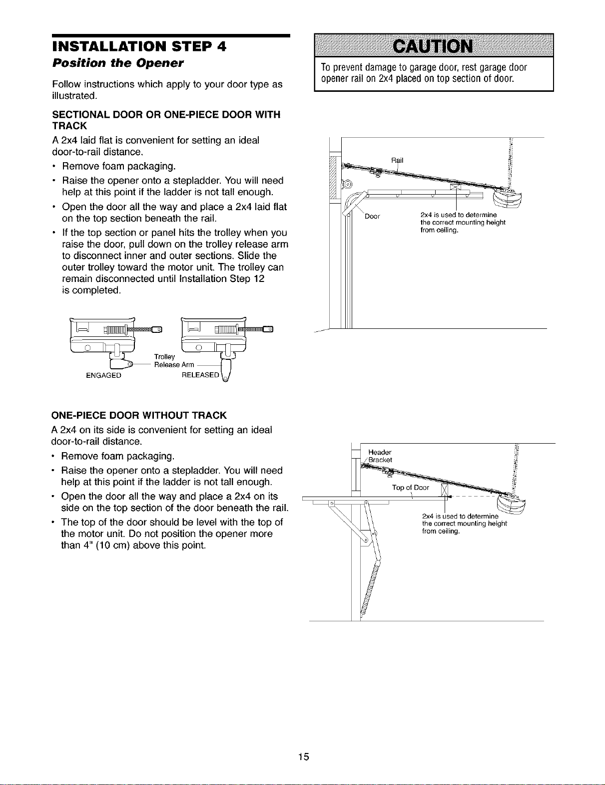
INSTALLATION STEP 4
Position the Opener
Follow instructions which apply to your door type as
illustrated.
SECTIONAL DOOR OR ONE-PIECE DOOR WITH
TRACK
A 2x4 laid flat is convenient for setting an ideal
door-to-rail distance.
• Remove foam packaging.
• Raise the opener onto a stepladder. You will need
help at this point if the ladder is not tall enough.
• Open the door all the way and place a 2x4 laid flat
on the top section beneath the rail.
• If the top section or panel hits the trolley when you
raise the door, pull down on the trolley release arm
to disconnect inner and outer sections. Slide the
outer trolley toward the motor unit. The trolley can
remain disconnected until Installation Step 12
is completed.
Toprevent damage to garage door, restgarage door
opener rail on 2x4 placedon top section of door.
ENGAGED
ONE-PIECE DOOR WITHOUT TRACK
A 2x4 on its side is convenient for setting an ideal
door-to-rail distance.
• Remove foam packaging.
• Raise the opener onto a stepladder. You will need
help at this point if the ladder is not tall enough.
• Open the door all the way and place a 2x4 on its
side on the top section of the door beneath the rail.
• The top of the door should be level with the top of
the motor unit. Do not position the opener more
than 4" (10 cm) above this point.
_Nea_e, ii
from ceiling.
_ the correct mounting height
15
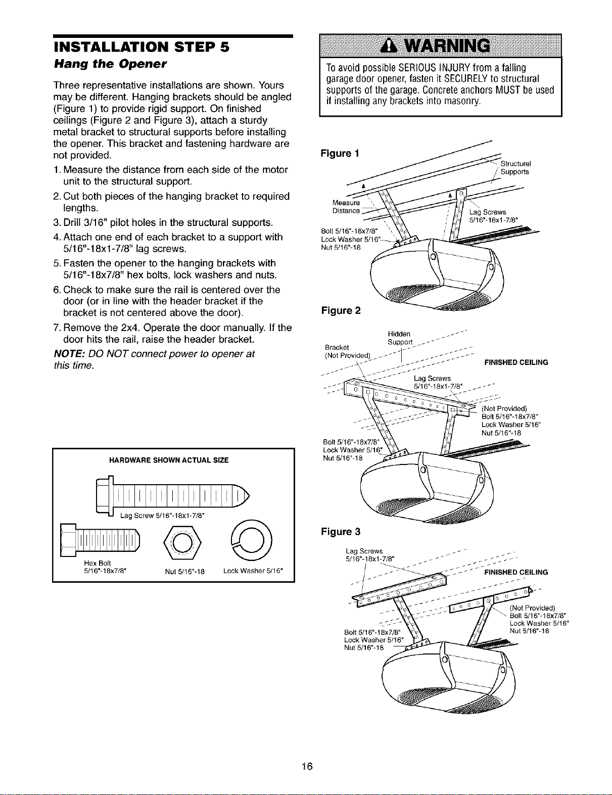
INSTALLATION STEP 5
Hang the Opener
Three representative installations are shown. Yours
may be different. Hanging brackets should be angled
(Figure 1) to provide rigid support. On finished
ceilings (Figure 2 and Figure 3), attach a sturdy
metal bracket to structural supports before installing
the opener. This bracket and fastening hardware are
not provided.
1. Measure the distance from each side of the motor
unit to the structural support.
2. Cut both pieces of the hanging bracket to required
lengths.
3. Drill 3/16" pilot holes in the structural supports.
4. Attach one end of each bracket to a support with
5/16"-18xl -7/8" lag screws.
5. Fasten the opener to the hanging brackets with
5/16"-18x7/8" hex bolts, lock washers and nuts.
6. Check to make sure the rail is centered over the
door (or in line with the header bracket if the
bracket is not centered above the door).
7. Remove the 2x4. Operate the door manually. If the
door hits the rail, raise the header bracket.
NOTE: DO NOT connect power to opener at
this time.
Toavoid possible SERIOUSINJURYfrom a falling
garage door opener,fasten it SECURELYto structural
supports of the garage.Concreteanchors MUSTbe used
if installing any brackets into masonry.
Figure 1
Suppods
Measure _
Distance
Bolt 5/16"- 18x7/6"
Nut 5/16"-16
Lag Screws
5/16"- 18xl -7/8"
Figure 2
FINISHED CEILING
HARDWARE SHOWN ACTUAL SIZE
©©
Hex Bolt
5/16"- 18x7/6"
Nut 5/16"q8 Lock Washer 5/16"
Lock Washer 6/16"
Nut 5/16"q8
Figure 3
Lag Screws
5/16"- 18xl _7/8"
Bolt 6/16"-18x7/8"
Lock Washer 5/16"
Nut 5/16"q8
(Not Provided)
BoIt 5/! 6"-18x7/6"
Lock Washer 5/16"
Nut 6/16"-18
(Not Provided)
Bolt 5/16"-18x7/8"
Lock Washer 5/16"
Nut 5/16"-16
16
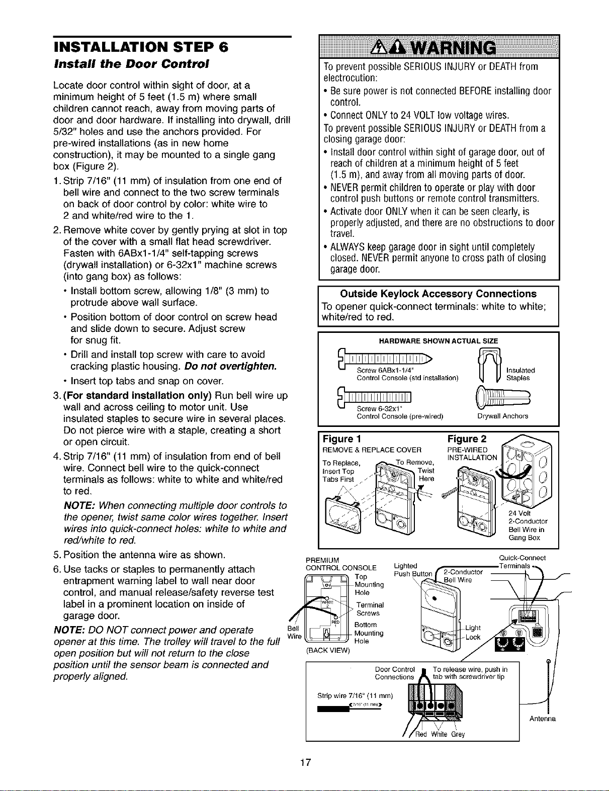
INSTALLATION STEP 6
Install the Door Control
Locate door control within sight of door, at a
minimum height of 5 feet (1.5 m) where small
children cannot reach, away from moving parts of
door and door hardware. If installing into drywall, drill
5/32" holes and use the anchors provided. For
pre-wired installations (as in new home
construction), it may be mounted to a single gang
box (Figure 2).
1. Strip 7/16" (11 mm) of insulation from one end of
bell wire and connect to the two screw terminals
on back of door control by color: white wire to
2 and white/red wire to the 1.
2. Remove white cover by gently prying at slot in top
of the cover with a small flat head screwdriver.
Fasten with 6ABx1-1/4" self-tapping screws
(drywall installation) or 6-32x1" machine screws
(into gang box) as follows:
• Install bottom screw, allowing 1/8" (3 mm) to
protrude above wall surface.
• Position bottom of door control on screw head
and slide down to secure. Adjust screw
for snug fit.
• Drill and install top screw with care to avoid
cracking plastic housing. Do not overtighten.
• Insert top tabs and snap on cover.
3. (For standard installation only) Run bell wire up
walt and across ceiling to motor unit. Use
insulated staples to secure wire in several places.
Do not pierce wire with a staple, creating a short
or open circuit.
4. Strip 7/16" (11 mm) of insulation from end of bell
wire. Connect bell wire to the quick-connect
terminals as follows: white to white and white/red
to red.
NOTE: When connecting multiple door controls to
the opener, twist same color wires together. Insert
wires into quick-connect holes: white to white and
red/white to red.
5. Position the antenna wire as shown.
6. Use tacks or staples to permanently attach
entrapment warning label to wall near door
control, and manual release/safety reverse test
label in a prominent location on inside of
garage door.
NOTE: DO NOT connect power and operate
opener at this time. The trolley will travel to the full
open position but will not return to the close
position until the sensor beam is connected and
properly aligned.
To prevent possible SERIOUSINJURYor DEATHfrom
electrocution:
• Be sure power is not connectedBEFOREinstalling door
control.
• Connect ONLYto 24 VOLTlow voltage wires.
To prevent possible SERIOUSINJURYor DEATHfrom a
closing garage door:
Installdoor control within sight of garage door, out of
reachof children at a minimum height of 5 feet
(1.5 m), and awayfrom all moving parts of door.
NEVERpermit children to operateor playwith door
control push buttons or remote control transmitters.
Activate door ONLYwhen it can be seen clearly, is
properly adjusted, and there are no obstructions to door
travel.
ALWAYSkeepgaragedoor in sight until completely
closed. NEVERpermit anyone to cross path of closing
garagedoor.
Outside Keylock Accessory Connections
To opener quick-connect terminals: white to white;
white/red to red.
Control Console (std installation) _]/ Yl_
Control Console (pre-wired) Drywall Anchors
Figure 1 Figure 2
TO Replace, To Remove, INSTALLATI
insert Top _ Twist _I
REMOVE & REPLACE COVER PRE*WIREDo_ IfT-_/'/li_
Tabs__First _ _ Here
PREMIUM
CONTROL CONSOLE Lighted
Top Push Button
Mounting
Hole
Terminal
Screws
Bell
Wire
(BACK VIEW)
Bottom
Mounting
Hole
HARDWARE SHOWN ACTUAL SIZE
Door Control
Connections
TO release wire, push in
tab with screwdriver tip
Insulated
Staples
24 Volt
2*Conductor
Bell Wire in
Gang Box
Quick-Connect
F
Strip wire 7/16" (11 mm)
17
(7/16 (11 r _nl))
J
Antenna
_ed White Grey
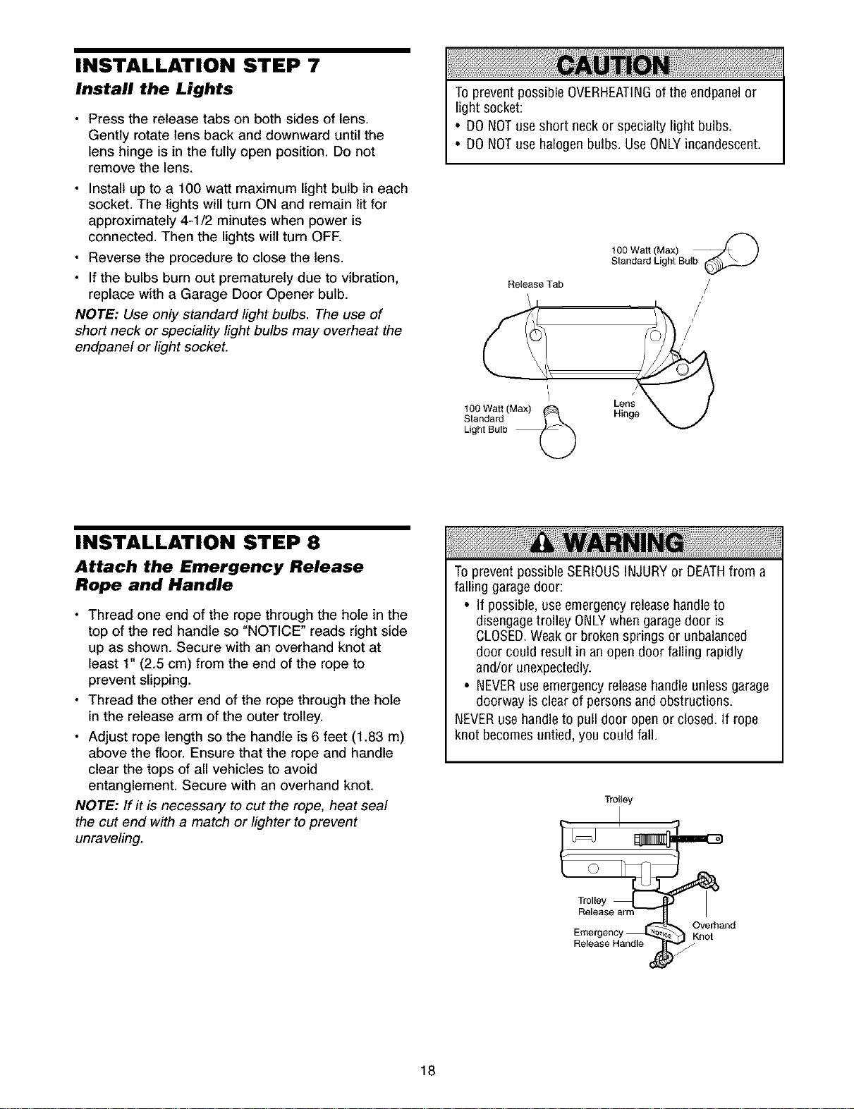
INSTALLATION STEP 7
Install the Lights
• Press the release tabs on both sides of lens.
Gently rotate lens back and downward until the
lens hinge is in the fully open position. Do not
remove the lens.
• Install up to a 100 watt maximum light bulb in each
socket. The lights will turn ON and remain lit for
approximately 4-1/2 minutes when power is
connected. Then the lights wilt turn OFR
• Reverse the procedure to close the lens.
• If the bulbs burn out prematurely due to vibration,
replace with a Garage Door Opener bulb.
NOTE: Use only standard light bulbs. The use of
short neck or speciality light bulbs may overheat the
endpanel or light socket.
To prevent possible OVERHEATINGof the endpanel or
light socket:
• DONOTuse short neck or specialty light bulbs.
• DONOTuse halogen bulbs. UseONLYincandescent.
1O0 Watt (Max)
Standard Light Bulb
Release Tab
INSTALLATION STEP 8
Attach the Emergency Release
Rope and Handle
• Thread one end of the rope through the hole in the
top of the red handle so "NOTICE" reads right side
up as shown. Secure with an overhand knot at
least 1" (2.5 cm) from the end of the rope to
prevent slipping.
• Thread the other end of the rope through the hole
in the release arm of the outer trolley.
• Adjust rope length so the handle is 6 feet (1.83 m)
above the floor. Ensure that the rope and handle
clear the tops of all vehicles to avoid
entanglement. Secure with an overhand knot.
NOTE: If it is necessary to cut the rope, heat seal
the cut end with a match or lighter to prevent
unraveling.
i,
1O0 Watt (Max)
Ught Bulb
Standard ___
ILenn__
Toprevent possible SERIOUSINJURYor DEATHfrom a
falling garage door:
• If possible, use emergency releasehandleto
disengagetrolley ONLYwhen garagedoor is
CLOSED.Weakor broken springs or unbalanced
door could result in an open door falling rapidly
and/or unexpectedly.
• NEVERuseemergency releasehandle unless garage
doorway is clear of personsand obstructions.
NEVERusehandle to pull door open or closed. If rope
knot becomes untied, you could fall.
Trolley
18
Edge°+ o 3 h°nd
Release Handle )_,
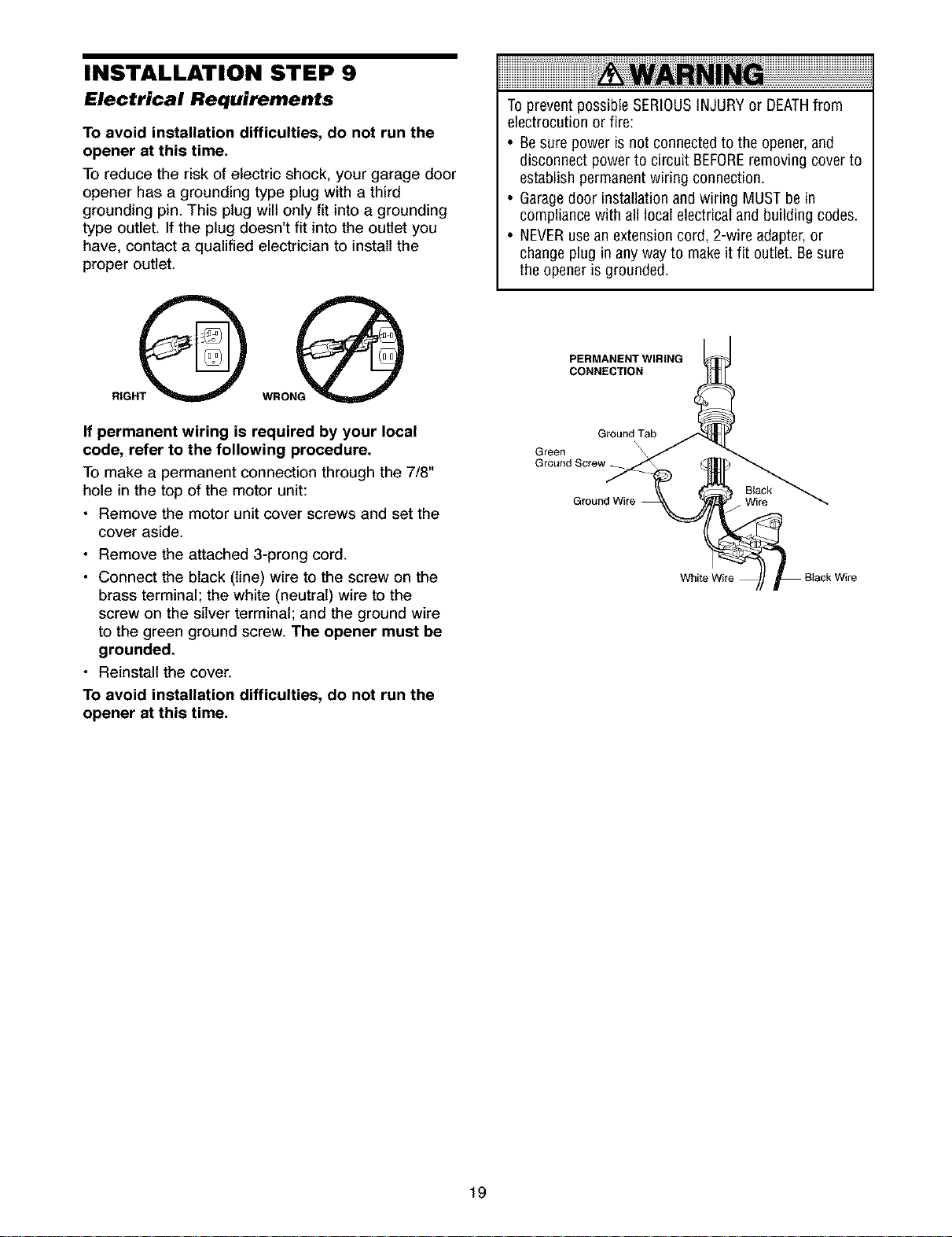
INSTALLATION STEP 9
Electrical Requirements
To avoid installation difficulties, do not run the
opener at this time.
To reduce the risk of electric shock, your garage door
opener has a grounding type plug with a third
grounding pin. This plug will only fit into a grounding
type outlet. If the plug doesn't fit into the outlet you
have, contact a qualified electrician to install the
proper outlet.
RIGHO
To prevent possible SERIOUSINJURYor DEATHfrom
electrocution or fire:
• Besure poweris not connectedto the opener,and
disconnect power to circuit BEFOREremoving cover to
establish permanent wiring connection.
• Garagedoor installation and wiring MUSTbe in
compliance with all local electrical and building codes.
• NEVERusean extension cord, 2-wire adapter, or
change plug in any way to make it fit outlet. Be sure
the opener is grounded.
PERMANENT WIRING
CONNECTION
If permanent wiring is required by your local
code, refer to the following procedure.
To make a permanent connection through the 7/8"
hole in the top of the motor unit:
• Remove the motor unit cover screws and set the
cover aside.
• Remove the attached 3-prong cord.
• Connect the black (line) wire to the screw on the
brass terminal; the white (neutral) wire to the
screw on the silver terminal; and the ground wire
to the green ground screw. The opener must be
grounded.
• Reinstall the cover.
To avoid installation difficulties, do not run the
opener at this time.
Green
Ground Screw
Ground Tab
\
Black
. Wire
White Wire
19
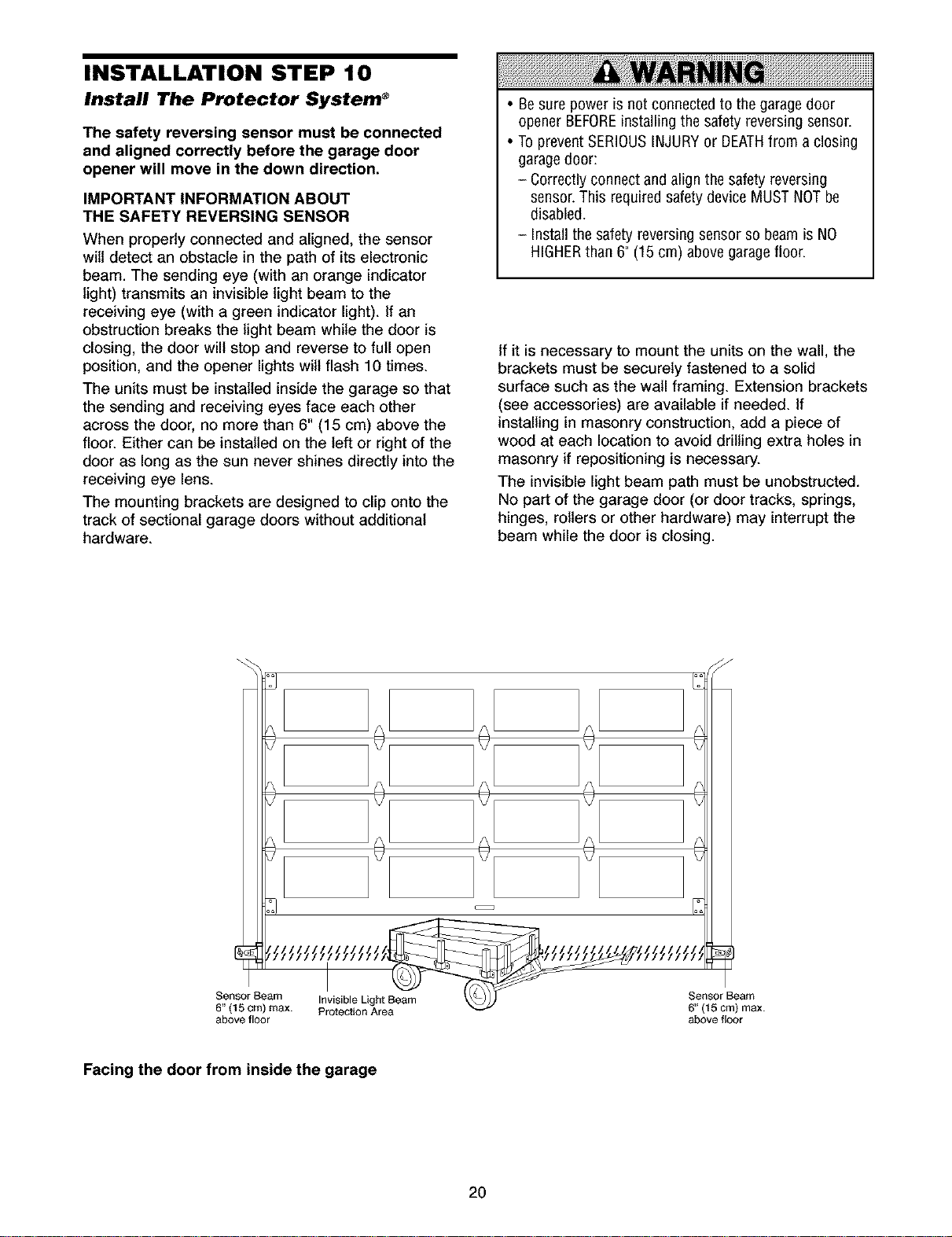
INSTALLATION STEP 10
Install The Protector System _
The safety reversing sensor must be connected
and aligned correctly before the garage door
opener will move in the down direction.
IMPORTANT INFORMATION ABOUT
THE SAFETY REVERSING SENSOR
When properly connected and aligned, the sensor
will detect an obstacle in the path of its electronic
beam. The sending eye (with an orange indicator
light) transmits an invisible light beam to the
receiving eye (with a green indicator light). If an
obstruction breaks the light beam while the door is
closing, the door will stop and reverse to full open
position, and the opener lights will flash 10 times.
The units must be installed inside the garage so that
the sending and receiving eyes face each other
across the door, no more than 6" (15 cm) above the
floor. Either can be installed on the left or right of the
door as long as the sun never shines directly into the
receiving eye lens.
The mounting brackets are designed to clip onto the
track of sectional garage doors without additional
hardware.
• Besure poweris not connectedto the garagedoor
opener BEFOREinstalling the safety reversing sensor.
• To prevent SERIOUSINJURYor DEATHfrom a closing
garagedoor:
- Correctly connect and align the safety reversing
sensor.This required safety device MUSTNOTbe
disabled.
- Installthe safety reversing sensor so beamis NO
HIGHERthan 6"(15 cm) above garage floor.
If it is necessary to mount the units on the wall, the
brackets must be securely fastened to a solid
surface such as the wall framing. Extension brackets
(see accessories) are available if needed. If
installing in masonry construction, add a piece of
wood at each location to avoid drilling extra holes in
masonry if repositioning is necessary.
The invisible light beam path must be unobstructed.
No part of the garage door (or door tracks, springs,
hinges, rollers or other hardware) may interrupt the
beam while the door is closing.
Sensor Beam Invisible Light Beam
6" (15 cm) max. Protection Area
above floor
Facing the door from inside the garage
2O
Sensor Beam
6" (I 5 cm) max.
above floor
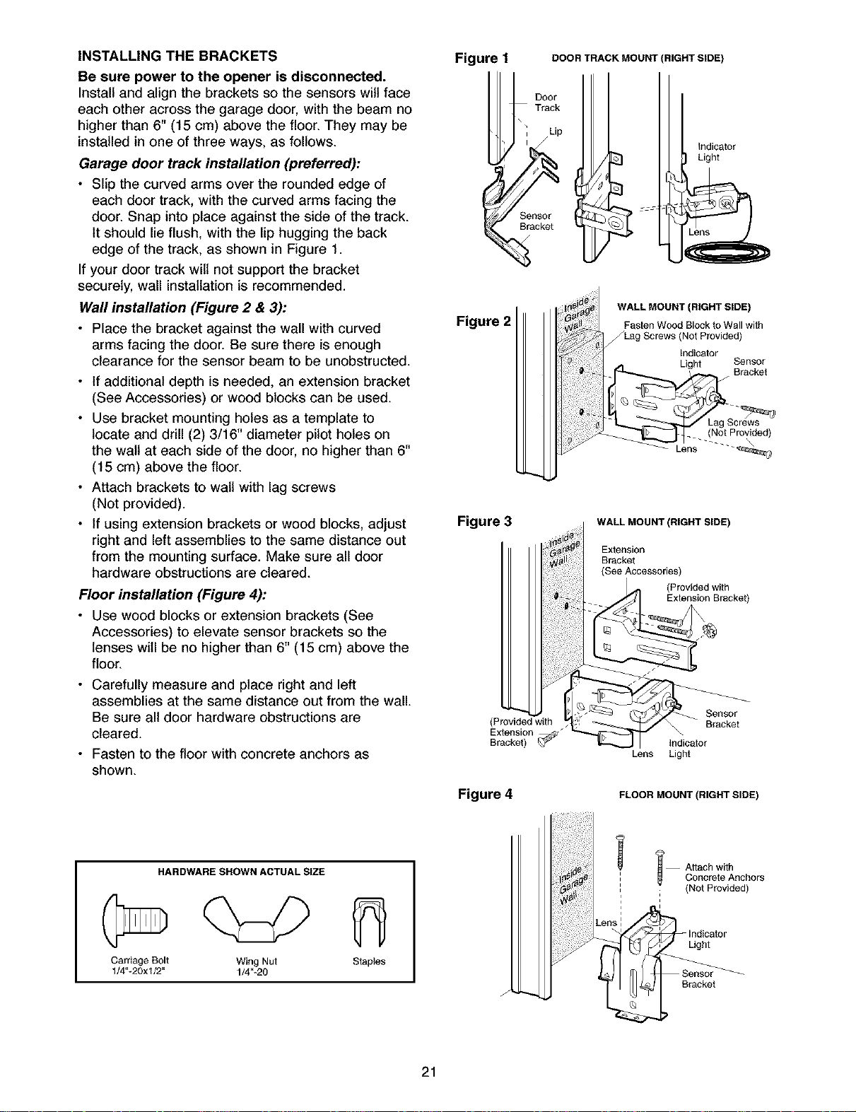
INSTALLING THE BRACKETS
Be sure power to the opener is disconnected.
Install and align the brackets so the sensors will face
each other across the garage door, with the beam no
higher than 6" (15 cm) above the floor. They may be
installed in one of three ways, as follows.
Garage door track installation (preferred):
• Slip the curved arms over the rounded edge of
each door track, with the curved arms facing the
door. Snap into place against the side of the track.
It should lie flush, with the lip hugging the back
edge of the track, as shown in Figure 1.
If your door track wilt not support the bracket
securely, wall installation is recommended.
Wall installation (Figure 2 & 3):
• Place the bracket against the wall with curved
arms facing the door. Be sure there is enough
clearance for the sensor beam to be unobstructed.
• If additional depth is needed, an extension bracket
(See Accessories) or wood blocks can be used.
• Use bracket mounting holes as a template to
locate and drill (2) 3/16" diameter pilot holes on
the walt at each side of the door, no higher than 6"
(15 cm) above the floor.
• Attach brackets to wall with lag screws
(Not provided).
• if using extension brackets or wood blocks, adjust
right and left assemblies to the same distance out
from the mounting surface. Make sure all door
hardware obstructions are cleared.
Floor installation (Figure 4):
• Use wood blocks or extension brackets (See
Accessories) to elevate sensor brackets so the
lenses will be no higher than 6" (15 cm) above the
floor.
• Carefully measure and place right and left
assemblies at the same distance out from the wall.
Be sure all door hardware obstructions are
cleared.
• Fasten to the floor with concrete anchors as
shown.
Figure I
Figure 2
Figure 3
DOOR TRACK MOUNT
I
BOOr
Track
Sensor
Bracket
RIGHT SIDE)
Indicator
Light
WALL MOUNT (RIGHT SIDE)
Fasten Wood Block to Wall with
/Lag Screws (Not Provided)
Indicator
Light Sensor
(Not Provided)
Lens
WALL MOUNT (RIGHT SIDE)
Extension
Bracket
(See Accessories)
Lens Light
Bracket
HARDWARESHOWNACTUALS_E
Carriage Bolt Wing Nut Staples
t/4"-20xt/2" 1/4"-20
21
Figure 4
FLOOR MOUNT (RIGHT SIDE)
i A_ach with
: (Not Provided)
Concrete Anchors
Light
B_c_t
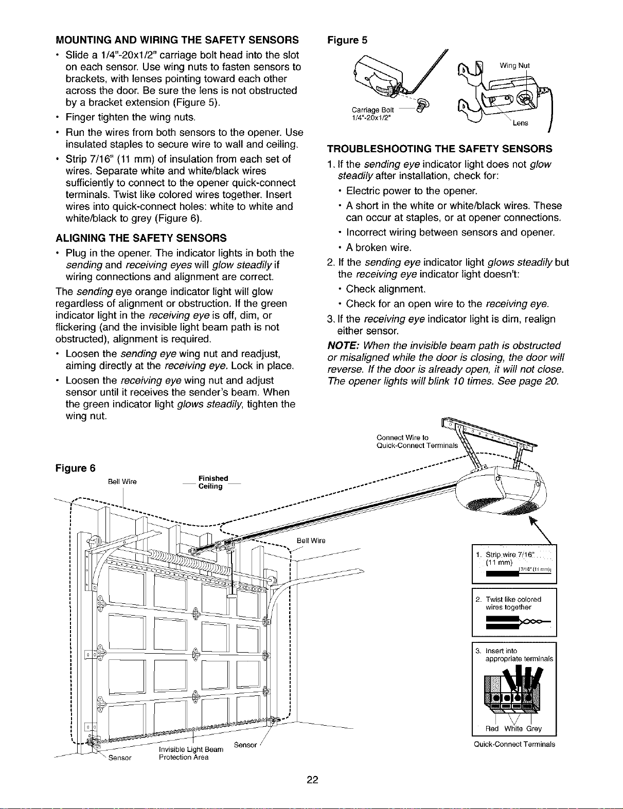
MOUNTING AND WIRING THE SAFETY SENSORS
• Slide a 1/4"-20xl/2" carriage bolt head into the slot
on each sensor. Use wing nuts to fasten sensors to
brackets, with lenses pointing toward each other
across the door. Be sure the lens is not obstructed
by a bracket extension (Figure 5).
• Finger tighten the wing nuts.
• Run the wires from both sensors to the opener. Use
insulated staples to secure wire to wall and ceiling.
• Strip 7/16" (11 mm) of insulation from each set of
wires. Separate white and white/black wires
sufficiently to connect to the opener quick-connect
terminals. Twist like colored wires together. Insert
wires into quick-connect holes: white to white and
white/black to grey (Figure 6).
ALIGNING THE SAFETY SENSORS
• Plug in the opener. The indicator lights in both the
sending and receiving eyes will glow steadily if
wiring connections and alignment are correct.
The sending eye orange indicator light will glow
regardless of alignment or obstruction. If the green
indicator light in the receiving eye is off, dim, or
flickering (and the invisible light beam path is not
obstructed), alignment is required.
• Loosen the sending eye wing nut and readjust,
aiming directly at the receiving eye. Lock in place.
• Loosen the receiving eye wing nut and adjust
sensor until it receives the sender's beam. When
the green indicator light glows steadily, tighten the
wing nut.
Figure 5
Carriage Bolt -"_
1/4"-20xl/2"
TROUBLESHOOTING THE SAFETY SENSORS
1. If the sending eye indicator light does not glow
steadily after installation, check for:
• Electric power to the opener.
• A short in the white or white/black wires. These
can occur at staples, or at opener connections.
• Incorrect wiring between sensors and opener.
• A broken wire.
2. If the sending eye indicator light glows steadily but
the receiving eye indicator light doesn't:
• Check alignment.
• Check for an open wire to the receiving eye.
3. If the receiving eye indicator light is dim, realign
either sensor.
NOTE: When the invisible beam path is obstructed
or misaligned while the door is closing, the door will
reverse. If the door is already open, it will not close.
The opener lights will blink 10 times. See page 20.
Figure 6
Bell Wire
_ensor invisible Light Beam
Protection Area
Finished
Ceiling
Sensor f
Bell Wire
Connect Wire to
Quick-Connect Terminal
2. Twist like colored
wires together
3. insert into
appropriate terminals
Red White (
Quick-Connect Terminal
22
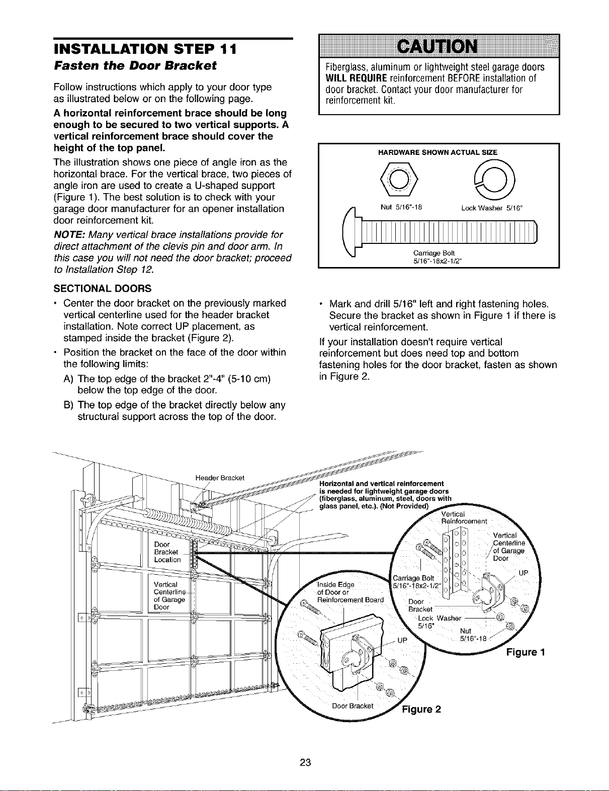
INSTALLATION STEP 11
Fasten the Door Bracket
Follow instructions which apply to your door type
as illustrated below or on the following page.
A horizontal reinforcement brace should be long
enough to be secured to two vertical supports. A
vertical reinforcement brace should cover the
height of the top panel.
The illustration shows one piece of angle iron as the
horizontal brace. For the vertical brace, two pieces of
angle iron are used to create a U-shaped support
(Figure 1). The best solution is to check with your
garage door manufacturer for an opener installation
door reinforcement kit.
NOTE: Many vertical brace installations provide for
direct attachment of the clevis pin and door arm. In
this case you will not need the door bracket; proceed
to Installation Step 12.
SECTIONAL DOORS
• Center the door bracket on the previously marked
vertical centerline used for the header bracket
installation. Note correct UP placement, as
stamped inside the bracket (Figure 2).
• Position the bracket on the face of the door within
the following limits:
A) The top edge of the bracket 2"-4" (5-10 cm)
below the top edge of the door.
B) The top edge of the bracket directly below any
structural support across the top of the door.
Fiberglass,aluminum or lightweight steel garagedoors
Will. REQUIREreinforcement BEFOREinstallation of
door bracket. Contactyour door manufacturer for
reinforcement kit.
HARDWARE SHOWN ACTUAL SIZE
G ©
Nut 5/16"-18 LockWasher 5/16"
Carriage Bolt
5/16"-18x2-1/2"
• Mark and drill 5/16" left and right fastening holes.
Secure the bracket as shown in Figure 1 if there is
vertical reinforcement.
If your installation doesn't require vertical
reinforcement but does need top and bottom
fastening holes for the door bracket, fasten as shown
in Figure 2.
Horizontal and vertical reinforcement
is needed for lightweight garage doors
(fiberglass, aluminum, steel, doors with
23
Figure 1
ure 2
 Loading...