

Page 1
Owner’s
Manual
Model No.
139.53662SRT
139.5367SSRT
For Residential Use
Only
CRAFTSMAN^
Caution:
Read and follow all
safety rules and
operating instructions
before first use of this
product.
Fasten the manual
near the garage door
after installation.
GARAGE DOOR OPENER 1/2 HP
@ Safety Precautions
и Assembly
Ш Installation
a Adjustment
a Care and Maintenance
m Operation
m Troubleshoc^tji^^'i;
H Parts List
Complies wilii UL 325 /^1 li \
refiiiations effective I )
Januaiy 1, t993
Sears, Roebuck and Co., Hoffman Estates, IL 60179 U.S.A.
Page 2
Contents
A review of safety alert symbols
Youll need tools
Safety information reqardinq qaraqa door
locks and ropes
Testing your garage door for sticking,
binding and balance
Illustration of sectional door instailadQn ....
Illustration of one-piece door installation...
Carton inventory...................
Hardware inventory.....................
Assembly section - pages 8 -11
Assemble T-raiL...
Attach cable pulley bracket............
Install trolley
Fasten T-rai! to opener...................
install chain/cabie
Attach sprocket cover.,,.,.
Tighten the chain and cable
Installation section * pages 11-27
Installation safety instructions..__....
Determine header bracket location
Sectional door ...........,
One-piece door,.,..
Install the header bracket
Attach the T-ral to header bracket
Position the opener
Hang the opener............................
Install the door control
...........................................
.........
....
.....
.
.......
..................
.........
........................
...................
............
.........
.....
.........
.
......
................
..
.
.
Page
.....
___4
......5
......7
.
.....
...10
™10
,..11
,...11
....12
.13
.....
14
......15
......
16
......17
.....
.18
3
.6
9
Corrients
.
___ig
„..,...19
.......
.....
.
,.22,23
........24
.
......
........26
„„....27
........28
.
......29
........
....... .^10
........31
____
.
........
.„.„..32
____
..34,35
........36
........37
.„....,39
........
........40
Install the lights and lenses...,..............
Attach emergency release rope and handle „
F*lcu'''ÍTir't3i f'oni ti rs3mí3rsic
t«№lvtrwUi « Bv.|wl E iB I ItiO • >11^ nn-. Kirn*, ,no»FT,r'.Vr<t ■'|‘I T , f ,
Safety reversing sensor information
Install the safety reversing sensor
i—iscrtcsn í*ír*i/^í*
i cUaLcíi i UwvJi Ul i-cil tiJwVJi I
Fasten door bracket (one-piece door)
Connect door arm to trolley (sectional door)
Connect door arm to trolley (one-piece door).
Adjustment section - pages ^ - 30
Travel limit adjustments ...............................
Force adjustments............................................
Test the safety reversing serrsor...........
Test the safety reverse system
Operation safety instructions............................
Care of your opener ............................................
Maintenance schedule
Operation of your opener ............................
Receiver and remote control programming ......
Having a problem?...
Repair parts, rail assembly
Repair parts, installation...,
Repair parts, opener assembly
Accessories
Index..........................
How to order repair parte
Maintenance agreement
Warranty.............
.......................................
...........................................
________________
..
.........
...........................
.............
.
.
.................
.
Page
20
,.21
25
30
31
31
33
36
38
40
40
Start by Reviewing these Important Safety Alert Symbols
When you see these Safety Symbols on the following pages, they will alert you to the possibility of
serious Injury or death if you do not compiy with the corresponding instructions. The hazard may
come from something mechanical or from electric shock. Head the instructions carefully.
ÉñechmTi©all)4iA.7. cj
When you see^this sSf^^Symb^l-On the following pages, it will alert you to the possibility of damage
■dxLygur garage'3o”0T anti/oli the garage tioor opener if you do not comply with the corresponding
instriiction'SrHead.ifte^msfruc|/OTdcarefui/^^
This garage door opener is designed and tested to offer safe service provided it is installed, operated,
maintained and tested in strict accordance with the safety instructions contained in this manual.
Electrical
Page 3
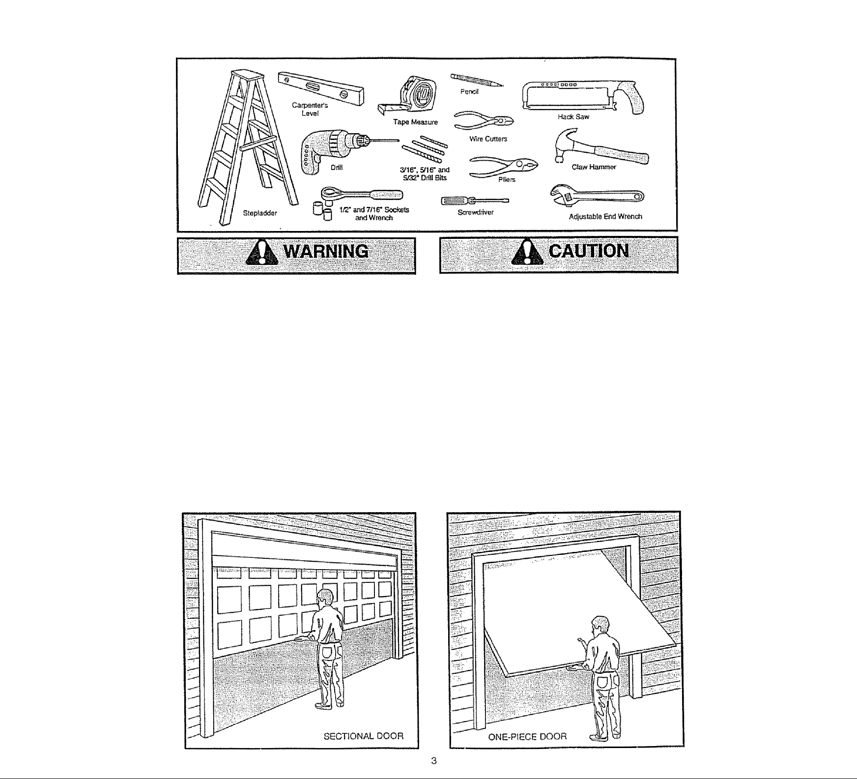
You'll Need Tools
During assembiy, instaliation and adjustment of the opener, instructions wili cail for hand ioois shnwrs below.
An unbalanced garage door might not reverse
when required and someone under the door
could be seriously injured or killed.
If your garage door binds, sticks or is out of
balance, caii for professionai garage door
service. Garage doors, door springs, cables,
pulleys, brackets and their hardware are under
extreme tension and can cause serious injury
or death. Do not try to ioosen, move or adjust
them yourself!
Bopes left on a garage door could cause
someone to become entangled and killed.
Remove ail ropes connected to the door before
installing and operating the opener.
Identify the type and height of your door and any
special conditions that exist and any additional
materials that may be required by referring to the lists
on page 4 or page 6.
To avoid damage to the garage door and
opener, disable locks before Installing and
operating the opener. Use a wood screwr or nail
to hold locks in the "open" (unlocked)
position.
Operation at other than 120V 60 Hz will cause
opener malfunction and damage.
Before you begin, complete the following test to
make sure your door is balanced, and is not
sticking or binding:
• Lift the door about halfway as shown. Release the
door, it should stay in place, supported entirely by
its springs.
• Raise and lower the door to see if there is any
binding or sticking. •
Page 4
Before you begin, survey your garaoe area to
see whether any of the conditions fallow apply
to your installation.
^ Hofizofita] and vafiicsii reintotcameni
is needed for fighiweigW garage doors
¡fibergiass, stesi, aluminum, door
wtBi glass panels, etc.).
See page 24 for details.
Based on your particular requirements, there are
sever^ installation steps which might call for
materiaJs and/or hardware not included in the carton
* Step 1, page 12 - Look at the wail or ceiling above
the garage door. The header bracket must be
securely fastened to structural supports.
■ Step 5, page 17 ~ Do you have a finished ceiling in
your garage? It so, a support bracket and
additionai fastening hardware may be required.
‘ Safety reversing sensor, page 21 - Depending
upon garage construction, wood blocks may need
to be fastened to mounting locations before
sensors are Installed.
' Step 10, page 22 - Alternate floor mounting of the
safety reversing sensor will require hardware not
provided.
■ Step 11, page 24 - Do you have a steel, aiuminum,
fiberglass or glass pane! door? If so, horizontal
and vertical reinforcement is required.
* Look at the garage door where it meets the floor.
It must close on the floor ail the way across.
Otherwise, the safety reverse system may not
work properly. See page 30. Roor or door should
be repaired.
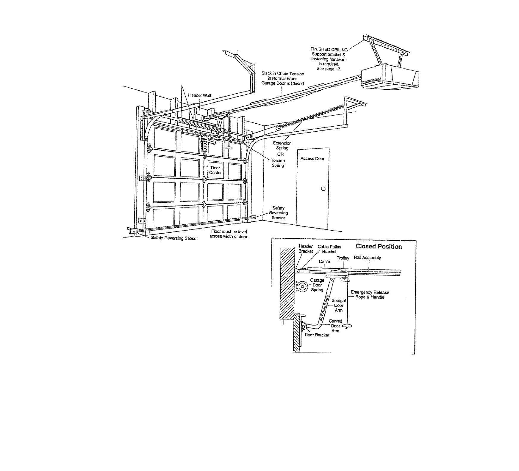
Hsadsf
Willi
Garage -
Door
* TTie opener can be fnstalied within 2 feet to the left
or right of the door center if there is a torsion spring
or center bearing plate In the way of the header
bracket or door bracket area. If your door has
extension springs, the opener must be installed
in the center of the door. See pages 12 and 24.
> Do you have an access door in addition to the
garage door? if not. Mode! 53702 Emerqencv
Key Release is required. See page 38.
■ if your door is more than 7 feet high, see the raíl
extension kits listed on page 38,
You may find it helpful to refer back to this page as you proceed with the installation of your opener.
Page 5
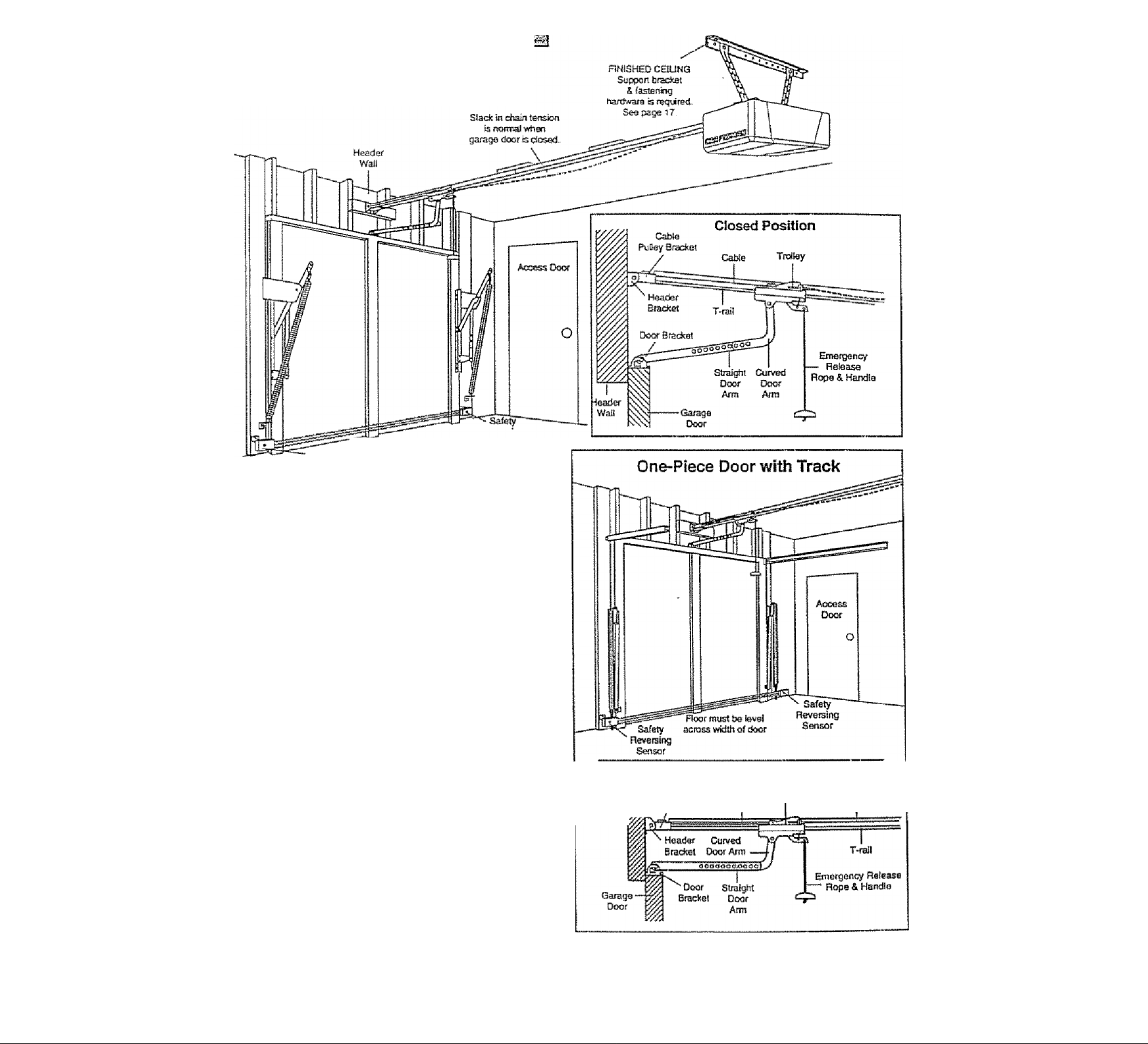
i :,,CiQN E'PiH©Es00Qiilia§ta|№iil
Be'fore you begin, survey your garage area to
see whether any of the conditions below apply
to your installation.
One-Piece Door without Track
'Esp between Hoor and boBom Sensor
Safely of door must not eiOeed 1 /4*.,
Reversing Sensor
Based on your particuiar requirements, there are
several installation steps which might caJl for
materials and/or hardware not included in the carton.,
• Step 1, page 13 - Look at the wall or ceiling above
the garage door. The header bracket hicsf be
securely fastened to struciuial supports,
• Step 5, page 17 - Do you have a finished ceiling in
your garage? If so, a support bracket arrd
additional fastening hardware (not supplied) may
be required.
• Safety reversing sensor, page 21 - Depending on
garage constmction, wood blocks may need to be
securely fastened to mounting locations before
sensors are installed.
• Step 10, page 22 - Alternate floor mounting of the
safety reversing sensor will require hardware that
is not provided.
• Step 11, page 25 - Generally, a one-piece door
does not require reinforcement. If your door is
lightweight, you can refer to the information
relating to sectional doors on page 24.
• Step 11, page 25 - Depending on your door's
constmctlon, you might need additional mounting
hardware for the door bracket.
• Do you have an access door in addition to the
garage door? If not, Model 53702 Emergency Key
Release is required. See page 38.
• The gap between the bottom of the garage
door and the floor cannot exceed 1/4".
Otherwise, the safety reverse system may not
work properly. See page 30. The floor or the door
should be repaired.
Reverang
Closed Position
Headar — w PuHey Brackai
Gabte
Cable
Gbain
Was
You may find it helpful to refer back to this page
as you proceed with the installation of your
opener.
Page 6
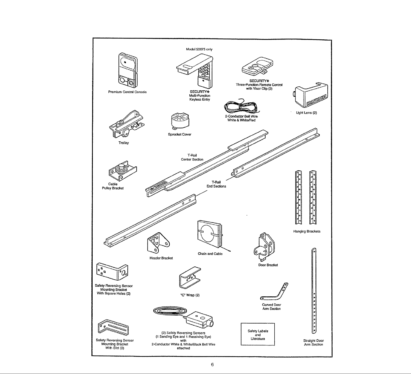
Carton Inventory
Your garage door opener is packaged in two cartons which contain aii parts illustiated below. If anything is
missing, carefully check the packing material. Parts may be ‘stuck* in the foam. Hardware for assembly and
installation is shown on page 7,
Page 7
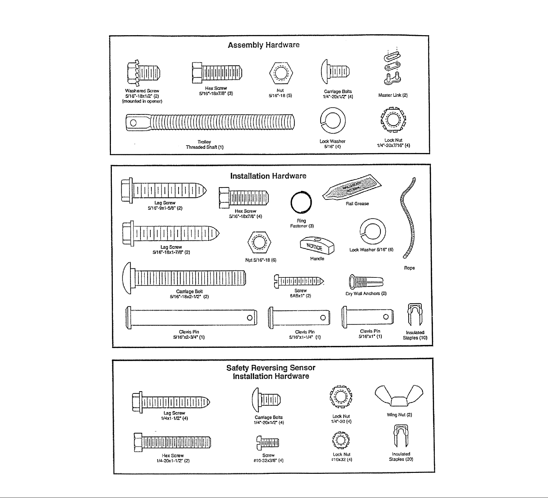
Separate all hardware from the packages in the rail carton and the opener carton, as
shown below, for the assembly and installation procedures.
Page 8
Assembly Section: Pages 8-11
To avoid installation difficulties, do not run the garage door opener until Instructed to do so.
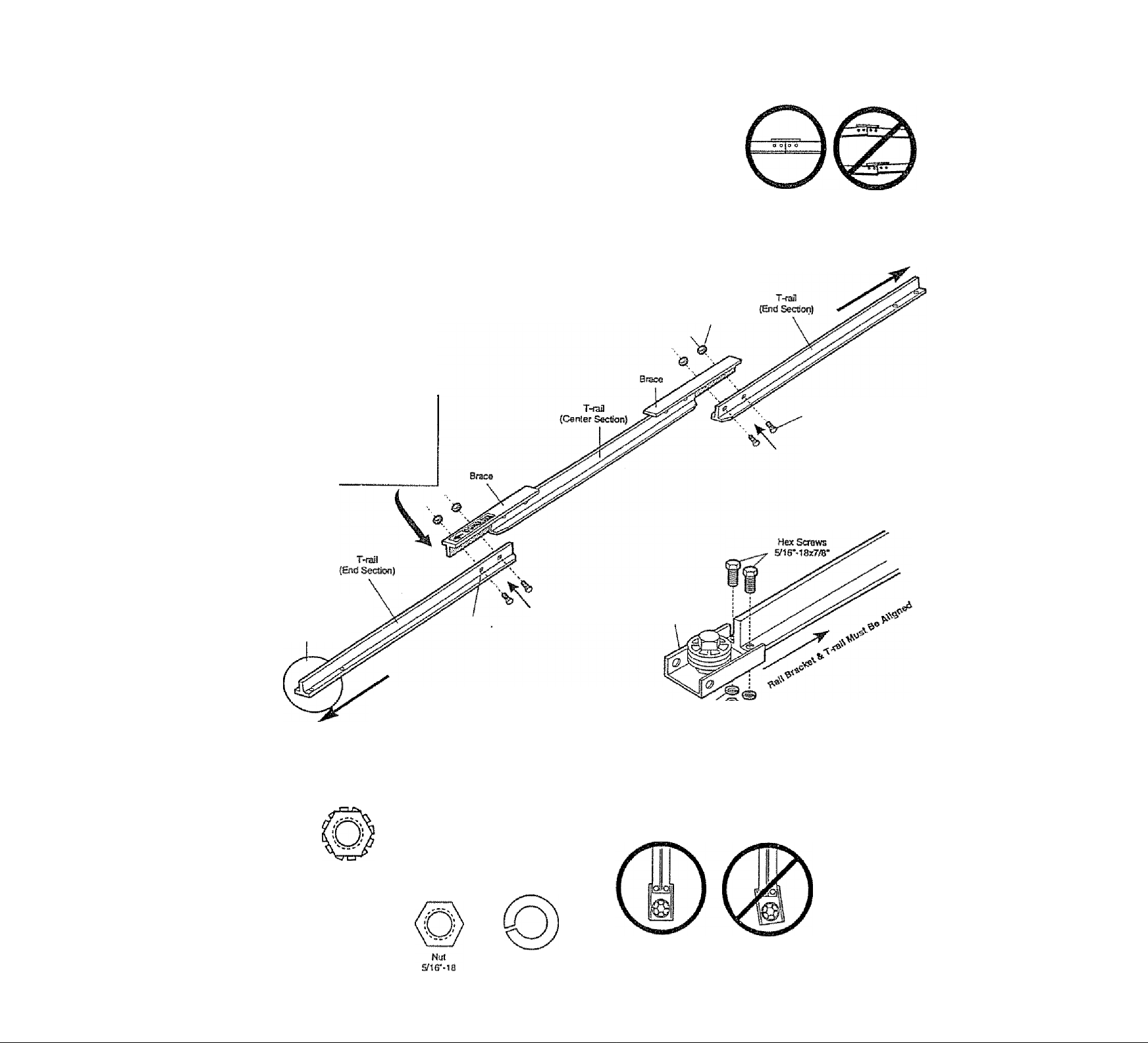
Assembly Step 1
Assemble the T-rail &
Attach the Cable Pulley Bracket
* Place the 3 T-rail sections on a flat surface for
assembly. The end sections are idenficai. Make
sure the "arrow label" on the center section is
pointing toward the door.
• Insert the carriage bolts so the square boit necks
seat in the square holes in the T-rafI end sections
and pass through the round holes in T-rafi center
section. Assemble lock nuts, ensure alignment and
tighten.
If T-raii is not assembled
EXACTLY as shown,
trolley Will not travel
smoothly along length of
rail or It will hit against
the nuts.
Make sure bait necks are
seated In the square
holes and rails are
aligned before you
tighten lock nuts. (See
right and wrong views).
Improper assembly can
E^use jerky troJIey
operation, noise and/or
nuisance door reversals.
1M* Look Nu!
T-RAlLaACK
(Tooparsî)
Carnage Soit
Wrong
Cabio pulley bracket
attaches lo f^ONT
dl'lli« Ul I (cUt
Hardware Shown Actual Size
Lock Nut
1M*-20xr/16*
Hex Screw
stir-iaxT/B"
T-RAIL FRONT
(TO OOOR)
Square Carnage
Bolt Holes
Catiiage Bolts
Lock Washer
5/1 g-
Cable FuUey
Bracket
Lock Washer © 0..,
S/16' > !
SiW
► Position the rable pulley bracket on the tont end of the
T-rail as shown. Fasten securely with the hardware.
When
tightening the
screws, be
sure to keep
bracket parallel
to the rail.
Otherwise, the
rail may bow
Right
Wrong
when opener is
opsrstsd.
Page 9
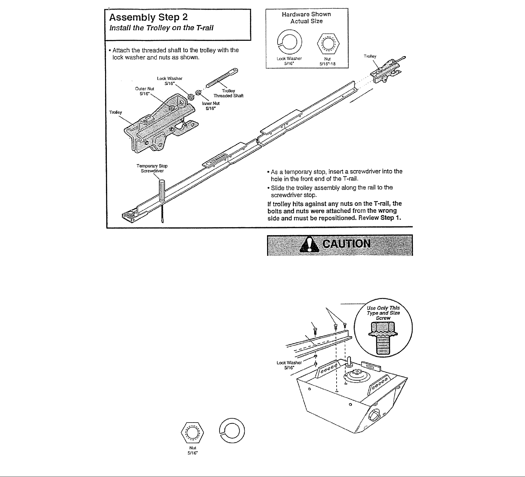
Assembly Step 3
Fasten the T-rail to the Opener
• Place the opener on packing material to protect
the cover. For convenience, put a support under
the cable pulley bracket
• Remove the (2) 5/16"-18x1/2* washered screws
mounted in the top of the opener.
• Align the holes in the back section of the T-raii with
the holes in the opener,
• Fasten the rati with the (2) washered screws
previously removed, tighten securely.
Ftemember to use only these screws! Any other
screws will cause serious damage to the opener.
• Insert a S/16“-18x7/8* hex screw into the cover
protection bolt hole in the T-rail as shown. Tighten
securely with a 5/16" lock washer and nut
NOTE: This screw prevents trolley over-travel.
Keep a 2“ minimum between the trolley and this
screw when adjusting travel limits {see page 28).
Hardware Shown Actual Size
To fasten rail, use only those screws mounted
in the top of the opener. Any other screws will
cause serious damage to the opener.
Washered Screw
S/IS’-iaxt/r
Hex Screw
5/16*-1Sx7/B'
Cover
Protecijon
Bolt Hole
T-raB
{Sack Section)
Nut
S/16*-18
Hex Screw
S/)6'-iax7/8*
Lock Washer
S/16*
Page 10
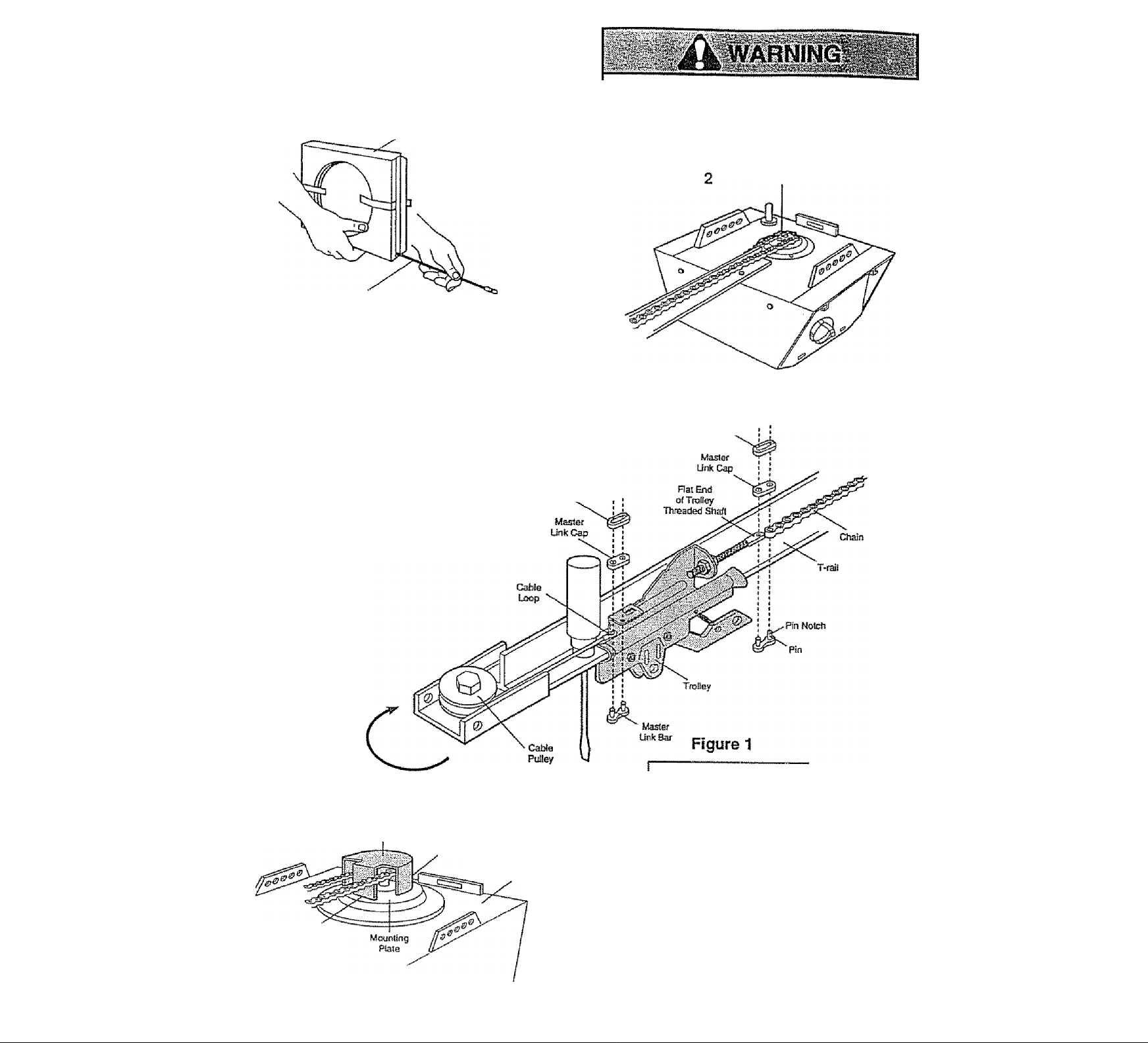
Assembly Step 4
install the Chain/Cable &
Attach the Sprocket Cover
Dispensing Carton
Leava Chain and Cable
inside OispensETsg
Carton to Prevail Kjnidng.
Keep Chain and Cabla
Tay| When Dispensing
• Detach the cable loop from the carton and fasten It
to the trolley with a master link from the hardware
bag. See master link procedure, Rgure 1.
• yyith the trolley against the screwdriver, dispense
the cable around the pulley.
® Proceed back around the opener sprocket,
Rgure 2, Be sure sprocket teeth engage the chain.
Continue forwant to the trolley threaded shaft,
Rgure 3.
• Use the second master link to connect the
chain to the flat end of the shaft Check
to make sure the chain is not
twisted.
" Remove the screwdriver.
DipOn Spring
Master Unk
Serious Infury can resuit If fingers become
entangled in moving opener sprocket. Attach
sprocket cover securely. Never operate opener
while your hand Is near the opener sprocket.
Opener
Figure
Spfodtat
Figure 3
MasierUnic
Ciip-On Spring
Frani Tab Slot
Instait Cha'n teid Cabla
in This Direction
Sprocket
Cover
Back Tab Slot
Top of Qpenar
Master Link Procedure;
Push pifis of raasier link bar
through cable loop and ho!e in
front end of troiley. Posh rap
over pins and past notchesSlide clip-on spring over cap
and into notches until both
pins are securely tocked.
To attach the sprocket cover:
• Insert the back tab in the opener slot. Squeeze the
cover slightly and insert the front tab in the slot on
the mounting plate.
10
Page 11
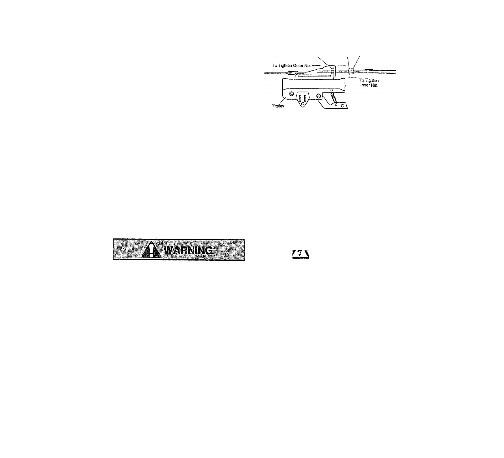
Assembly Step 5
Tighten the Chain & Cable
* Spin the inner ntft and lock washer down the
threaded shaft, away from the troiley.
* To tighten the chain, turn outer nut in the direction
shown. As you turn the nut, keep the chain
from twisting.
* When the chain is approximately 1/2' above the
base of the T-raii at its midpoint, re-tighien the
inner nut to secure the adjustment
Sprocket noise can result if chain Is either too
loose or too tight
When instaJlation is complete, you may notice some
chain droop with the door closed. This is normal. If
the chain returns to the position shown when the
door is open, do notre-adjust the chain.
NOTE: During future maintenance, ALWAYS
pull the emergency release handle to disconnect
trolley before adjusting chain.
Otrte/ Nut Wa^fier
~i ГТ T t I
Lock
Chain
ia Inch
i
O* I "TBlf
You have now finished assembling your garage door opener. Please read the following warnings before proceeding to the installation section;
IMPORTANT INSTALLATION INSTRUCTIONS
> “ , ■ у #c\
/V
WARNING
To reduce the risk of severe injury or death to persons:
1. READ AND FOLLOW ALL INSTALLATiON INSTRUCTIONS.
2. install only on a properly balanced and lubricated garage door. An improperly balanced door
may not reverse and could result in severe injury or death. Repairs to cables, spring assemblies
and other hardware must be made by a professional service person before installing opener.
3. Disable all locks and remove all ropes connected to the garage door before installing the opener.
Ropes connected to a garage door can cause entanglement and death.
4. If possible, install door opener 7 feet or more above floor with the emergency release handle
mounted 6 feet above the floor.
5. Do not connect the opener to power source until instructed to do so,
6. Locate the Door Control within sight of the door at a minimum height of 5 feet where small
children cannot reach, and away from ail moving parts of the door,
7. Install the User Safety Instruction Label on the wall adjacent to the door control and the
Maintenance Instruction Label in a prominent location on the inside of the garage door.
8. Upon completion of the installation, the door must reverse when it comes in contact with a
one-inch high object or a 2x4 laid flat on the floor.
9. Do not wear watches, rings or loose clothing while installing or servicing an opener. Jewelry or
loose clothing can be caught in the mechanism of the garage door or the opener.
11
Page 12
Installation Section: Pages 12 - 27
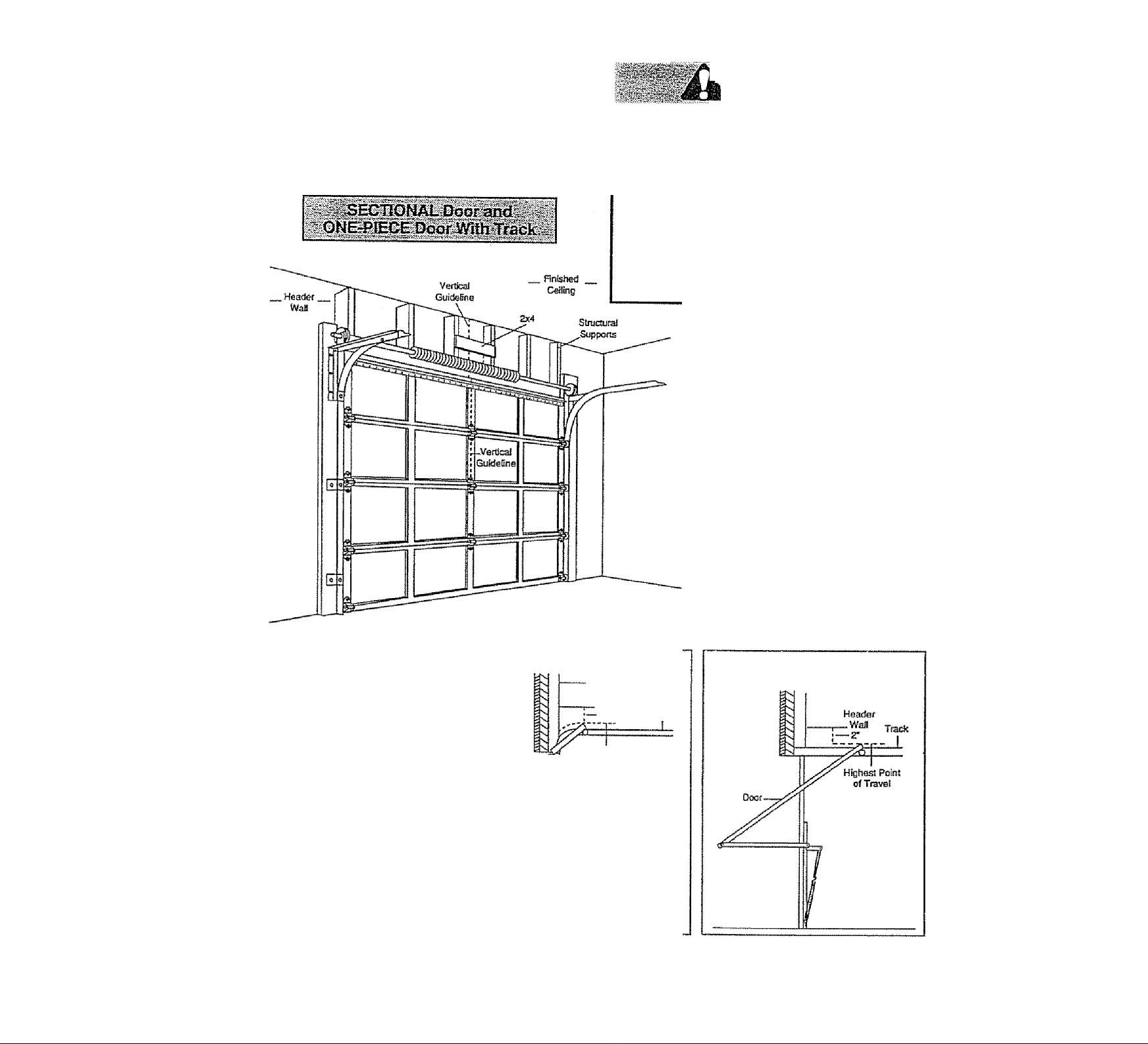
Installation Step 1
Determine HeBder Bracket LocBtion
Installation procedures vary according to
garage door types. Follow the instructions
which apply to your door.
If the header bracket is not rigidly fastened to
a structural support on the header wall or
ceiling, the safety reverse system may not
work properly (see page 30). The door might
not reverse when required, end could cause
serious injury or death.
The garage door springs, cables, pulleys,
brackets and their hardware are under extreme
tension. Do not attempt to loosen, move or
adjust them yourself. Serious personal Injury
or death could result. Cal! for professional
garage door service.
* Close the door and mark the inside
vertical centerline of the garage door.
• Extend the line onto the header wail
above the door.
Remember, you can fasten the
header bracket within 2 feet of the
left or right of the door center only if
a torsion spring or center bearing
plate is in the way; or you can attach
it to the ceiling (refer to page 14)
when clearance is minimal- (It may
be mounted on the wall upside down
If necessary, to gain approximately
1/2".)
If you need to install the header bracket
on a 2x4 (an wall or ceiling), use lag
screws (not supplied) to securely fasten
•the 2x4 to structural supports as shown
here and on page 13.
• Open your door to the highest
point of travel as shown. Draw
an intersecting horizontal line
on the header wall 2" above
the high point This height will
provide travel clearance for the
top edge of the door.
Door clearance brackets are
available for sectional doors
when headroom clearance is
less than 2* *. See accessory
page 38.
Proceed to Step 2, page 14.
Door ■
Ceffing
Header
-Wall
-2* Track
Higliesi Pdnt
of Travel
Sectional door
with curved track
12
One-piece door
with horizontal track
Page 13

Read the Safety instructions on page 12. They also apply to doors without tracks.
' Close the door and mark the
inside verticaJ centeriine of
your garage door. Extend the
line onto the header wall
above door.
if headroom clearance Is
minimal, you can install the
header bracket on the ceiling.
See page 14.
► ¡fyou need to instail the
header bracket on a 2x4 (on
wall or ceiling). use lag screws
(not supp/Ied) to securely
fasten the 2x4 to structural
supports as shown.
One-piece door without track
jamb hardware
• Open your door to the highest point of travel as
shown. Measure the distance from the top of the
door to the floor. Subtract the actual height of the
door. Add 8* to the remainder. (See Example).
* Close the door and draw an Intersecting horizontai
line on the header wall at the determined height.
If the total number of inches exceeds the height
availabie in your garage, use the maximum
height possible, or refer to page 14 for ceiling
instailation.
Proceed to Step 2, page 14.
pivot hardware
EXAMPLE
Distance from top of door
(at highest point of travel) to floor........
Actual height of door
Remainder.,,..,..,,,,,.,....,.,,.,,,............,..,,
Add
....................................................................... ..-r-8"
Bracket height on header wail...,.............„„.,„=12“
(Measure UP from top of CLOSED door.)
....................................—..■.....-SB"
...............
13
...
....................
,.„,......,4"
92"
Page 14

Installation Step 2
Install the Header Bracket
You can attach the header bracket either to the
wall above the garage door, or to the ceiling.
Follow the Instructions which will work best for
your particuiar requirements.
Fasten the Header Bracket to the Wall
' Center the bracket on the vertical guideline with
the bottom edge of the bracket on the horizontal
line as shown (with the arrow pointing toward the
ceiling).
2X4
Slrucsural
ЗиррюЯ
'1
Highest
Point of Travel
(of Garage Door]
Verttcai
Center
Line
' Mark either set of bracket holes (do not use the
holes designated for ceiling mount). Drill 3/16’ pilot
holes and fasten the bracket securely to a structural
support with the hardware provided.
Lag Screws
Sn6*xax1-5/8*
onfy. You must use ¿g scraws to
The nai! hole is for posHionirtg
mount the header btaelteL
Hardware Shown Actual Size
LagSaew
S/IS'-BXI-SB*
Optionai
Wsif Moontiog
Holes
Wai!
Mooniing Holes
[i>
Fasten the Header Bracket to the Ceiling
’ Extend the vertical guideline onto the ceiling as
shown.
’ Center the bracket on the vertical mark, no more
than 6“ from the wail. Make sure the arrow is
pointing toward the wall. The bracket can be
mounted flush against the ceiling when clearance
is minimal
' Mark holes designated for ceiling mount only. Drill
3/16" pilot holes and fasten bracket securely to a
structural support with the hardware provided
CeiSng Mounting Holes
The nail hole is for positioning only
You musl use lag screws So mouns
She header bractes.
Rnishetl
Coiilng
Lag Screws
s/i6’xsxi'Sra'
Header
■ Wall "
1
Page 15

Installation Step 3
Attach the T-rail to the Header Bracket
Hsacfer Wal
• Position the opener on the garage floor below the
header bracket Use packing materiaJ as a
protective base.
If the door spring is in the way you'll need help.
Have someone hold the opener securely on a
temporary support to allow the T-rall to dear the
spring.
• Posrtion the cable pulley bracket against the header
bracket
• Align the bracket holes and ¡oin with a clevis pin as
shown.
• Insert a ring fastener to secure.
Hardware Shown Actual Size
Clevis Pin
S/56‘x2-3/4-
IS
O
o
Ring Fassener
Page 16

Installation Step 4
Position the Opener
Follow Instructions which apply to your door
type as illustrated.
A 2x4 laid flat Is convenient for setting an ideal
door-to-T-rail distance.
• Raise the opener onto a stepladder.
You will need help at this paint if the ¡adder is
not tail enough.
♦ Open the door all the way and place a 2x4 laid flat
on the top section beneath the T-rail.
if the top panel hits the traiiey when you raise
the door, puH dawn on the trolley release arm to
disconnect the inner and outer sections. The
trolley can remain disconnected until Step 12 is
completed.
To prevent damage to steel, aluminum,
fiberglass or glass panel doors, do not rest the
opener on №e door without using a 2x4.
laid Flat
Tmiley
ONE-PIECE Door without Trnck
• With the door fuily open and parallel to the floor,
measure the distance from the floor to the top of
the door.
• Using a stepladder as a support, raise the opener
to the same distance as the door from the floor (it
wifi be at a slight angle as shown).
• The top of the door should be level with the top of
the opener. Do not position the opener more than
2" above this point
Top of Opener
16
Page 17

Installation Step 5
Häng the Opener
Two representative installations are shown.
Yours may be different Hanging brackets shouid
be angled, Rgure 1, to provide rigid support On
finished ceilings, Rgure 2, attach a sturdy metal
bracket to structural supports before installing the
opener. The bracket and fastening hardware are not
supplied. See accessory page 38.
• Measure the distance from each side of the opener
to the structural support
• Cut both pieces of the hanging bracket to required
lengths.
• Drill 3/16' pilot holes in the structurai supports.
• Attach one end of each bracket to a support with
5/16'-18x1*7/8' iag screws.
• Fasten the opener to the hanging brackets with
5/16“-18x7/8“ screws, lock washers and nuts.
• Check to make sure the T*rail is centered over the
door (or in line with the header bracket if the
bracket is not centered above the door).
• Remove the 2x4. Operate the door manually. If the
door hits the rail, raise the header bracket.
The opener coutd fait and Injure someone If ft
is not properly secured. Fasten the opener
securely to structural supports of the garage.
Figure 1
Moäsuro
Dismnca
S/16'-iax7/B’ Scfflw,
5/16" Look Washar
S/16M8 Niit
Figure 2
Stiuctoral
Suppofts
Grease the top and underside of the
rail surface where the trolley
slides. A tube of grease is
supplied.
Hardware Shown Actual Size
Lag Screw
5/ie*-t8x1.7/8*
PI)
Hex Screw
S/16*-16x7/8* NUI5/16--18
Lock Washer 5/16*
Bracket
(Nat SuppiteP) .
S/t 6*-18x7/8* Screw
S/16* Lode Washer
5/16*.18 Nut
HWden
Support
Rrished Ceiling-
:■ (Not Supplied)
S/ie*-18x7/8* Screw
5f16" Lock Wa^r
Page 18

Installation Step 6
Instai! the Premium Control Console
Locate the door control within sight of the door
at a minimum height of 5 feet where small
children cannot reach, and away from all moving
parts of the door and door hardware.
The door control is typically attached directly to the
wall If installing into drywall, drill 5/32" holes and
use the anchors provided. For pre-wired insiaJiaiions
(as In new home œnstrucîian), Console models
may be mounted to a standard single gang box
(Figure 2).
1 .Strip 1/4‘ of insulation from one end of the bell
wire and connect it to the two screw terminals on
the back of the door control: white to 2, and
white/red to 1.
2, Pry off cover along one side with a screwdriver
blade (see Figure 1). Fasten with 6ABx1-1/4‘ self
tapping screws (standard installation) or 6-32x1*
machine screws (pre-wired instaliation) as follows:
• Install bottom screw, allowing 1/8* to protrede
above wall surface.
• Position bottom of door control on screw head and
slide down to secure. Adjust screw for snug fit.
• Drill and install top screw with care to avoid
cracking plastic housing. Do not overtighten.
• Insert top tabs and snap on cover.
3. (For standard installation) Run ttie bell wire up the
Do not connect to live electncal wiring. Connect
only to 24 Volt low voltage wires. Connection to
live wires or higher voltage may cause serious
injury from shock, bum or electrocution.
Children operating or piaying with a garage
door opener can Injure themselves or others.
The garage door could close and cause
serious injury or death.
instail the door control (or any additional push
buttons) out of the reach of children and away
from all moving parts of the door and door
hardware, but H*ere the garage door is visible.
Do riot allow children to operate the push
button(s) or the remote control(s).
A moving garage door could.injure someone
under it Activate the opener only when the
door is properly adjusted, you can see it
clearly, and there are no obstructions to door
travel.
Hardware Shown Actual Size
NMjilriiHIijiHIIïïro
SA0 X1-1M* Screw
CofTtroi Cansofe (std instailalk«)
nm
^ 6-32 xT Screw
Contttsl Console (pre-wired)
11
OiyWaltAnetiore
insuiatect
Stapies
18
Page 19

6. Attach tie User Safety Instruction iabei to the wall
near the door control, and the Maintenance
Instruction label in a prominent location on the
inside of the garage door.
Page 32 explains how to use the door controL
Instsllstton Stsp 7
Instail the Lights and the Lenses
• Instali a 75 watt maximum light bulb in each
socket. The lights wtl! turn ON and remain lit for
approximately 4-1/2 minutes when power is
connected. Then the lights will hjm OFF.
• If the bulbs bum out prematurely due to vibration,
replace them with standard neck 'Garage Door
Opener* * bulbs.
Do NOT connect the power and operate the
opener at this time. The trolley will travel to the
full open position but will not return to the
close position until the sensor beam Is
connected and properly aligned.
See Safety Reversing Sensor Instructions
beginning on page 21.
75 Wa« Ma*.
Guida
Install the lenses:
• Apply slight pressure on the sides of each lens
and slide the tabs into the slots in the side panels.
• For convenience, the lenses may be installed
after Adjustment Step 4 on page 30.
• Reverse the procedure to remove the lenses.
Instailation Step 8
Attach the Emergency
Release Repe and Randie
• Thread one end of the rope through the hole in
the top of the red handle so "NOTICE" reads right
side up as shown. Secure with an overhand knot.
The knot should be at least 1" from the end of
the rope to prevent slipping.
• Thread the other end of the rope through the hole
in the release arm of the outer troiley.
• Adjust rope length so the handle Is 6 feet above
the floor. Secure with an overhand knot.
If it is necessary to cut the rope, heat seal the
cut end with a match or lighter to prevent
unraveling.
Lens
Tab
Lens'
Tab
Do not use the red handle to pull the door
open or closed. The rope knot could become
untied and you could fall. Use the emergency
release only to disengage the troHey and, if
passible, only when the door is closed.
Garage doors are heavy. If the door is open
when the handle is puiied, the door could
close inadvertently if it is not properly
balanced. Serious injury may result to persons
under the door. Make sure the doorway is clear
of persons and obstructions before pulling
handle when door is open.
Overiiarxi
Kjio!
19
Trolley
Ovettiand
Knot
Trolley
Release Arm
Emergency
flelease Handle
Page 20

Instaiiation Step 9
Electrical Requirements
Tq reduce the risk of electric shock, your garage
door opener has a grounding type plug with a third
grounding pin. This plug will on/y fit into a grounding
type outlet,
if the plug doesn't fit into the outlet you have,
contact a qualified electrician to instaii the proper
outlet.
To avoid instaiiation difftcuities,
do not run the opener at this time.
To prevent electrocution or fire, Installation
and wiring must be in compliance with local
electrical and building codes.
Do NOT use an extension cord, 2-w!re adapter
or change the plug in any way to make It fit
your outlet.
Right
Wrong
if permanent wiring is required by your local code, refer to the following procedure:
To prevent electrocution, remove power from
the garage door opener and from the circuit
you plan to use for the permanent connection.
Permanent
To make a permanent connection through the
T/8" diameter hole in the top of the opener
(according to local code):
Remove the opener cover screws and set the
cover aside.
Remove the attached 3-prong cord.
Connect the black (fine) wire to the screw on the
brass terminal; the white (neutral) wire to the
screw on the silver terminal; and the ground wire
to the green ground screw. The opener must be
grounded.
Reinstall the cover.
Connections
Wiring
To avoid insta nation difficulties,
do not run the opener at this time.
Biade
WIra
20
Page 21

The Safety Reversing system
Information you'll need before you begin the Installation of the safety reversing sensor.
The safety reversing sensor must be connected
and aligned correctly before the garage door
opener will move in the down direction. This is a
required safety device and cannot be disabled.
Imiallathn procedures are the same for sectiana!
and one-piece doors.
Without a properly working safety reversing
sensor, persons (particularly children) could
be injured or killed by a closing garage door.
Read and follow all Instructions.
To protect small children, Install the safety
reversing sensor so that the beam will be no
higher than 4“*6'‘ above the garage floor.
Disconnect power to the garage door opener
before Installing the safety reversing sensor.
Be sure power to the opener is disconnected.
The sending eye transmits an invisible light beam to
the receiving eye* The units can be instaJled on
either side of the garage door as long as the sun
never shines directly into the receiving eye lens.
Look at the label on the connector end of each case
to identify the sensors.
The brackets must be connected and fastened so
that the sending and receMng eyes face each other
as shown in Rgure 1.
If an obstruction breaks the light beam while the
garage door is closing, the door will stop and
reverse to full open position and the opener lights
will flash for 5 seconds.
The brackets must be securely fastened to a solid
surface such as the studs on either side of the door,
or add a piece of wood at each location if installing in
masonry construction.
The invisible light beam path must be unobstructed*
No part of the garage door (or door tracks, springs,
hinges, rollers or other hardware) can interrupt the
beam while the door is closing. If it does, use a piece
of wood to build out each sensor mounting locaton to
the minimum depth required for light beam clearance.
Figure 1: Facing the door from inside the garage
21
Page 22

installation Step 10
Instai! the Safety Reversing Sensor
Rgures 2 and 3 show assembly of brackets and
'C* wrap based on the recommended installation of
the sensors as shown on page 21.
However, Figures 4 and S are variations which may
fit your insiallaiion requirements better. Make sure
the wraps and brackets are aligned so the
sensors will face each other across the garage
door.
• Fasten the “C* wraps to the mounting brackets
having square holes, using the hardware shown
in Rgure 2.
• Connect each assembly to a slotted bracket, using
the hardware shown in Rgure 3.
Note the alignment of the brackets for left and
right sides of the door.
• Roger tighten the lock nuts,
• Use bracket mounting holes as a template to
locate and dril! (2) 3/16" diameter pitot holes on
both sides of the garage door, 4‘-6” above the
floor but not exceeding 6*. (See warning on
page 21.)
• Attach bracket assemblies with 1/4*x1-1/2* lag
screws as shown in Rgure 3.
• Adjust right and left side bracket assemblies to the
same distance out from the mounting surface.
Make sure all door hardware obstructions are
cleared. Tighten the nuts securely,
Figure 2
UKkNuts
Figure 3
-Ci:o3s —
War
#10-32
a.
Mounting B tacket
With Square Hotos
1/4X1-1Ä*
Lag Screws
MounSrtg Bracket
with Slot
Mouneig Staoket
with Square Hates
G'Wrafj
#10-32x3/6*
Screws
1/4-20x1/2* CaiTíago Boits
{wHh square shoulder)
mwrap
#10-32x3/8*
Screw
Figure 4
#10x32
Lock Nut
Alternate Wall Mount
Mounting Bracket
With Slot
Hardware Shown Actual Size
11
__
Mtxtnling Bracket
1
Square Hotos
C* Wrap
Sensor
with wire
tndicatar Light
I I III
1^
IMxl-1/2*
Lag Screw
D
Figure 5
1/4'-20x1/2*
Caiiiaga Bafts
Alternate Floor Mount
Sensor with wire
InsScatar Ught
Mourning Bracket
wlh Square Holes
MounSfrsg Bracket
vwth Slot
concrete anchors
(not provided)
1/4'-20
Lock Nut
Attach witti
22
Page 23

» Center each sensor unit in a 'C* wrap with tenses
pointing toward each other across the door (see
Hgure 6).
• Secure sensors with the hardware shown. Roger
tighten the wing nut on the receiving eye to aliow
for final adjustment. Securely tighten the sending
eye wing nut
• Run the wires from both sensors to the opener.
Use insulated staples to secure wire to waJ! and
ceiling,
«Strip 1/4“ of insulation from each set of wires.
Separate white and whiie/black wires sufficiently to
connect to the opener terminal screws: white to 2
and white/black to 3.
Aligning the Safety Sensors
• Plug in the opener. Green indicator lights in both
the sending and receiving eyes will glow steadily il
wiring connections and alignment are correct
The sending eye indicator light will giow regardless
of alignment or obstruction. If the indicator light is
off, dim, or flickering in the receiving eye (and the
invisible light beam path is not obstructed),
alignment is required.
• Loosen the sending eye wing nut and readjust,
aiming directly at the receiving eye. Lock in place.
• Loosen the receiving eye wing nut and adjust
sensor vertically and/or horizontally untii it receives
the sender^s beam. When the green indicator light
glows steadily, tighten the wing nut.
Rgure 6
¡mficator
Ugh!
1/4-23x1-1/2*
Hex Boil
'C'Wrap
Trouble Shooting
1. if the sending eye indicator light does not glow
steadily after installation, check for
• Bectric power to the opener.
• A short in the white or white/black wires. These
can occur under staples or at screw terminal
connections.
• Incorrect wiring between sensors and opener,
• An open wire (wire break).
2. if the sending eye indicator light glows steadily but
the receiving eye indicator light doesn*t
■ Check alignment.
• Check for an open wire to the receiving eye,
3. If the receiving eye indicator light is dim, realign
either sensor.
NOTE: When the invisible beam path is obstructed or
misaligned while the door is closing, the door wilt
reverse. If the door is already open, it will not dose.
The opener fights will flash 10 times. (Ifbutbs are not
instalied, 10 dicks are audible.) See page 21.
Hardware Shown Actual Size
l/4-20xM/a* _
He* Soft
Sonspr
InvistbS« Light Beam
Protection Afea
Sensor
23
Page 24

Installation Step 11
Fasten Door Bracket
I lUINIi
Foilow Instructions which apply to your door
type as illustrated below or on page 25.
A horizontal brace should be long enough to be secured to 2 vertical supports. A vertical brace should
cover the height of the top panel.
The Illustration shows one piece of angle iron as the horizontal brace. For the vertical brace, 2 pieces of
angle iron are used to create a "IF-shaped support The best solution Is to check with your garage door
manufacturer for an opener instailatlon door reinforcement kit
To prevent damage to steel, aluminum,
fiberglass or glass pane! doors, always
reinforce the inside of the door both vertically
and horizontally with an angle iron.
Figure 1
* Center the door bracket on the previousiy marked
vertical guideline used for the header bracket
installation, Nate correct UP placement, as
stamped inside the bracket
* Position the bracket on the face of the door within
the following limits:
A) The top edge of the bracket 2“-4" below the top
edge of the door.
8) The top edge of the bracket directly below any
structural support across the top of the door.
* Mark and drill 5/16" left and right fastening holes.
Secure the bracket as shown in Rgure 1 if there is
vertical reinforcement.
If your installation doesn’t require verticai reinforce
ment but does need top and bottom fastening holes
for the door bracket, fasten as shown in Figure 2
Figure 2
Hardware Shown Actual Size
Nut 5/16-1 a Lode Washei S/16"
Camags Bel!
S/!6".l8x2-t/2‘
24
Page 25

"
............
P!ease read and comply with the warnings and reinforcement instructions on page 24.
They apply to one-piece doors also.
• Center the bracket on the top of the door, in line
with the header bracket as shown. Mark holes.
• Dtiil 5/16" pilot holes and fasten the door bracket
with hardware supplied.
if the door has no exposed framing, drill 3/16* pilot
holes and fasten the bracket with sh6"x1-1/2* lag
screws (not supplied) to the top of the door.
The door bracket may be installed on the top
edge of the door If required for your instailation.
(Refer to the dotted line optional placement
drawing.) Drill 3/16" pilot holes and substitute
5/16"x1-1/2" lag screws (not supplied) to fasten
the bracket to the door.
25
Page 26

Installation Step 12
Connect Door Arm to Trolley
Follow Instructions which apply to your door
type as Illustrated below and on page 27,
Make sure garage door is fully closed. Pull the emergency release handle to disconnect the outer trolley
from the inner trolley. Slide the outer trolley back (away from the door) aboirt 2" as shown In
Rgures 1,2 and 3.
Rgure 1:
• Fasten straight door arm section to outer trolley
with the the 5/16*xr clevis pin. Secure the
connection with a ring fastener.
« Fasten curved door arm to the door bracket in the
same way, using the S/IS'xl-IM" clevis pin.
inner Troilsy
Rgure 2:
• Bring arm sections together. Rnd two pairs of holes
that line up and join sections. Select holes as far
apart as possible to increase door arm rigidity.
Straight
Door Arm
Cle«a Pin
S/16M-1/4'
Cusved
i3oor Arm
igure 1
Hole Alignment Alternative
Figure 3:
• If holes In curved arm are above holes in straiaht
arm, disconnect straight arm. Cut about 6** from
the solid end. Reconnect to trolley with cut end
down as shown.
• Bring arm sections together.
• Rnd two pairs of holes that line up and join with
screws, lock washers and nuts.
Hardware Shown Actual Size
O
Nutsns'-IB Lock Washer S/1 S' Ring Fastener
Door Bracket
Eni0f||ency
Heiease
Handle
Scmws
sne'-iew/s*
Figure 2
Cut This End
o
' CieHs Pin
m e 'xV {Trolley)
Proceed to Adjustment Step 1, page 28, Trolley will re-engage automatically when the opener is operated.
Clevis Pin Hex Screw
o
(Door Bracket) 5/l6‘-iax7/B*
26
Figure 3
Page 27

Assemble the Door Arm:
• fasten the straight and curved door arm sections
together to the longest possible length, with a 2 or 3
hole overlap.
• With the door dosed, connect the straight door arm
section to the door bracket with the 5-16" x 1 -1/4"
clevis pin.
• Secure with a ring fastener.
On one-piece doors, before donnecfing the door arm to the trolley the travel limits must be adjusted. Limit adjust
ment screws are located on the left side panel as shown on page 28. Follow adjustment procedures below.
Door
aitig
Ad}ustment Procedures for One-Piece Doors
open Door Adjustment:
Decrease UP limit
' Turn the UP limit adjustment screw counter-
dockwise 5-1/2 turns,
- Press the Wait Control push bar. The trolley will
travel to the fully open position.
> Manually raise the door to the open position
(parailel to the floor), and lift the door arm to the
trolley. The arm ahouid touch the trolley just in
back of the door aim connector hole. Refer to the
fully open troliey/door arm positions in the
illustration. If the arm does not extend far enough,
adjust the limit further. One full turn equals 2* of
trolley travel.
Connect the door arm to the trolley.
• Close the door and join the curved arm to the connector hole in the trolley with the remaining clevis pin. It may
be necessary to lift the door slightly to make the connection.
• Secure with a ring fastener.
• Run the opener through a complete travel cycle. If the door has a slight “backward" slant in full open position
as shown in the Illustration, decrease the UP limit until the door is parallel to the floor.
'Turn the DOWN limit adjustment screw clockwise
5 complete turns.
‘ Press the Wall Controi push bar. The trolley will
travel to the fully closed position.
> Manually dose the door and lift the door arm to the
trolley. The aim should touch the trolley just ahead
of the door arm connector hole. Refer to the fully
closed trolley/door aim positions in the illustration. If
the arm is behind the connector hole, adjust the limit
further. One full turn equals 2" of trolley travel.
Closed Door Adjustment:
Decrease DOWN limit '
27
Page 28

Adjustment Section: Pages 28 - 30
Adjustment Step 1
Adjust the UP and DOWN Limits
Do not make any limit adjustments until the
safety reversing sensors are completely
installed.
Umit adj'ustment settings reguiate the points at
whidi the door will stop when moving up or down.
The door wiii stop in the up direction if anything
interferes with door travel The door will reverse in
the down direction if anything interferes with the
dooriravei (including binding or unbalanced doors).
To operate the opener, press the Door Ckinirol push
button. Run the opener through a complete travel
cycle.
• Does the door open and close completely?
• Does the door stay closed and not reverse
unintentionally when fully closed?
If your door passes both of these tests, no limit
adjustments are necessary unless the reversing test
fails (See page 30).
Adjustment procedures are outifned below. Riin
the opener through a complete travel cycle after
each adjustment.
Repeated operation of the opener during
adjustment procedures may cause the motor to
overheat and shut off. Simply wait 15 minutes
and try again.
Read the procedures carefully before proceeding to
Adjustment Step 2. Use a screwdriver to make limit
adjustments.
Improper adjustment of the travel limits will
interfere with the proper operation of the
safety reverse system. The door might not
reverse properly when required and could
seriously injure or kill someone under it Test
the safety reverse system following all
adjustments to the travel limits. See page 30.
r—
....—ussa.
Cover y
PtDtedjan
Bdt
iCZCs
CD CD O CD rp
"'ciJ'""'"""'“"
.........
.............. ............................
Left Side Panel °
X /
Limit Adjustm^t
Scrsws
© ^
Adjustaent Label
How and When to Adjust the Limits
• If the door does not open completely, but
opens at least five feet:
Increase up travel Turn the UP limit adjustment
screw clockwise. One turn equals 2* of travel.
NOTE: To prevent the trolley from hitting the
cover protection bait, keep a minimum distance
of 2-4*' between the trolley and the bolt
• If door does not open at least 5 feet:
Adjust the UP (open) force as explained in
Adjustment Step 2,
• If the door does not close completely:
Increase down travel Turn the DOWN limit
adjustment screw counterclockwise. One turn
equals 2“ of travel.
If the door still won't close completely and the trolley
bumps into the pulley bracket (see page 4 or 5), try
lengthening the door arm, (see page 26).
If you have adjusted the door arm to the maximum
length and the door stiil will not dose completely,
lower the header bracket. See Installation Step 1,
pages 12 and 13.
• If the opener reverses in fully closed position:
Decrease down travel. Turn the DOWN limit
adjustment screw clockwise. One turn equals 2" of
travel.
V If the door reverses when closing and there is
no visible interference to travel cycle:
if the opener lights are flashing, the Safety Reversing
Sensors are either not installed, misaligned, or
obstructed. See Troubleshooting, page 23, ,
Test the door for binding; Pull the manual release
handle. Manually open and close the door. If the door
is binding, call for garage door service. If the door is
not binding or unbalanced, adjust the DOWN (dose)
force. See Adjustment Step 2.
28
Page 29

Adjustment Step 2
Adjust the Force
Force adjtjsirnent contrais are located on the right
Side рале1 of the opener. Force adjustment settings
regulate the amount of power required to open and
dose the door.
The door wifi stop in the up direction if anything
interferes with its travel. The door wii! reverse in the
down direction if anything interferes with its travel
(including binding or unbalanced doors).
If the forces are set too light, door travel may be
intemipted by nuisance reversals in the down
direction and stops in the ф direction. Weather
conditions can affect the door movement, so
occasional adjustment may be needed.
The maximum force adjustment range is 260 degrees,
about 3/4 of a complete turn, Oo not force controls
beyond that point. Turn force adjustment controls
with a screwdriver.
Too much force on the door will Interfere with
the proper operation of the safety reverse
system. The door might not reverse properly
when required and could seriously Injure or
kill someone under it Do not increase the
force beyond the minimum amount required
to close the door. Do not use the force
adjustments to compensate for a binding or
sticking garage door. Test the safety reverse
system following all adjustments to force
levels. See page 30.
Forea Adjussment
Contrais,
Acflustmem taba!
How and When to Adjust the Forces
Test the DOWN (close) force
Grasp the door bottom when the door is about
halfway through DOWN (close) travei. The door
should reverse. Reversal halfway through down
travel does not guarantee reversal on a one-inch
obstruction. See page 30. If the door is hard to
hold or doesn’t reverse, decrease the DOWN (close)
force by turning the control counterclockwise.
Make 10 degree turn adjustments until the door
reverses normally. After each adjustment, run the
opener through a complete cycle.
Test the UP (open) force
Grasp the door bottom when the door is about
halfway through UP (open) travel. The door should
stop, if the door is hard to hold or doesn't stop,
decrease UP (open) force by turning the control
counterclockwise.
Right Sida Panel
Make 10 degree turn adjustments unffl the doorstops
easily. After each adjustment, run the opener through
a complete travel cycle.
if the door doesn’t open af least 5 feet
Increase UP (Open) force by turning the control
clockwise. Make 10 degree turn adjustments until
door opens completely. Re-adjust the UP limit if
necessary. After each adjustment, run the opener
through a complete travel cycle.
If the door reverses during the down (close) cycle
and the opener lights aren’t flashing
increase DOWN (close) force by turning the control
clockwise. Make 10 degree turn adjustments until the
door completes a close cycie. After each adjustment,
run the opener through a complete travel cycle. Do
not increase the force beyond the minimum
amount required to close the door.
29
Page 30

Adjustment Step 3
T&st The Safety Reversing Sensor
* Press the remote control push button to open the
door.
* Place the opener carton in the path of the door,,
* Press the remote control push button to dose the
door. The door will not move more then an inch,
and the opener lighifs) will flash.
Professional service is required if the opener
doses the door when the safety reversing
sensor is obstructed.,
The garage door opener will not close from a
remote control If the Indicator light in either
sensor Is off (alerting you to the fact that the
sensor Is misaligned or obstructed).
The garage door can be dosed by pressing and
holding the Door Control push button until down
travel is completed.
Adjustment Step 4
Test the Safety Reverse System
Without a properly working safety reversing
sensor, persons (joarticu/arfy chiidren) could be
seriously injured or killed if trapped by a closing
garage door. Repeat this test once a month.
N
I
a
Safety RevBEStng Sensor
Safely Revarsirig Sensor
Test:
«Place a one-inch board {or a 2x4 laid fiat) on the
floor, centered under the garage door.
• Operate the door in the down direction. The door
must reverse on striking the obstruction.
Adjustment;
If the door stops on the obstruction, it is not traveling
far enough in the down direction.
• Increase the DOWN limit by turning the DOWN
limit adjustment screw counierciockwise 1/4 turn.
• Repeat the test.
On a sectional door, make sure limit
adjustments do not force the door arm beyond a
straight up and down position. See the
illustration on page 26.
• When the door revetses on the one-inch board,
remove the obstruction and am the opener through
3 or 4 complete travel cycles to test adjustment.
If the door will not reverse after repeated
adjustment attempts, call for professional
garage door service.
Failure to test and adjust the safety reverse
sysfem may result in serious injury or death to
persons trapped by a closing garage door.
Repeat this test once a month and adjust as
needed.
6ARAGE DOOR
Onwodi SoanJ
■ (or a 2x4 iaid na!)
Important safety check
Repeat Adjustment Steps 1, 2 and 4 after:
• Each adjustment of door ami length, force controls
or limit controls.
• Any repair to or adjustment of the garage door
(including springs and hardware),
• Any repair to or buckling of the garage floor.
• Any repair to or adjustment of the opener.
30
Page 31

IMPORTANT SAFETY INSTRUCTIONS
To reduce the risk of severe injury or death to persons:
1. READ AND FOLLOW ALL INSTRUCTIONS,
2. Do not permit children either to operate or to
play with the opener. Keep remote control in a
location inaccessible to children.
3. Operate opener only when the door is in full
view and free from any obstnictlon. Keep the
door in sight until it is completely closed. NO
ONE SHOULD CROSS THE PATH OF THE
MUViNQ DOORm
4. Check safety reversal system monthly. See
page 30. The garage door Afí/STreverse on
contact with a one-inch {or a 2x4 board laid
flat) object placed on the floor. If an adjustment
is made to either the force or the Hml of travel,
both adjustments may be needed and the
safety reversal system must be checked.
Failure to properly adjust the opener may
result in severe injury or death.
Care of Your Opener
Limit and force adjustment controls
Limit Controls Force Controls
Adfustment Label
{Locased on the leli side panel)
Weather conditions may cause some minor
changes in door operation requiring some re
adjustments, particularly during the first year of
operation.
Pages 28 and 29 refer to the limit and force
adjustments. Only a screwdriver is required. Follow
the instructions carefully.
Repeat the safety reverse test (page 30) after any
adjustment of limits or force.
Ai^usiment labe)
(Localed on the right side panei)
'é'
6. if possible, use the emergency release only
when the door is in a closed position. Caution
should be taken whenever the disconnect cord
is actuated with the door open. Weak or broken
spnngs may cause the door to fail rapidly,
causing injury or death to persons.
6. KEEP GARAGE DOORS PROPERLY
BALANCED. See page 3. An improperly
balanced door may not reverse when required
and could result In severe injury or death.
Repairs to cables, spring assemblies and other
hardware must he made by a professional
garage door person.
7. Disconnect the electric power to the garage
door opener before maidng any repairs or
removing the covers.
8. SAVE THESE INSTRUCTIONS.
The remote control
The lithium batteries should
produce power for up to
5 years. To replace batteries,
use the visor clip or screwdriver
blade to pry open tfie case as
shown, {“Open" location is
stamped on back of remote
contro! case.) insert batteries positive side down.
Replace cover as follows. S-Function remote: Insert
the 3 tabs at the opposite end and snap shut
3-rUNCnON
Oped tftfa end
Jiistto
aacJctng
housing
COMPACT
Twist hem,
xo open
Compact 3-Function remote: Snap shut along both
sides.
Dispose of old batteries properly.
Keep batteries away from small children. If
swallowed, promptly notify doctor.
Maintenance Schedule
Once 3 Month
Manually operate door. If it is unbalanced or
binding, caí! for professional garage door service.
Check to be sure door opens and closes fuHy.
Adjust limits and/or force if necessary.
{See pages 28 and 29.)
Repeat the safety reverse test Make any
necessary adjustments (See page 30).
Twice a Year
Check chain tension. Disconnect trolley first
Adjust if necessary (See page 11),
Once a Year
Oil door rollers, bearinqs and hinoes. The opener
does not require additional lubrication. Do not
grease the door tracks.
31
Page 32

Operation of Your Opener
Activate the opener with any of the following:
• The Remote Control; Hold push button down until
the door starts to move,
" The Door Control; Hold push button down until
the door starts fn move
w V-l WWI O LCiAi um? i-W t f c\^ w VC 4«
« The Outdoor Key Switch or Keyless Entry: (See
Accessories)
When the opener is activated with the safety
reversing sensor installed and correctly aligned:
1. If open, the door will close. If closed, the door will
open,
2. If closing, the door will reverse.
3. If opening; the door will stop (allowing space for
entry and exit of pets and for fresh air).
4- If the door has been stopped in a partially open
position, it will close.
5. If obstaicted while closing, the doorwii! reveree.
6. If obstructed while opening, the doorwiit stop.
7. The garage door will reverse Irr the closing cycle
when the invisible beam is broken. If fully open,
the door will not close when the beam is broken.
"TTiD CDnCAf* hiSC nA rSuffOAf tn AAOAlAA
111^ is-c#I i-oim«I I Itd.w i 11«# iL sI I IJ 1x5 xJLa/lu«I ill ix^ w$x5•
If the sensor is not Installed, or is not aligned
rniTArtiv fhA dnnf rln<5A finrn pnv rpinnti^
luw t i wx<xi Y i w 1x7 SJ \JxJi wYXJi t i 11 wl 1 c OJ IV I x#l 1
transmitter. You can close the door with the Door
Control, the Outdoor Key Switch, or Keyless Entry,
however, if you activate them until down travel Is
complete. If you release them too soon, the door will
f/a t/yi j"gy <3
# *
The opener lights will blink for S seconds when the
safety reversing sensor causes the door to reverse.
The Opener Lights wii! turn on under the following
conditions: When the opener is initially plugged in;
when the power is inteirupted; when the opener is
activated. They will turn off automatically after 4"1/2
minutes or provide constant light when the Light
feature on the Premium Control Console is activated.
SECURITY+ models: Lights will also turn on when
someone walks through the open garage door. Bulb
size is 75 watts maximum.
Weak or broken springs could allow an open
door to fall (either rapidly or unexpectedly)t
resulting in serious in}ury, death or property
damage. If possible, use the emergency
release rope and handle only when the door is
fully closed.
To open the door
manually:
Release Arm
Tfoiley
The door should be
fully closed If possible.
Pull down on the red
emergency release
handle and lift the door
manually. To
Einefigency
Release Handle
<Pun Down)
Manual disconnect
fpnnnnpcf thA rfnnr tn
the opener, press the
Door Control push
button.
position
The lockout feature
prevents the trolley from
reconnecting automatically., ¡ ^
Pull the emergency handle
Release Airn
down and back (toward the
opener). The door can then
be raised and lowered
manually as often as
FtAAoeciiaA/ Та Hícíaaaíüaíi
níívAÍoocli у» *w и1хэЦ1 iUcÍUt5
the Lockout Feature, pull
the emergency handle
straight down. The trolley
Emergency
Balease Haridfe
(PüÜ Dovm & Back
Towards Opener)
will reconnect on the next Lockout position
UP or Down operation.
Operation of trie Door
(SECURiTY’i* models: See additional
Press the lighted push button to open or close the
door.
Press again to reverse the door during the dosing
cycle or to stop the door while ifs opening.
Premium Console:
L/ghfFeatore- Press the large round Light button,
the opener lights are off, they will turn on. If the
opener lights are on, (even in the 4*1/2 minute
automatic cycle) they will turn off.
But if you use the Light button to turn the lights on
and then activate the opener, the lights will turn off
after 4-1/2 minutes,
The Light button will not control the opener lights
when the door is in motion.
Controls (see page 18)
programming features, next page,)
Premium Console (cont):
Lock Feature - The Lock feature is designed to
prevent operation of the door from remote controls.
However, the door will open and close from the Door
Control, the Outdoor Key Switch and the Keyless Entry
Accessories,
If
To Activate; Press and held the small round Lock
button for 2 seconds. The push button light will flash
as long as the Lock feature is on.
To turn off: Press and hold the Lock button again
for 2 seconds.The push button light will stop
flashing. The Lock feature wii! also turn off whenever
the "SRT" button on the opener pane! is activated.
32
Page 33

Receiver and Remote Control Programming
SE€URnT+
Your garage door opener receiver and remote control
have been pre-set at the factory. The door will open
when you press the LARGE remote control push
button. The code between the remote control and the
receiver changes with each use, randomly accessing
over 100 billion new oades.
The 3-function remote control can also activate
additional SECURITY*®» garage door openers and/or
light controls.
Your SECURrTY-f opener will operate with:
• several SECURITY*® remote controls (with blue
push buttons) utilizing up to 8 functions.
• one SECURITY*® Keyless Entry System (Mode!
139.53684).
Follow the instructions beiow to program your opener
to match any additional remotes you may purchase.
See Accessories on page 38.
To comfW with FCC nites, ac^usttnent or m«£iicau'ahs of this recoiver
andior JransmitSef ara po5ii33fted, except for diangasg trio ccda seUitKi «
replacing tha taSety, THEHE ABE NO OmSB USER SERVICEABLE
PARTS.
Children operating or playing with a garage
door opener can injure tftemseives or others.
The garage door could dose and cause serious
Injury or death. Do not allow children to operate
the door push button(s) or remote control's).
A moving garage door could Injure or kill
someone under It Activate the opener only
when you can see the door clearly, it is free of
obstructions, and Is properly adjusted.
Figure 1
Seteci a remoia ссп&Ы posh
btittan w operate openar
To Add A Remote Control
If you have a Premium Control Console:
1. With the door closed, press and hold a remote
Gontroi push button. See Rgure 1.
2. Press and hold the Light button on the door
control.
3. Press and hold the door control push button.
4. After the opener light flashes, release all buttons.
Test by pressing the remote push button.
If you do not have a Premium Control Console:
1. Press and /ю/d the selected remote control push
button. See Rgure 1.
2. Then press and release the SRT (leam) button on
the back panel of the opener, Rgure 2„ The
indicator light on ttie panel will begin to blink and
the opener light will ffash once.
3. Release the remote push button.
Test by pressing the remote push button.
To Erase All Remote Control Codes
Press and hold the SRT button on the opener panel
until the indicator light turns off (about 6 seconds). All
remote control codes are now erased. Then follow
the steps above to re-program each remote control.
SECURlTY-i"
3-Function
Remote Control
To Control the Opener Light (Premium Consoles)
With SECURfTY-® remote controls, a push button can
be programmed to operate the opener light without
opening tie door.
1. With the door dosed, press and bold the remote
button that you want to control the light.
2. Press and hold the Light button on the door
control.
3. Press and hold the Lock button on the door control.
4. After the opener light flashes, release ail buttons.
Test by pressing the remote push button. The opener
light should turn on or off but the door should not move.
SECURITY*®
Garage Door Opener
Figure 2
33
Page 34

Having a Problem?
Situation
The opener doesn't
operate from either
the Door Control or
the remote control:
Opener apemtes
from the remote
control, but not from
the Door Control: -
The door operates
horn the Door
Control, but not ft'om
the remote control:
Probable Cause and Solution
1. Does the opener have electric power? Plug a lamp into the outlet. If it doesn't light,
check the fuse box or the dncuit breaker. (Some outlets are controlled by a door switch,)
2. Have you disabled all door locks? Review installation instruction warnings on Page 11,
3. Is there a buHd-up of ice or snow under the door? The door may be frozen to the
ground. Remove any restriction,
4. The garage door spring may be broken. Have it replaced,
5. Repeated operation may have tripped the overload protector in the motor. Wait
IS minutes. Try again.
1. Is the Door Control lit? Jf not, remove the bell wire from the opener terminal screws.
Short the red and white terminals by touching both terminals at the same time with a
piece of wire, if the opener runs, check for a faulty wire connection at the Door
Control, a short under the staples, or a broken wire.
2. Are the wiring connections correct? Review Step 6, page 18.
1. Is any door push button flashing? If your model has the Lock feature, make sure the
lock is Off.
2. Your opener needs to re-leam a remote control code. Refer to Instructions on the
AfliSnOi* nonol
wijtSi ttSi Ucu itSK
3. Program the receiver to match the remote control code,
4. Repeat the receiver programming procedure with ail remote controls.
The remote control
has short range:
Opener noise is
disturbing in living
quarters of home:
The garage door
opens and closes
by itself:
The door doesn't
open completely:
1. Change the location of the remote control in your car.
2. Check to be sure the antenna on the side or back pane! of opener extends fully
downward.
3. Some installations may have shorter range due to a metal door, foil backed
insulation, or metal garage siding. (Antenna Extender Kit 41A3504)
If operational noise is a problem because of proximity of the opener to the living
quarters, the Vibration Isolator Kit 41A3263 can be installed. This kit was designed to
minimize vibration to the house and is easy to install.
1. Be sure that all remote control push buttons are off.
2. Remove the bel! wire from the Door Control terminals and operate from the remote
control only, if this solves the problem, the Door Control is faulty (replace), or there is
an intermittent short on the wire between the Door Control and the opener,
3. Clear memory and reprogram ail remote controls.
1. is something obstructing the door? Remove the obstruction or repair the door.
2. if the door has been working property but now doesn't open all the way, increase the
up force. See page 29.
3. If door opens at least 5 feet, the travel limits may need to be increased. One turn
equals 2 inches of travel. See page 28.
Repeat the safety reverse test añer the adjustment is complete.
The door stops but
doesn't close
completely:
Review the travel limits adjustment procedures on page 28.
Repeat the safety reverse test añer any adjustment of door arm length, close
force or down limit.
34
Page 35

Having a Problem? (continued)
Situation
The door opens but
woni dose:
The door reverses for
no ^parent r^son
srtd opener liphts
don't blink:
The door reverses for
no apparent reason
and opener lights
blink for S seconds
Ci» Xi eSr 1 W fcr J ¿y f t ■
Probable Cause & Solution
1. if the opener lights blink, check the safety reversing sensor. See page 23.
2. If the opener lights do not biink and it is a new installation, check the down force.
See Adjustment Step 2, page 29, For an existing installation, see below.
Repeat the safety reverse test añer the adjustment is complete.
1. Is something obstructing the door? Pull the red emergency release handle. Operate
the door manually. If it is unbalanced or binding, cal! for professional garage door
service.
2. Clear any ice or snow from the garage floor area where the door closes.
3. Review the force adjustment procedures on page 29.
4. If door reverses in the fully c/osedposition, decrease the travel limits (page 28).
Repeat safety reverse test after adjustments to force or travel limits. The need
for occasional adjustment of the force and limit settings is normal. Weather
conditions in particular can affect door travel
Check the safety reversing sensor. Remove any obstruction or align the receiving eye.
See page 23.
The opener lights:
The opener strains or
maximum forcé is
needed to operate
door:
The opener motor
hums briefly, then
won't work:
The opener won’t
operate due to
power failure:
.., don’t turn on;
Replace the fight bulbs (75 watts maximum). Use a standard neck garage door opener
buib if regular bulb bums out.
... don’t turn off:
is tie Light feature on? Turn it off.
The door may be out of balance or the springs are broken. Close the door and use the
emergency release to disconnect the trolley. Open and dose the door manually, A properly
balanced door will stay in any point of travel while being supported enflrely by Ks springs, if it
does not, disconnect tie opener and call a professional garage door serviceman. Do not
increase the force to operate the opener
1. The garage door springs are broken. See above.
2, if the problem occurs on the first operation of the opener, door may be locked. Disable
the door lock. If the chain was removed and reinstalled, the motor may be out of phase.
Remove the chan; cycle the motor to the down position, Observe the drive sprocket
When !t tjms In a clockwise direcfion and stops in the down position, reinstall the chain.
Repeat the safety reverse test after the adjustment is complete.
1. Use the emergency release to disconnect the trolley. TTie door can be opened and dosed
manually. When the power is restored, press the Door Control push button and trolley will
automatically reconnect (unless trolley is in tockoirt position.) See page 32,
2. The Emergency Key Release accessory (for use on garages with no service door)
disconnects the trolley from outside the garage in case of power failure.
The chain droops
KJI o ti tJf iv #
It is norma! for the chain to droop slightly in the dosed door position. Use the
emergency release to disconnect the troiley. If the chain returns to normal height when
the trolley is disengaged and the door reverses on a one-inch board, no adjustments
are needed (see page 11).
oc
Page 36

Rail Assembly Parts
Repair Parts
Instailatlon Parts
KEY
PART
NO.
NO. DESCRIPTION
41A4884 Pfemium control console
1
2 41A5032
3 10A19
4
288134
6 31D431
6 318430
7
10A2
8
41A2S28
9
41A4353
10
217A238
11
178B35 Curved door anm section
12 41AS04?
13 41A4373A Safety sensor kit (receiving and sending eyes)
14
12B483
IS 12B4B4 Square Hole Bracket
16
12B48S
17
12B3S-0
18 178834
41A3475-4
41A4116
114A2122 Owner's manual
3-functIon remote control housing
(no circuit board)
3V 2016 Uhium battery (2 required)
Visor clip
Keyless entry keypad cover
Keyless entry battery cover
t2Volt battery
Emergency rope iSt handle assembly
Header bracket w/devis pin & fastener
2*c»nduGior bell wire - white & wh'rte/red
Door bracket w/olevis pin & fastener
with 3' 2-condudor bell wire attached
"C" Wrap Bracket
Slotted Bracket
Hanging brackets
Straight door arm section
NOT SHOWN
installation hardware bag (Includes hardware
illustrated on page 7).
Safety sensor hardware
Jjl^^yy
NO.
1
2 41A3489
3 1B3117
4
5 41B2616
6 41A3473 Chain and cable
PART
NO.
1A995
1838110
83A4
41A3534
DESCRIPTION
Master link kit
Compiete trolley assembly
T-rail "Center section
T-rail - end section
Cable pulley bracket assembly
flail grease
NOT SHOWN
flail assembly hardware kit
(Includes hardware illustrated on
page 7).
17
<d~\
18
36
Page 37

)pctner Assembly Parts
Repair Parts
KEY
PART
NO,
NO.
31D380
1
41C4220A
2
41A2817
3
4 41B4245
41C4253
5
41A5021 -2
6
7 41A4351
175B88
8
DESCRIPTION
Sprocket cover
Oear and sprocket assembly
Complete with:
Spring washer
Thrust washer
Retaining ring
Bearing plate
Roli pins (2)
Drive gear and worm gear
Helical gear w/retainer and grease
Drive/worm gear kit w/grease
Roll pins (2)
Line cord
Wire harness assembly w/piug
Receiver logic board assembly
Complete with:
Logic board
End pane! w/aJi labels
End pane! w/ail labels
Light socket
KEY
NO.
9
10
11 12A373
12
13
14
15
16
17
18
19
20
37
PART
NO.
108D4S-2
30B363
41A3150
41D3058
41D0328-7
41D3462
41C4398A
41A2826
41A2822A
41A4352
41A2825
DESCRIPTION
Lens
Capacitor ^ 1/2HP
Capacitor bracket
Terminal block w/screws
Universal replacement motor &
bracket assembly
Complete with: Motor, worm,
bracket, bearing assembly,
RPM sensor
Cover
Helical gear & retainer w/grease
Limit switch assembly
RPM sensor assembly
Shaft bearing kit
Interrupter cup assembly
End panel
NOT SHOWN
Opener assembly hardware kit
{includes screws not designated by
a number in itiusiration).
Page 38

Accessi
Sears offers rr
Sears model ni
139.S3702
139.53703
139.53704
139.53705
lany useful accessories for your garage door opener. They are IHusirated below vi Ith
jmbers and descriptions. '
Emergency Key Release:
Required for a garage with NO
access door. Enables homeowner
to open garage door manually from
outside by disengaging trolley.
Outdoor Key Switch:
Operates the garage door
automalicaily frcHn outside when
remote control is not handy.
8 Foot Rail Extension
To allow »t 8 foot door to c^n fiilly
10 Foot Rail Extension:
lb allow a 10 foot door to open fully
139.53681
139.53680
139.53684
139.
53686
©
1^
SECyRITY'f 3-Function Remot
Control:
Includes visor clip.
SECURITY^ Compact
3*Futiction Remote Control:
With loop for attaching key ring.
(Available April, 1997)
SECURITY-«- Keyless Erriry:
Enables homeowner to operate garage
door opener from outside by entering a
password. Also can add a temporary
password for visitors or service
persons. This temporary password can
be iimfted to a programmable number
of hours or entries.
Plug-In Light Control:
Enables homeowner to turn on a
lamp, television or other appliance
from car, bedside, or anywhere In
the home with a remote.
(Available April, 1997)
Support Brackets:
For finished ceilings or where
additional support is required,
based on garage construction,
includes brackets and fastening
hardware.
We recommend that you program your password
before you Install the Keyless Entry. You will not
need assistance, and you can test the reception at
the mounting location before Installation.
If you have a Premium Control Console:
With the door closed, press the four digit password
desired, then press and hold Enter.
Press and hold the light button on the door contra).
Press and hold the door control push bar-
Afterthe opener light flashes, release all buttons.
To Add the
139.53709
Door Clearance Brackets:
(For Sectional Doors On/yf
Replaces top brackets and rollers on
door to reduce height of door travel.
For use when installing opener in
garage vdth low headroom clearance.
.................................................
Keyless Entry
..........
If you do not have a Premium Control Console:
1. Choose a4-digit password using numbers from
0 to 9 {a number can be used more than once, for
example, 4, 0, 4,1).
2. Press the four buttons for the password, then
press and hold the Enter button. The indicator light
on the door opener panel will blink.
3. Press and release the SRT (team) button on the
opener panel After the opener light flashes,
release the Enter button.
Test by pressing the password, then press Enter. The
door should begin to move.
38
Page 39

Access Doar/Outside Key Retease Accessory.
|nci0X
Chain Tension...™..
.................
.
Electrical Safety Warnings..
Garage Door
Testing for balance, binding and sticking.
Determining high point of travel:
Sectional door.............
One-piece door...........
Disabling existing locks.
Door clearance brackets (for garages with low headroom),
Force controls
Adjustment procedures
Problems that might require force adjustments
Safety warnings.
Door hardware
Maintenance instmction label
Reinforcement requirements.
Removing of all ropes
............... .
Possible door damage.
Travel limits
Adjustment procedures.
Problems that might require limit adjustments.
Safety warnings.........................................................
• V « •
,3, 28, 31
.12
.13
...3, 11
.12, 38
.
......
4, 29
.....
34, 35
.....29, 31
,.3, 9,11,12,18, 31,32
,11,28
,4,24
..3,11
,16, 24
*C.O
..34. 35
OQ 0"i
..do, Ol
Manual (Emergency) Release Rope & Handle
Lockout feature......
Manual disconnect.
Safety warnings.....
T*i2t#Tirti 1*1 «aIo
1 cif lllillciio
Door control connections
.........
Safety reversing sensor connections.
Operational Noise
L I iwIOk« « i.ncLM V« «1 • » n « >j h « If «« w«
Vibration noise (isolator kit)
.........
Receiver and Remote Control
Programming the receiver
Erasing all codes
...........................
........
.
.
Activating other openers....
Safety warning........................................
Problems with remote control operation
Safety Reverse Test Procedure ,.,,,,.,,.,.
Testing required
.........................................
Safety reverse system problems
Securing header bracket to wall
Adjusting travel limits.
..............................
Applying excessive force on the door..
Buckling or uneven floor............
.
......,.,32
11. 19,31,32
....18
.,..23
.,..11
.34
„33
I!«.'-
„33
..33
.
......33
........34
.
..................
.30
,11,30. 34, 35
.
...........
,„..„..12
.
.......
....,„„..28
...................
29
*4' S
Safety Warnings..,
......
..........
..
User Instruction Label for garage wall
,„,2, 3, 9. 11,12, 16,18, 19, 20, 21.24. 28. 29, 30. 31, 32, 33
.
....................................................................................................................................................................... .„.„..„..,....,„,.11, 18
39
Page 40

For professional installation
Call 24 hours a day, 7 days a week
1 -800.865-6500
For the repair or replacement parts you need
Cal! 7 am - 7 pm, 7 days a week
1 -800-366-PART
(1-800-366-7278)
For in-home major brand repair service
Call 24 hours a day, 7 days a week
1-800-4-REPAIR
(1-800-473-7247)
For the location of a Sears Repair Service Center in your area
Call 24 hours a day, 7 days a week
1-800-488-1222
For information on purchasing a Sears Maintenance Agreement
or to inquire about an existing Agreement
Cal! 9 am - 5 pm, Monday-Saturday
1-800-827-6655
The model number label Is located under the light lens on the
front end panel of your opener. When requesting service or
ordering parts, always give the following information:
- Product Type » Part Number
- Model Number - Part Description
America‘s R&pairSpedalists
SEARS WARRANTY
I
For 90 days from the date of purchase, Sears wifi repair this Garage Dcfor Opener, free of charge, if defective in material or
workmanship-
From the 91si day until one year trom the date of purchase, Sears will furnish repiacemenl parts for any defedive parts, free of charge
You pay for tabor,
1/2HP MOTOR; After 1 year and through S years, if the motor on this Garage Door Opener is defective, Sears will furnish a reptacement
motor, free of charge. You pay for labor.
EXPENSE FROM PROPERTY DAMAGE DUE DIRECTLY OR INDIRECTLY FROM THE USE OF THIS PRODUCT. Some states do
not allow the exclusion or limitation of Incidental or consequential damages, so the above limitation or exclusion may not apply to you.
This warranty does not cover light bulbs or repair parts necessary because of operator abuse or negHgence, including the failure to
install, adjust and operate this garage door opener according to instructions contained Ir? the owrrer's manual.
WARRANTY SERVICE iS AVAILABLE BY SIMPLY CONTACTING THE NEAREST SEARS CENTER/DEPARTMENT IN THE UNJTEO
i
STATES.
This warranty applies only white this product is in use in the United States.
i
This warranty gives you specific iegai rights, and you may afso have other rights which vary from Het» to state,
s
lis;
>-!ABL.E for loss OB DAMAGE TO PROPERTY OR ANY INCIDENTAL OR CONSEQUENTIAL LOSS OR
I
114A2122
FULL SG-DAY WARRANTY ON GARAGE DOOR OPENER
LIMITED WARRANTY
UMiTED WARRANTY ON MOTOR
UMiTATiON ON UABILnV
Sears, Roebuck and Co.. Dept aiTWA, Hoffman Estates, IL 60179
C^1996, All RIghis Reserved
Printed in Mexico
1
i
I
I
m
p
i
1
g
p
@
M
&
§
1
1
&
1
p
m
i
m
M
m
g
SI
 Loading...