

Craftsman 13953513 Owner’s Manual
Owners ManuaR
°° _ O/l/ °
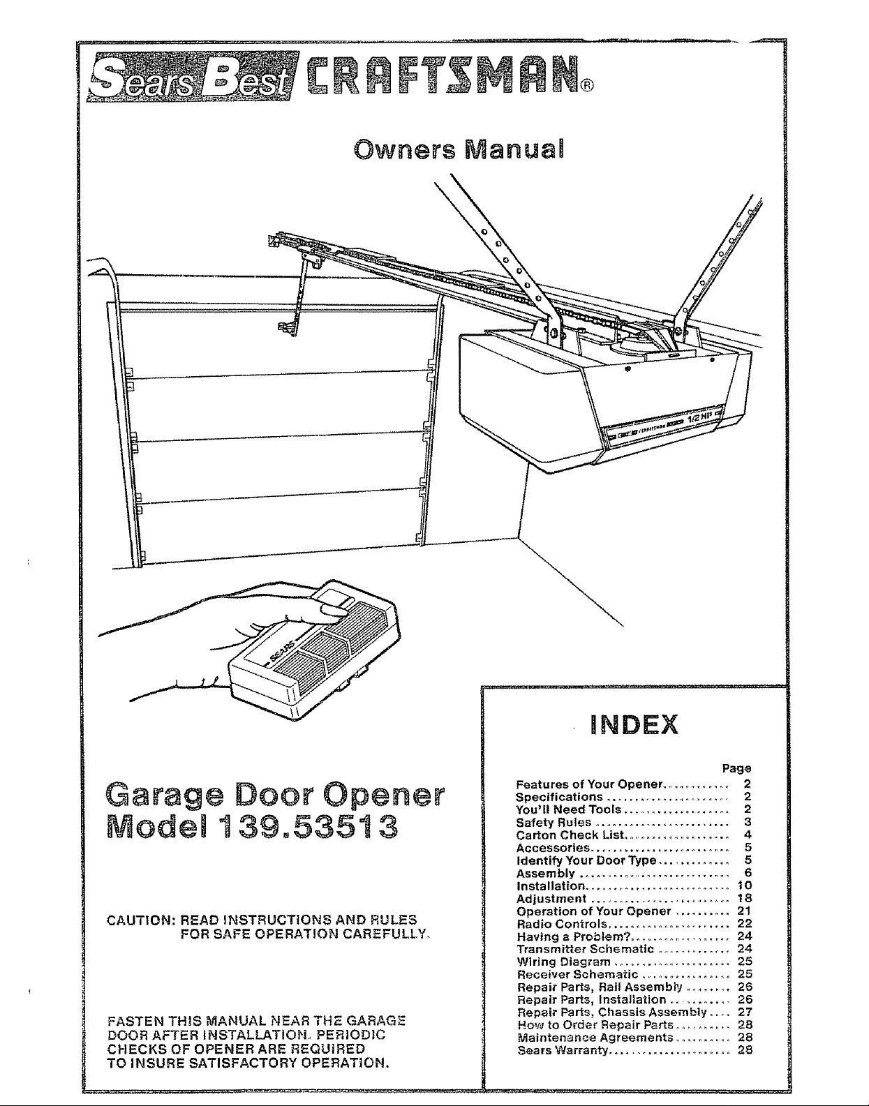
Garage Door Opener
Modem 139.535t 3
CAUTION: READ INSTRUCTIONS AND RULES
FOR SAFE OPERATION CAREFULLY_
FASTEN THIS MANUAL NEAR THE GARAGE
DOOR AFTER INSTALLATIOH. PERIODIC
CHECKS OF OPENER ARE REQUIRED
TO INSURE SATISFACTORY OPERATIOH.
mNDIEX
Page
Features of Your Opener .............. 2
Specifications ........................ 2
You'll Need Tools ................... 2
Safety Rules ........................ 3
Carton Check List .................... 4
Accessories ......................... 5
Identify Your Door Type ............. 5
Assembly ............................. 6
Installation .......................... 10
Adjustment ........................... 18
Operation of Your Opener .......... 21
Radio Controls ....................... 22
Having a Problem? ..................... 24
Transmitter Schematic .............. 24
Wiring Diagram ...................... 25
Receiver Schematic .................. 25
Repair Parts, Rail Assembly .......... 26
Repair Parts, Installation ........... 26
Repair Parts, Chassis Assembly .... 27
How to Order Repair Parts ............. 28
• ]aintenance Agreements ........... 28
Sears Warranty ...................... 28
FEATURES OF YOUR OPENER
1. Opener Lights: Turn on and off automaticaflywith
4-1/2 minute illumination for your safety and con-
venience Provide constant light when Work Light
control button is pressed
2. Safety System: Independent up and down force
adjustment Door reverses automatically when ob-
structed in DOWN direction Door STOPS when
obstructed in UP direction.
3o Emergency Disconnect: Pull cord disconnect
permits manual door operation,
4_ Automatic Reconnect: Trolley halves reconnect
for automatic operation when opener is energized
after emergency discon nect.
5, Motor Power, 1/2 horsepower permanently lubri-
cated motor with automatic reseL
SPECIFICATIONS
MOTOR SAFETY
Type .....
Speed
Volts
Current
Gear reduction
Drive
Lubrication
Length of Travel
Travel rate
Lamp
Door linkage
1t2 horsepower, permanent split capacitor
1500 rpm
120 Volts AC- 60 Hz Only
4 5 amperes
DRIVE MECHANISM
!6:1
Chain & cable with two-piece trolley on
steel Tee rail
Motor is self-lubricated, Drive shaft bronze
oil-fit e bearings
Adjustable to 7-1/2 feet
6 to 8 inches per second
On when door starts in travel, oft 4-t/2
minutes after stop, Also separate Work
Light push button
Adjuslable doer arm Pull cord Irotley
release
6. Digital Radio Controls: 19,683 codes from which to
choose Can be changed easily by the owner
7.3-Channel Transmitter: Three push buttons, Each
button can activate one or more remote control
devices, The large transmitter button is factory
preset to operate the garage door opener_
8. Easy Limit Adjustment: Limits of door opening
and closing adjusted by turning screws without re-
moving chassis cover
9. Vacation Push Button: When the Vacation Push
Button is ON,the opener will not operate from the
transmitter The door will operate in the UP direc-
tion ONLY from the Wall Control (or optional Key
Switch accessory, Page 5).
Persona! Push button & automalic reversal in down
Electronic
Electrical
Limit device .
Limit adjustment
Start circuit
Length (overall) . 12!-t/2 inches
Headroom required 2 inches
Shipping Weight 43 pounds
direction Push button & automatic step tn
up direction
Independent up & down force adjustment
screws
Motor overload protector and low voltage
push button wiring
Circuil actuated by limit nut
Screwdriver adjustment on side panel
Low voltage push button or radio control
DIMENSIONS
YOU' LL N EED TOOLS
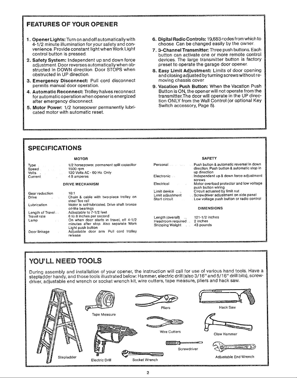
During assembly and installation of your opener, the instruction will call for use of various hand tools. Have a
stepladder handy, and those tools illustrated below: Hammer, electric drill (also 3/16" and 5/16" drill bits), screw-
driver, adjustable end wrench or socket wrench kit, wire cutters, tape measure, pliers and hack saw.
Hack Saw
Claw Hammer
Adlustable End Wrench
Stepladder
Pliers
Tape Measure
Wire Cutters
Screwdriver
Electric Drill Socket Wrench

THIS SAFETY ALERT SYMBOL MEANS CAUTION -- PERSONAL SAFETY OR PROPERTY DAMAGE IN"
STRUCTION,, READ THESE INSTRUCTIONS CAREFULLY,
THIS GARAGE DOOR OPENER IS DESIGNED AND TESTED TO OFFER REASONABLY SAFE SERVICE
PROVIDED IT IS INSTALLED AND OPERATED tN STRICT ACCORDANCE WITH THE FOLLOWING
SAFETY INSTRUCTIONS,
FAILURE TO COMPLY WITH THE FOLLOWING INSTRUCTIONS MAY RESULT IN SERIOUS PERSONAL
INJURY OR PROPERTY DAMAGE
KEEP GARAGE DOOR BALANCED. STICKING
OR BINDING DOORS MUST BE REPAIRED.
GARAGE DOORS, DOOR SPRINGS, CABLES,
PULLEYS, BRACKETS AND THEIR HARDWARE
MAY BE UNDER EXTREME TENSION AND CAN
CAUSE SERIOUS PERSONAL INJURYo DO NOT
ATTEMPT ADJUSTMENTS.. CALL A GARAGE
DOOR SERVICEMAN TO MOVE, LOOSEN OR
ADJUST DOOR SPRINGS OR HARDWARE..
DO NOT WEAR RINGS, WATCHES OR LOOSE
CLOTHING WHILE INSTALLING OR SERVICING
A GARAGE DOOR OPENER°
TO AVOID SERIOUS PERSONAL INJURY FROM
ENTANGLEMENT, REMOVE ALL ROPES CON"
NECTED TO THE GARAGE DOOR BEFORE IN-
STALLING THE GARAGE DOOR OPENER.
DISENGAGE ALL EXISTING GARAGE DOOR
LOCKS TO AVOID DAMAGE TO GARAGE DOOR
DO NOT USE FORCE ADJUSTME NTS TO COM-
PENSATE FOR A BINDING OR STICKING
GARAGE DOOR. EXCESSIVE FORCE WILLtN-
TERFERE WITH THE PROPER OPERATION OF
. THE SAFETY REVERSE SYSTEM OR DAMAGE
THE GARAGE DOOR° (SEE PAGE 19)o
FASTEN THE CAUTION LABEL ON TH E WALL
NEAR THE WALL CONTROL AS A REMINDER
OF SAFE OPERATING PROCEDURES.
INSTALL THE WALL CONTROL (OR ADDITION-
AL PUSH BUTTONS) OUT OF THE REACH OF
CHILDREN, DO NOT ALLOW CHILDREN TO
OPERATE WALL CONTROL OR TRANSMITTER,
SERIOUS PERSONAL INJURY FROM A CLOS-
ING GARAGE DOOR MAY RESULT FROM ANY
MISUSE OF THE OPENER.
INSTALLATION AND WIRING MUST BE IN COM-
PLIANCE WITH LOCAL BUILDING AND ELEC-
TRICAL CODES.
LIGHTWEIGHT DOORS REQUIRE SUBSTAN-
TIAL REINFORCEMENT TO AVOID DOOR
DAMAGE° (SEE PAGE 10)o
THE SAFETY REVERSE SYSTEM TEST IS tM-
PORTANT (SEE PAGE 20),, THE GARAGE DOOR
MUST REVERSE ON CONTACT WITH A ONE-
INCH OBSTACLE PLACED ON THE FLOOR,
FAI LUR E TO PROPERLY ADJ UST THE OPE N E R
MAY RESULT IN SERIOUS PERSONAL INJURY
FROM A CLOSING GARAGE DOOR. REPEAT
TH E TEST AT LEAST ONC E A YEAR AN D MAKE
ANY NEEDED ADJUSTMENTS°
CAUTION: ACTIVATE OPENER ONLY WHEN
THE DOOR IS IN FULL VIEW, FREE OF OB-
STRUCTION AND OPENER IS PROPERLY AD _
JUSTED, NO ONE SHOULD ENTER OR LEAVE
THE GARAGE WHILE DOOR 1S tN MOTION.
DO NOT ALLOW CHILDREN TO PLAY NEAR
DOOR.
USE EMERGENCY RELEASE ONLY TO DIS"
ENGAGE TROLLEY. DO NOT USE RED EMER-
GENCY RE LEASE ROPE AND HANDLE TO PULL
DOOR OPEN OR CLOSED°
DISCONNECT ELECTRIC POWER TO GARAGE
DOOR OPENER BEFORE MAKING REPAIRS
OR REMOVING COVERS°
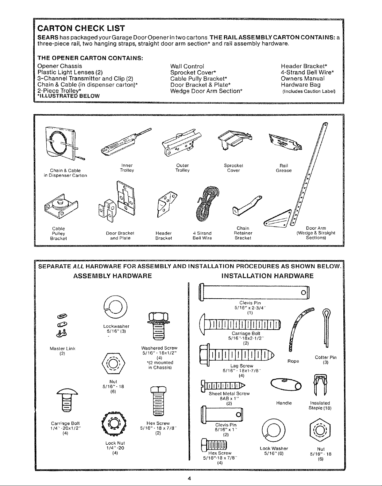
CARTON CHECK LiST
SEARS has packaged your Garage Door Opener in two cartons THE RAILASSEMBLY CARTON CONTAINS: a
three-piece rail, two hanging straps, straight door arm section* and rail assembly hardware
THE OPENER CARTON CONTAINS:
Opener Chassis
Plastic Light Lenses (2)
3-Channel Transmitter and Clip (2)
Chain & Cable (in dispenser carton)*
2-Piece Trolley*
*ILLUSTRATED BELOW
Wall Control
Sprocket Cover*
Cable Pully Bracket*
Door Bracket & Plate*
Wedge Door Arm Section*
Header Bracket*
4-Strand Bell Wire*
Owners Manual
Hardware Bag
(Inetudes Caution Label)
Chain & Cable Trolley
Inner
in Dispenser Carton
Outer
Trolley
Sprocket
Cover
J
Cable
Pulley Door Bracket
Bracket and Plate
SEPARATE ALL HARDWARE FOR ASSEMBLY AND INSTALLATION PROCEDURES AS SHOWN BELOW,
Header 4 S_rand
Bracket Bell Wire
ASSEMBLY HARDWARE
]lqTF[iiilili illD
(_ 5/16" (3)
Master Link
(2)
Lockwasher
@
5/16" - 18
Nut
(e)
Washered Screw
5/16" - 18xl/2"
(4)
"(2 mounted
in Chassis)
"%,[ Carriage Bolt
Chain Door Arm
Retainer (Wedge & Straight
Bracket Sections)
INSTALLATION HARDWARE
Clevis Pin
5/16" x 2,3/4"
(1)
5/16'-18x2,1/2""
(2)
Rope (3)
5/16 "° 18xl-7/8"
(4)
BAB x 1"
(2)
Handle Insulated
Coller Pin
Staple (18)
Carriage Bolt
1/4"-20xl/2"
(4)
@
Lock Nut
1/4"-20
(4)
Hex Screw
5/16 "_ 18 x 7/8'
(2)
Clevis Pin
5/16" x 1 "
(2)
5/16"-18 × 7/8'"
(4)
© @
Lock Washer Nut
5/16"(6) 5/16"- 18
(6)
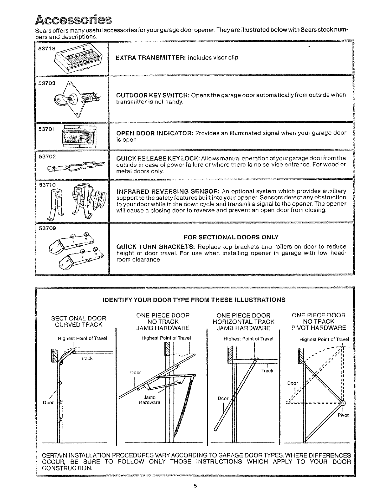
Acc÷ssGries
Sears offers many useful accessories for your garage door open er They are illustrated below with Sears stock num-
bers and descriptions.,
EXTRA TRANSMITTER: Includes visor clip
5371
5370_/C.__r_/_ OUTDOOR KEY SWITCH: Opens the garage door automatically from outside when
transmitter is not handy
53701 _--
....... , ,z. _..........
53702
53709
....... , ,,,,,,,........
OPEN DOOR INDICATOR: Provides an illuminated signal when your garage door
is open,
QUICK RELEASE KEY LOCK: Allows manual operation of your garage door fromthe
outside in case of power failure or where there is no service entrance, For wood or
metal doors only,
INFRARED REVERSING SENSOR: An optional system which provides auxiliary
support to the safety features built into your opener, Sensors detect any obstruction
to your door whi_e in the down cycle and transmit a signal to the opener, The opener
wilt cause a closing door to reverse and prevent an open door from closing,
FOR SECTIONAL DOORS ONI.Y
QUICK TURN BRACKETS: Replace top brackets and rollers on door to reduce
height of door travel, For use when installing opener in garage with Iow head-
room clearance,
IDENTIFY YOUR DOOR TYPE FROM THESE ILLUSTRATIONS
SECTIONAL DOOR
CURVED TRACK
Highest Point of Travel
I
ONE PIECE DOOR
NO TRACK
JAMB HARDWARE
Highest Point of Travel
ONE PIECE DOOR
HORIZONTAL TRACK
JAMB HARDWARE
Highest Point of Travet
Track
ONE PIECE DOOR
NO TRACK
PIVOT HARDWARE
/,
Hardware
t
CERTAIN iNSTALLATION PROCEDURES VARY ACCORDING TO GARAGE DOOR TYPES. WHERE DIFFERENCES
OCCUR, BE SURE TO FOLLOW ONLY THOSE INSTRUCTIONS WHICH APPLY TO YOUR DOOR
CONSTRUCTION,
Door
AssembUy
TO AVOID INSTALLATION DIFFICULTIES, DO NOT RUN THE GARAGE DOOR OPENER UNTIL YOU HAVE
COMPLETED STEP 8, PAGE ! 5.
STE P 1 AssemblereoRa,_AttachCabl_P.,_yBr_okot
, ,=_==,,,,,= ,=, ,,,= .... =,,
TEE RAIL BACK
(TO CHASSIS)
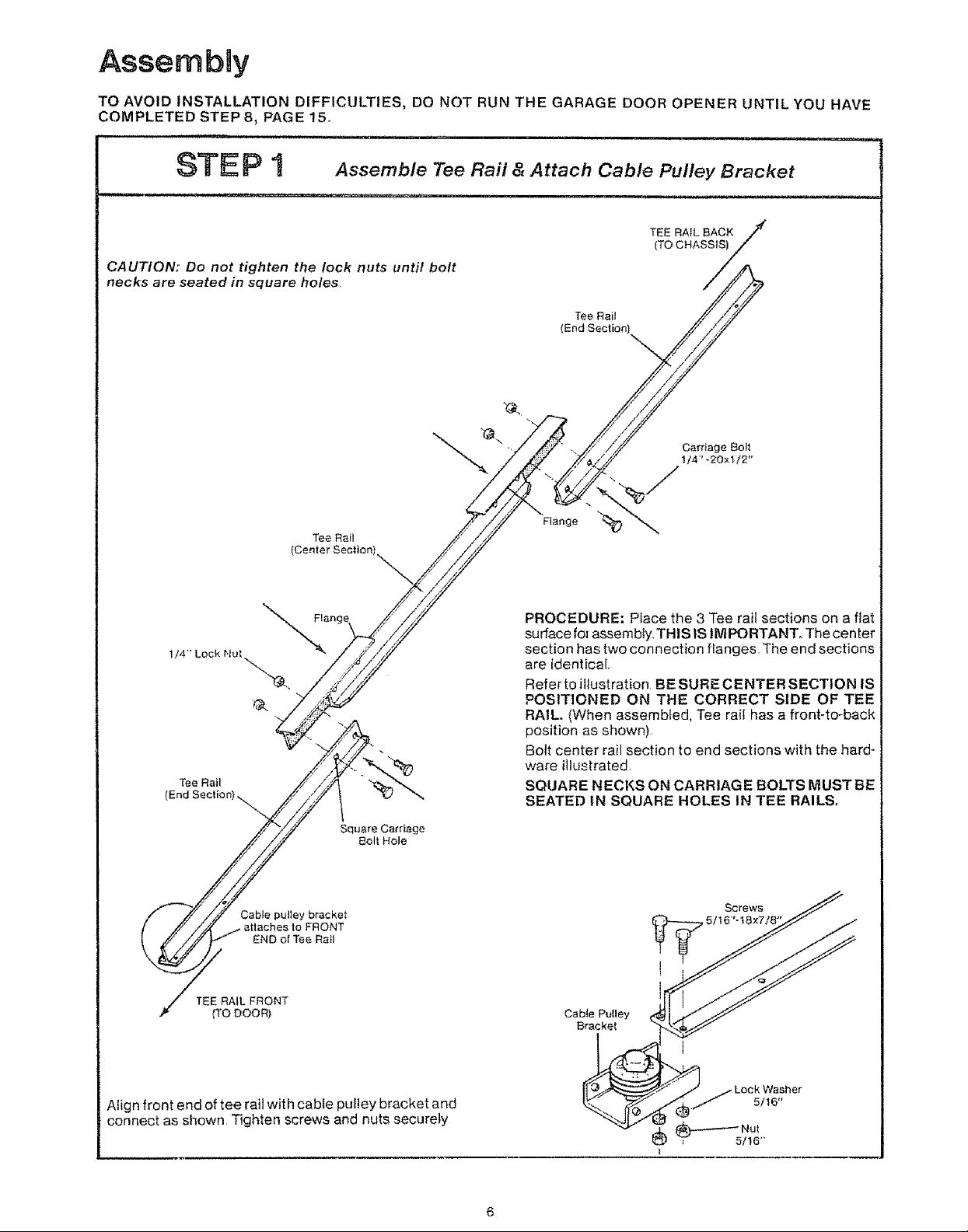
CA UTtON: Do not tighten the lock nuts until bolt
necks are seated in square holes.
TeaRail
(End Section)
\
Carriage Bolt
!/4" -20×1/2"
I14""Lock Nut
Tee Rail
(End Sectior
Tee Rail
(Center
Cable pulley bracket
attaches to FRONT
END of Tee Rail
Square Carriage
Bolt Hole
Flange
PROCEDURE: Ptace the 3 Tee rail sections on a flat
surface fol assembly.. THIS lS IMPORTANT. The center
section has two connection flanges. The end sections
are identical.
Refer to illustration BE SURE CENTER SECTION IS
POSITIONED ON THE CORRECT SIDE OF TEE
RAIL. (When assembled, Tee rail has a front-to-back
position as shown)
Bott center rail section to end sections with the hard-
ware illustrated,
SQUARE NECKS ON CARRIAG E BOLTS MUST BE
SEATED IN SQUARE HOLES IN TEE RAILS,
Screws
TEE RAIL FRONT
(TO DOOR) Cabie Pulley
Align front end of tee rait with cable puItey bracket and
connect as shown Tighten screws and nuts securely
Bracket
Assembmy
STE P 2 connect Trolley & Attach Chain Retainer Bracket
, ..... , _,_,,u,,
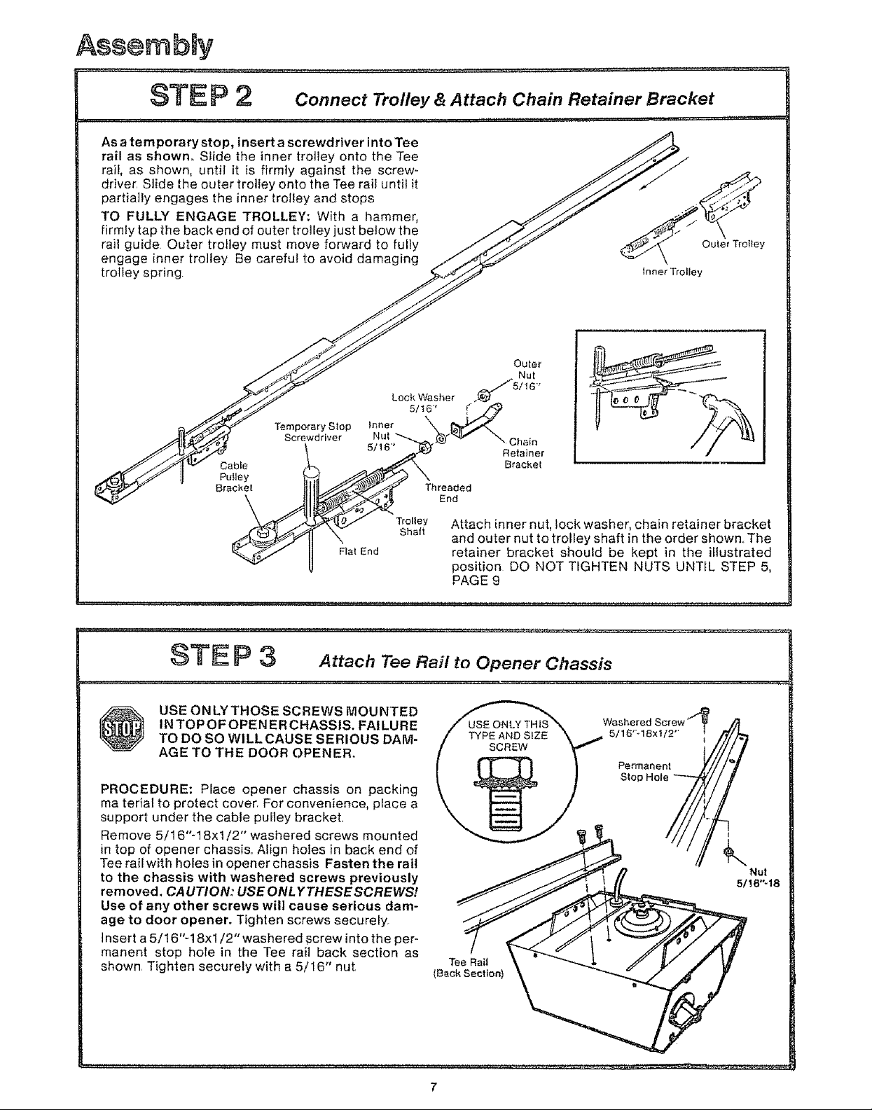
As a temporary stop, insert a screwdriver into Tee
rail as shown° Siide the inner trolley onto the Tee
rail, as shown, until it is firmly against the screw-
driver Slide the outer trolley onto the Tee rail until it
partially engages the inner trolley and stops
TO FULLY ENGAGE TROLLEY; With a hammer,
firmly tap the back end of outer trolley just below the
rail guide Outer trolley must move forward to fully
engage inner trolley Be careful to avoid damaging
trolley spring
_ Outer TrotleY
_nner Trolley
Outer
Nut
Lock Washer ._//5/16"
Cable
PuIley
Bracket
Temporary Stop
Screwdriver
Inner 5/1_
Nut _ Chain
\
Trolley
Shaft
Flat End
USE ON LY THOSE SCREWS MOUNTED
@
PROCEDURE: Place opener chassis on packing
ma terial to protect cover, For convenience, place a
support under the cable pu[]ey bracket.
Remove 5/16"-t 8xt/2" washered screws mounted
in top of opener chassis. Align hotes in back end of
Tee rail with holes in opener chassis Fasten the rail
to the chassis with washered screws previously
rein eve& CA UTION: USE ONLY THESESCREWS!
Use of any other screws will cause serious dam-
age to door opener. Tighten screws securely_
insert a 5/16"-18xl/2" washered screw into the per-
manent stop hole in the Tee rail back section as
shown Tighten securely with a 5/16" nut
IN TOPOF OPENER CHASSIS. FAILURE
TO DO SO WiLL CAUSE SERIOUS DAM-
AGE TO THE DOOR OPENEE
Retainer
Bracket
Threaded
End
Attach inner nut, lock washer, chain retainer bracket
and outer nut to trolley shaft in the order shown.. The
retainer bracket should be kept in the illustrated
position DO NOT TIGHTEN NUTS UNTIL STEP 5,
PAGE 9
Washered Screw 4
5/16"d 8xt/2" _
Permanent _/
Slop Hole_
Nut
5/16"-18
Tee Rail
(Back Section)
7
AssembBy
Cable
LOOl
Notch
Masle_
Master
Outside
B,3r
Flat End
Trofley
ShaN
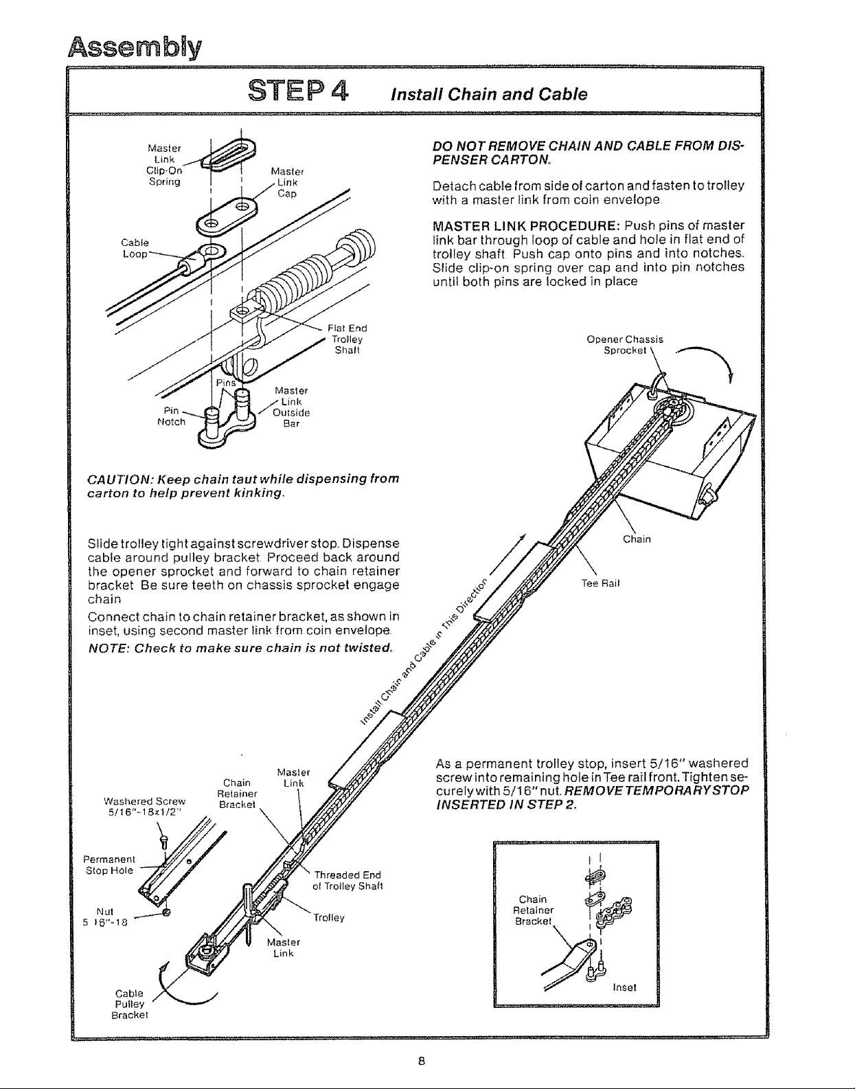
DO NOT REMOVE CHAIN AND CABLE FROM DIS-
PENSER CA RTON.
Detach cable from side of carton and fasten to tro!ley
with a master link from coin envelope
MASTER LINK PROCEDURE: Push pins of master
link bar through loop of cable and hole in flat end of
trolley shaft Push cap onto pins and into notches,
Slide clip-on spring over cap and into pin notches
until both pins are locked in place
Opener Chassis
Sprocket
CAUTION: Keep chain taut while dispensing from
carton to help prevent kinking,
Stide trolley tight against screwdriver stop. Dispense
cable around pulley bracket Proceed back around
the opener sprocket and forward to chain retainer
bracket Be sure teeth on chassis sprocket engage
chain
Connect chain to chain retainer bracket, as shown in
inset, using second master link from coin envelope.
NOTE: Check to make sure chain is not twisted.
Chain
Washered Screw Bracket
5/16"_18×1/2"'
Retainer
Masler
Link
Threaded ;End
of Trolley Shaft
Chain
Tee Rail
As a permanent trolley stop, insert 5/16" washered
screw into remaining hole in Tee rail front, Tighten se-
curely with 5/16" nut. REMOVE TEMPORARYSTOP
INSERTED IN STEP 2_
5 t 6"_18
Cable
Pulley
Bracket
Trolley
Master
Link
AssembRy
STEP 5 tightenthe Chain and Cable
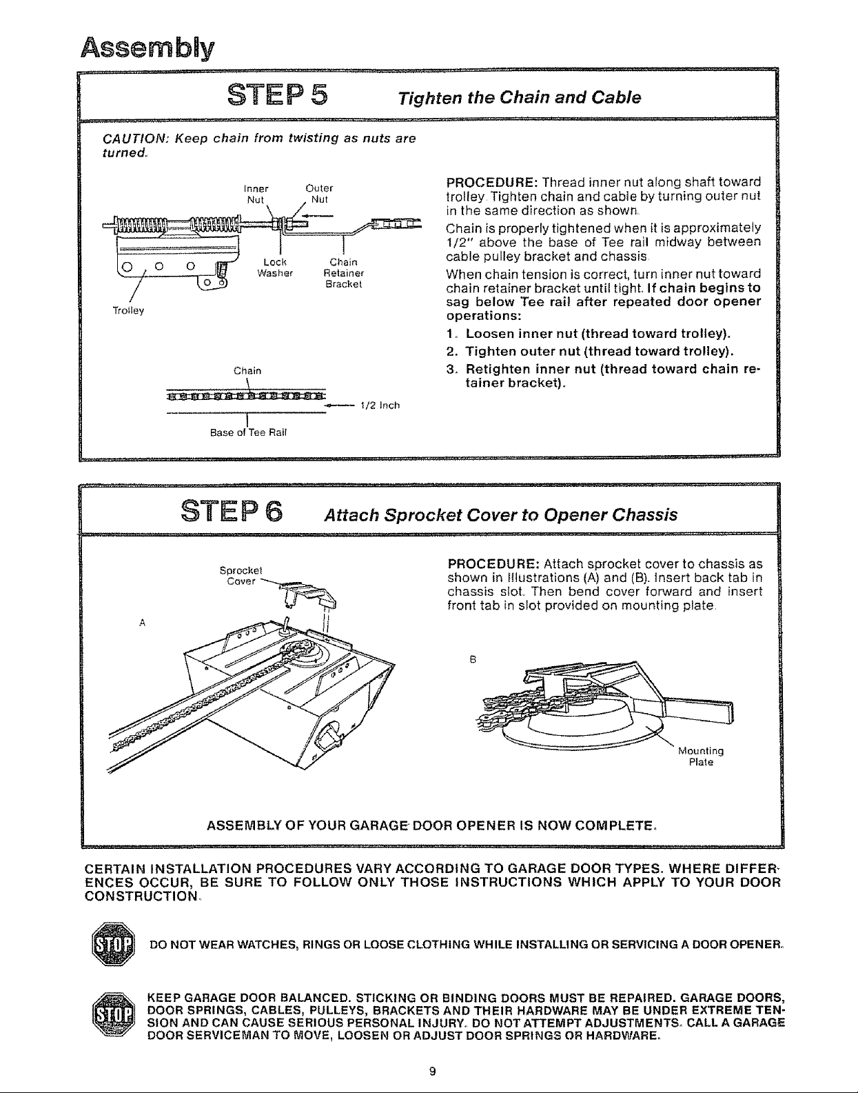
CAUTION: Keep chain from twisting as nuts are
turned,
Trolley
Inner Outer
-T
_ Bracket
Chain
\
-,*------ 1/2 Inch
1
Base of Tee Rail
,r ,, , ,, ,,, ,'_' h/, ' '"'" '"'*"_'"'"""' *H' ............. n'
PROCEDURE: Thread inner nut along shaft toward
trolley Tighten chain and cable by turning outer nut
in the same direction as shown,
Chain is properly tightened when it is approximately
1/2" above the base of Tee rail midway between
cable pulley bracket and chassis
When chain tension is correct, turn inner nut toward
chain retainer bracket until tight, If chain begins to
sag below Tee rail after repeated door opener
operations:
1, Loosen inner nut (thread toward trolley).
2. Tighten outer nut (thread toward trolley).
3, Retighten inner nut (thread toward chain re-
tainer bracket)°
STE P 6 Attach Sprocket Cover to Opener Chassis
Sprocket
Cover _-_
PROCEDURE: Attach sprocket cover to chassis as
shown in Illustrations (A) and (B). Insert back tab in
chassis slot,, Then bend cover forward and insert
front tab in slot provided on mounting plate
Mounting
Plate
ASSEMBLY OF YOUR GARAGE" DOOR OPENER IS NOW COMPLETE°
CERTAIN INSTALLATION PROCEDURES VARY ACCORDING TO GARAGE DOOR TYPES. WHERE DIFFER _
ENCES OCCUR, BE SURE TO FOLLOW ONLY THOSE INSTRUCTIONS WHICH APPLY TO YOUR DOOR
CONSTRUCTION°
DO NOT WEAR WATCHES, RINGS OR LOOSE CLOTHING WHILE INSTALLING OR SERVICING A DOOR OPENER.
KEEP GARAGE DOOR BALANCED. STICKING OR BINDING DOORS MUST BE REPAIRED. GARAGE DOORS,
DOOR SPRINGS, CABLES, PULLEYS, BRACKETS AND THEIR HARDWARE MAY BE UNDER EXTREME TEN-
S|ON AND CAN CAUSE SERIOUS PERSONAL INJURY. DO NOT ATTEMPT ADJUSTMENTS° CALL A GARAGE
DOOR SERVICEMAN TO MOVE, LOOSEN OR ADJUST DOOR SPRINGS OR HARDWARE.
 Loading...