

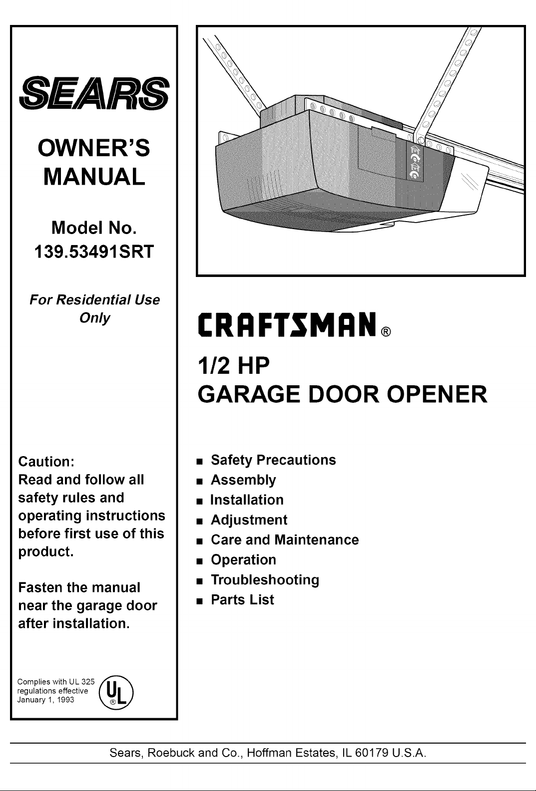
Craftsman 13953491SRT Owner’s Manual
SEARS
OWNER'S
MANUAL
Model No.
139.53491SRT
For Residential Use
Only
Caution:
Read and follow all
safety rules and
operating instructions
before first use of this
product.
Fasten the manual
near the garage door
after installation.
CRRFTSMRN
1/2 HP
GARAGE DOOR OPENER
• Safety Precautions
• Assembly
• Installation
• Adjustment
• Care and Maintenance
• Operation
• Troubleshooting
• Parts List
Complies withUL325 /'1111 _
regulations effective
January 1, 1993
Sears, Roebuck and Co., Hoffman Estates, IL 60179 U.S.A.
Contents
Safety alert symbol review ............................................ 2
Safety information, precautions, tools .......................... 3
Testing your garage door for binding & balance .......... 3
Carton inventory ........................................................... 4
Hardware inventory ....................................................... 5
Illustration of sectional door installation ..................... 6
Illustration of one-piece door installation ..................... 7
Assembly section - pages 8 - 11
Assemble the rail ........................................................ 8
Fasten rail to power unit ............................................ 10
Install the trolley ....................................................... 10
Attach the rail brackets ............................................. 11
Installation section - pages 12 - 27
Installation safety instructions .................................. 11
Determine the header bracket location
Sectional door ......................................................... 12
One-piece door ........................................................ 13
Install the header bracket .......................................... 14
Attach the rail to the header bracket ......................... 15
Safety reversing sensor information ......................... 16
Install the safety reversing sensor ............................. 17
Position the opener .................................................... 19
Hang the opener ........................................................ 20
Install the door control and connect all wires ........... 21
Electrical requirements ............................................. 22
Complete the safety reversing sensor installation .....22
Install the lights and lens .......................................... 23
Attach the emergency release rope and handle .........23
Fasten the door bracket (sectional door) ................... 24
Fasten the door bracket (one-piece door) .................. 25
Connect door arm to trolley (sectional door) ............ 26
Connect door arm to trolley (one-piece door) ........... 27
Adjustment section - pages 28 - 30
Travel limit adjustments ............................................ 28
Force adjustments ..................................................... 29
Test the safety reversing sensor ................................ 30
Test the safety reverse system .................................. 30
Operation safety instructions ...................................... 31
Care of your opener .................................................... 31
Maintenance schedule ................................................. 31
Operation of your opener ............................................ 32
Receiver & remote control programming ................... 33
Troubleshooting .......................................................... 34
Repair parts, rail assembly .......................................... 36
Repair parts, installation ............................................. 36
Repair parts, power unit .............................................. 37
Accessories ................................................................. 38
Index ........................................................................... 39
How to order repair parts ............................................ 40
Warranty ...................................................................... 40
Start by reviewing these important safety alert symbols:
When you see these Safety Symbols on the following pages, they will alert you to the possibility of serious injury
or death if you do not comply with the corresponding instructions. The hazard may come from something
mechanical or from electric shock. Read the instructions carefully.
Mechanical Electrical
When you see this Safety Symbol on the following pages, it will alert you to the possibility of damage to your
garage door and/or the garage door opener if you do not comply with the corresponding instructions. Read the
instructions carefully.
iiii iiiiiiii iiii
This garage door opener is designed and tested to offer safe service provided it is installed, operated, maintained
and tested in strict accordance with the safety instructions contained in this manual.
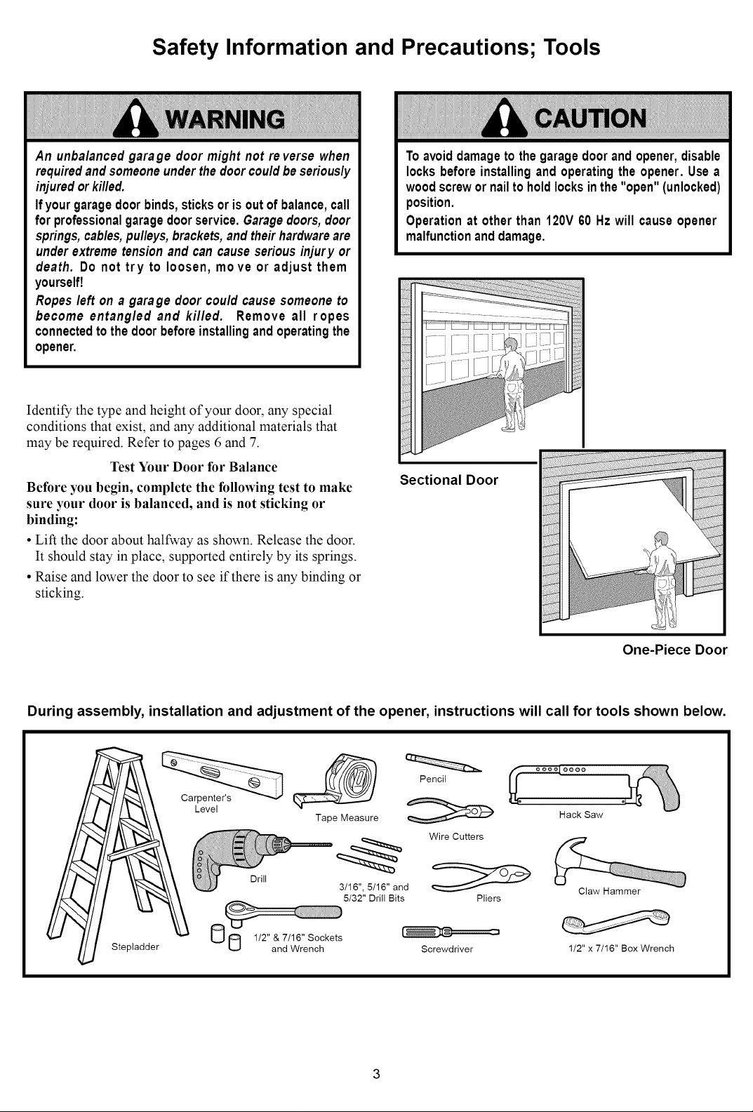
Safety Information and Precautions; Tools
An unbalancedgarage door might not reverse when
requiredand someoneunderthedoorcouldbeseriously
injuredorkilled.
Ifyourgaragedoorbinds,sticksoris outof balance,call
for professionalgaragedoorservice.Garagedoors,door
springs,cables,pulleys,brackets,andtheirhardwareare
underextreme tensionand cancause seriousinjury or
death. Do not try to loosen, move or adjust them
yourself!
Ropesleft on a garage door could causesomeone to
become entangled and killed. Remove all ropes
connectedtothedoorbeforeinstallingand operatingthe
opener.
Identify the type and height of your door, any special
conditions that exist, and any additional materials that
may be required. Refer to pages 6 and 7.
Test Your Door for Balance
Before you begin, complete the following test to make
sure your door is balanced, and is not sticking or
binding:
• Lift the door about halfway as shown. Release the door.
It should stay in place, supported entirely by its springs.
• Raise and lower the door to see if there is any binding or
sticking.
Toavoiddamageto thegaragedoorand opener,disable
locksbeforeinstallingand operatingthe opener.Use a
woodscrewornailto holdlocksinthe "open" (unlocked)
position.
Operationat otherthan 120V 60 Hz will causeopener
malfunctionanddamage.
Sectional Door
One-Piece Door
During assembly, installation and adjustment of the opener, instructions will call for tools shown below.
Pencil
Stepladder
Level
Drill
Tape Measure
3/16", 5/16" and
5/32" Drill Bits
Wire Cutters
Pliers
Screwdriver
Hack Saw
Claw Hammer
1/2" x 7/16" Box Wrench
Carton Inventory
Your garage door opener is packaged in one carton which contains the power unit and all parts illustrated below. If anything
is missing, carefully check the packing material. Parts may be "stuck" in the foam. KEEP THE FOAM INTACT (see page
10). Hardware for assembly and installation is shown on page 5.
Sprocket
Coupling
Three-Function Remote Control
Standard
Control Console
Rail Support
with Visor Clip (2)
Light Lens
2-Conductor Bell Wire
I__) I_
0._ 6/
_1_
iq? iq,
Hanging Brackets
White & White/Red
Header Bracket
Braces_
Header/Rail
Brackets
Door Bracket Plate
©
Door Bracket
Assembly
Straight Door
Arm Section
Rail
(2) Safety Reversing Sensors
(1 Sending Eye and 1 Receiving Eye)
2-Conductor White & White/Black Bell Wire
with attached
Safety Reversing Sensor
Mounting Bracket
With Square Holes (2)
I
"C" Wrap (2)
Curved Door
Arm Section
Safety Reversing Sensor
Mounting Bracket
With Slot (2)
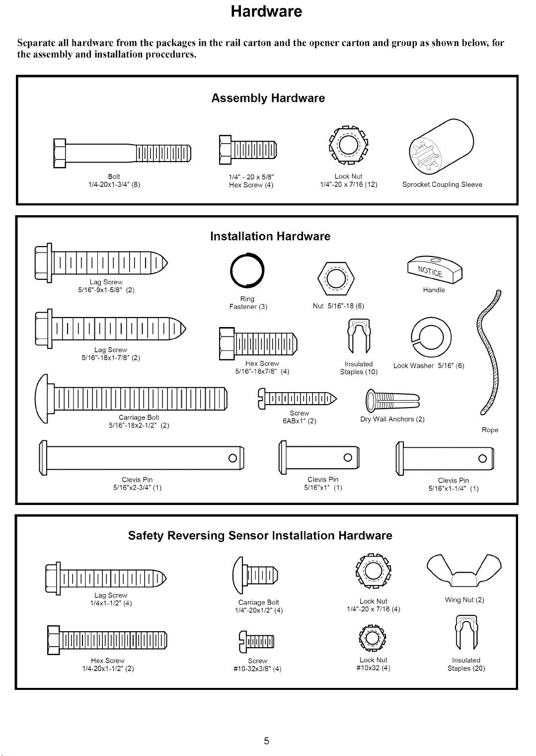
Hardware
Separate all hardware from the packages in the rail carton and the opener carton and group as shown below, for
the assembly and installation procedures.
Assembly Hardware
lllllllll/ RllllllID
Bolt 1/4" - 20 x 5/8"
1/4-20xl-3/4" (8) Hex Screw (4)
Installation Hardware
_ ] ] ] laglSclew] ] I _ O
5/16"-9xl-5/8" (2)
111111111111 >
Lag Screw
5/16"-18xl-7/8" (2)
Carriage Bolt 6ABxl" (2) Dry Wall Anchors (2)
5/16"-18x2-1/2" (2)
Ring
Fastener (3)
Hex Screw
5/16"-18x7/8" (4)
@
Lock Nut
1/4"-20 x 7/16 (12) Sprocket Coupling Sleeve
Handle
Nut 5/16"-18 (6)
Insulated
Staples (10)
Lock Washer 5/16" (6)
Rope
o] oH
Clevis Pin Clevis Pin
5/16"x2-3/4" (1) 5/16"x1" (1)
Safety Reversing Sensor Installation Hardware
©
Lag Screw
1/4x1-1/2" (4)
Hex Screw Screw Lock Nut
1/4-20xl -1/2" (2) #10-32x3/8" (4) #10x32 (4)
Carriage Bolt Lock Nut
1/4"-20xl/2" (4) 1/4"-20 x 7/16 (4)
Clevis Pin
5/16"x1-1/4" (1)
Wing Nut (2)
Insulated
Staples (20)
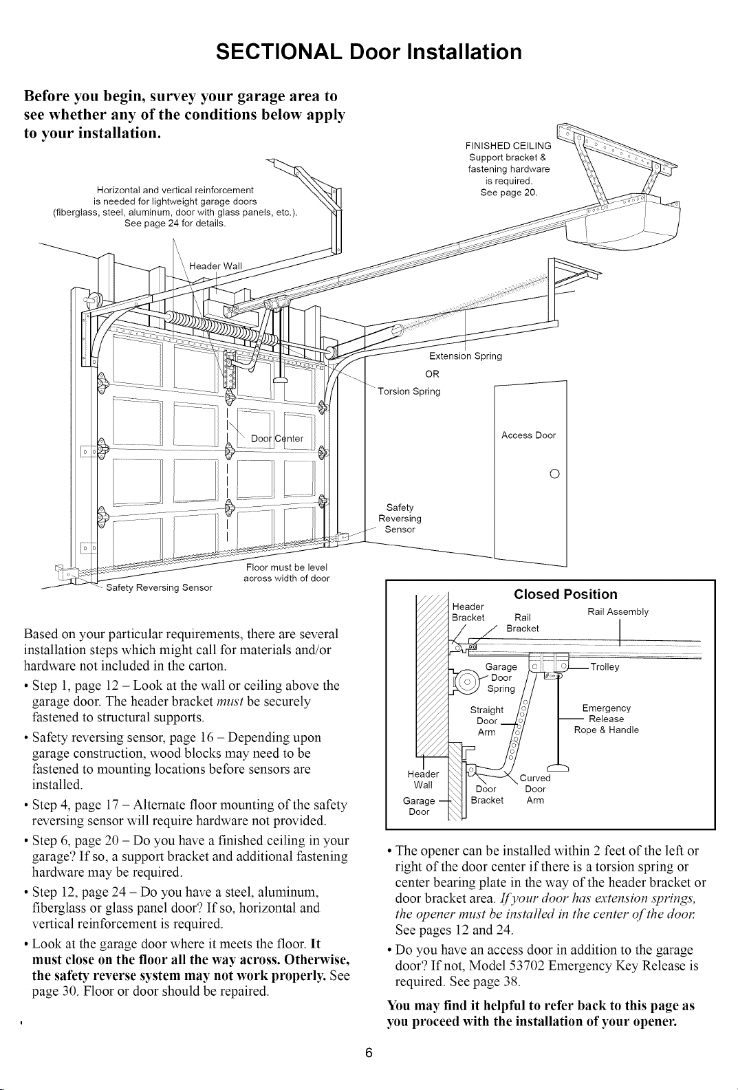
SECTIONAL Door Installation
Before you begin, survey your garage area to
see whether any of the conditions below apply
to your installation.
Horizontal and vertical reinforcement
is needed for lightweight garage doors
(fiberglass, steel, aluminum, door with glass panels, etc.).
See page 24 for details.
Header Wall
FINISHED CEILING
Support bracket &
fastening hardware
is required.
See page 20.
Extension Spring
OR
Torsion Spring
Access Door
Floor must be level
across width of door
Safety Reversing Sensor
Based on your particular requirements, there are several
installation steps which might call for materials and/or
hardware not included in the carton.
• Step 1, page 12 - Look at the wall or ceiling above the
garage door. The header bracket must be securely
fastened to structural supports.
• Safety reversing sensor, page 16 - Depending upon
garage construction, wood blocks may need to be
fastened to mounting locations before sensors are
installed.
• Step 4, page 17 - Alternate floor mounting of the safety
reversing sensor will require hardware not provided.
• Step 6, page 20 - Do you have a finished ceiling in your
garage'? If so, a support bracket and additional fastening
hardware may be required.
• Step 12, page 24 - Do you have a steel, aluminum,
fiberglass or glass panel door'? If so, horizontal and
vertical reinforcement is required.
• Look at the garage door where it meets the floor. It
must close on the floor all the way across. Otherwise,
the safety reverse system may not work properly. See
page 30. Floor or door should be repaired.
O
Safety
Reversing
Sensor
Closed Position
Header
Bracket Rail Rail Assembly
_/ Bracket ................................
Garage Trolley
_'(o3Y"Door / /
SpringlJ I
Straight /?/ I Emergency
Door __._7/ I_ Fpe&Han--oReleasedle
J.
Header
Wall
Garage --
Door
• The opener can be installed within 2 feet of the left or
right of the door center if there is a torsion spring or
center bearing plate in the way of the header bracket or
door bracket area. [[):our door has extension springs',
the opener must be installed in the center of the dooe
See pages 12 and 24.
• Do you have an access door in addition to the garage
door'? If not, Model 53702 Emergency Key Release is
required. See page 38.
You may find it helpful to refer back to this page as
you proceed with the installation of your opener.
_ Curve_--
_1 Door "Door
_ Bracket Arm
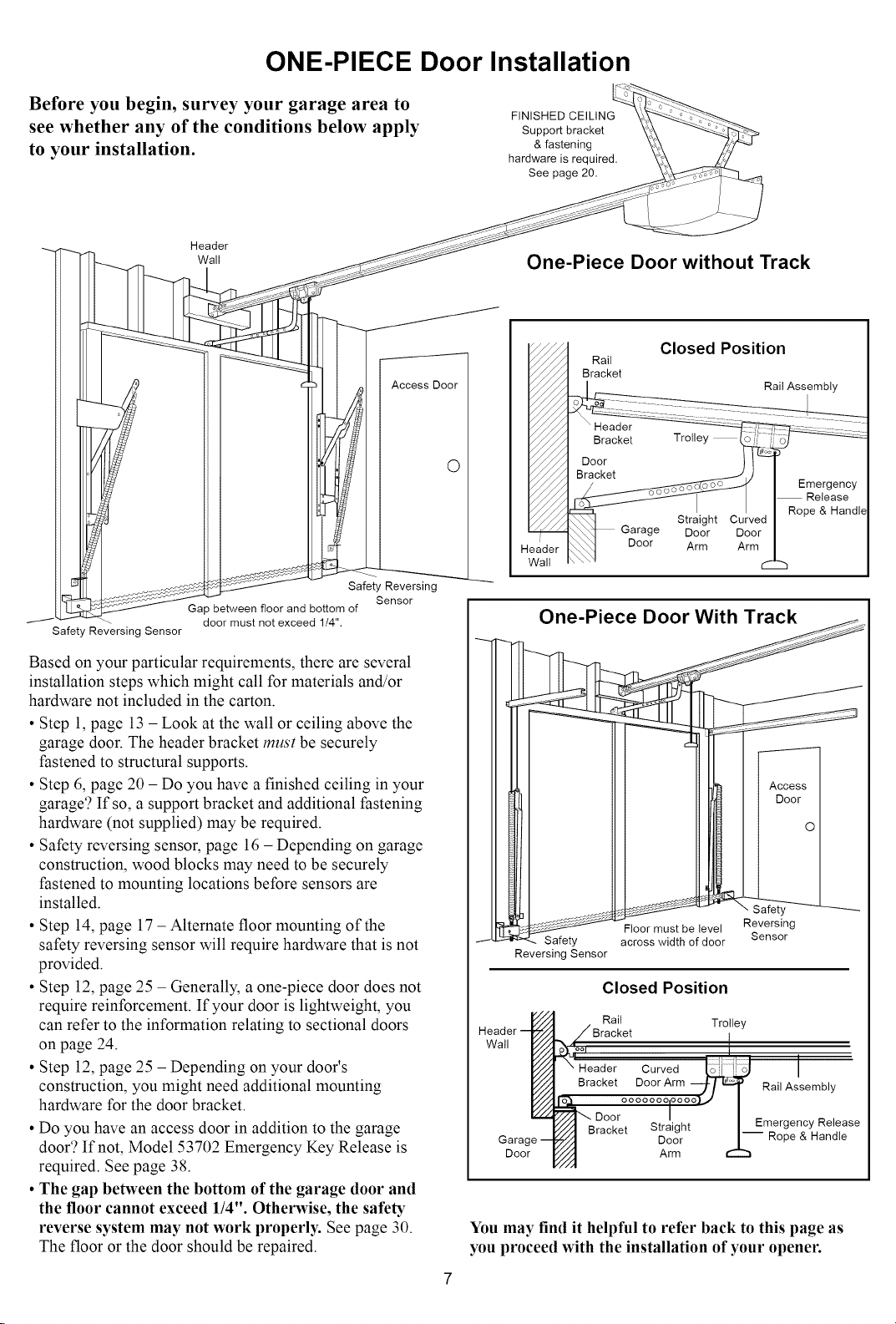
ONE-PIECE Door Installation
Before you begin, survey your garage area to
see whether any of the conditions below apply
to your installation.
Header
Wall
Access Door
Safety Reversing
Sensor
Safety Reversing Sensor
Ga _ between floor and bottom of
door must not exceed 1/4",
FINISHED CEILING
Support bracket
& fastening
hardware is required.
See page 20.
One-Piece Door without Track
Rail
Bracket
O
Closed Position
Rail Assembly
Garage Door
Door Arm
Based on your particular requirements, there are several
installation steps which might call for materials and/or
hardware not included in the carton.
• Step 1, page 13 - Look at the wall or ceiling above the
garage door. The header bracket must be securely
fastened to structural supports.
• Step 6, page 20 - Do you have a finished ceiling in your
garage'? If so, a support bracket and additional fastening
hardware (not supplied) may be required.
• Safety reversing sensor, page 16 - Depending on garage
construction, wood blocks may need to be securely
fastened to mounting locations before sensors are
installed.
• Step 14, page 17 - Alternate floor mounting of the
safety reversing sensor will require hardware that is not
provided.
• Step 12, page 25 - Generally, a one-piece door does not
require reinforcement. If your door is lightweight, you
can refer to the information relating to sectional doors
on page 24.
• Step 12, page 25 - Depending on your door's
construction, you might need additional mounting
hardware for the door bracket.
• Do you have an access door in addition to the garage
door'? If not, Model 53702 Emergency Key Release is
required. See page 38.
• The gap between the bottom of the garage door and
the floor cannot exceed 1/4". Otherwise, the safety
reverse system may not work properly. See page 30.
The floor or the door should be repaired.
:_if__ust be level Reversing
_ _dih ofdoor Sensor
Reversing Sensor
Reversing
Sensor
Closed Position
Header
Wall
Door Arm
Rail Trolley
Header _ o z.-,_..._-,,-Curved I
Bracket
_/_ Rail Assembly
-- O000000lO000
- Door °°::;j:°°°'J I EmergencyReleasel
Bracket _ralgm I--
Door I-- Rope & Handle
You may find it helpful to refer back to this page as
you proceed with the installation of your opener.
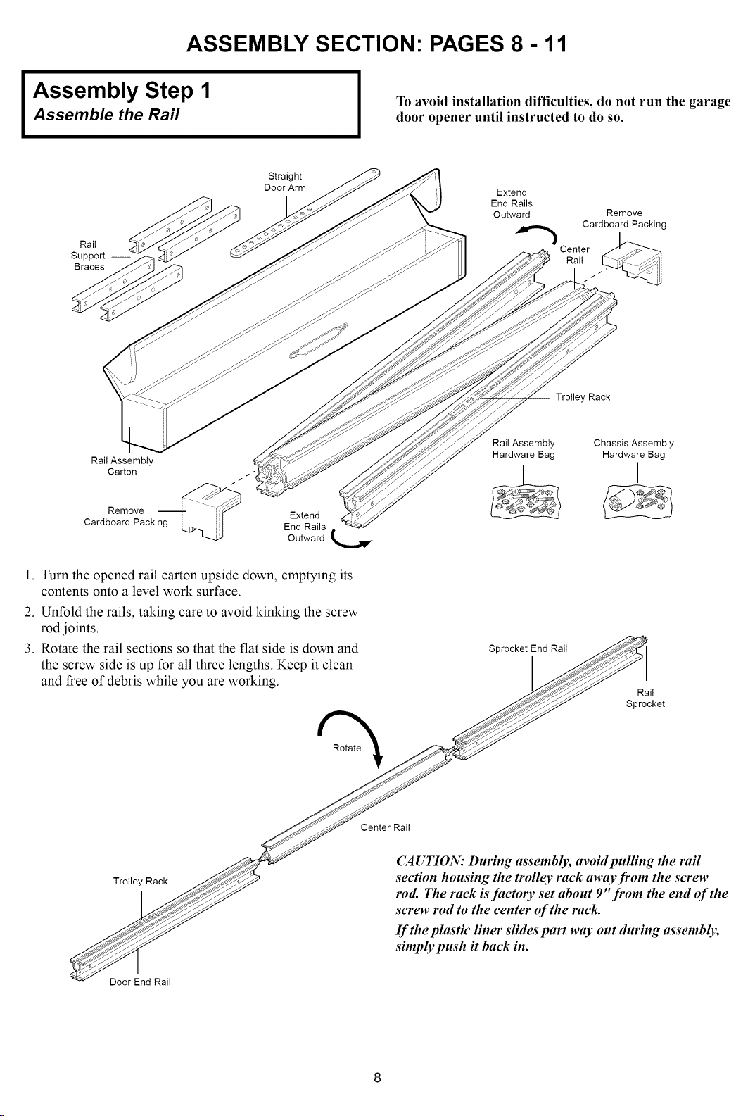
ASSEMBLY SECTION" PAGES 8 - 11
Assembly Step 1
Assemble the Rail
Rail
Support --
Braces
Rail Assembly (
Carton _ _"
Straight
Door Arm
To avoid installation difficulties, do not run the garage
door opener until instructed to do so.
Extend
End Rails
Outward
Center
Trolley Rack
Rail Assembly
Hardware Bag
Remove
Cardboard Packing
Rail
Chassis Assembly
Hardware Bag
Remove
Cardboard Packing
Extend
End Rails
Outward
1. Turn the opened rail carton upside down, emptying its
contents onto a level work surface.
2. Unfold the rails, taking care to avoid kinking the screw
rod joints.
3. Rotate the rail sections so that the flat side is down and
the screw side is up for all three lengths. Keep it clean
and free of debris while you are working.
Trolley Rack
Sprocket End Rail
Rail
Sprocket
Center Rail
CAUTION: During assembly, awdd pulling the rail
section housing the trolley rack away from the screw
rod. The rack is facto1T set about 9"from the end of the
screw rod to the center of the rack.
If the plastic liner slides part way out during assembly,
simply push it back in.
DoorEnd Rail
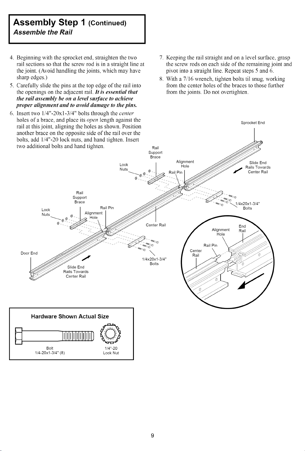
Assembly Step 1 (Continued)
Assemble the Rail
4. Beginning with the sprocket end, straighten the two
rail sections so that the screw rod is in a straight line at
the joint. (Avoid handling the joints, which may have
sharp edges.)
5. Carefully slide the pins at the top edge of the rail into
the openings on the adjacent rail. It is essential that
the rail assembly be on a level smfaee to achieve
proper alignment and to aw_id damage to the pins.
6. Insert two 1/4"-20xl-3/4" bolts through the center
holes of a brace, and place its open length against the
rail at this joint, aligning the holes as shown. Position
another brace on the opposite side of the rail over the
bolts, add 1/4"-20 lock nuts, and hand tighten. Insert
two additional bolts and hand tighten.
Lock Hole Rails Towards
Nuts Center Rail
Rail )__ _ _--_'---_
Support
Brace 1/4x2Ox1-3/4"
Lock Rail Pin Bolts
Nuts Alignment
7. Keeping the rail straight and on a level surface, grasp
the screw rods on each side of the remaining joint and
pivot into a straight line. Repeat steps 5 and 6.
8. With a 7/16 wrench, tighten bolts til snug, working
from the center holes of the braces to those further
from the joints. Do not overtighten.
Sprocket End
Rail
Support
Brace
Alignment Slide End
@-- - - - Center Rail
Door End
_ _" 1/4x20x 1-3/4"
Slide End
Rails Towards
Center Rail
Hardware Shown Actual Size
D
Bolt 1/4"-20
1/4-20xl-3/4" (8) Lock Nut
illllllll} @
Bolts
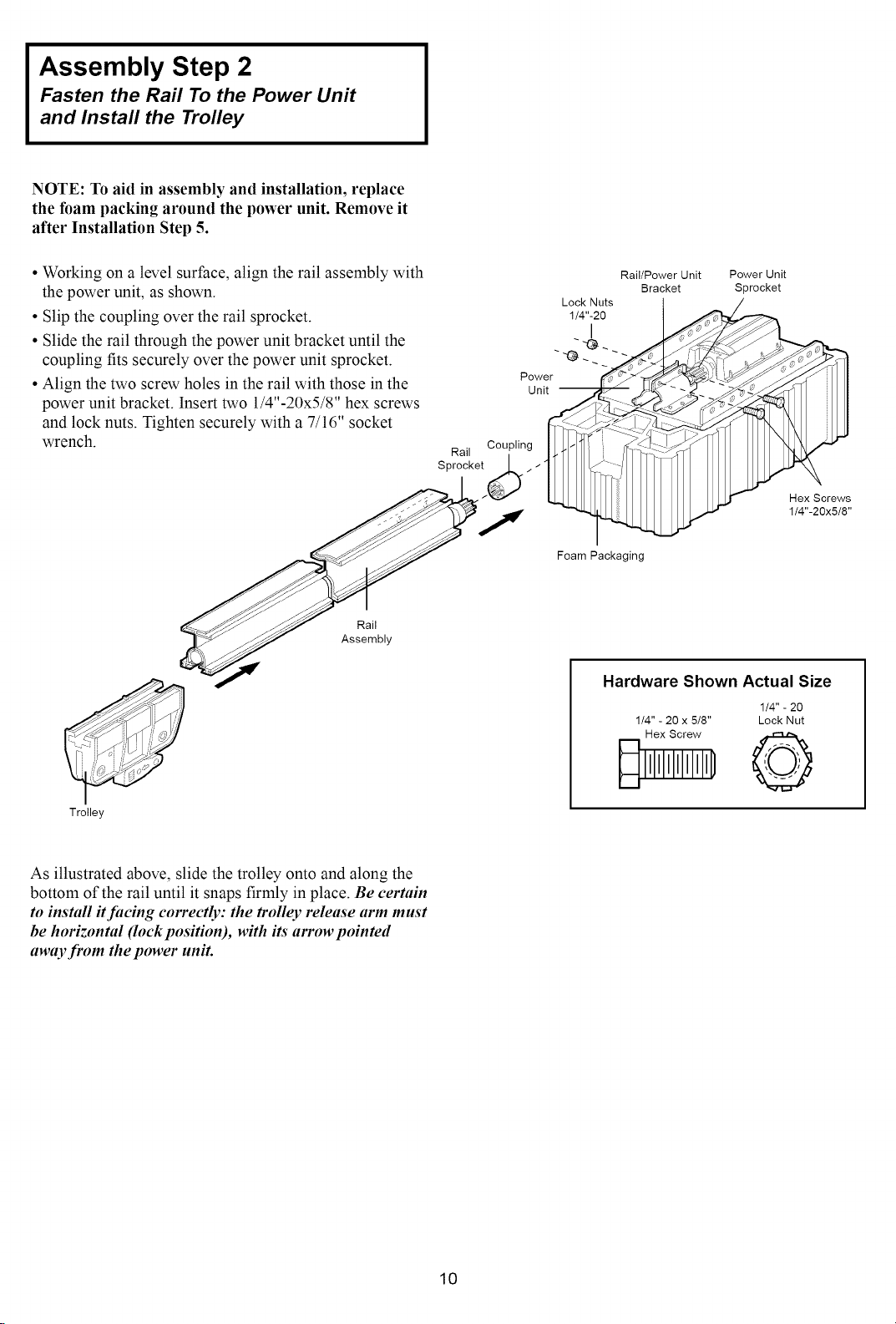
Assembly Step 2
Fasten the Rail To the Power Unit
and Install the Trolley
NOTE: To aid in assembly and installation, replace
the foam packing around the power unit. Remove it
after Installation Step 5.
• Working on a level surface, align the rail assembly with
the power unit, as shown.
• Slip the coupling over the rail sprocket.
• Slide the rail through the power unit bracket until the
coupling fits securely over the power unit sprocket.
• Align the two screw holes in the rail with those in the
power unit bracket. Insert two 1/4"-20x5/8" hex screws
and lock nuts. Tighten securely with a 7/16" socket
wrench.
Rail
Assembly
Rail/Power Unit
Bracket
Lock Nuts
1/4"-20
I
Foam Packaging
Hardware Shown Actual Size
1/4" - 20 x 5/8" Lock Nut
Power Unit
Sprocket
/
//
/
J
_" Hex Screws
1/4"-20x5/8"
1/4"- 20
Trolley
As illustrated above, slide the trolley onto and along the
bottom of the rail until it snaps firmly in place. Be certain
to install #facing correctly: the trolley release arm must
be horizontal (lock position), with its arrow pointed
away from the power unit.
D;Ix,sI:;,D@
10
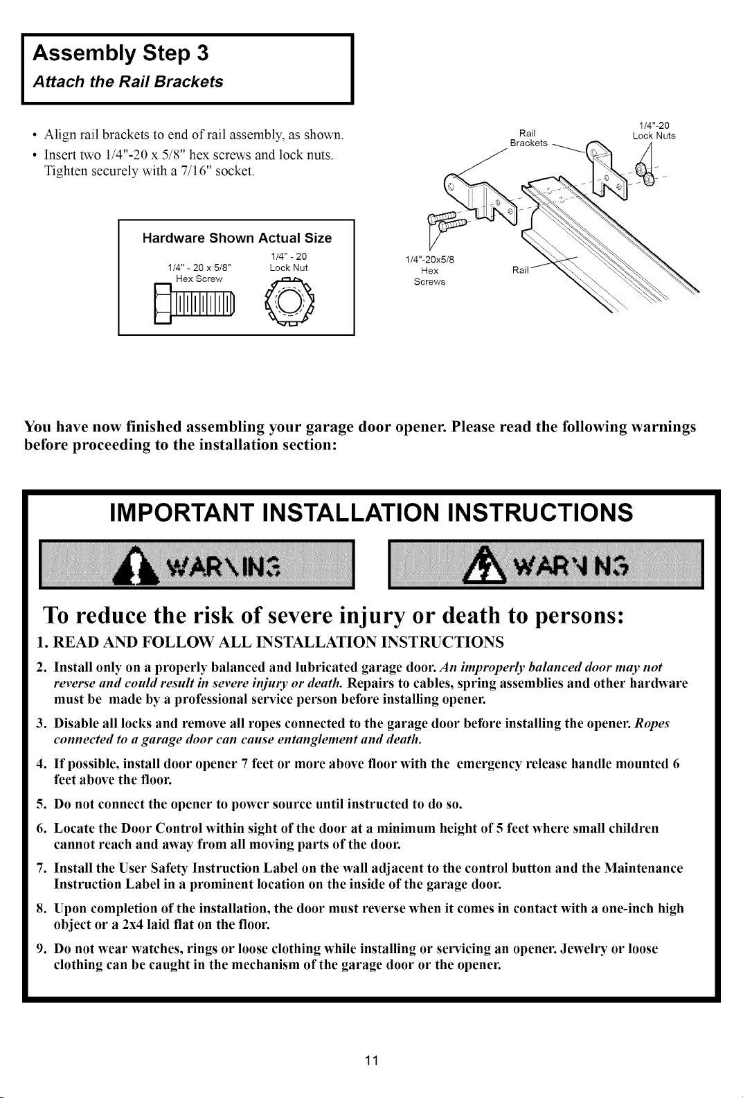
Assembly Step 3
Attach the Rail Brackets
• Align rail brackets to end of rail assembly, as shown.
Rail
Brackets
1/4"-20
Lock Nuts
• Insert two 1/4"-20 x 5/8" hex screws and lock nuts.
Tighten securely with a 7/16" socket.
Hardware Shown Actual Size
1/4" - 20 x 5/8" Lock Nut
1/4" - 20
1/4"-20x5/8
Hex
Screws
You have now finished assembling your garage door opener. Please read the following warnings
before proceeding to the installation section:
IMPORTANT INSTALLATION INSTRUCTIONS
To reduce the risk of severe injury or death to persons:
1. READ AND FOLLOW ALL INSTALLATION INSTRUCTIONS
2. Install only on a properly balanced and lubricated garage door. An improperly balanced door may not
reverse and could result in severe injuly or death. Repairs to cables, spring assemblies and other hardware
must be made by a professional service person before installing opener.
3. Disable all locks and remove all ropes connected to the garage door before installing the opener. Ropes
connected to a garage door can cause entanglement and death.
4. If possible, install door opener 7 feet or more above floor with the emergency release handle mounted 6
feet above the floor.
5. Do not connect the opener to power source until instructed to do so.
6. Locate the Door Control within sight of the door at a minimum height of 5 feet where small children
cannot reach and away from all moving parts of the door.
7. Install the User Safety Instruction Label on the wall adjacent to the control button and the Maintenance
Instruction Label in a prominent location on the inside of the garage door.
8. Upon completion of the installation, the door must reverse when it comes in contact with a one-inch high
object or a 2x4 laid flat on the floor.
9. Do not wear watches, rings or loose clothing while installing or servicing an opener. Jewelry or loose
clothing can be caught in the mechanism of the garage door or the opener.
11
INSTALLATION SECTION" PAGES 12- 27
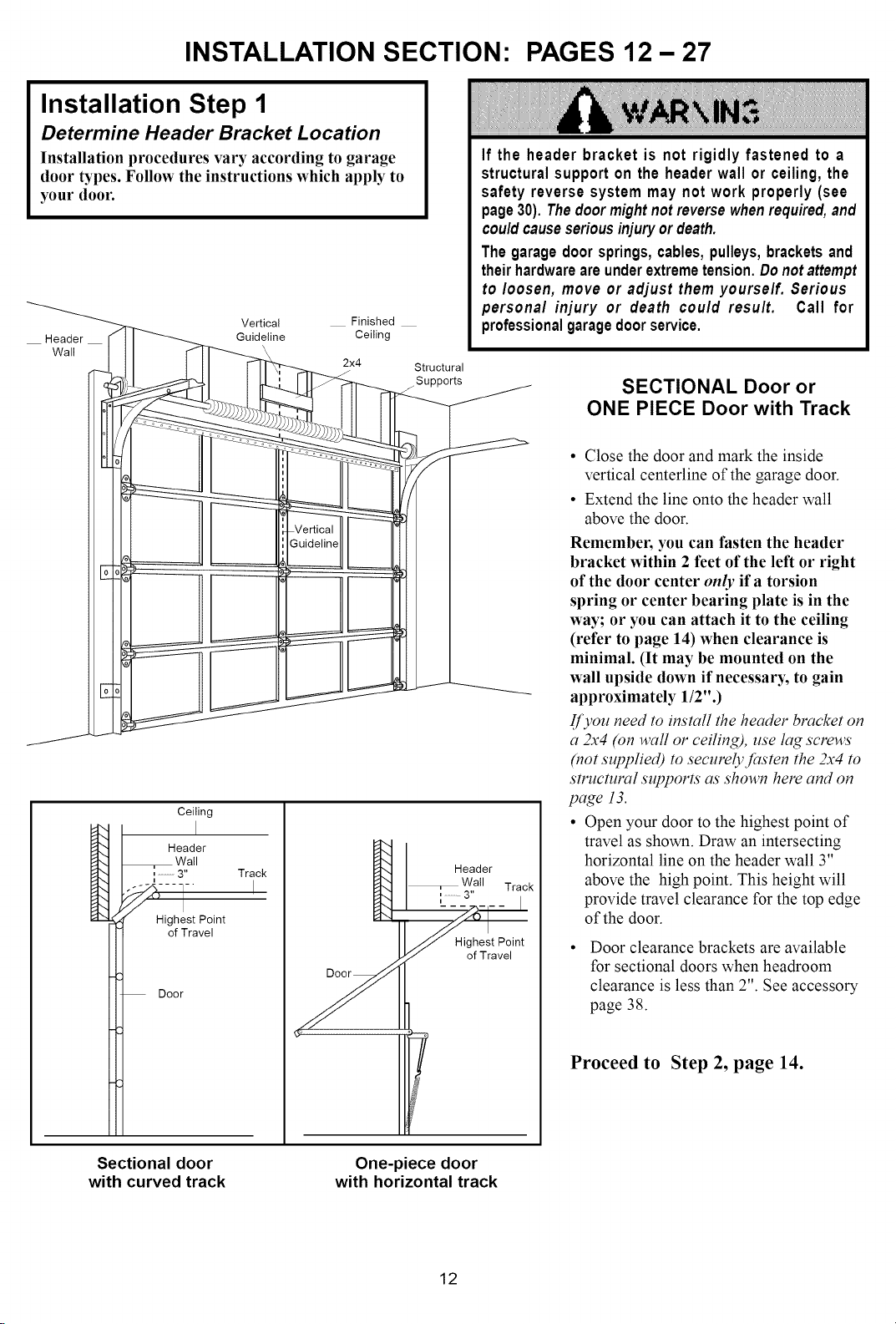
Installation Step 1
Determine Header Bracket Location
Installation procedures vary according to garage
door types. Follow the instructions which apply to
your door.
Vertical Finished
Header
Wall
Ceiling
Header
Wall
,,............3" Track
Highest Point
of Travel
Door
Guideline Ceiling
2x4
I
Structural
If the header bracket is not rigidly fastened to a
structuralsupport on the headerwall or ceiling, the
safety reverse system may not work properly (see
page30). Thedoormightnotreversewhenrequired,and
couldcauseseriousinjuryordeath.
The garagedoor springs,cables,pulleys,bracketsand
theirhardwareareunderextremetension.Do notattempt
to loosen, move or adjust them yourself. Serious
personal injury or death could result. Call for
professionalgaragedoorservice.
SECTIONAL Door or
ONE PIECE Door with Track
• Close the door and mark the inside
vertical centerline of the garage door.
• Extend the line onto the header wall
above the door.
Remember, you can fasten the header
bracket within 2 feet of the left or right
of the door center only if a torsion
spring or center bearing plate is in the
way; or you can attach it to the ceiling
(refer to page 14) when clearance is
minimal. (It may be mounted on the
wall upside down if necessary, to gain
approximately 1/2".)
If you need to install the header bracket on
a 2x4 (on waft or ceiling), use lag screws
(not supplied) m securelyJasten the 2x4 m
structural supports as shown here and on
page 13.
• Open your door to the highest point of
travel as shown. Draw an intersecting
horizontal line on the header wall 3"
above the high point. This height will
provide travel clearance for the top edge
of the door.
Highest Point
of Travel
Door clearance brackets are available
for sectional doors when headroom
clearance is less than 2". See accessory
page 38.
Sectional door
with curved track
Proceed to Step 2, page 14.
One-piece door
with horizontal track
12
 Loading...