

Page 1
smm/mȥismm.
MODELS:
Garage
Door
Opener
139.53403
139.53413
139.53606
139.53610
1/3 HP
1/2 HP
1/2 HP
1/3 HP
Owners Manual
CAUTION
READ INSTRUCTiONS AND RULES
FOR SAFE OPERATION CAREFULLY
CONTENTS PAGE
Features of Your Opener
Specifications
Accessories
Carton Check List......
You’!i Need Tools
Safety Rules
Operation of Your Opener
Maintenance Schedule
Assembly.....
Installation information..................... 9
Installation
Force & Limit Adjustment.............. 17
Safety Reverse Test —............
Setting/Changing Code
Having a Problem?
Repair Parts, Rail Assembly........... 22
Repair Parts, Installation
Repair Parts, Chassis Assembly —, 23
How to Order Repair Parts.............. 24
Maintenance Agreements—. —.. 24
Sears Warranty
........... 2
...
.................................. 2
....................................
......................................
........................................
..............................
..................
......................
..............................
..... 5
..................
.......
...................
........................
-------------
2
3
3
4
5
6
9
18
19
20
22
24
FASTEN OWNERS MANUAL NEAR GARAGE DOOR AFTER INSTALLATION IS COMPLETE.
PERIODIC CHECKS OF THE OPENER ARE REQUIRED TO INSURE SATISFACTORY OPERATION.
Page 2

FEATURES OF YOUR OPENER
1. Motor; Permanently lubricated with automatic
reset
2. Opener Light; Turns on and off automatically.
Provides4-1/2 minute illumination foryoursafety
and convenience.
3. Safety System: Independent up and down force
adjustment Door reverses automatically when
obstructed in DOWN direction Door STOPS when
obstructed in UP direction
4. Easy Limit Adjustment: Limits of door opening
and closing adjusted by turning screws without
removing chassis cover.
SPECIFiCATlONS
MOTOR
Type ..
speed
Volts .
Current
Gears
....................
Drive .....................
Length of Travel
Travel rate
Lamp
Door linkage.
........
.....................
. Permanent split capacitor
1500 rpm
. . . 120 Volts AC-60 Hz Only
.. 4.5 amperes
DRIVE MECHANISM
. 16:1 worm gear reduction
Chain & cable with two-piece trolley on
steel Tee rail
. Adlustable to 7-1/2 feet
6 to 8 inches per second
On when door starts In travel, off 4-1/2
minutes after stop.
Adiustable door arm Pull cord trolley
release
5. Digital Radio Controls: The code can be easily
changed by the owner.
6. 3'Channel Transmitter: Three push buttons.
Each button can activate one or more remote
control devices. The large transmitter button is
factory preset to operate the garage door opener.
7. Emergency Disconnect: Pull cord disconnect
permits manual door operation.
8. Automatic Reconnect: The trolley halves re
connect for automatic operation when opener is
energized after emergency disconnect.
SAFETY
Personal
................
Electronic ...
Electrical ,
Limit device ...
Limit adjustment
Start circuit
Length (overall)
Headroom required
Hanging Weight. . ..
...........
Push button & automatic reversal in down
direction. Push button & automatic stop
in up direction.
Indeperident up a down force adjustment
screws
Motor overload protector and low voltage
push button wiring
Circuit actuated by limit nut
Screwdriver adjustment on side panel
Low voltage push button or radio control
DIMENSIONS
.124 In
. 2 inches
32 pounds
Sears offers many useful accessories for your garage door opener. They are illustrated below with Sears
stock numbers and descriptions.
53703
OUTDOOR KEY SWITCH:
Opens the garage door automatically j
from outside when transmitter is not |
handy
EMERGENCY RELEASE KEY LOCK:
REQUIRED fora garage with NOser-1
vice door. Allows manual operation of
garage door from outside in case of |
power failure,
OPEN DOOR INDICATOR:
Provides an illuminated signal when |
your garage door is open.
TOUCH CODE LOCK:
Enables the homeowner to operate
garage door opener from outside by
entering code on specialiy designed
keypad.
53710
EXTRA TRANSMITTER:
Includes visor clip
DOOR CLEARANCE BRACKETS:
(FOR SECTIONAL DOORS ONLY)
Replace top brackets and rollers on
doorto reduce height of doortravel. For
use when installing opener in garage
with low headroom clearance
INFRARED REVERSING SENSOR:
An optional system which provides aux
iliary support to the safety features built
into your opener. If the sensor's invis
ible beam is broken, a closing door will
reverse and an open door will not close
53702
53717
53716
Page 3
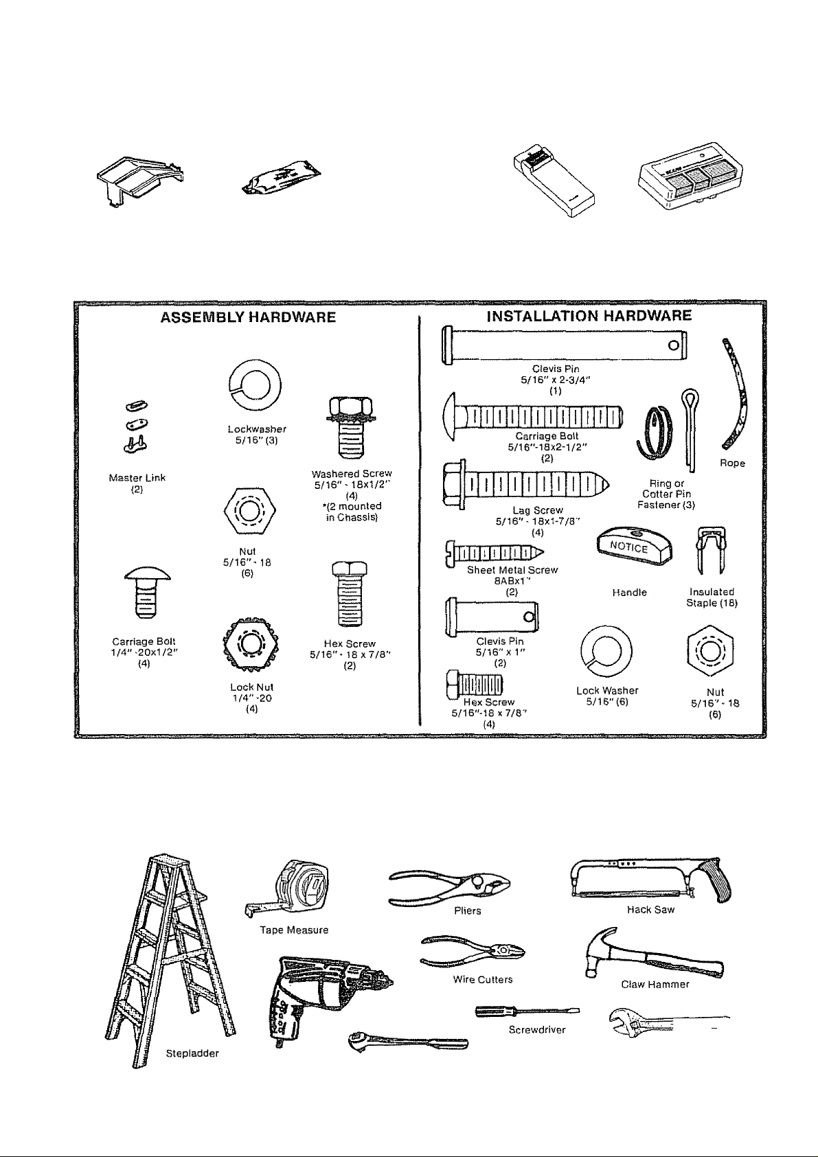
CARTON CHECK LIST
SEARS has packaged yourGarage Door Opener in two cartons which contain ali the partsand hardware
illustrated below and on Page 22.
Transmitters (2)
Sprocket
Cover
Rail
Grease
light Lena j1)
Touch Code Lock(1)
Model 13953610 ONLY
Model 139,53413
(1 ONLY)
SEPARATE ALL HARDWARE FOR ASSEMBLY AND INSTALLATION PROCEDURES AS SHOWN BELOW.
YOU’LL NEED TOOLS
During assembly and installation of your opener, the instructions will call for use of various hand toots. Have a
stepiadder handy, and those tools illustrated below: hammer, electric driil {& 3/16" and 5/16" drill bits), screw
driver, adjustabie end wrench or socket wrench kit, wire cutters, tape measure, pliers and hack saw,
'jOy
Electric Drill
Socket Wrench
Adiustable End Wrench
Page 4
start By Reading These Important Safety Rules
THIS SAFETY ALERT SYMBOL MEANS CAUTION - PERSONAL SAFETY OR PROPERTY
DAMAGE INSTRUCTION. READ THESE INSTRUCTIONS CAREFULLY.
THIS GARAGE DOOR OPENER IS DESIGNED AND TESTED TO OFFER REASONABLY
SAFE SERVICE PROVIDED IT IS INSTALLED AND OPERATED IN STRICT ACCORDANCE
WITH THE FOLLOWING SAFETY INSTRUCTIONS.
FAILURE TO COMPLY WITH THE FOLLOWING INSTRUCTIONS MAY RESULT IN SERIOUS
PERSONAL INJURY OR PROPERTY DAMAGE.
CAUTION: IF YOUR GARAGE HAS NO SERVICE ENTRANCE DOOR, INSTALL MODEL 53702 EMERGENCY RELEASE
KEYLOCK (PAGE 2). THIS ACCESSORY ALLOWS MANUAL OPERATION OF GARAGE DOOR FROM OUTSIDE IN CASE OF
POWER FAILURE.
KEEP GARAGE DOOR BALANCED. Sticking or
binding doors must be repaired. Garage doors,
doorsprings, cables, pulleys, brackets and their
hardware may be under extreme tension and can
cause serious personal injury. DO NOT ATTEMPT
ADJUSTMENTS. Call a garage door serviceman
to move or adjust door springs or hardware.
DO NOT WEAR RINGS, WATCHES OR LOOSE
CLOTHING while installing orservicing a garage
door opener.
To avoid serious personal injury from entangle
ment, REMOVE ALL ROPES CONNECTED TO
THE GARAGE DOOR before installing the garage
door opener.
DISENGAGE ALL EXISTING GARAGE DOOR
LOCKS to avoid damage to garage door,
installation and wiring must be in compliance
with your local building and electrical codes,
CONNECT POWER CORDONLYTOAPROPERLY
GROUNDED OUTLET.
DO NOT USE FORCE ADJUSTMENTS TO COM
PENSATE FOR A BINDING OR STICKING
GARAGE DOOR. Excessive force will Interfere
with the proper operation of the safety reverse
system or damage the garage door. (Page 17).
Fasten the CAUTION LABEL on the wall nearthe
lighted wall control asa reminderof safe operating
procedures.
tnstailwallcontroljoradditionalpush buttons) IN
A LOCATION WHERE GARAGE DOOR IS VISIBLE,
BUT OUT OF THE REACH OF CHILDREN. DO
NOTALLOWCHILDRENTOOPERATETHEWALL
PUSH BUTTON(S) OR TRANSMITTER. Serious
personal injury from a closing garage door may
result from misuse of opener.
CAUTION: Aclivateopeneronty when the door is in
f u II view, free of obstruction and opener is properly
adjusted. NO ONE SHOULD ENTER OR LEAVE
THE GARAGE WHILE DOOR IS IN MOTION. DO
NOT ALLOW CHILDREN TO PLAY NEAR DOOR,
LIGHTWEIGHT FIBERGLASS, ALUMINUM AND
STEEL DOORS MUST BE SUBSTANTIALLY RE
INFORCED TO AVOID DOOR DAMAGE. (See
page 15.) The best solution is to check with your
garage door manufacturer for an opener installa
tion reinforcement kit.
THE SAFETY REVERSE SYSTEM TEST IS IM
PORTANT. (See Pg. 18). Your garage door MUST
reverse on contact with a one-inch obstacle placed
on the floor. Failure to properly adjust the opener
may result in serious personal injury from a closing
garage door. REPEAT TEST AT LEAST ONCE
EVERY THREE MONTHS AND MAKE NEEDED
ADJUSTMENTS.
Use emergency release ONLY to disengage trolley
and, if possible, ON LY when the door is closed.
DO NOT USE RED EMERGENCY RELEASE ROPE
AND HANDLE TO PULL DOOR OPEN OR CLOSED
DISCONNECT ELECTRIC POWER TO GARAGE
DOOR OPENER BEFORE MAKING REPAIRSOR
REMOVING COVERS.
Page 5

Operation of Your Opener
CAUTION
ffl BEFORE YOU PROCEED, PLEASE READ THE SAFETY
RULES ON PAGE 4 AND OPERATING INSTRUCTIONS
ON THIS PAGE CAREFULLY.
® TO AVOID DIFFICULTY DURING INSTALLATION, DO
NOT RUN OPENER UNTIL INSTRUCTED TO DO SO
USING THE OPENER
Your opener can be activated by any of the following devices
(wait one-second between commands);
1 The transmitter. (The TOP (large) push button has been
factory preset to operate door) Hold push button down
until door starts to move
2 The lighted wali control., Hold button down until door
starts to move,
3 The Key Switch orTouch Code Lock(if you have installed
either of these accessories)
OPENING THE DOOR MANUALLY
The door can be operated manuaily by disconnecting it from
the opener THE DOOR SHOULD BE FULLY CLOSED IF
POSSIBLE. WEAK OR BROKEN SPRINGS COULD ALLOW
AN OPEN DOOR TO FALL RAPIDLY. PROPERTY DAMAGE
OR SERIOUS PERSONAL INJURY COULD RESULT.
Simply pull down sharply on red emergency release handle
and lift the door manually. To automatically reconnect the
door to the opener, press the wall control push button
DO NOT USE THE EMERGENCY HANDLE TO PULL THE
DOOR OPEN OR CLOSED
0 DO NOT PERMIT CHILDREN TO PLAY IN DOOR AREA.
o OPERATE ONLY WHEN THE OPENER IS PROPERLY AD
JUSTED AND DOOR IS VISIBLE AND UNOBSTRUCTED.
WHEN OPENER IS ACTIVATED;
1 If open, door will close. If closed, door will open
2 If closing, the door will reverse,
3 If opening, the doorwill stop (allowing space for entry and
exit of pets and for fresh air).
4 if the door has been stopped in a partially open position, it
will close
5. If an obstruction is encountered while closing, the door
will reverse.
6. If an obstruction is encountered while opening, the door
will stop.
7 If the optional Infrared Reversing Sensor is installed, the
garage door will reverse In the closing cycle when the
invisible beam is broken An open doorwill not ciose when
the beam is broken. The sensor has no effect in the open
ing cycfe.
THE OPENER LIGHT will turn on under the following con
ditions: when the opener is initially plugged in; when power Is
interrupted; when the opener is activated. It will turn off auto
matically after 4-1/2 minutes Bulb size-75 Watts maximum,.
CARE OF THE OPENER
When properly installed, the opener will provide high perfor
mance with a minimum of maintenance. Opener does not
require additional lubrication.
Most complaints of unsatisfactory opener operation can be
traced to problems with the door itself....OPENER iS NOT
iNTENDEDTOCORRECTPROBLEMSTHATARECAUSED
BY AN UNSAUNCEDOR BINDING DOOR, BROKEN DOOR
SPRINGS OR BY FAULTY DOOR HARDWARE.
When operated manually, a property balanced door will stay
in any point of travel while being supported entirely by its
springs.
LIMIT AND FORCE ADJUSTMENTS: These adjustments
must be checked and properly set when opener is installed.
Only a screwdriver is required. Weather conditions may
cause minor changes in door operation requiring some
re-adjustments, particularly during the first year of opera
tion. Page 17 refers to limit and force adjustments Follow
instructions carefully and repeat SAFETY REVERSE TEST
after any adjustment.
THE SAFETY REVERSE SYSTEM IS IMPORTANT (SEE
PG.18}.. GARAGE DOOR /MUSTREVERSE ON CONTACT
WITH A ONE-INCH OBSTACLE PUVCED ON THE FLOOR.
FAILURETOPROPERLYADJUSTOPENERMAYRESULT
IN SERIOUS PERSONAL IN JURY FROM ACLOSING GAR
AGE DOOR.
CHAIN TENSION ADJUSTMENT: After installation of the
opener and adjustment of forces and limits, chain may appear
loose. This is normal.
TO CHECK THE CHAIN TENSION: disconnect the trolley
by pulling the red emergency handle. If the chain returns to
the position described and iiluslrated in Step 5. Page 9, DO
NOT make ANY further adjustments.
THE TRANSMITTER: The 3-channel transmitter will operate
more than one garage door opener, if desired. The additional
push buttons may also be used to operate other remote con
trol devices, Transmitter(s) may be secured to a car sun visor
with clip(s) provided. Additional transmitters can be purchased
at any time. (Refer to Accessories, Pg, 2),
Any new transmitters must be set to the same code as orlgina!
transmitter and receiver. Page 19 explains how to change
your existing code and how to use the transmitter(s) with
other remote control devices. Self service of your radio con
trols is not recommended. If service is needed, contact your
nearest Sears Service Center.
TRANSMITTER BATTERY; The 9-Volt battery should pro
duce power for approximately one year. As long as there Is
adequate power, the transmitter battery test light will glow
when a push button is pressed (and the opener will operate).
When the light does not come on, replace battery If transmis
sion range lessens, check battery tight.
Avoid the inconvenience of unexpected failure by replacing
battery annually, preferably before winter. Use a genera!
purpose, 9 volt battery,
TO CHANGE BATTE RY: Remove visor clip and connecting
screw in transmitter case Set aside top of case and discard
old battery Snap connector onto new battery Replace top of
case and connecting screw. Replace visor clip.
MAINTENANCE OF YOUR OPENER
AT LEAST4 TIMES A YEAR
MANUALLY OPERATE DOOR. If it is unbalanced or bind
ing, call for professional garage door service
CHECK TO MAKE SURE DOOR OPENS AND CLOSES
FULLY. Adjust Limits and/or Force if necessary
REPEAT SAFETY REVERSE TEST. Make any necessary
adjustments (see page 18)
TWICE A YEAR
CHECK CHAIN TENSION. Adjust If necessary
ONCEA YEAR
OIL DOOR ROLLERS, BEARINGS AND HINGES,
REPLACE THE TRANSMITTER BATTERY, preferably be
fore winter.
Page 6
Assembly
TO AVOID INSTALLATION DIFFICULTIES, DO NOT RUN THE GARAGE DOOR OPENER UNTIL YOU ARE
INSTRUCTED TO DO SO.
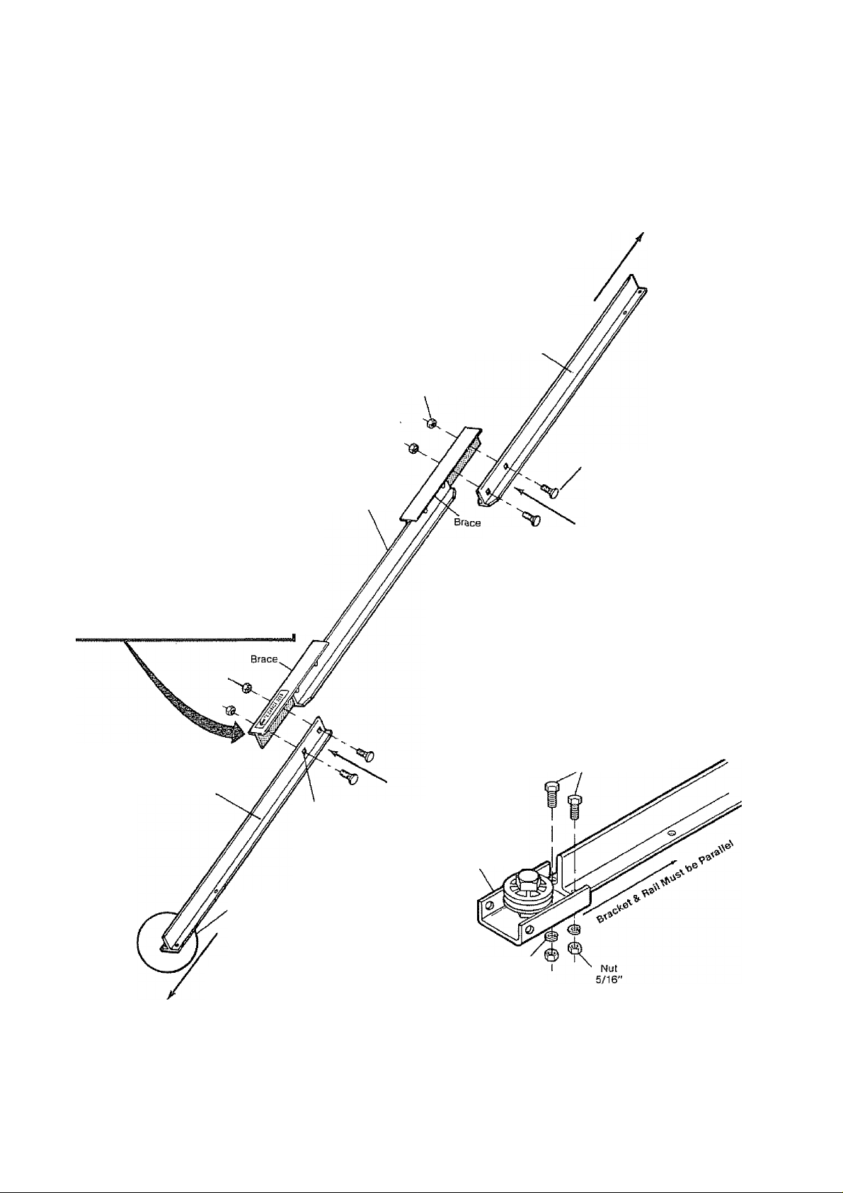
1 Assemble Tee Rail & Attach Cable Pulley Bracket
TEE RAIL BACK
{TO CHASSIS)
CAUTION: Do not tighten the lock nuts until bolt
necks are seated in square holes.
Tee Rail
(End Section)
1/4'LockHu!
Carriage Bolt
1/4"-20x1/2"
Tee Rail
(Center Section)
The center rail section MUST be
positioned on the LEFT SIDE of end
rails as shown.
Otherwise, trolley will hit against nut
when installed (Pg. 7).
Tee Rail
(End Sectiorr)
Cable pulley bracket
attaches to FRONT
END of Tee Rail
Square Carriage
Bolt Hole
PROCEDURE: Place the 3 Tee rail sections on a flat
surface for assembiy. THIS IS IMPORTANT, The end
sections are identical. THE CENTER SECTION MUST BE
POSITIONED WITH THE BRACES ON THE LEFTSIDE OF
END SECTIONS. If there is a label attached to the cen
ter section, make sure that the "directional arrow” is
pointing toward the front {to door).. Otherwise, study
the illustration CAREFULLY
(When assembled, Tee rail has a front-to-back posi
tion as shown).
Bolt rail sections together with the hardware illus
trated and from the direction indicated
SQUARE NECKS ON CARRIAGE BOLTS MUST BE
SEATED IN SQUARE HOLES IN RAIL SECTIONS,
Screws
, 5/16''-iax7/B "
Cable Pulley
Bracke!
TEE RAIL FRONT
(TO DOOR)
Lock Washer
5/16"
Position cable pulley bracket on front end of tee rail as
shown. Fasten securely with the hardware provided.
IMPORTANT: When tightening screws, besureto
keep bracket parallel to rail. Otherwise, rail may
bow when opener is operated.
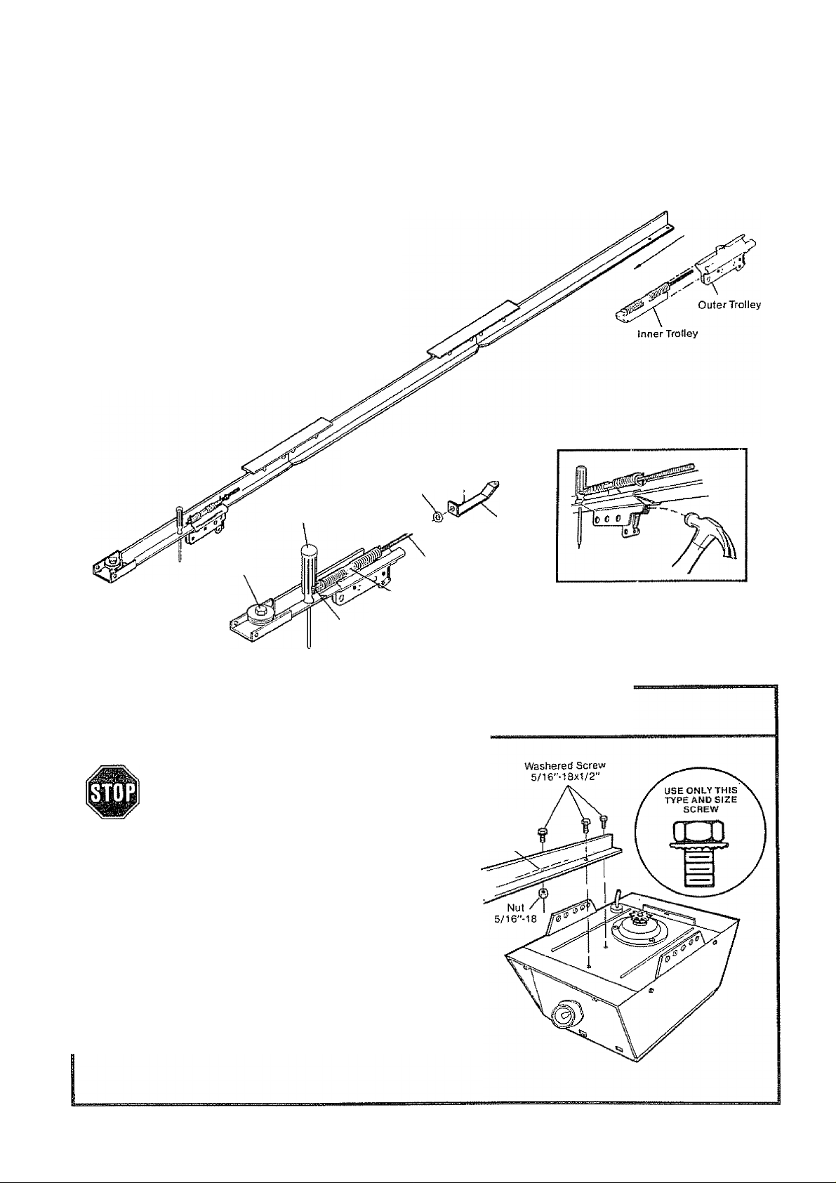
Page 7
Assembly
STEP 2 Install Trolley & Attach Chain Retainer Bracket
As a temporary stop, insert a screwdriver into
hole in front end of Tee rail as shown. Slide the
inner trolley onto the Tee rail until it is firmly against
the screwdriver,
NOTE: IftrolleyhitsagainstnutonTeerail,center
section was attached from wrong side and must
be repositioned. Review Step 1.
Slide the outer trolley onto theTee rail until it partially
engages the inner trolley and stops
TO FULLY ENGAGE TROLLEY: With a hammer,
firmly tap the back end of outer trolley just below the
rail guide, Outer trolley must move forward to fully
engage Inner trolley. Be careful to avoid damaging
trolley spring.
Temporary Stop Inner
Screwdriver f^dt
Cable
Pulley
Bracket
Flat End
Lock Washer _
5/16" ''
b/16" ®
Threaded
End
Trolley
Shaft
Attach inner nut, lock washer, chain retai ner bracket
and outer nut to trolley shaft in the order shown. DO
NOT TIGHTEN NUTS UNTIL STEP 5, PAGE 9.
Outer
,,^5/16''
Chain
Retainer
Bracket
Nut
STEPS Attach Tee Rail to Opener Chassis
USE ONLYTHOSE SCREWS MOUNTED
INTOPOFOPENERCHASSIS. FAILURE
TO DO SO WILL CAUSE SERIOUS DAM
AGE TO THE DOOR OPENER.
PROCEDURE; Place opener chassis on packing
ma terial to protect cover For convenience, place a
support under the cable pulley bracket.
Remove 5/16"-18x1/2" washered screws mounted
in top of opener chassis. Align holes in back end of
Tee rail with holes in opener chassis. Fasten the rail
to the chassis with washered screws previously
removed. CAUTION: USEONLYTHESESCREWS!
Use of any other screws will cause serious dam
age to door opener. Tighten screws securely,
insert a 5/16"-18x1/2" washered screw into trolley
stop hole in the Tee rail as shown. Tighten securely
with a 5/16" nut,
stop Hole
Tec Rail
(Back Section)
Trolley
Page 8

Assembly
STEP 4 Instan Chain and Cable
DO NOT REMOVE CHA IN A ND CABLE FROM CARTON
Detach cable from side of carton and fasten to trolley
with a master link from coin envelope.
MASTER LINK PROCEDURE: Push pins of master
link bar through loop of cable and hole in flat end of
trolley shaft (A) Push cap over pins and onto notches.
Slide dip-on spring over cap and onto pin notches
until both pins are locked in place.
Caution: Keep chain taut while installing to help
prevent kinking.
With trolley against the screwdriver, dispense cable
around pulley Proceed back around opener sprocket
fB) - be sure sprocket teeth engage chain-and fonward
to chain retainer bracket (C).
o
Opener Chassis /
Sprocket ^
install Chain and Cable
in This Direction
Use second master link to connect chain to retainer
bracket Check to make sure chain is not twisted.
Install Chain and Cable
in This Direction Trolley
As a permanent trolley stop, insert 5/16" washered
screw and nut into remaining hole in Tee rail front.
Tighten securely REMOVE SCREWDRIVER.
Master
Link
Outside
Bar
o
y Ì
O ......... qJ
Chain
^ Screw and Nut
Sprocket
Cover
Mounting
Plate
Remove
Screwdriver
Attach sprocket cover to chassis as shown. Insert
back tab in chassis slot Then bend cover forward and
insert front tab in slot provided on mounting plate
Page 9

STE P 5 Tighten the Chain and Cable
Tighten
Outer
Nut
CAUTION: Keep the chain from twisting as nuts
are turned.
PROCEDURE: Thread the outer nut toward trolley as
shown (Loosen inner nut first, if necessary).
Tension is correct when the chain is approximately
o o
Troltey
o ^
1^3
Lock
Washer
Chain
1/2" above base of Tee rail midway between cable
pulley bracket and chassis.
To maintain proper tension, turn inner nut toward chain
retainer bracket until tight
Sprocket noise can result if chain is either too
1/S Inch
Base of Tee Rail
loose or too tight.
CAUTION: Do not overtighten chain and cable.
Refer to Pages.
ASSEMBLY OF YOUR GARAGE DOOR OPENER IS NOW COMPLETE.
BEFORE YOU PROCEED WITH THE INSTALLATION OF YOUR GARAGE DOOR OPENER BE SURE TO
COMPLY WITH THE FOLLOWING SAFETY RULES:
KEEP GARAGE DOOR BALANCED. STICKING OR BINDING DOORS MUST BE REPAIRED. THE
GARAGE DOOR, THE DOOR SPRINGS, CABLES, PULLEYS, BRACKETS ANDTHEIR HARDWARE
MAY BE UNDER EXTREME TENSION AND CAN CAUSE SERIOUS PERSONAL INJURY. DO NOT
ATTEMPT ADJUSTMENTS. CALLAGARAGE DOOR SERVICEMAN TO MOVE, LOOSEN OR ADJUST
DOOR SPRINGS OR HARDWARE.
DO NOT WEAR WATCHES, RINGS OR LOOSE CLOTHING WHILE INSTALLING OR SERVICING A
DOOR OPENER.
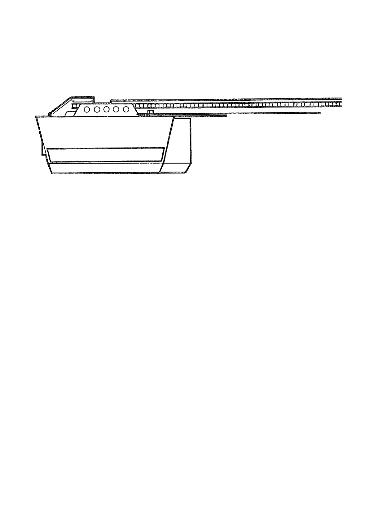
AS YOU PROCEED WITH THE REMAINING INSTRUCTIONS IN THIS OWNERS MANUAL, YOU MAY FIND IT
HELPFUL TO REFER TO THE FOLLOWING ILLUSTRATION OF THE FULLY ASSEMBLED AND INSTALLED
GARAGE DOOR OPENER.
IT IS RECOMMENDED THAT THE OPENER BE INSTALLED 7 FEET OR MORE ABOVE THE FLOOR
WHERE SPACE PERMITS.
CERTAIN INSTALLATION PROCEDURES VARY ACCORDING TO GARAGE DOOR TYPES. WHERE THE
DIFFERENCES OCCUR, BE SURE TO FOLLOW ONLY THOSE INSTRUCTIONS WHICH APPLY TO YOUR
DOOR CONSTRUCTION.
9
Page 10

Installation
STE P 1 Position & Instali Header Bracket
Installation procedures vary according to garagedoortypes. Follow only those instructions which apply to
your door as illustrated below.,
THE HEADER BRACKET IWUST BE RIGIDLY FASTENEDTO THE HEADER WALL OR CEILING.
REINFORCE WALL OR CEILING WITH 2x4 IF NECESSARY.
1. With door dosed, locate and mark the vertical
centerline of garage door. Extend line onto header
wall above door
2. Locate height for header bracket by opening door
to highest point of travel as shown. Draw an inter
secting horizontal iine on header wall 2" above
high point. This height provides travel clearance
for top edge of door.
NOTE: When headroom is notsufficientfor2"
clearance, the bottom edge of bracket may be
placed parallel to the high point of travel, or
bracket may be attached to ceiling.
Door Clearance Brackets are designed for low
headroom installations(Page 2). They replace
top brackets and rollers on the garage door,
thereby lowering the high point of doortravel.
Installation instructions are contained in the
accessory carton.
'■ Lag Screws
5/16"-18x1-7/8 ■
INSTALLATION
SECTIONAL DOOR AND
1-PIECE DOOR WITH TRACK
SECTIONAL DOOR
CURVED TRACK
tn N Header
? Bracket
Highest Point
of Travel
Door
Ceiling
Track
ONE-PIECE DOOR
HORIZONTAL TRACK
•JAMB HARDWARE
Header
Brackel
HighesI Point
of Travel
Position bracket as shown {bottom edge of the
bracket on horizontal line). Mark either top and
bottom or left and right bracket holes Drill 3/16"
pilot holes and fasten bracket
INSTALLATION
1 -PIECE DOOR WITHOUT TRACK
ONE PIECE DOOR
NO TRACK
PIVOT HARDWARE
ONE-PIECE DOOR
JAMB HARDWARE
NO TRACK
Header
Brackel
HighesI Point
of Travel
1 Follow instructions as described in 1 above
2 Locate height for header bracket by opening door
to highest point of travel as shown.. Measure the
distance from top of door to floor. Subtract actual
height of door Add 8" to the remainder. Refer to
example below
NOTE: If the total number of inches exceeds
the height available in your garage, use the
maximum height possible, On finished ceilings,
do not position the bracket closer than 1/2"
from ceiling.
Measuring from top of door, draw an intersecting
horizontal line on header wall at determined height.
Position bottom edge of header bracket on the
horizontal line, centering bracket on vertical line.
Mark either top and bottom or left and right holes.
Drill 3/16" pilot holes and fasten the bracket with
5/16" X T7/8" lag screws as shown above.
EXAMPLE
Distance from top of door (at
highest point of travel) to floor 92"
Actual height of door —68"
Remainder 4"
Add + 8"
Bracket height on header wall
:12"
{Measure UP from top of door
in closed position.)
10
Page 11

Installation
STEP 2
STEPS
Follow instructions which apply to your door type as illustrated below
TO PREVENT DAMAGE TO ALL LIGHTWEIGHT DOORS AND DOORS WITH WINDOWS, DO
NOT REST THE OPENER ON THE DOOR.
Attach Tee Rail to Header Bracket
PROCEDURE: Position opener chassis on garage
floor below header bracket. Use packing material
base to protect cover NOTE: To enable Tee rail to
clear sectional door springs, it may be necessary
to lift the chassis onto a temporary support
CAUTION: Chassis must either be secured to the
support or held firmly in place by another person.
Raise Tee rail until cable pulley and header brackets
come together. Align bracket holes and join with
clevis pin as shown. Secure with a ring or colter pin
fastener (if cotter pin is used, spread to secure)
Position Opener Chassis
SECTIONAL and ONE-PIECE
DOOR WITH TRACK
INSTALLATION
NOTE: A 2x4 is convenient for setting an ideal
door-to-Tee rail distance. It is not necessary where
headroom is insufficient.
PROCEDURE: Raise the opener chassis onto a stepladder Open garage door Place a 2x4 on edge on
top section of door near centerline. Rest Tee rail
on 2x4
ONE-PIECE DOOR
WITH NO - TRACK
INSTALLATION
PROCEDURE: Measure the distance from floor to
top of door (in fully open position and parallel to the
floor)
Using a slepladder as a support, raise the opener
chassis to the same distance from the floor (chassis
will have a slight angle as shown)
The top of the door should be level with the top of the
opener For maximum efficiency, do not position the
opener chassis more than 2 inches above this point.
Top o( Opener
11
Page 12

Installation
STEP 4
Hang Opener Chassis
THE OPENER CHASSIS MUST BE SECURELY FASTENED TO A ST/?yCTi/ffi4L SUPPORTOF GARAGE.
Three representative installations are shown„ Yours may be different. Hanging brackets should be angled
(Fig. 1) or crossed (Fig. 2) to provide rigid support. On finished ceilings (Fig. 3). attach a sturdy metal bracket
(not supplied) to ceiling joists before installing opener.
PROCEDURE: On EACH side of opener measure the
FIGURE 2
distance from chassis to structural support..
Cut both pieces of the hanging bracket to required
lengths. Flatten one end of each bracket and bend or
twist to fit fastening angles.
Do not bend at bracket
holes. Drill 3/16" pilot holes in structural support
Attach flattened ends of brackets to the support with
5/16"x1-7/8" lag screws,,
Lift opener and fasten to hanging bracket as shown
Checkto make sure Tee rati is centered over door.
5/16 "-18x7/6" Screw,
5/16" Lock Washer,
S/16"-18 Nut
REMOVE 2x4. Operate door manually. If door hits
the rail, raise header bracket.
Grease top and underside of rail surface on which
trolley slides. A tube of grease is supplied.
FIGURE 1
FIGURE 3
STE P S Attach Emergency Release Rope & Handle
USE EMERGENCY RELEASE ONLY TO
DISENGAGE TROLLEY. DO NOT USE
ROPE AND HANDLE TO PULL DOOR
OPEN OR CLOSED.
PROCEDURE: Thread one end of rope through hole
in top of red handle so'NOTICE' reads right side up as
shown Secure with an overhand knot NOTE: Knot
should be at least 1 inch from end of rope to pre
vent slipping. Thread other end of rope through hole
in release arm of outer trolley Adjust rope length so
that handie is 6 feet above the floor. Secure with an
overhand knot as above.
NOTE: If it is necessary to cut rope, heat seal cut
end with a match or lighter to prevent fraying and/
or raveling.
Bracket
(Not Supplied)
Overhand
Knot
FINISHED CEILING
Lag Screws
5/16"x1-7/8"
(Not Suppited)
5/16''-18x7/0" Screw
5/16" Lock Washer
5/16"-18 Nut
Emergency
Release Handle
Overhand
Knot
12
Page 13

installation
STEP 6
Instan Wall Control
LOCATE WALL PUSH BUTTON (OR ANY ADDITIONAL PUSH BUTTONS} WHERE GARAGE
DOOR IS VISIBLE, AWAY FROM DOOR AND DOOR HARDWARE AND OUT OF THE REACH
OF CHILDREN.
SERIOUS PERSONAL INJURY FROM A MOVING GARAGE DOOR MAY RESULT FROM MIS
USE OF THE OPENER. DO NOT ALLOW CHILDREN TO OPERATE WALL PUSH BUTTON(S)
OR THE TRANSMITTER.
FASTEN THE CAUTION LABELON THE WALL NEAR WALL PUSH BUTTON AS A REMINDER
OF SAFE OPERATING PROCEDURES.
PROCEDURE: Remove about a 1/4" of insulation
from each end of the 2-strand bell wire Connect one
end to the screw terminals on the back of wall control
as shown.
Fasten the wall control to an inside garage wall with
the 8ABx1" sheet metal screws provided A con
venient place is beside the service door and OUT OF
THE REACH OF CHILDREN..
Run the bell wire up the wall and across the ceiling to
garage door opener. Use insulated staples to secure
wire,
The receiver terminals and the antenna are located
on the back panel of the opener chassis. Position
antenna wire as shown. Then connect wire by color
to the white and red opener terminal screws.,
Installation
Flange
Bottom
Installation
Fiange
Top
Walt Control
Push Button
OPERATION OF THE LIGHTED WALL CONTROL
Press and release to open or close door
Press and release again to REVERSE door during CLOSING cycle or
to STOP door during OPENING cycle
NOTE: Wait about 1-second between commands.
13
Back Panel
of Opener
WIRING INSTRUCTIONS FOR ACCESSORIES
Open Door Indicator:
To white & orange opener terminais
Outdoor Key Switch:
To red & white opener terminais
Touch Code Lock:
To red and white opener terminals
infrared Reversing System;
To while & black opener terminals
Antenna
Page 14

Installation
STEP?
PROCEDURE: Install a light bulb.-(75 Watts Max
imum) in socket as shown The light will turn on and
remain lit for 4-1/2 minutes when power is connected.
After 4-1/2 minutes it will turn off..
If light bulb burns out prematurely due to vibra
tion, replace with a “rough service” bulb.
INSTALLING LENS:
Slide lens into the lens guides as shown. Snap bottom
tabs into lens slots
Install Light and Lens
STEPS Connect Electric Power
TO AVOID SERIOUS PERSONAL INJURY FROM ENTANGLEMENT, REMOVE ALL ROPES
CONNECTED TO THE GARAGE DOOR BEFORE OPERATING OPENER.
TO AVOID DAMAGE TO GARAGE DOOR AND OPENER, MAKE DOOR LOCKS INOPERATIVE
BEFORE CONNECTING ELECTRIC POWER. USE A WOOD SCREW OR NAIL TO HOLD THE
LOCKS IN “OPEN” (UNLOCKED) POSITION,
INSTALLATION AND WIRING MUST BE IN COMPLIANCE WITH LOCAL ELECTRICAL AND
BUILDING CODES,
OPERATION AT OTHER THAN 120V 60Hz WILL CAUSE OPENER MALFUNCTION AND DAMAGE.
Light Lens
Opener MUSTbe permanently wired or plugged into
a grounded 3-prong receptacle wired according to
local electrical codes DO NOT use a 2-wire adapter.
DO NOT use an extension cord PERMANENT WIRING
CONNECTION
Ground Tab
Ground Screw
RIGHT WRONG
IF LOCAL CODES REQUIRE PERMANENT WIRING:
DISCONNECT POWER AT FUSE BOX
BEFORE PROCEEDING..
PROCEDURE: Refer to illustration. Make connec
tion through the 7/8 inch diameter hole in top of
opener chassis
1. Remove opener chassis cover by removing the
cover screws
2 Remove attached 3-prong cord
3 Connect the black (line) wire to the black wire on
terminal block; white (neutral) wire to the white
terminal wire; the green (ground) wire to green
ground screw.
CAUTION: BE SURE THAT UNIT IS GROUNDED
ACCORDING TO LOCAL CODE.
IMPORTANT NOTE: TO AVOID INSTALLATION
DIFFICULTIES, DO NOT RUN OPENER NOW.
White Wire
14
Page 15

Installation
Follow instructions which apply to your door type as illustrated below
STEP 9 Install Door Bracket and Plate
TO PREVENT DAiWiAGE TO LIGHTWEIGHT GARAGE DOORS, ALWAYS REIN FORCETHE INSIDE
OF DOOR—BOTH VERTICALLY AND HORIZONTALLY-WITH 2x4 BOARDS OR ANGLE IRON.
Horizontal brace should be at least 6 feet long, Vertical brace should cover height of top panel. The best solution
is to check with your garage door manufacturer for a door reinforcement kit for an opener installation.
Sectionaf Door Installation Procedure
1 Assemble the door bracket and plate as shown.
SECTIONAL DOOR
-II
—^ 1
Vertical 1
Center
Line 1
___
(
1
}
1
Header
„Bracket
1
Header
Wall
j
!
Door Bracke! &
/PlaSe Assy
Topoi Door
Center bracket on previously marked vertical
guideline.
Position bracket assembly on face of door within
the following limits; A. Top edge of bracket 2" to
4" below the top edge of door. B. Directly below
any structural support across top of door.
Placement depends on your particular needs.
Mark and drill 5/16" TOP and BOTTOM fasten
ing holes Secure bracket as shown,
Carriage Boli —
5/16'-18x2-VS"
Door Bracket
Plate
Door
Arm
Reinforcement
Board for
Lightweight Doors
All One“Piece Door Installation Procedure
NOTE: The door bracket has left and right side
fastening holes. Assemble and install the door
bracket and plate if your installation requires top
and bottom fastening holes.
1.. Center bracket (with or without plate as required)
on top edge of door as shown. Mark holes
2. Drill two 5/16" holes and fasten door bracket
with hardware supplied
NOTE: If the door has no exposed framing,
drill 3/16" pilot holes and use 5/16"x1-1/2"
lag screws (not supplied) to fasten bracket to
top of door.
Door Bracket
Plate
Lock Washer
5/16"
Inside Edge
of Door of
Reinforcement Board
Nut
5/16"-16
NOTE: Door bracket may be installed on face of
door if required for your installation. (Refer to
dotted linedrawing,) HOWEVER, drill3/16"pilot
holes and substitute 5/16"x1 '1/2"iagscrews(not
supplied) to fasten the bracket to door.
ONE PIECE DOOR
Optional ■
Face of Door
Installation
Door Bracket
Plate
(Optional)
Top Edge
of Door
(Outside)
(Optionall
Carriage Bolt
S/16'-18x2-1/2'
15
Vertical
Center ‘
Line
Page 16

Installation
STEP 10 Connect Door Arm to Trolley
Follow only those instructions which apply to your door type
SECTIONAL DOOR INSTALLATION ONLY
FIG. A. Make sure garage door Is closed tight. Connect
straight door arm section to trolley with a clevis pin. Secure
with a ring or cotter pin fastener{if colter pin is used, spread
to secure.)
Fasten curved sectior^ to door bracket in the same way
FIG.. B. Bring arm sections together. Find two pairs of holes
that line up and join sections
Insert screws from straight arm side Select holes as far
apart as possible to increase door arm rigidity
FIG. C, If holes do not line up as shown in FIG. B.., cross door
arms in scissor fashion.. When one set of holes lines up, insert
screw and 'finger tighten' with a lock washer and nut
Puli the emergency release rope to disengage trolley.
Bring arm sections together and Insert screw into second set
of holes Install lock washer and nut Tighten screws
Proceed to Step 1, Pg. 17, The trolley will re-engage
automatically when opener is operated.
ALL ONE-PIECE DOOR INSTALLATIONS
Door
ASSEMBLE DOOR ARM PROCEDURE: Connect straight
and curved door arm sections together to longest possible
length.. With door closed, connect straight door arm section
todoor bracket with a clevis pin Secure with a ring or cotter
pin fastener (if cotter pin is used, spread to secure)
Before connecting door arm to trolley, limits of travel must be adjusted on one-piece doors. Limit adjustment
screws are located on left side panel of opener as shown in illustration on Pg, 17. Follow procedures below
PROCEDURE- OPEN DOOR ADJUSTMENT
Decrease up limit Turn UPilmitadjustmentscrewcounter
clockwise 4 complete turns.
Press Wall Control button. Trolley will travel to full open
Manually raise door to open position (parallel to floor) and lift
door arm to troliey The arm should touch trolley just in back
of doorarm connector hole as shown in solid line drawing If
arm does not extend farenough, adjust limit further One full
turn equals 2 inches of door travel
CONNECT DOORARM TO TROLLEY; With door closed, join curved arm to connector hole in trolley with remaining clevis
pin. Secure with ring or cotter pin fastener NOTE: it may be necessary to lift door slightly to make connection.
Run opener throught a complete travel cycle If top of door has a slip'-, oownward' slant in full open position, decrease UP
limits until door is parallel to floor
Bracket
Clevis Pin
PROCEDURE - CLOSED DOOR ADJUSTMENT
Decrease down limit. Turn DOWN limit adjustment screw
clockwise 8 complete turns.
Press Wall Control button. Trolley will travel to full close
Manually close door and lift door arm to trolley Arm should
touch trolley just ahead of doorarm connector hole as shown
in dotted line drawing If arm is behind the connector hole,
adjust limit further. One full turn equals 2 incfies of door
travel
I#“ Cotter Pin
Screws
5/16"-18 X 7/8
Lock
Washers
Nuts
5/16'-18
16
Page 17

Adjustment
STE P 1 Adjust UP and DOWN Limits
LIMIT ADJUSTMENT settings regulate the points at which Limit
the door will stop when moving up or down
NOTE: Door STOPS in UP direction If anything inter
feres with door travel. The door REVERSES in DOWN
direction if anything interferes with door travel (includ
ing binding or unbalanced doors),
PROCEDURE: To operate opener, press Wall Control push
button or transmitter. Run opener through a COMPLETE
TRAVEL CYCLE. Limit adjustments are not necessary when
the door opens and closes completely and does not reverse
unintentionally in down direction.
The following chart outlines adjustment procedures. Run opener through a COMPLETE TRAVEL CYCLE AFTER
EACH ADJUSTMENT. NOTE: REPEATED OPERATION OF THE OPENER DURING ADJUSTMENT PROCEDURES
MAYCAUSETHEMOTORTOOVERHEATANDSHUTOFF.SIMPLYWAITISMiNUTESANDTRYAGAIN. Readihechart
carefully before proceeding to Step 2. Use a screwdriver to make limit adjustments
n —;//
V /
LIMIT ADJUSTMENT CHART
IF DOOR DOES NOT OPEN COMPLETELY
BUT OPENS AT LEAST FIVE FEET
Increase UP travel. Turn UP LIMIT adjustment screw clock
wise. One turn equals 2 inches of travel
If door doesn’t open at least 5 feet: adjust OPEN FORCE
as explained in Step 2
IF DOOR DOES NOT CLOSE COMPLETELY
(ON SECTIONAL DOORS)
Lengthen the door arm. (See Step 10, Page 16)..
If door arm is at maximum length, increase DOWN travel..
Turn down limit adjustment screw counter clockwise One
turn equals 2 inches of travel
If door still will not close completely, the header bracket is
positioned loo high. Repeat Step 1, Page 10
Increase DOWN travel. Turn down limit adjustment screw
counterclockwise One turn equals 2 inches of travel
IF DOOR REVERSES WHEN CLOSING AND THERE
Test door for binding; Pul! emergency release handle
Manually open and close door. If door Is binding, call a
door serviceman..
If door is not binding or unbalanced, adjust CLOSE FORCE..
See Step 2.
IF OPENER REVERSES IN FULLY CLOSED POSITION
Decrease DOWN travel Turn down limit adjustment screw
clockwise One turn equals 2 inches of travel.
___
» Adjustment
tNCnCASC THAVH LlUIT ADJUSryENT
.....
Left Side
Panel
IF DOOR DOES NOT CLOSE COMPLETELY
IS NO INTERFERENCE TO TRAVEL CYCLE
(ON ONE-PIECE DOORS)
Adjustment Label
LIMIT UPVt/UMn
STEP 2 Adjust Force
DO NOT USE FORCE ADJUSTMENTS TO COMPENSATE FOR A BINDING OR STICKING GARAGE DOOR.
EXCESSIVE FORCE WILL INTERFERE WITH PROPER OPERATION OF SAFETY REVERSE SYSTEM OR
DAMAGE GARAGE DOOR.
Force Adjustment Controls are located on rear panel of
opener FORCE ADJUSTMENT settings regulate amount
of power required to open and close door
NOTE; Door STOPS in UP direction if anything inter
feres with door travel. The door REVERSES in DOWN
direction if anything interferes with doortravel (includ
ing binding or unbalanced doors).
If force adjustments are set too light, door travel may be
interrupted by nuisance reversals in DOWN direction and
stops in UP direction. As weatherconditionscan affect door
movement, occasional adjustment may be needed.
The maximum force adjustment range is 260 degrees, about
3/4 of a complete turn, Do not force controis beyond that
point, Turn force adjustment controls with a screwdriver.
FORCE ADJUSTMENT CHART
TEST DOWN (CLOSE) FORCE
Grasp the door handle or door bottom when door is about
halfway through DOWN (C LOSE) TRAVEL The door should
reverse. If the door is hard to hold or doesn't reverse, de
crease the DOWN (CLOSE) FORCE by turning the control
in a counter clockwise direction Make 10 degree turn adjust
ments until the door reverses normally After each adjust
ment, run the opener through a complete travel cycle
Back Panel
of Opener
IF DOOR DOESN’T OPEN AT LEAST 5 FT
Increase UP (OPEN) FORCE by turning control clockwise.
Make 10 degree turn adjustments until the door opens
completely. Readjust UP LIMIT if necessary. After each
adjustment, run opener through a complete travel cycle
IF DOOR REVERSES DURING DOWN (CLOSE) CYCLE
Increase DOWN (CLOSE) FORCE by turning control clock
wise Make 10 degree turn adjustments until the door
completes close cycle. After each adjustment, run opener
through a complete travel cycle.
Force
Adjustment
^ Controls
Adjustment
Label
17
Page 18

Adjustment
3 Test Safety Reverse System
THE SAFETY REVERSE SYSTEM TEST IS IMPORTANT. THE GARAGE DOOR Mt/STREVERSE
ON CONTACT WITH A ONE INCH OBSTACLE PLACED ON THE FLOOR. FAILURE TO PRO
PERLY ADJUST OPENER MAY RESULT IN SERIOUS PERSONAL INJURY FROM A CLOSING
GARAGE DOOR. REPEAT TEST AT LEAST FOUR TIMES A YEAR AND ADJUST AS NEEDED.
PROCEDURE: Place a 1-inch obstacle on the floor under the garage door Operate door in DOWN direction
The door must reverse on the obstruction.
if a SECTIONAL door STOPS on the obstruction,
lengthen door arm until the door reverses in DOWN
direction, (Refer to Step 10, FIG, C., Page 16 Fasten
sections together to longest possible length).
If a ONE-PIECE door stops on obstruction, door is
not traveling far enough in DOWN direction. Increase
the DOWN limit by turning DOWN limit adjustment
screw counterclockwise 1/4 turn. REPEAT TEST.
When the door reverses on the 1-inch obstruction,
remove obstruction and run opener through a com
plete travel cycle. Door must not reverse in closed
position. If it does, repeat Adjustment Steps 2 and 3.
SECTIONAL DOOR
ONE-PIECE DOOR
1 Inch Obstruction
REPEAT ADJUSTMENT STEP 3 AFTER:
1. EACH ADJUSTMENT OF DOOR ARM LENGTH, CLOSE FORCE OR DOWN LIMIT.
2. ANY REPAIR OR ADJUSTMENT OF GARAGE DOOR (INCLUDING SPRINGS AND HARDWARE).
3. ANY REPAIR OR BUCKLING OF THE GARAGE FLOOR.
4 ANY REPAIR OR ADJUSTMENT OF THE GARAGE DOOR OPENER.
(Optional) STEP 4 Install Infrared Reversing System
The INFRARED REVERSING SENSOR provides an
ADDITIONAL measure of safety against a small child
being caught under a garage door It uses an invisible
beam which, when broken by an obstruction, causes a
closing door to open and prevents an open door from
closing.
After the garage door opener has been completely
installed and adjusted, the INFRARED REVERSING
SENSOR accessory can be installed. Instructions are
included with this optional device
1 inch Obstruction
_J
7
H// itjIU/I //// //f/ % t/f/ //// /if/ iff
18
Page 19

Radio Controls
Your 3-channel transmitter(s) will operate more than one garage door opener, if desired Also, refer to the catalog
packed with your opener for remote light products which can be operated by the additional push buttons on the
transmitter(s).
Instructions are given below for changing codes and/or using the transmitterfs) with additional receivers,
PLEASE KEEP THIS INSTRUCTION MANUAL HANDY FOR FUTURE REFERENCE.
SETTING/CHANGING YOUR CODE IN RECEIVER(S) AND TRANSfifilTTERiS)
DISCONNECT POWER TO OPENERfOR OTHER
DEVICES) BEFORE SETTING OR CHANGING
THE CODE IN THE RECEiVER(S).
TheTOP(Large) transmitter push button has been
factory preset to operate the garage door opener.
Each push button is programmed to operate by
sliding RECEIVER code switch #1 to a specific
position {+, - orO). Detailed instructions are given
below,
1, Decide which transmitter push button you want to
use to operate a receiver.
2. Remove screw on back of transmitter(s). Carefully
turn case over (push button side up).
3 Remove case top. CAUTION: Be careful not to
move circuit board components.
4. Locate the RECEIVER code switch block
TRANSMITTER
TOP (Large)
Push Button
m TO USE TOP (LARGE) TRANSMITTER BUTTON:
Set RECEIVER code switch 1 to minus (-).
© TO USE CENTER TRANSMITTER BUTTON: Set
RECEIVER code switch 1 to center (0}
© TO USE BOTTOM TRANSMITTER BUTTON: Set
RECEIVER code switch 1 to plus (+)..
TOSETTHECODE, use a pen or screwdriver. Begin
with code switch 2 on the RECEIVER. Slide one or
more of the switches to plus, minus or center(O),
Hold transmitterfs) alongside receiver code switch
Set code switches 2 through 9 in transmitter(s) to
match receiver switch positions.
NOTE: Code switches 2 through 9 on ALL the
receivers operated by the transmitter(s) must
MATCH switches 2 through 9 in transmitter(s).
CAUTION: If you press more than ONE push but
ton at the same time, transmitter will not operate.
+123456789
»laiiSiiBS
RECEIVER TRANSMITTER
19
Page 20

Having a Problem?
SITUATION
OPENER DOESN’T OPERATE
FROM EITHER WALL PUSH
BUTTON OR TRANSMITTER
OPENER OPERATES FROM
TRANSMITTER BUT NOT FROM
WALL PUSH BUTTON
DOOR OPERATES FROM
WALL PUSH BUTTON BUT NOT
FROM THE TRANSMITTER
PROBABLE CAUSE & SOLUTION
1. Have you disengaged ali door locks? Review Step 8, Page 14
2. Does the opener have electric power? Plug a lamp into the outlet If it
doesn't light, check fuse box or circuit breaker (Some outlets are con
trolled by a wall switch).
3. Repeated operation may have tripped the overload protector in the motor.
Wait 15 minutes. Try again.
4. Is there a build-up of ice or snow under door? Door may be frozen to
ground. Remove any obstruction
5. Remove belt wire from opener terminals. Touch red and white screw ter
minals together with a jumper wire, if opener runs, check for a faulty wire
connection at wall push button or a short under staples.
1. Is wall push button lit? If not, refer to No. 5 above and follow same
procedure.
2, Are wiring connections correct? Review Step 6, Pg.13.
1 Does the battery test light glow when transmitter push button is pressed?
If not, replace the battery (Page 5 tells you how.)
2. If you have two transmitters and only one operates, review code setting
procedures on Page 19. Receiver and ALL transmitters must be set to
same code,
3. Is transmitters) operating additional remote control devices? See code
setting procedures on Page 19
4. Did you press transmitter button designated to operate garage door
opener?
5. Re-program receiver(s) and ALL transmitters. Try setting ALL the code
switches in plus, center or minus positions, If transmitters) works, you
can try a random code switch setting again, if you desire.
TRANSMITTER HAS
SHORTRANGE
THE GARAGE DOOR OPENS
AND CLOSES BY ITSELF
DOOR DOESN’T OPEN
COMPLETELY
1. Check battery test light, if the light is out, change the battery(Page 5 tells
you how).
2. Change the location of transmitter in the car.
3 A metal garage door, foil-backed insulation or metal siding will reduce
transmission range.
4, Check to be sure the antenna on the back panel of the opener extends
fully downward.
1, is there a neighbor with a garage door opener using the same frequency
code? Change your code. Review Page 19.,
2, Check to make sure that the transmitter push button(s) is not stuck in the
‘down’ position.
3, Remove beli wire from opener terminals and operate from transmitter
only. If this solves the problem, the wall push button is faulty (replace), or
there is a short or broken wire between push button and opener.
1, Is something obstructing the door?
2, If door opens at least 5 feet, travel limits may need to be increased. One
turn equals 2 inches of travel. See Pg. 17. Repeat Safety Reverse Test
after adjustment Is complete.
3, If door has been working properly but now doesn’t open all the way,
increase UP FORCE. See Pg 17. Repeat Safety Reverse Test after adjust
ment is complete
DOOR DOESN’T CLOSE
COMPLETELY
1, Review the Travel Limits Adjustment Chart on Page 17. Repeat Safety
Reverse Test after any adjustment of door arm length, close force or
down limit.
20
Page 21

Having a Problem? (Continued)
SITUATION
DOOR WON’T CLOSE
DOOR REVERSES FOR
NO APPARENT REASON
OPENER LIGHT
PROBABLE CAUSE & SOLUTION
Th6 infrarsd Rsversing S6nsor(if you have installed this accessory) may
be misaligned or obstructed Disconnect sensor and check door opera
lion. If problem disappears, correct alignment.
Is something obstructing the door? Pull red emergency release handle.
Operate door manually. If it is unbalanced or binding, call a garage door
serviceman to correct the problem,
Clear any ice or snow from garage floor area where garage door closes.
2
Review the Force Adjustment Chart on Page 17. Repeat Safety Reverse
3
Test after adjustment is complete.
If door reverses in FULLY CLOSED position, decrease travel limits (See
Pg 17) and repeat Safety Reverse Test after adjustment is complete.
THE NEED FOR OCCASIONAL ADJUSTMENT OF FORCE AND LIMIT SET
TINGS IS NORMAL WEATHER CONDITIONS IN PARTICULAR CAN AFFECT
DOOR TRAVEL
The infrared Reversing Sensor(if you have installed this accessory) may
5.
be misaligned or obstructed. Disconnect sensor and check door opera
tion. If problem disappears, correct alignment.
DOESN’T TURN ON ^
1, Replace the light bulb (75\A/atts Maximum) Use rough service bulbs if
standard bulbs burn out prematurely due to vibration (Vibration may be
caused by loose end panels. Retighten screws).
DOESN’T TURN OFF
1, There may be a defective ground at celling or wall receptacle. Unit must
be grounded.
OPENER STRAINS OR
MAXIMUM FORCE IS NEEDED
TO OPERATE DOOR
OPENER MOTOR HUMS
BRIEFLY, THEN WON’T RUN
OPENER WON’T OPERATE
DUE TO POWER FAILURE
CHAIN DROOPS OR SAGS
1. Door may be out of balance. Use emergency release rope and handle to
disconnect trolley Open and dose door manualiy. ^
A properly balanced doorwill remain in any point of travel while being sup
ported entirely by its springs If it does not, cal! a garage door serviceman to
correct problem.
Trolley may be jammed into rai I stop bolts. Pull or push on door while motor
1.
is humming to release jammed condition. Re-adjust door limits (Page 17)
to prevent over-travel.
If problem occurs on the first operaiion during the installation process or
2.
after the chain was removed and re-instailed, the motor may be out of
phase. Remove chain; cycle motor to down position (Observe the drive
sprocket When it turns in clockwise direction and stops, motor is in down
position), Re-instail chain.
Use emergency release rope and handle to disconnect troiley, Door can
be opened and closed manually. When the power is restored, press the
wall push button and trolley will automatically reconnect
The emergency release key lock accessory (for use on garages with no
service door) disconnects the trolley from outside the garage In case of
power failure.
It is normal for the chain to droop slightly in closed door position. Use
emergency release rope and handle to disconnect troiley If chain returns
to normal height when trolley is disengaged and door reverses on a one-
inch obstruction, no adjustments are needed. See Page 9.
21
Page 22

Repair Parts
RAIL ASSEMBLY PARTS LIST
INSTALLATION PARTS LIST
KEY
NO.
11
12
PART
NO.
41D2736-1
1
10A13
2
41A3012
3
29C121-2
4
41A2828
5
219A323
6
41A2829
7
12B374
8
12B380
9
10
17BB35
173B34
12B350
NOT SHOWN
41A2815
114A976
DESCRIPTION
Wall control assy
9 volt battery
Transmitter case, cover and screw assy
Transmitter visor clip
Emergency rope and handle assy
2-Strand bell wire
Header bracket plus cotter pin and clevis
Door bracket
Door bracket plate
Curved door arm section
Straight door arm section
Hanging brackets
Installation hardware bag (includes hardware illus
trated on Pages)
Owners manual
KEY
PART
NO.
1 1A99S
2 41B2617
41B2771
3
12A197
4
2B313
5
183B93
6
41B2616
7
41G2735
8
41A2814 Rail assy, hardware kit (includes hardware
NO.
DESCRIPTION
Master link kit
Outer trolley
Inner trolley
Chain retainer bracket
Tee rail-center section
Tee rail-end section (each)
Cable pulley bracket assy.(each)
Chain and cable
NOT SHOWN
illustrated on Page 3)
-11
12 fh
22
Page 23

Repair Parts
Chassis Assembly Parts List
KEY
PART
NO..
NO.
31C290
1
41A2827
2
41 A2817
3
41B2991
4
41A3075
5
17SB88
6
7 108D30'1
a 308387
30B363
9 12A373
KEY
PART
NO.
DESCRIPTION
Sprocket cover
Gear and sprocket assy
Complete with:
Spring washer
Thrust washer
Retaining ring
Bearing plate
Roll pins (2)
Drive gear
Worm gear
Helical gear w/retainer
Grease
Drive/worm gear kit w/grease
Roll pins (2)
Line cord Complete with:
End panel
Light socket End panel w/al! labels
Lens
Capacitor- 1/3h p
Capacitor - 1/2h.p,
Capacitor bracket
NO.
10 41A3150
11 41A2821
41D2748-2
12
41D2748
41A2B18
13
41D3013
14
41C3005
15
41C2726
16
17 41A3027
18 41A2S26
19 41A2822
41A3066
20
41A3076
21
NOT SHOWN
41A282S
DESCRIPTION
Terminal block w/screws
Universal repiacement motor
Cover - Model 139.53413
& ModeM 39.53606
Cover - ModeM 39.53403
Helical gears retainer w/grease
Limit switch assembly
RPM sensor assembly
Wire harness assy., with plug
Motor bracket and bearing assy.
Shaft bearing kit
Interrupter cup assy.
Receiver logic board assy
Logic board
End panel w/all labels
Chassis assy hardware kit (includes screws
not designated by number in iliustratlon)
23
Page 24

SEARS/CRRFTSMflH.
Owners Manual
Garage
Door
Opener
Models:
139.53403
139.53413
139.53606
139.53610
MAINTENANCE AGREEMENTS ... YOUR WAY TO BUY TOMORROW’S SERVICE
ATTODAY’S PRICE... With nationwide service and the benefits of a Sears warranty plus a Sears Mainten
ance Agreement, you don’t have to worry about cosily repairs resulting from normal use.
The Maintenance Agreement does not cover installation or re-installation of the product or damage resulting from
external causes such as: acts of abuse, fire, flood, wind, lightning, freezing, etc.
To Purchase a Sears Maintenance Agreement - Ask Any Salesperson or Call Sears Service Today.
Now that you have purchased your Sears Garage Door Opener, should
you ever need repair parts or service, simply contact any Sears Service
Center and most Sears, Roebuck and Co stores Be sure to provide ail
pertinent facts when you call or visit,
The MODEL NUMBER of your garage door opener is printed on a label
located on the front panel of the opener chassis.
All parts listed may be ordered from any service center and most Sears
stores.
WHEN ORDERING REPAIR PARTS, ALWAYS GIVE THE FOLLOW
ING INFORMATION:
©part NUMBER ® PART DESCRIPTION
©MODEL NUMBER ©NAME OF ITEM
If the parts you need are not stocked locally, your order will be elec
tronically transmitted to a Sears Repair Parts Distribution Center for
handling.
IMPORTANT NOTE: If you suspect radio control malfunction, contact
your nearest SEARS Service Center
HOWTO ORDER REPAIR PARTS
■•■U OjiiiiiHiiiiiiiiiiÉiiiaiiu KJM
-JAW МЭС
--------
.......
— дад.
..................
SHXZZSSÜWiC
SEARS WARRANTY
FULL 90 DAY WARRANTY ON GARAGE DOOR OPENER
For 90 days from the date of purchase, Sears will repair this Garage Door Opener, free of charge, if defective in
materia! or workmanship.
From the 91st day until one year from the date of purchase, Sears wiil furnish replacement parts for any defective parts,
free of charge. You pay for labor,
LIMITED WARRANTY ON 1/2 HP AND 1/3 HP MOTORS FOR CRAFTSMAN OPENERS
1 /2hp Motor: After 1 year and through 5 years, if the motor on this Garage Door Opener is defective. Sears will furnish a
replacement motor, free of charge. You pay for labor.
1/3hp Motor: After 1 year and through 3 years, if the motor on this Garage Door Opener is defective, Sears will furnish a
replacement motor, free of charge. You pay for labor.
Sears will not be liable for loss or damage to property or any incidental or consequential loss or
expense from property damage due directly or indirectly from the use of this product.
Some states do not allow the exclusion or limitation of incidental or consequential damages, so the above limitation or
exclusion may not apply to you.
This warranty does not cover repairs necessary because of operatorabuse or negligence, including thefailure to install,
adjust and operate this garage door opener according to the instructions contained in the ownei^s manual.
WARRANTY SERVICE IS AVAILABLE BY SIMPLY CONTACTING THE NEAREST SEARS SERVICE CENTER/DEPART-
MENT IN THE UNITED STATES., This warranty applies only while the product Is in use in the United States.
This warranty gives you specific legal rights, and you may also have other rights which vary from state to state.
SEARS ROEBUCK AND CO., Dept. 698/731A Sears Tower, Chicago, IL 60684
Site
114A976B
IMiC
Г45С
UNITED WARRANTY
LIMITATION ON LIABILITY
■1^« сЧм
1987, Sears, Roebuck and Company
All Rights Reserved
СМНМ1Ш11ШВМ|П «Sm
Printed in Mexico
 Loading...