

Page 1
шла
OWNER’S
MANUAL
Model No.
139.53225SRT
139.53325SRT
139.53425SRT
139.53628SRT
139.53629SRT
CRAFTSMAN®
139.53635SRT
139.53637SRT
139.53824SRT
For Residential Use
Only
Caytion:
Read and follow all safety
ryles and ope-ratlng
instryctlons fciefore first
yse of this product
Fasten the manyat near
the garage door after
instaflation.
GARAGE DOOR OPENER
m
Safety PrecautloRS
■ Assembly
ж
Installatlo-R
ж
Adjustment
ж
Care and Maintenance
■ Operation
■ Troybteshootinf
■ Parts List
Complies with UL, 325
fefubticris effective
January 1. 1993
Sears. Roebuck and Co., Hoffman Estates, IL 60179 U.S.A,
Page 2

Contents Page
A rriviuw (if nuicty aii'il ijyinl.iiii;!.... .............................2
Y(!u‘!I need looi;;
Safety irtP)im.'ition rugnidirnj garaye d-oor locks
artd ropes
Testing your garage door for otioking, binding
and balance..,.,.,..
iiluntration of sectionai door installatfon- ...„..,...,.......„4
liii istrtiiion of ono-piece dmr installation ...„..„..„„....5
Cation invfentoty
Hard«afe inventory.
Assembiy section - pages 8-11
Asaembie i -faii
Attach cable puSloy firaoket......................
fmlloy
Fn.c'cn Taail to i>j)oncn
Insiall diairi/c.:ib!f;...................................................... 10
Attach sprrxtKot covoi , .,..„....,...10
Tightori Ihe chain and ciljle
Installation section - pages 11 -- 2.7
Installaljon safely iriciructioi'is..............,..,.„„.........„....11
Doiormino bender br.icknt lotr-alion
SoetK >naJ 1.1'jCif.............................................. ....12
Onc-pi«;e dwjr
iiH ‘■■■ifi th,.. [n.l.t-ii.l , ,...,.......,..,,„..„....14
Ailivdi the: T-raii to hfjader bsdckfct..
F'osition the opener
Hang the ;>penor
Install ttii; wall conlroi .............................................. 18
...........................................
..........................................
...
..................................................... ,3
...........................................................
......
..................................
..................................
.............
. . ...................
................
.................11
.............................
.........................
................................................
............................S
....„....„...,....,„....,8
..............................9
............................13
....
...........................16
.„,....,,„......,3
.„..,„..„.....7
...................8
..................
...J
.,...,...,.9
,...15
......17
Corterits
Iffiila!! the lyjlit oi'fiJ lens
Aitacfi cnicrgency release rope and handle..
F loc.lrical reiiuiretnernfs
Safety revf'Ciirifj sensirr infofinaiir.in
Insiull ihe oafety revarsing sertGor......................
Fasten dcor bracket (sectional door)
Fasten door bracket (one-piece door)
Corinect door asm to truiicy (sectionai door)..
Connect cICKX arm !o trolley (one-piece dryyr)
Ad|ustment section - pages 28 “ 30
Trav€:l limit ailjusiments.......................................
i'Vfrce adjustrnente
Tost tfic rvjioiy reversing .senr,or
1 est the iXJfC'ty revenvo system
OfXìraiiirn safety instructioi e;
Càie of yoiit opener.......
Mainlc-rìance schcKitile................
Opemlion of yuur opener
RtKieHcf and roiiiote control progiammH-iQ .
Having a protiiorn? .. ........... .
Kopotr prirts, rail asfs.;inbiy..........
Repair parts, inotallation
Repair parte, oponor a.Gsembly
Afxessones
index.........................
How to order repair parts..
Maintenartce agreement.
Warranty.......................
................
....................................
.....................................
.......................... . .
...................
.......
.........
................
.............
.
....
..............
...................
.................
.
Page
....,.„19
.
.....
,19
........20
........21
.,22„ 23
.
......
24
........25
,.,„,.28
......27
.......20
„.,...30
.......30
.........31
.
.....
31
.....
.31
.......32
. „„„,33.
.34, 35
.
.....
36
.......37
.....
„38
..„„„.39
.........40
.„„„..40
.
.........40
Start by re¥iewlng these ¡mp«'rta.nt safety alert Sfm.bols
When you see these Safety Symbols on the following pages, they will alert you to the possibility of
serious Iniury or death Ifyo« cfo not comply wilt the corresponding instriictions. The hazard may
come from something mechanical or from electric shoclc Read the Imtmetiom emefully.
E
Mechanical
When you see this Safety Symbol ®n the following pages, it will alert you to the possibility of damage
to your garage door anctfor the garage door opener If you do not coinptf with the corresponding
.Instroctlofis. fieacf the instmetiom eamfulty.
Electrical
■
This garage door opener Is desif ned and tested to offer safe service prowided It is installed, operated*
m.aintaineci and tested-lii strict'accordance with the safety instructions contained'tri this manual
Page 3
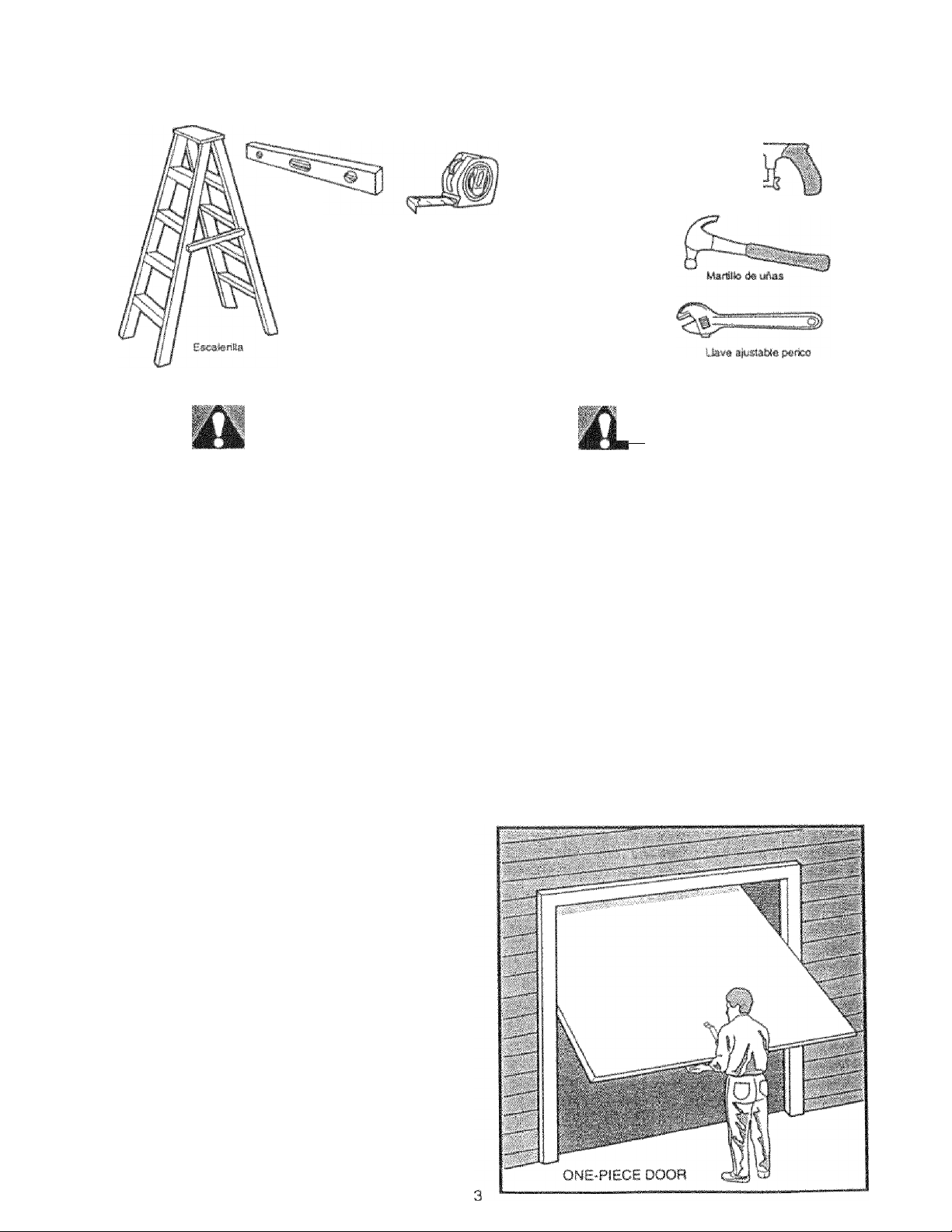
You'll Need Tools
D'uring assembly, installation and adjustment of the opener, instructions will call for hand toots shown below.
tJpz
Pia« d«
carpWera
1*1»
Taladro eiécirie*
Fte*6metfo
3/tr. ШШ. f
Bm'Bfsern
Ища cortada«
Pimm.
Mm &m seguete
ишшй cié «¡а
Ля unbalanced garage dom might not remrse
when required and someom under the door
could Ш seriomiy irtjumd or kilted,
ff your garage door binds, sticks or Is out of
balance, call for professional garage doorservice. Garage doors, door springs, cables,,
pulleys, tmcksts and their hardware are under
extreme teaslon and mn muse serious iniury
or death. Do not t.ry to loosen, move or adjust,
them yourself!
Hopes left on. a garage door could cause
someone to- be-co-me e-.nMfig.led and kH-led.
Remove all ropes coreiected to the do.or before
Installing and operating the opener.
Identify the type and height of your door and any
special conditions that exist and any additional
materials that -may be required by referring to the
lists on page 4 or page 5.
Desaw!a,*r
—
To avoid damage to the garage door and
opener, disable locks before Installtag and.
operating the opener, U-se a wmtd scre-w or nail
to hold loc-ks In the "O'pen." funlocked) position.
Operation at other than 120V 60 Hz will cause
opener malfu-nctlon and damage.
Before you begin, complete the following test to
make sure your door is balanced, and is not
sticking or binding;
»t rft the 'i 'or '(bout haii/ray a., shown R<4e I'-.e the
boor !t otmulij Slav :n pia< f, .uppcxted f nerelv by
lía aprifigC.
• Raise and lowe.r the door to see if there is any
binding or sticking.
Í I
'i.J
i !
Page 4
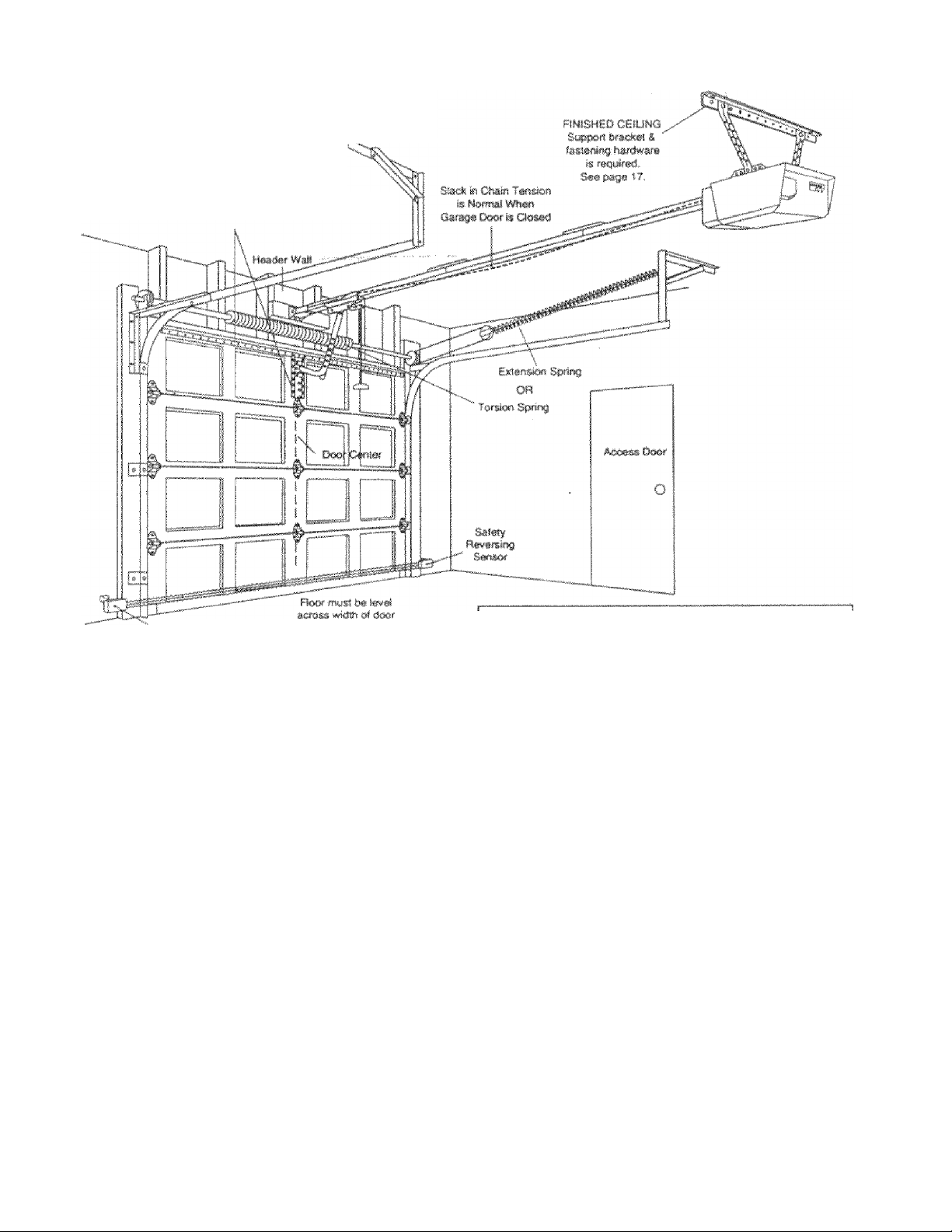
' SEC-llOf"’iAI„,0odr ínstallaííosi'
Before you begin, survey your farag-e area to
see whether any of the conditions ijelow apply
to your Installation.
Hortzorit*! and v»fiical rwnfofcsm««
Is r»«jed lot !lf hiwBí^íit 'gaiag« émm
(fttxirglass, sS»«!, abiwnum, cfcof with glass p«r*ts. ete.|,
S«^ fmg» 24 Im detals.
- Safety ftsviirsirtg S#awf
Bijr.cd on yr,ur porhculos rC't|usrC'rnc'*nlo, there art
íViverai instalLition step'.» which rnighi call >or
rnatiinals arnJ'''rjr hardware; not incliidod tn itie ccirtttn
• Gle;'( 1, parjo id ■ Ltiok a! it>e wall of ceiiinq al.'ove
)iie garage '.íoor. Tire header bracket rnuGl be
íiíK-Lifoly lastooed to stfuolural supports.
• oiep 5, payo 17 - Do you have a finiíthed coiiing in
youf garage? ff so, i\ support bracket and
additional lastoning hardware may be re(¡uired.
• Safety reversirig sensor, page 21 - Depending
upon garage construction, wood blocks may rirt'd
to be facionod to mounting Socatfons before
sortGoro art! inst.ilierl
• Step 10, page 22 Alterrtaic floor rnounfirtg of the
safety reversing senscjt will retiuire fiardware not
provided.
• Step 11. page ,?4 - Do you have a steel, aiutninum.
fibcrgltiSG or glass panel dottr? if so, fwn/onlal
and vertical feiriforoemcnt is requirc-d.
» Look at the gamge door wftere it nieeis the floor
It must close on the floor all the way across.
Other-wise, the safety reverse system may not
work properly. See page 30. Floor or door shouki
he repaired.
Closed Position
■ ^Brar'líiíít
C >\
I rní'ífy
P-‘.\
, . Cúiingf'
¡’ Dí>’'í / I
A ' ¡ I
/?/ ''-"'‘"i"“
‘ ÍHíXX
Am
/z
f<-¿ (Zar^í^i
ÍVv)<' fifiickcü
Hie opener can bo inistaliifri within 2 ferrl of the left
or right of the door cenler if thtrre ic a torsion Gprlng
or center bearing plate in the way of ifte header
bracket or door bracket area. It your ciorm has
extension springs, the opeiier must be insislloci
in the center of the da» Sec pages 12 and 24.
’ Do you have an access door in addition to iftc
garage door'? If not, Model 53702 Emergency
Key Release is required. See page 38.
’ if your door is more than 7 feet high, see the longer
rails available on page 3H
Ar'ft
You may find it helpful to refer bade to this page as you proceed with the Instaftatlon of your opener.
Page 5

LìciCfi" -CHI bnCir,, curv'-y your garagi^ Hfi-a to
see whether any of the canditioas Deievr oppiy
to your Insîaiation,
Slack in ctaifi tens«»
is fWfi«»l when
gafage ikm is ctesecl.
- y'' „ . S4>i!'
'if rj'Xjf mus; 1/“^"
Bi'iced on youf p;jrticulai ferjuifernents, there am
rnyeral snnîcïlîiition steps which might C3!i fur
nuhenais emeVof harily^are not included in the cadon.,
» otep 1, pi-jge 13 ■• Look at the wait or coiling above
!t:e q.iritge dour The lieadof bracket mus? be
i.ecurely faslenftcJ to ■‘.îr'ucturrai suppofts.
• -SLip t). page 17 * Do you tiavo a fimched coilinn in
your (¡.ifage-'’ If so. a support brrjoket and
sKlditional fasteniny ti.ardwaro («not uufipiietj) rn.iy
be required
• Dafoty reverainy fienaor, p,iqc PI - D’Pponding on
garage cwnetrudion, wood blockr. may nf;ed to be
seciirely Jaatoned to mounting locuiicrtc before
sensors <arc; instailed.
• Step 1Ü. page 22 ~ Alîernaie floor mounting uf the
safoty leversing sanfior will rer|uire harriwaro thaï
ÎS not provicJe-d.
• Step 11. piige 25 - Cseneraliy, a one piece door
doers not require reinforcement. If your door is
ligimveighî, you atn refer to the information
relating In cectiona! doors on page 24,
• Step 11, page 25 - Depending on your door's
construction, you might need addiitonai mounting
hardware for the door bracket.
• Do you have an access door in addition to the
garage door? If not, Mode! 53702 Emergency
Key Release is required. See page 38,
• The gap between the bottom of the garage
door and the floor cannot exceed 1/4".
Otherwise, the safety reverse system may not
work properly. See page 30. The floor or the door
stiould be repaired.
FINISHED CSilMG
Ss<3}»« .briicto
S fasi suing
hg/rfwart » r«|ttiii»d
Se«»^ 17,
Closed Position
G. i&ln
f-rai!
J.
O'sraQi
O.îOf
“T-friCii-J
Gti(î*jW CurrftKl
ÎAK-r rxx)i
Ann Arris
V
I
!
r,rw»ÿ«nsy
nolo»*
Rope S Mandli
One-Piece Door With Track
rf
k ■' •■•lTv '
uD, .^"31 i
mus? t>? tev®!
Closed Position
'vy\ " Dwi Stfasght
8rackb“l Ooor
You may find It helpful to refer back to this page as
you proceed with the instailation of your O'pener.
hr-. ......
AcrirîsD
E * n]
' ■ Sô'OîY
'AVj'tfï O?
ntiaso
Rfik^aso
Rpp® & Htrsdl#
kfm
Page 6

Opener Carton Inwentory
Your garag-e -door O'pener is pacicaged tn two cartons which contain all parts illustraled below. If anything is
missing, carefully check the packing materia!. Parts may be 'stuck* in the foam. Hafcfware for assembly and
installation is shown ofi page 7.
UmMM SM24 (f|. S3637 {2!,
S363S (2}, S3629 (t.53626 (2'}.
S34.2:5 P), 5332,5 {1}'
Three-Functitm fterndte Cwtroi
wiffi Visor Clip ('f'J
Modal 53623 Oflif
Tiir#«-Futia!op
Compaa ftmnam Gixitrof
Tro*®¥
Myipi' -,:uvr~,
5 « VI * V.'rt 'i HP's 5'. V'
M&del S3S2S only
Singte-Fufxaion. atiw-i# Controt
witfi Vis«' Qiu m
Z-CorKtaaof
MI Wif*
tf W
Mitdr
gm
i:
I
M'i i«rl 1 VW •^r, y
K()yl*'‘4a i ¡«ly
o'c;' 1.
•V: y;w/ii,k,;"i
¡.f
,,jri>L>d S!,;v,n
W;j|l :,<ii (('}!
Jin* H,irW.,)ia
a'-'
r-mii
End Seciions
r"
Cabf»
Py-ltef Btiii*«
w"
.w
Maim 53637,
.53635. & S342S,
IJfhtiij Con»fci
Wall Co«fOl
IWsjM Wai CortliOl
n I
■ isip
PAUCkot
Safety Re¥«rffl:ng ■Sm»Sf
Youning Bfack,et
With Square H<J*s (2)
Safely Rave-fSin,g Sensor
Motinli-ng Braoleet
WWh Slol (2}
!*■ Jiji ’ S<
Cufved Dom
Aim Smskm.
Safety
aitd
iiteni'lMf*
Door Plal#
•C* Wrap (2}
Oiain mnd CabI»
in D)'sp«ns.infl Canon
(2) Sa.f»t R«f«is«9 Sensor*
11 S«f>#ng Eye m41 RacirMng Eye)
2-Condii«« Wh«.i! S Whluffifai* B«l Wir#
with
SB*«.
Cyr"'
y*.'» r 1,'t t’Vjrfiji
Maftsift'g Btacksis
if.
Sirai-ghi 0<w
Aim Socllof!
Page 7
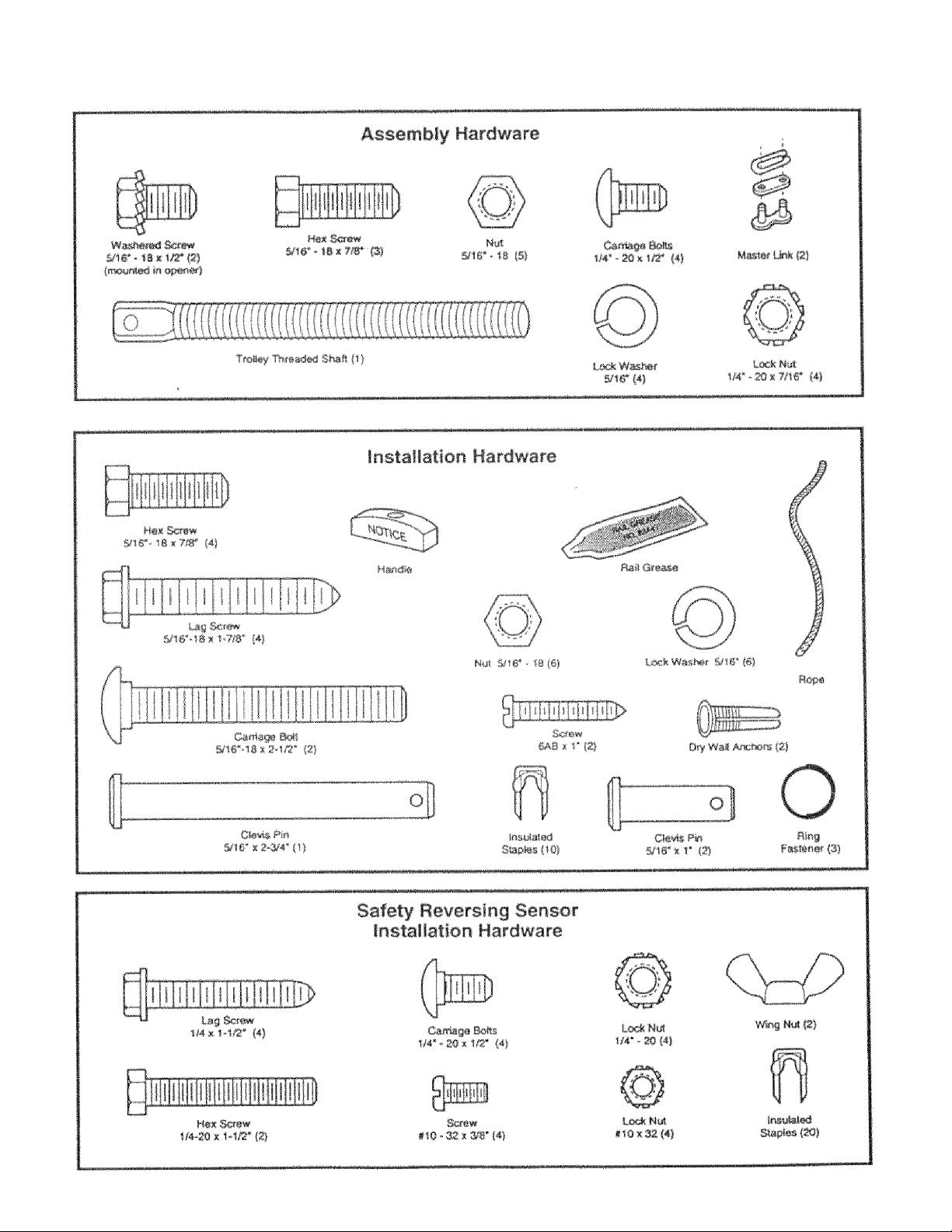
Separate all hardware from the packages in the rail carton and the opene-r carton, as
shown below, for the assembly and instaliatlon procedures.
Page 8

Assembly Section: Pages 8-11
To avoid installation difficulties, not run the garage door opener yntH instructed to- dO' so.
Assembly Step 1
Assemble the T~raii & Attach
the Cable Pulley Bracket
Align the 3 T rait secnons on a flat surface exactly
as showiu The end sections are identical, Make
sure the “arrov^ label* on tfre center sedion is
oosntinrj lov/ard ttw door,
In.'aat tfie carnrifjt- boit-C so ii-:o square brjit nocks
seat in Ific- .'■rquaro holes in the Tsai! end sections
and pass fhruug.h ttiO round holes m T-rail cerrter
sndiuri. Assemble lock nuts, ensure alignment and
tiqhton.
If Tmaii is not assembled
EXACTLY as shown, trolley
wilt not travel snsoolhly
along length of rail or It will
his against tfie nuts.
■Hake S'lire i»ft weeks are
seated in the square
holes and rails are
atlffiecl before yöw
tif iiteii lock nute. ($e#
right and wmm§ views).
Impro^r assem&lf -can
cause feity »alley
of».ralon, iioiss aftcKsr
nul«rice- reversals.
Right Wrong
T-flÄli BÄCK
(TO OPEHEH)
T-RAIl fttOWT
iTO DOOR)
• Position tie cable pulley bracket on -ftie front end of the
T-rail as shown. Fasten SKurely with the hardware.
/ ' -
Uli
CaKe Put«iv
Brat*«
1 T
'CTJrr;
toe!« m'&mm
S/ir
Mill
snr
Hardware Shown Actual Size
LOC*Nut
wr - 20 * ?m‘
■HB* SCfW¥
5/16* - 13 X 7/8*
Right
Wrong
Nat
.506*-18
When tightenliif
the screws, be
sure to keep
braclcet parallel
to the rail.
Otherwise, the
rail 'Btaf bow
when opener Is
operated.
Page 9
Assembly Step 2
install the Tmliey on the 'Tornii
Hardware Shown
Actual Size
Attach the threaded shaft to the trolley with the
lock washer and nuts as shown.
loci«
SIS'.
rmn
Hifi^sded
Irsfler Hyi
TfoI!ȴ
r' .J
to
iltey
'm
to
Loc'k Wash«f
&'tr
' As a temporary stop, msert a screwdriver into the
hole in the front end of the T~rail.
• Slide the trolley assembly along the rail to the
screwciriver stop,
If trolley hits against any nuls en the T-rall, the
tjolts and nuts were atttched from the wrong
side and must t» repositioned. Review' Step 1.
Assembly Step 3
Fasien the T-rail to the Opener
• Place the opener on packing materiai tO: protect
the cover. For convenience, put a support under
the cable pulley bracket.
• Remove the (2) 5/16*«l8x1/2‘ washerecl screws
moynied in the top of the opener.
• Align the hoi-es in the back section of the T-rail with
the holes in the opener.
• Fasten the rail with the (2) wasiiered. screws
pnevtously removeci. Tighten securely.
Remember to- use only these screwsl Any other
screws will cause serio-us damage to the opener.
• Insert', a 5/16*-18x7/8* hex screw iii'to- the trolley
stop hole iri: the T-rail as shown. Tighten securely
with a 5/16* lock washer and nui This screw limits
trolley travel in the UP direction.
n
To fasten rail, use only those screws meiinted
in the top of the opener. Any other screW'S wit
cause serious damage to the opener.
Washefiid Siittm
S/l6*-10»1i2*
Hix Screw
5/ir-l'8*7/a-
\
Page 10
Assembly Step 4
Install the Chsin/Caüíe &
Attach the Sprocket Cower
II n , ,i .1
IHI:
^9
SertO'ys ln|urf can result If fttigers b-ecom#
entangled In moving opener sproctet. Attach
sprockei cover securely. Never operate opener
while yoyr hand is near the opener sprocket.
dv# Chain arttfCaW«
,n',Cf fH‘ ffftnsing
3 ( Anr.u V, ¡Jíf/i- rt Knhmg.
1 mVfI ' ' )i n ÌCIf *f<
• D.-t.rh t;if 1.,'iiíií- !nu(. from the cartoli and íaMoTí it
to tht- {folfi-/ wítÍ! il íii.i'jrif link fíOíTi the hardwrjte
bag bet .Twclm ImK piocedure, f-'tguro 1
• W'tbi tito dt'tlcy ag-iin it the ecr»>wdnver, diepenoo
the rabit around !ííh pulSoy.
• f’i(x of'd book tifound tfie opefrfif sprocket,
F igu.’f 2 Uo auf" rprockot toiith crigage bin
chain Continui' forwtiid to the trolley
thre,idofj sliah, Figurr,- 2
*' b , ‘ [ i f > j- M J « t <1. Í if i O ’ji H I
th*’ ciifiin P) ttio flat end of the phaf!
Check to make sure the chain is
not twisted.
• Remove the scfewdrtver.
f b|‘ ■- *p SiJii
! I» k
FIgyfe 2
Op€fi^
Sp'ocke
Figure 3
!ns.laJl Chain and Cab»
Ffonf Tab SW
in. This 0if*ctiOf>
Spfocfcet
Cover
Baci« Tab Sfot
Tep of 0|jen«r
Master LJnls Proe^eiiur»;
Push pins of masfef ink to
ftfoygh «ijle hxip and hole i.o
front end of trolley. Push ca.p
over pins anc! Into notches.
Slide ctip-on spring over cap
and ito .notches until both
pins are sasorely locked.
To attach the sproctet cover.:
• Insert the back tab in the opener slot. Squee-ze the
cover slightly and insert the front tab in H-m '.tot on
the mounting plate.
10
Page 11
Assembly Step 5
Tighten the Chain S Cable
• fjpin tho ir.hor fiut and lock •ooshcf dovvtt ttv
tKro ifiO'l .haft, a'.va/ titan îtio UnlO'/
• io liijhien !l(0 chain, turn outof nut in the fiiritction
iuhawn As you turn the nut, keep the chain
from twisting.
• When the chain is approximately 1/2* above the
base of the T-rait at its midpoint, re-tighten the
inner nut to secure the adjustment.
Sprocket noise- -can result ff chain Is either too
loose o-r too tight.
When installation is complete, you may notice some
chain droop with the door closed. This is normal If
the chain returns to the position shown when tiie
■door is open, do not the chgiii.
NOTE: During future iiialntenaiice, ALWAYS
pyll the emergency release handle io disconnect
trolley before adjustin-g chain.
Outer Nut
im
mmrn
Chain
B»» o< T-riljf
Ifinef Mrt
You ha¥e now finished assembling your garage d-o-or opener. Please read the fo-llowlrig
warnings befo-re proceedin-g to the instaiiation section:
IMPORTANT INSTALLATION INSTRUCTIONS
mm
Wm Y '
lo redyce the risk of se¥ere injury or deatli to persons;
1. READ AND' FOLLOW ALL INSTALLATION INSTRUCTIONS.
2. Install only on t properly bafance-d and'lubricated garage door. An improperiy balanced door
may not fewfS'-t and could result in severe Infury or death.. Repairs to cables, spring asscmbiies
and other hardware must be made by a professional service person before Instaiiing opener,
3. Disable all lo-cks and .reroo've alt ropes cörmected to the garage- door before Instaiiing the opener.
Ropes conriecfed' to a garage- door can cause entanglement and death.
4. If possible, Install door opener 7 feet or more ab-ovt floor with the emergency release handle
moyn-ted 6 feet above the floor.
-5. Do not connect the opener to po-wer so'yrce yntil Instructed to do so,
6. Lo-cat-e the Wall Control within sight of the door at a minlnium height of 5 feet where small
children cannot reach and away fro-ro. all rrtO'vin:-g parts of the -door.
7. Install the User Safety instru-ctlon Label on the wall adjacent to the contro-l button, art-d the
M-alnlenance Instruction Label in a prominent fo-cat'lon on the- Inside of the garage door.
8. -Upon corop-letiori: of the installation, the door must reve-rse when it c-o-mes In contact with a
one-inch high object or a 2x4 laid flat on the floo'f»
9. Do no-t wear watches, rings or loose clothing while Installing -or servicing m o-pen-er. Jewelry or
loose clothing can be caught in the rRechanlsm of th® garage door -or the opener.
11
Page 12

Installation Section: Pages 12-27
Installatioo Step 1
Determine Header Bracket Location
Instaliaiion procedures vary according to
garage door types. Follow the ¡nstruclionij
which apply to your door.
■ SECTIONALDooratid ■: ■■ i
' ONE-PIECE D'Od'rWitfvTrack!
Я
wimmuQ
If the header bracket Is not rIgWIy fastened to
a structural support on the header wall or
ceiling, the safety reverse system may not
work properif (see page 30|. The dom might
not rewerse when requireéf Bnd eúulá cause
serious infuty or death.
The garage door springs, cables, puileys,
b-raclcets and their hardware are under extreme
tension, D& not affeinpf to- loosen, move or
adjust them yourself. Serious perso-ml m/urf
or death could result. Call for professional
garage door service.
• Close the doto and nuuk ttie irisido
vertical centf.ifiint* * oí the tpiraqo tJoor
• Etxierid the imo or,to ttio hcrrider wait
above the
Remember, you can fasten the
header bracket within 2 feet of the
left or right of the door center only if
a torsion spring or center bearing
plate is ill the way; or you can attach
II to the ceilinq defer to page 14)
v/hen clearance is minima!. (!l may
be mounted on the wal! upside down
if necessary, to gain approximately
1/2D)
ft you nviH to :пШ11 !hn hcadof Ьпчскс!
on ¿1 Px-t (ibi wuli <>i oaHmc}). use ¡ap
SCfCnv: (fluí t.ltSHPn'CÍ! U) oncufely hvjfnn
ihi} Px4 to r.Uuutiiu! curpotts ,}>■' shown
hern ,inij on fury - ÍP.
1
*Opon '/ou< to the- higfti-'ol
fiufnt ut iritvel -io '"tiMwn Draw
¿in intur'.,<.;;'tsng t;frri/jfital lino
ofi “!o- hoador wiill ?' atiovo
tiro tiifjh pnfot rtsi','. naight wiSi
provida travo'l oioarrH'ice for tfici
top cdgii <'i t!if; door.
Door .olraranco brackets mr,
avaiiaWo fra sor.tKrnat doors
wbon treadriioni cioarance is
less shall ?“ See acctisoon/
page yp.
Proceed to Step 2, page 14.
Ь n'l
Ceitng
Heed«
_.W*I
— 2‘- Trac*
а'Л' '
■ у Sr
,r
Higbtsi Pant
о1Тга¥в1
Sectional doo-r
with curved track
12
One-piece door
with horizontal track
Page 13

■•frack■ ]
Read the Safety instryctlons on page 12. They also apply to- doors withoo-t tracks.
Hoisd^'^r WiiJf
I ' ji, \
............ GuMeiiin«
' Cióse the door aod mark the
inside vertical centerline of
your garage door. Extend the
line onto the header wail
above door.
If headroom clearance is
miííimal, you can instnl! the
header brackel on ihc ceiling.
■MA p.i'jn 14,
• If you need to mstaU the
header bracket on a 2k4 (on
wall Of ceiling}, ma lag screws
(not supplied} to securely
fasten the 2x4 to structural
suppútis as shown.
C-r>llOMAL a-!LJMG MOUNT
Fon KCAOEfi eRACKCT
► •'.y«-"-,: P-oini
t> i r,t^ei
»fji ;; ?
iC'-
t h- 't’
I
a -
/
/
One-piece d<>or without track
jamb hardware
* Open your door to the highest point, of travel as
shown. Measure the distance from the top of the
door to the floor, Subtract tfie actual height of the
door. Add
• Close the door and draw an intersecting horizontal
line on the header wall at the determined height
If the total number of inches exceeds the height
available in your garage, use the maximum
height possible, or refer to page 14 for celling
installation.
8* to the remainder. (See Example),
pivot hardware
EXAMPLE
Dist.inco from top oi door
(,ir highest point of travel) to floor ..........................92*
Actual height of door
Fiemainder.....................................................,.„,.....,.......,..4*
Add........................................................
Bracket height o-n header wall .....................
(Meas-ure UP from top of CLOSED door.)
...........................
-8^
Pfoceed to Step 2, page 14.
13
Page 14

Installation Step 2
Install the Header Bracket
You can attach the header bracket either to the
wall above the garage door, or to the ceiling.
Follow the instructions which will work best for
your particular requirements.
Fasten the Heade-r Bracket to the Wall
Centof lire btackot on the veriinnl guideline with
the bottom edge of tfre bracket on the horizontal
line as shown (vrith the arrow pointing toward the
ceiling).
Wall
»4
StfOCWOl
Supjiort
Highest
Pisift-t of Trsvisl
(of Garagi Door}
Verticai
Cenier
Una
Mark feiiher sf-it of bracket bolci) (do not use ihc
holes clesignaieci for ceiling mount). Drill 3/16* pilot
tioies and fasten the bracket securely to a structural
support v/j!h the fiaidware provided.
La0 Scrftwrs
S/ir*!8J<1-7/r
TS# naii hot« » iof
mtf-. Ym musi u-t lay out)'» su
omint fli«t N5wJ»f Ijra-chst
V
O'pBofial
Wail MiMntteg
Mote*
Hardware Shown- Actual Size
1 ! j ! j 1 1
F—
!
1 i
i/i6*-ia * 1-7/8*
IjagS«*»
Wall
Fasten the Header B-racket to the Ceiling
■ Extend the vert-ical guideline onto the ceiling as
shown.
Center the bracket un the verticai rnaik, no more
than 6' from the wall. Make sure the arrow ¡a
pointing toward ffir,' wall. The bracke! can bfj
fnr.jijntod flush ar^jainsl the ceiling vrhon dearrsnee
«0 minirnal.
Mark holes dfeugnated for ceiling rnntiri! only Drill
3/16" pilot holes and fasten bracket securely trj a
strtictura! support With the hardware provided,
Msl} s'j M-'! j'Fbi=’J
Th« n,i . f 7 • , ,r fX' ■ ’ M Vi I !i(tU
You n 1 'IV i ■; iij >ixi< ill
<l" >■ I '■! ijf ' e !
m
i:
_
......
........ _
Crfltef:
Vert:c»l
Caisisf tin*
tag Samws.
14
Page 15

Installation Step 3
Mttaeb tfte T-mil to the Header Bracket
\^\ HivA-tl
-7''\h
7
j-» / ' \ X
• Position the oponoi on the ^jaracje floor below the
header bracket Use packinr) maleriaS as a
protective bas«-
If the door spring is in the way you't! need help.
Have someone hold the opener securely on a
temporary support to allow the T-rai! to clear the
spring.
• Position the (able pulley bracket against the header
bracket.
• Align the bracKel hokis arid joiii witii a clevis pin as
shown. _
• Insert a ring lasiener to secure.
../.jarage
Door
lii
Hardware Shown Actyal Size
O
Clwts Pin
S/«* It 2-3/4"
IS
Tflmporafy
' Support
O
Ring FsJstetiet
Page 16

Instaiiatlon Step 4
Position the Opener
Foliow instructions which ispplf to- your door
type as illustrated.
■k 2x4 laid flat is co-nvenlent for setting an ideal
door-to-T-rall distance.
• Raise the opener onto a stepladcJer.
Fotr wHt nmd help at this point if the ladder Is
not tali enough.
• Open the cioor alt the way and place' a 2x4 !aJd fiat
on the top sectio-ri' be-neath the T-rail.
IÍ file top paml Mis the tmlley when you raise
the dmr, pull down m the trolley release arm to
dfsconmet the inner and outer sectlms. The
tmlley can remain disconnected until Step í2 Is
comptéted.
To prewent daniafe to steel, ain'minuni:,
fiberglass or glass panel doors, do not rest the
opener on the door withoul ysing a 2x4.
T-fail
IE
2*4
T»--;-—--3^
a t, ,
Slepacfcfef 4 1
Trolley
I
vVilfs the iJoof !utly epen anej parallel to the floor,
шеаоше the dictunce fiorr. the floor to the top ot
ilto dijfjf
Uriny и oiopladdfif as a rtippoit, ms« the operier
to Ihi: same distance a?> ttie door from the floor {it
vnii bo at a oitijM arigio as shown).
Tfie tr>p ot the door -should be level with the top of
the ofiener. Do not pcssition ihe opener more than
2" above itiis point
I
1Г'' c;
1" Í '4 Hr! _
■ f \ 1
, 1 '1
i'"(\
: ij
¡ Нвалг
Hi.w.U'!
-—
’’ it.
tei|- tof '"fpíTit.M
'Í ‘
if \
'4 \
//
Ш
1:6
J
Page 17

Installation Step 5
Hang the Opener
Two representative insiallaitons are shown.
Yours may be different Hanging brackets should
be angfed, Figure 1, So provide rigid Kupport, On
finished ceilings, Figtrre 2, attach a sturdy metal
bracket lo otruciura! supports before installing tne
opener. The bracket and fastening hardware are not
supplied. See accessory pngo
» Measure the distanci! ironi ouch nde of ttie opener
lo tfse structural support.
» Cut both pjecers of ifie fionging t)racket to roquirod
lengths,. •
• Drill .'4/1C" pilot hot*, s in Ifii- '.Jrur.turnl fiuppCifl'
» Attach nnn <■'’0^ 'd c.'ich bracket tf> ’ f uppor; with
b/1h‘x1 //8' l.'Hj ;ic.rows.
» Faster! tfin uporstc to the hariqi’ig braukets wilii
ГУ16’.13хГУв" 'jurewe, lock ?а1оЬ>.'г.с and riutc
»irtiGck to make сию die i ■ c«! u, сд.п?огг;с1 over the
door (i,>r in line r;th ihe hem Jar t>r.""ckpi (f thn
t/rackfii !c not ct-nicTod eimve the door)
• t{amove rhv Fod oum tiic. iifjcr rriannally if me
rfoor flits the reel, CJ!C'- ficrinra brtickn!
'.T
Thé opener oould fall зт1 mjore someone ¡t ;t
is not properly sccun.'iL Farrfen ihc oponor
securely to structurai supports of the- garage.
Figure 1
'■ bir'“ufdl
, \г;р)Г
^ ! i <* ?
1Ч-1 G
u. U ‘ ff Л
W trf i ^ ?V
ги/ f' fhf
Figure 2
Grease the lop and ynciers-ide of the
rail surface where the trolley
slides. A tube of §.rease is
supplied.
Support
HHiSirt tf oi li \Wj
' /VS i‘ H'vi»'’
mi/'fr ' hu
17
Page 18

Installation Step 6
Instai! file Waff Control
t.4 in ,n!.-iîiO,', Ht ífi u:>‘ f ¡.¡i f<! Wif b'*!l
■//.'П f vnti' >'h* i.’j' ' n-’.v t<‘rin!ii. J't
h tSii '■ttiif W I'r-i HhlHi 1() H )inj
Ah-ltti/fBiJ lu I,
» Locate the Wall Control within sight of the door
a! a minimum height of 5 feet where small
children cannot roach, and away from all
moving parts of the door and door hardware.
Farden the l.iglded Fusli Button Wai! Control
r.t cure!’/ With fiABx 1 ■ 1 rcmwc 1 t’.e conr.oie
•'•iyir; и Â'.\, t'-AB.xr И (пСаНшд srUo dtywatl,
nríll Mih" fuiS*';.'. afid u-,t- the njir.lirr',. prnvMjed
• íA.jn ihe h'C-li wiib' up tha- Л'.чН and t.’iu ceiling
1 r ífí>.,’ opomn IJi.i; iirajiated огарки; !o rmcure the
Hi r,i,;veï/j! planer Рп',’ careful ni.d tu pieice tfsci
wife With a ntafde, ííüpehy гесаИшр in u ciiod,
• Receiver terminal jcrews and the antenna are
locaierî orr tfie back panel o! the openoi Position
!rto aritoitna w>rr: as shown
• Then cc-nnect the bell wire îu the oponof tc-miinai
r.crewr,: îo T; wtiife/i(;d to 1
• Remember to affix the User Safety irtstruclion
label to the wall near the Wall Control, and the
Maintenance Instruction label ш a prominent
ïcentior. rn the inside of the gdrcigc decr.
if the label снТ'и;- „ivu will nut adhori-- iic yuui д.ццдо
wall puriaise foi fjivr.omus ioir.u wiiti ftnic;) use tacks
to s-''Cijrf; îh<;; Pthoi afangsidri !lv;; w'r-.li confroi.
FsKjO df' uipinirc: tiuw to Ofji.riatc’ ifW; f/pt-ne? using
t.he liqîiîud pijidi bar r,f buticn, аь wd! ,r,‘. tfsc LewA
and I iiifst tuatun-';;; v<ii tfic Delswu vV.,¡i r,^o''ftiu!
Children O'peraling or playing with a garage
door opener can Injure themselves or others.
Tlie gara-ge door could close and cause serious
mjijry Of deaths
Install the Wall Cortirol (or any additional push
buttons) out of the reach of children and away
from all meving parts of the door and door
hardware, bof where the garage door Is wisibk
Do not allow children to operate the push
byttonfs) or the remote controls).
A moving garage door couM щит someone
under It Activate the o-pener only when the
door is properly adjusted, you can see It deafly,
and there are no obstryctlons to door travel.
Do NOT cùrmeot the power and operate the
opemr at this time. The trolley will travel to the-
fyll open position: but will not return to the
close position until the sensor beam is
connected and properly aligned.
See Safety Reversing Sensoc insiryctions
beginning’«! page 21.
Q-yidoor Kef Switch Accessory Connections
To- opener temiinal screws: white to 2; white/red to 1
LighlecJ Pus-h Button oem^e Wal! Control
Wall Control Lighted Console Wall Control
Hardware Shown Actual Size
fjlii iiJ,Ti,d::'jJ.liLiL
^■AP S ; K" ’ч
t к I'.n ,
Í V ’ ' ^ ' 1 *
Р.ДП Í 1"
, •:, í'.- 'A’jÜ ' î-'i-J
üghttïd Console
Wall Conifo!
U'r4.<î itRwf '
rV.iii Acru fj-
L ■
iZiz
Detee Wal Control
tightect
ftjsfi ButtOifi
Wal Control
.
.
Back PaniiS
of Opener
Ope«f
Tefminil Screws
Anfefl« -
18
Page 19

installation Step 7
Imtatt the Light Bttd the Lem
Install the lights
- Install a 75 wait rruiximum light bulb in the scxtket.
The light will turn ON and remain lit for
approximately 4-1/2 minutes when power is
connected. Then the light will turn OFF.
• if the bulb bums out prematurely due to vibration,
replace i! with a standard neck "Garage Door
Opened* * bulb.
Lem Gyitte
U§nt l*M:
install the lens (excepi for Model 53225)
• Apply slight pressure on the sides of the Ittic, and
slide the tabs into the slots ¡n the end panel
• Reverse thé procedure to rerriove the lens.
Installation Step 8
Attach the Emergency Release
Rope and Handle
Lew Star
7S W« Ma*.:
Uoht Bulb
I
Do not use fhe red hanclie to pull the door
open or closed. The rope knot coald become
untied and you could fall. Use the emergency
release only to disengage the trolley and. if
possible, only when the door is closed.
Garage doors are heavy. If the door is open
when the handle is pulled, Ihe door could
close inadvertently if it is not properly
balanced. Serious injury may result to persons
under the door. Make sure the doorway is clear
of persons and obstructions before pulling
handle when door is open.
. emafgancy
Reieasif Handte
• Thread one end of the rope through the hole in the
lop of the red handle so •NOTICE’ reads right side
up as shown. Secure with ao overhand knot.
The knot shoyld be at least 1 " from the end of the
rope tO: prevent slipping.
• Thread the other end of the rope through the hole in
the release arm of the outer trolley.
• Adjust rope length so the hanclie is 6 feet above fte
floor. Secure with a.n overhand knot
If it Is necessary to cut the rope, heat seal the cut
end with a match or lighter to prevent unraveling.
13
Page 20

Installation Step 9
Electricai Requirements
To rr;dU‘:o tho nak of oiooirfo ;.;hock, your garago
door opt-fU!f har- a grounding type plug with a third
grounding
type outlei.
!l the plug doesn't fit into the outio! you have,
contac.1 a qualified eiectrictan to instaii the proper
outlet.
pin. Tins plug v/ill only ht into a grounding
To pmmnt eiectmmtton or fire, Instaliatlon
and wiring must be In c©tnpli.ance with local
electrical and buildlrtg codes.
Oo NOT use an exlenslon cord, 2-wlre adapter.
Of change the plug fn any way ta make: It fit
your outlet
To awoid instaUatton difflciilffes,
do nat run the opener at this time.
If permanent wiring is reqoirecf by your local code, refer to the following procedure:
To m.ikr> ,1 pfrnicmf'fU connc-ction through the
7/'8” diameter tioic m ihn top of the opcnei
^according to ïrcat corJcr
• Remove Itio opener urver screws and cet the
cover aside.
• Remove the attached 3-prong cord.
• Connect the black (itne) wire to thé screw on the
brass terminât: tie white (ne-ytral) wire to the
screw on the silver terminal; an:Ci the gfo-und wire
to the green groonti: screw. The opener must be
gmunéeé,
• Reinstall the cover.
'©
Right
Wrong
To avoid imtalMtim difficulties,
do no! mn the opener at this time.
20
Page 21

Safety Reversing System
iiiferination f ou'll need before yoy begin the installation of the safety re¥ersing sensor.
The safety reversing sensor must be connected
and aligned correctly before the garagi door
opener will move in. the down dlrectlo-n.. This Is a
required safety device and cannot be disabled.
instaltaiion procedures are the same for sectional
and one-piece doors.
Without ê propertf working safety reversing
sensor, pêTsom (particularly chIMren} muté
te Iniumé or Mlfed' by s elmlng f amfe door.
Read and fellow ali instructions.
To protect small children,: install the safety
reversing sensor so that thé beam will be no
higher than 4'*'-S*‘ above the garage floor.
Disconnect power to the garage door opener
before Instaillng the safety reversing sensor.
■
Be sure power to the opener is disconnecfed.
The sending eye transmits an invisible iight beam to
file receiving eye The units can be instnised on
esthet Ride ot the garage door as long as the sun
novor TihineG directly into the receiving eye lens.
l.ook at the label on the connector end of each case
ÎO identify the sensors
The hiackcT-R rminî be connected and tar,toned .so
that the sendifig and iecetving eyes lace each otiier
as I’hown m rigun,; t
If an ohstnict'on breaks the light beeun while tfvj
garage cl-nor ie ckvrng. tfm doo' win .ief/ md
re''er.se t" toll open pnritiort and the opcmei lights
will flash ÎO' ‘3 seconds
Ttio brackets muiU be sccurtdy fastened to a soiirj
surface such as the studs on either ssdc: of ttse dour,
or aiJd a piece of
ma.ronr/ consbuction
■| tie invisible light beani palli гпигД be unobctructed
No pad of tho garage door {or door tracks, springs
tsingoG, roiiers or other hardware) can interrupt the
biioni wfiile Win fJtvjr IS rk.irariyi If it does, uRc a pieu,of wood to bnitiJ Tiut each scTiSor mouRiiru.; юсрДюп to
itio гтшп10!;'| dopih roc;uired for iight fv>am i:‘earaii<:f‘
wood a! each locrstior, if irsatallinq ifi
Sensot Seart
4.€* max.
шьлт Itoor
\
\
M) « i r i .3f5T,
4 < ’ fit ’ Ï.
(Hr''- i.jI’T' - - ■■ ^
.tlilL 1 I'jht dêMiT
Prôiætbn Атш.
Figure 1: Facing the door from inside the garage
21
Page 22

Instailatlon Step 10
instali the Safety Rewersing Sensor
Figures 2 and 3 show a;i.~ernbiy of brackets and
“(7 wrap based on tfie fccommendcd instaflaiion of
tiio sensors as sftown on page 21.
However. Figures 4 and 5 arc; variations which may
fit your trsstailatiott requirements better. Make sure
the wraps and brackets are aligned so the
sensors will face each other across the garage
door.
• Fristen the “C“ wraps to ttie mounting brackets
riavinfi square fiole;;. usinq the hardware sfiown
¡II Figure 2.
• Connact each accernbly to a siortfal Lirackot, ur.snrj
ti'se hordvvaru ufiowri hi Figure 5.
Note the alignment of the brackets for left and
right sides of fhe door.
• Finger tighten ihr, lock nuis,
• Use bracket niounting holes as a templale to
locate and dnii (2) 3/16’ diamclor pilot holes on
both Sides of the garage door, 4"-6* above the
floor biit no! exceeding 6‘. (See warning on
pa.ge 21.|
• Attach bracket asse-m.bltes with iM'xl-l/S“ lag
screws as shown in Figure 3.
• Adjust -right and left side bracket assemblies to the
same distance out from the mounting syrface.
Make sure all door hardware obstructions are
cleared. Tight-e-n the nuts securely.
Figure 2
Figure 3
■iÄWÄ;
^ J 'U
««»Ä5 ifack'tt
>i ur (¡ ^ f,K l-f *
/R K ,H HoF'h
tM * 1-1/2* M*m % IS* CsiTiBg« Bote
lag Soripwii {wBfc .s<iu.ari shoohtefi
WÍ® Slot ^
•C* Wr#P:
Moorting 8r»cK0l
wfth S<|u»» Hotos
Figure 4
Alternate Wat! Mount
Mijonting S-faeket
with Si«
youiitfftg 8racfc«!
Witt! Separi Hole*
C'Wrap
Ssnsor
with WÍT#
¡■«lical&f t,%ht
Figure 5
22
■mate Fl-oor Mount
■■. BSof wSti wtr*
todicaiof tight
FIOöl "■
MoMoting
with Síjiia-rt Hci)«ä
' . with S1«
Bracket
Attach with
eonere-l» ancho«
(not piwid«d}
Page 23

• Center each sensor unit In a *C' wrap with lenses
pointing toward each other across the door (see
Figure 6).
• Setsjro ';en&ois with hardware shown. Finger
tighten thrj wing nut on the fecewing eye trj allow
for fiiiaf adjust me fit Securely tighten the sending
cyev/ing nut.
• Ryn the wires from tX3t.h sensors to the opener.
Use insulated staples to secyre wire to wait and
ceiling,
• Strip 1/4* of insijfalion from each set of wires.
Separate white and whitoAiack wires sufficiently to
connect to the opener icrrniria! screws: wfiite to 2
and whife/biar k to .1,
• plug in tt'ic openoi Make au.'t; the Lock Feature is
oft. Cireun irnficatoi iigiiis in botft die sefMiing and
fftCf’iving eyes will glow rJoddily if wiring
conticcitons and afignenent are correrd,
If fhe ifvJicatdr light w off ¡n the receiving aye (and
the invisible light beam path is not obstructed),
aligornoni is tniymed.
• loosen the receiving eye wing nut to allow rdight
rotation of unit, Adjust sensor verticalIv anri/or
horizontally until tl'ic green indicator light glows
with a stcijdy tight.
• When mdicafor tights are glowing steadily in botfi
units, tighten tfio winq nut in the receiving eye umt.
Figure 6
*C* Wrap
indicato
1/4-20 X W'fi'
Trouble Shooting
If the sending eye indicatijr light rl'e-s ’>• -t g/ow
•fftoiUi// attor li'ct-jliatiori, shw-k fci
• Ueclnc ¡.'ower l-r ifir- .jpe-ner
• A sfom in the wfitfi.» oi wtittu/block wiius ■¡lim.e
cart occur uinto'r .stafiins ra at scu'W turminal
ftonrKmtions.
• Incfuiect wiring betweert gensuf;, and ffpenur
• An open wire iwiift bmnki
!f fho scrisjtni] eye indicator light glows
the roivtvinij eyp <r’.rii>kitor ligfit d-.w* jilt
• Chuck dliqnnirjii;
« iChf'oK tor iin Ofjun Wifr* !c tin- M' .uiving ay*'
Hardware Shown Actual Size
1/4-20 X MS*
H. U I
M '1
h
Bell Wirt
■o'..,
: In S I
(4 '
K>
-
F>f»sii#a
CtiiBfif
.
Figure 7
Will WlW
I lit I Ir
I 1,11 • , n .1
Wat! Gomrerf
COfSliiCitonS.
fdoned Itrs«)
V-,.
■ -~i
I
Smmi
CommSimt
OPENEfi. TtHM'INAL SCREWS
assssBS
!.TVir„bt<i I I'jM Bean
Pii !|i>eion Are.s
23
Page 24

I'listallatioii Step 11
mm
Fasten Dom Brackei
Polle-w instructions- which app-ty to your door
type as illustrated below or on page 25-
A horlzo-ntat brace should be long enoygh to be secured to- 2 vertical: supports. A vertical brace- should
cover the height of the top- panel.
The liustralten -shows one piece- of angle Iro-n as the horlzontaJ brace. For the vertical iraci, 2-pieces of
angle iron are used to create a "«"-shaped support. The best solytion is to chec-lc with your garag-e door
manufacturer for an opene-r installation door felnfercement Wt.
..........
To prevent damage to steel, aluni-lmjin,
fiberglass or glas-s panel doors, always
reinforce the Inside of the doo-r both vertically
and horlzontaJlf with art angle Iron,
Figure 1
* Ccrslur thfi doof bracket on fho '.■r.fVUHioly marked
vfMti'.a! c|üidü!ino ur.ort tor the tierKlo! brackol
inotr'-ilLitiun.
« Position ttsc bracket on llie iaao of the iIoik 'viSiiin
tl-r' t-olkwisKj lirrritc;:
A) TiiL lop edde o! Ifu:- bracket ff'-r imkaw the tof>
'’dry: of the docit,
fct 1 hi- top odye 0! t.ho bracKot Oirectly b«:-low any
;jao-tuial ouppoft acro-c.n tite top of the dfior,
» Mafk -m-.l drill 5/16" Icii and right fardening holer,.
/'.omirr,' If 10 brackot an aho-wn in Figuro 1 if Ihom ir.;
vmiKad minlurnerncnt,
It your inchailation doeon't mquifo vcrticri! resniotcoment but doer need top and botlorn tardening hoies
for thü door bracket, position the tjeor plait- over the
doi,ft ta'ackef a/, sAjWi in Figert ;j Fori'en ct.-curc-ly
wiiti foucKvare; nhown in Fsqiift 1
Hardware Shown Actual Size
NUI 5i16‘ -18
Lock Wasitwt S/16*
Orriaig* Bo«
s/ir-ia * 2-ie*
Figyre 2
24
Page 25

Please read and compiy with the warnln:gs a.nd reinforceniefit instryctlons on. page 24.
They apply to one-piece doors also.
Hê»m Witii
• Center the b-racket on the top of the door, in fine
with the header bracket as shown. Mark holes.
• Drill S/16' pilot hole.s and fasten the door bracket
with hardwa.re supplied.
If the door has no exposed framing, dritl 3/16* pilot
holes and fasten the bracket with 5/16*x1 -1/2‘ lag
screws fnoî supplied) to the top of the door.
The doe-r bracket way be .Inslalled on the top
edge ol the door i required for your installation.
(Refer to the dotted tine optional placement
drawing.) Drill 3/16" pilot holes and -substltyle
lag screws (not supplied) to fasten
the bracket to th® door.
Fo-r a -*»i wth m
«*po»d or fa
Ï» optlenai inslattelon.
urn mê'xMir 1*6
scrtw (not swppi«!) to
fasten cj«)r bfseliai-
. Gaffiag«- Bcstt
Sfir-1Ss62*ia*
r
25
Page 26

Installation Step 12
Connect Door Arm to TroNey
Follow instryotions which apply to your doer
type as illustrated below and on page 27.
I ''SCiCTIO.NALXioprs'Orily V:''J
Make sure garage door is fully ciosizd. F‘uli !he asriii-njency re:oa;u! handie to di-inonnufl tr.o outer trollef
from the inner trolley. Slide the outer troiiey back (avray tioco ihu door; about 2" as 3h0‘/,n in
Figures 1, 2 and 3.
Figure 1: Figure 2:
• Fasten '.itiaigit! doo) arm sedion In otrter tfolley • Brirsq .urn o«o5ton'j togeihfu ¡'»«1 tw<> pnire of fic>!ect
With a eiovie fan SriCere tlii' i.iinrHCetion wifti n iitir; tt <*! iinc; up arid |ofn ; ectien;. deieet no tar
tastener. an -ft an [»>'■.csbie to ifirr*' r »' doui -hm, siyatity
* Fasten r,!i!vc-'1 'jeoi urrn !o 'Jio dor>r hnirKcrt in the
same way an ..iiirwn.
Hole AligrwTiertt Alternatlye
Figure 3:
• if tiijlr.r;. in cijfved arrri are ahovi* hides ¡n straight
oint. rji'xonriect straight ann Put about 6“ trorn
the solid end. Heconnect to trol!»;y witti cuf cnii
do wn ;\ ij shown,
• Bring arm eoctionr, togettrof
• Find two pairs oi lioSes tiéii bne up and joirs with
sttrews, lock ’wasiiert; and r.uic.
Proceed to Adjustinent Step 1, page 2S. Trolley will .re-en§age aytomaticatly when the opener is operated.
26
Page 27

Assemble the Door Arm:
• Fasten the straight and cutved door arm sections
together to the lorigesi possible length (with a 2 or
3 hole overlap).
With ttie iluor closed, connect the straight door
arm section to ttie door bracket with a clevis pin.
• Secure with a ring fastener.
On one-piece rjcxirs, Ре!пге i;onrnx:!ing the door arm to the trolley tho travel limits must te adjusted. Limit adjustment
•cre-A's are located fv, the Lift side pariol m; etiown on pag»' 2P. Follow adiuGtnionf prctodurec below.
Fulf Ctos#tJ
Tftsiley
Огюг
Bracket Q,
Ciem- Pin stmighi
AfilJ
Rir>e
Sc««» -
-----
Lock S/ie*48
'МШШШ
^
FiJtyOpei
Twltey
N«l#
I t
Oosf Айв
J ) 0«f Aim
* I Cafineaor -Moie
СшЫ
Dow Afrn
С!©ш1
Door
Open Ooof
Door with
Ba-ckwereJ Stent
Door Atm
Aipstment Procedures for One-Piece Doors
Open Door Adfustment:
Decrease UP limit
' Turn the UP limit adjustmeot screw countBc
cicicicwise 5* *1/2 iurns.
' Press the Wall Control posh bar or button. The
trolley will travel to the fully open position,
' Manually raise the door to^ the open position
(parallel to the floor), and lift the -doof arm to the
trolley. The arm should touch the trolley just in
back of the do-or arm. connector hole. Refer to the
fully open trolley/door arm positions in the
illustraiion. If the arm does not extend far enough,
adjust the limit further. One full turn squats 2* of
trolley travel.
Connect the door arm to the irofiey.
* Close the door and join the curved arm to the connector hole in the trolley with the remaining clevis pin. It may
be necessary to lift the door slightly to make the connection.
* Secure with a ring fastener.
» Run the opener through a complete travel cycle. If the door has a slight “tackwafcJ" slant in, full open position
as shown in the illijslration, decrease the UP limit until tho door is pafallet to the floor.
Turn iite DOWN hniit cdiuOii’eni screw ciackwcm 5
complete turns,
■ fttRsc the Wall Control push bar or button. Tho
trolley wii! travel to the fully closed position.
' Manually dose the door and trit the door arrsi to the
trolley. The aim .ttiould touch the trolley just ahead
ot the door arm connector hole. Refer to the fully
closed trotloy/doof arm posiiior.s in the illustfation. If
the arm is behind the connector hole, adjust the limit
furtfier. One full turn eitunls 2' of trolley travel.
Closed Door Adjustment;
Decrease DOWN iimit
27
Page 28

Adjustment Section: Pages 28 - 30
Adjustment Step 1
Ad^usl the UP and DOWN Limits
Do not make any limit adjustments until !he
safety reversing sensors are completely
insfailed.
ijfTiit adjustment settinas regúlate the points at
winch HK' d>')Oi valí stop when moving up or down
The door will stop in the up dirfiction if anything
ifiterlores with door travel, The dcor wdt revorsc in
t!if d’lwn direction if anything iníc-rferoí'. with the;
travel ‘mdudiriy bindnKj cc unbc'tanccHl Р01>г;':).
to operate tho uptmic, píí-'-n, U,e W-aii tTonlro! push
tail Him tbo Dpenot dsr'./ugii sj (.ompicte iravoS
eyeJo '
• Dues ihe dot« upen and сюае ujmpleiely •'
* ¡JOOS ttm ciuor stay dosod and nut revorse
unintentionaily when fuSly closed?
d your duO( passes ЬоШ of thoca tests, гш limit
adjustments are necessary unless ttie reversing tes!
fails (See page 30),
Ш
Improper adjustment of the tfawel limits will
interf'ere with the proper operation of the safety
reverse system. The dmr might not reverse
property when required and couU seri&mty
Irtiuie ar kitt mmmm under it Test th# safety
reverse systtm following all ad.Jystinents to the
travel llmis. See p-ape 30.
Atlitsimenl
’xl-IL__
//
Й)
\ \
Lift sm Рлт
Adjustment procedures are outlined below. Run
ryf'M
each adjustment
Repeated operation of the opener during
adjustment procedures may cause the motor to
overheat and shut off, Simply waif 15 minutes
and try again.
RCriri tfiG p!Tv;cdur-c, > jccfi/lly í.'cfof»? proccodirig In
Atlyjctmonl .Stej) 2 a ccir-wdnver to mak»,' limit
u'ijijsinsonia
How and Whmn to Adjust the Limits
if the door does not open completely
but opens at least five feet
sfi- r>; SC'- up travel ii,r>r hv' i 3 1>” r »* iis'-.ifn- :it
' ,ff w f loi KwiC'“ lAt* *'an t'ui .jH of If.wel
if door does ftoi open ot leas! 5 feet: Adiuct th'-
ilH (lifvvii ♦'■'ii (' oc e/plj!ho‘i ir. Adjo'tmerit Ht* p 2
If the door does not dost' completely
ini r-v) o i/ouu tfovoi rariift UiAVHlHn!!
.i (jiictirK'n! ci rew' aoufiti n ior;!" v o One lum
( gn,it‘ V" uf tr iV‘*l
if ijmv c!ill W'lit Uoct i ifopi'/'-'y t! / ivo'jthijfsr.q
till' aim if' sgi' )
H ytj) h iv. I Jiuctf'l ifi<* 'loor ..'III to Ifie rr a^imuni
!ef/]tb and thr; fT»of ‘.till wiii no' • Loo f'onipLtoly,
ioA'iT ‘he iHM'Jer H,-t 'j<' lie talirdion Lfep 1,
pciyos 12/ i 3.
«CREAS* 1МСЛМе,
í ктт «f» {
j-mvB.. 1ШШ.
Щишшт Libel
If the opener reverses in fuily closed position
E)ecroace down travel Turn the DOWN limit
adjustment screw siockwi.ee One turn equals 2" of
travel.
If the door reverses when closing and
there is no visible interference to travel cycle
If the opener lights are flashing, the Safoty noveroing
Sensor is ob.structed. Ffemovo ihe obr.tfuction.
Test the door for binding: F*uH the c-rnergent-y le
handle. Manually open md dose the door, if the door
IS binding, call for garage door son.iico. if the door is
not binding or unbalanced, ij'jjust the DOWN (close)
force. See Adjustment Step 2.
28
Page 29

Adjö'stfnent Step 2
Adjust the Force
Force adjur.tfTicni coritroSs arc kicated on the back
panel of the opor;er, F'jtce adjustment settings
reijuiat,,-; ttsi: amour« ct power regijirod to Operi and
dose the tJoor
The dour will stop in the up direction if ariytfkng
intetforou with Its tiovoi. The door will levcrse in the
down riiroctmn if ¿ìnytfnng tnlerfores with its travo!
(ind'jciirig bif'.ding or unbalanceid doors),
(Í the forces rtro so* too ligi it, door travoi may bo
inlerrijpled i>y nuiuancii snversnJs irr tho down
diiecirjn .if'd ■Popa in fh<; ly) ditection, WcattiOr
eonríiíioít*'; 1..ЧП ,ifled the- (Тюг movement, so
ironasionai a Iju-Cfncnt may he rieudud
rtie maximum torce ruijuctment ranne ю Thu degreer,,
about ъ:а of a ocenplnte turn Du no! force controls
beyond ttiat fmint. Turn forerr iitliudment controis
With a screw jnver
WARNItTti
Too much fore# on the d'OOf will Interfere with
the proper operation oT the safety »vers©
system. Tfte door might not rey-erse property
when required and couU seriously Injure or kill
someone under it Do not increase the force
beyond the mlnlrmim amount recjyired to close
the door. Do not use the force adjustraents to
compensate for a binding or sticking gartfe
door. Test the safety reverse system following
all adiystments to force levels. Sm page Ж
Bück' panel oí
doöf i^ner
fmm
Ad|ustni#f(t
Coftt/ol
iil)!;, I -'.lyiSif: "ÍÍ-.
AdjtetmsBt Lafref
How and When to Adjust the Forces
Test the DOWN (close) force
Grasp ttio dOi)r bottom when the door is about
halfway Shrougtr DUWN (dosei travel. Tbu' door
sfiouid r(?vc roe
travel docs not guarantee reversal on a two-inch
obstruction. See page 30. if if;e door ¡s hard to
bciid ’jr d.uosn'l reverse, decrease thi? DOWN (dose)
fOiC'; by turmruj tho contrrj! crjunterdockwsoe
Make 10 dogrtru turn ;sdjiistmoms urrtil the door
roveises normally. Alter oacti ridjustmenl, run tire
openor through a complete* cycle,
Test tho UP (open) force
Grasp ttio door bottom wtren ilio door is about
haSfwav througti UP iopejri) travoi. The door stiould
stop. !f ttie ihxrr IS tiard to hold or doesn't stop,
decreac'e i jP (opcin) force by turntnrj the control
counterclockwise.
Reversal halfway through down
Make 10 degree turn adiu.cmwiiiis until the door .stops
easily. After e.acii nd|ustrrseni, nm the opt-ner througfi
a cornplele travfil cycle.
H the door doesn't open at least 5 feet
Increase UP (Open) force by fuming tho control
clockwise Make 10 degree turn adjustments until
dorsr opens ccanpletoly. He-adjun! the UP limit if
necessary. After each adjustment, run the opener
through a compieto travel cvete.
If the door reverses during the down (close) cycle
and the opener lights aren't flashing
Increase DOWN (dose) force by turning the control
clockwise. Make 10 degree turn adjustments until the
door completes a dose cycle. After each adjustment,
run the opener through n cornptelo travel cyde. Do
not increase the force beyond the minimum
amount required to close the door.
2Ö
Page 30

Adjustment Step 3
Tcsi The Stifety Reversing Sensor
‘ tSv; rerfK'.io irc/ntfCfl push button to opvn tho
docjr.
• FhrKf; Ibo op'OiOi carton in tho putti of thu doce
• tbfif.ft t!te retT'sote control push button to clone tibe
dfxif J7)o door WIÍ! not move more than an inch,
and the opener light will flash.
Professional service is required if the opener
closes the door when the safety reversing
sensor is obstructed.
The garage door opener v;i!l not cióse from a
remote control if the indicator light in either
sensor is off (alerting you to the fact that the
sensor is misaligned or obstructed).
Tile ijaracft: <1oof r:an ht 'used by pressing and
huiclitiij the Wali Control push bar or button uritsi
down tinvol ir, com¡)letf'd.
.
...........
.....
Without a pmperif working safety rewsrsing
sensor, persons (particutarfy chJUrenf maid be
seriously Injured or killed if ieapped by s
dosing, garage' door. Repeat this test once a
iftontii.
¿d:
Si.f«iîÿ' Rtv©'fS«9 S#r^of
I
Adjustment Step 4
Test !he Safety Reverse System
Test:
* Placp a u.v- ¡rii’h bcoud (os a 2x<1 laid liab cm the
! ofii'.-rod iinilr.'f the garage door,
' Opof.'itf,* * the do')' m !t.e down direction. The door
must reverse on striking the obstruction.
Adlystment:
¡1 till - dora c.-r, ll'.o I'diSbuction, «î rs noi itTivoiiiiy
far Ciuouqfi ;;i îhr> rhovn dirf;f;îion.
• Incroas.; tti,> nO'/TN limit by turning the DOWN
limit ad|u';truf;'!t ocr*;*w counterclockwise 1A! turn,
* fTcpoal îfm
On a sectional door, make sure limit adjustments
do not force ttie door arm beyond a straight up
nnd down po!' ition. See the illustration on page 26.
• Wlfun tfio d'îor mvemes on the onenneh troard,
minovu liiu ubr.ir'jcbrrn and run the opener througfi
-T or 4 concfhr.if; trove! mycie.î to test adjustrnen!.
If the door will not reverse after repeated
adjustmeot attempts, call Sears Service Center
for garage door opener service.
n warming''
-
Failure to test and adjust the safety reverse
system may result In serlcms injury or death .to
Repeat this test once a month and adjust as
needed.
V i
Important safety check
! i ' IH) '' I
Repeat Adjustrnont Steps 1.2 and 4 after
tjf Pt'OI ,tUi
1 I'.h til IjU
■/ iimii 1
Any (i-p
fin t’J lit
■’n/ rf‘[
An ' (>‘p air to^ or a
ttfw n!
ii.'i
)0'f
r. nt ,f
ig :springs
tn M' (,
air
iljm trtii fit w
, ,"nd htff'i.V
r Mí' ) 1 f ‘h :0 oar<
1 ji (Mri r '4 t trif .
30
îefigîl
r tl -i _
m-'î
t f If CM
1 ; i.p 4
s';m 4, t -
Page 31

IMPORTANT SAFETY INSTRUCTIONS
_
WAUmUQ
/fv WARNING i
To reduce the risk of severe injury or death to persons:
1, READ AND FOLLOW ALL INSTRUCTIONS.
2* Do not perralt children either to- operate or to play with the opener. Keep rernole control In a
location Inaccessible to children.
3. Operate"operter oniy when the door Is In lull view and free from any obstryctton. Keep the door in
sight unill ¡t Is completely closed. NO ONE SHOULD CROSS THE PATH OF THE MOViHG DOOR.
4. Checfc safety reversal system monthlf.. See page 30. The garage door MUST reveme on contact
with a one-fnch (or a 2x4 board laid flat) ob|#ct placed on the floor, tf an adjustment Is made to
either the force or the li-mit of travel, both adjustnicnts may ise needed and the safety reversal
system myst be checked. Failure to properly adfust the opener may result In severe inlury or death.
5. If possible, yse the- emergency release only when the door Is in a cto-sed position. Caution should
be taken whenever the disconnect eord is actuated with the door open. Weak or broken springs
may mme the -door to fall rapidly^ causing injury or death to persons.
B. KEEP GARAGE D-OORS PROPERLY BALANCED. See page 3. An impmperty telanced door may noi
reverse when requimd and could result In severe Injury or death. Repairs to cables, spring
assemWi-es and other hardware must be made by a professional garage door person.
7. Disconnect the electric power to the garage door operter before making any repairs or removing the
covers.
8. SAVE THESE INSTRUCTIONS.
Care of Your Opener
Limit and force adjustment controls
Limit Controls Force Controls
15!2
A.i,5)U ifr'""' ^ i .«id'l
VI N-fi
Weather conditions may cause some minor
changes in door opernfion requiring sortie -re
adjustments, particutarSy during the first year of
operation.
Fhtge;; 2B and 23 ¡etor So fite lirriS and force
.idiiiútrnciit;;, Only a screwdnvm is required. Follow
itistnjriujns cari‘fii!(y
Repeat the safety reverse test (page 30| after any
ndjustment ol limits or force.
Once a Month
Manwatly operate door, tf it is unbalanced or
binding, call for professional garage do-or service.
Check to be sure door opens & closes fully.
Adjust limits and/or force if necessary.
(See- pages 28 and 29.)
Repeal the safety reverse test. Make any
necessary adj-ustments (See page 30).
Adjwstrwiot Lais«l
fi.ocaied on this righi Bid« partat|
M:aintenance Sciiedul-e
Tti-e rein-ote control
f hi; >nU’ ' V 4'ii h!"' (.* 1>. ' Í ,ii‘ ri-'V, rfl'iot"
'■..F.hoi n ,r; . iiO// l.j pr. .'IC'fO /HJf
r<‘ ‘ ! /»,! t'tj h( , ,i|! O'!'' I if roi jt'ir d ■ If
f iVlO" ' f 0/ !• > < .4 II Í' Í O ■ ,roftl' n.Ji 1 If
i|! i t /1
> : <-i, I
The remote control battery
The green test fight should glow and the opener
should operate- when the remote -control is activated.
If the gre-ert test licjh-t is dim or does not come on,
replace the battery.
The 12 Volt battery should produce power for at least
a year.
Dispose of your old- battery properly.
Twice a Year
Check chain tensten. Disconnect trolley first.
Adjust if ne-cessary (See p-a-ge 11).
Ofic-e- a Year
Oil door rottefs, bearings and hinges
The opener does not require additional
Iwbrlcatlon.
Oo not grease the door trades.'
It Ifi'
31
Page 32

Operation of ¥оуг Opener
Aiiîviüc îhe о|,^епс‘Г vAlh any of the following;
1. The Remote Control.
* 3-Function and Compact: ! icid ¡¿vgc pu'-Ti
cfov-Ti uniil ihc; (lo-or f.tart': to rnovn
* Single (unction: Moki pmki bntton nritis fhr- dour
rdOrlO to inOVU'
2. The Wall Control Hold puuh. bar or buUori down
until ttm 4nti{ Gfart'. ti* move.
3. Tile Key Switch or Keyless Entry.
(See Accr;s:;oricn)
When the opener is activated witti the safety
reversing sensor inslailed and correctly aligned;
t H operi, rho door Will cur.ioo, И сНппЗ, î! will орог!,
ir h rioung, tl'ï'u do.; г w:ll roversi..-,
I! мрггшпгр the door vvili siop (akowing сро';>.; ìur
'■nUy iind nxii of polo and for mi}.
4. If tin; d.>or iiftr, been stopped iri a parìsiilly open
pO.Piticsii, It Will closr:
5 If fdjsîniidr-rj while closing, the rJoor wti! revorne
6. if obsta'cteri wbde operting, tfie rim^f wiii stop.
7. Tl re garage docrr wtl( reveme ir; îiio dosing cyde when
IÎ1C invidbir beam iO irroken, If fnity operi, »hr- dfv>f vali
tii'j! tJosi, v'twm ìlio beam u. I>n;>kf;n Iho ;',(?n;;.or has
no efii;ct tri ttiO opc-niry;} zyclc,
и tfso :k-u‘aìì î:> iruî sf.suiiied tjf >‘уу> aiujïin-t,! cuimctiy,
tiit; di.,'01 ?/r,;rs‘f :Jor>; f,4rm any funiotc- cofrirol You can
rrlosç the dora witf'r t!* Wall Contrid. tfre Key Switch,
or Keyltms Frthy. hr)wever, if yni; acfiv.ite them uniil
0OW/Î travel III cnnifilote И you r'Yu.i.'m itmm loo soon,
the wiit rnvcioe
4 fw; ;.1рмг,ог tifjiifi; will blink Un 5 uo’iandn when tficr
¡■•'Yo'y 'u-vro'enri boru'.crr causer. ‘Tie tloor to reverra
The Opener Lights wd îtim on ¡mder tiw foiiuv/inrj
condittnnv УЛгоп tfii; Opener is irsitiatly plurjqcd in, whan
Uio petwer fs inierruptfd, when îtso opener tr activated. It
W1Ü turn off autornatiually after 4-LT minuier. or provide
crjrudant lii'jfit wfion the I njhl Ipaiun.* lu acîivaled Bulb
us/c- IS 7b watts, Fn;-r/!nmm
Weak or bmkm springs couM allow an open
door to- fall (etth-er rapM-iy or unexpectetlfyl.
-resulting in serious injuryt death- -or properly
dam.a-g&. If possible, use the einergency
release rope and handle only whm the door is
fully closed.
To open the door
manually;
The rJuu' .vfruuld be
lully dtj;-od if pormiblC'
t''ul! d; w.ri f'.M', Ibt: red
r;merqi';n(.;y retear.e
handle and lift the fiocif
manuaitv 1 o
reconnect the door trj
iFuW [Vj^u)
Manual disconnect
position
The lockout feature
prevents ttifr trolley
from recrainoctisig
‘.H Pm[[ fhf'"*
t.'rntjrgcncy htjndh?
down and back (ttjward
the op'Cneri. The dCfor
ran iheri be rarsed and
lowered manually a&
often as necesitaiy. To
dr.'tengago tfre lockout
foaitire, pul! the
emorgency handle
etraighi down Ittfr
trolly/ wtll rermnnect on
t!<e next UP or DOWN
operntion
the opoiK.v. presr, it''e
Wall Cf'.rilroi ptich bar
or buHori
T'Owards C^*o*r)
Lockout position
Operation of the Wall Control
Pnm.e Till tsuiitH'.j ii,it vr butten lir Open r r
cinse if if? don,г
I'rerv .'igriin to r'f’W.v.vL* the dfx'ir duririg Use 'insuig
c'/do fif to ,‘ïi;y? tiv? cioof wtiile it‘o openiiiQ,
Deluxe LighiecJ Conrrote (mode! 53824 only)
Light feature; iT.,*;;-'? the ( ight I'H’tton. If ift.."- oper'icr
light ti: off, it will turn on.
If iho opovior lifjfit is ОЛ, ir,-v<jn in the 4-1/? rniriutc;
aiiî'jin,’,jîîc cyclop it v/iii turn nil
But if you nur ¡tie light butti>n to turn thi* ligfi! on
and than aclivab? 1‘ie oporicr, the light will turn off
uftitr 4- I/O fr.inuîes.
The; t fgfit bidton will rio! i;<j!ifr.ol tfto opevifir liyfiî
wiion ttic (ioo! !C in motion.
Lock feature; T'tie l.ock foatufc i.c dadgned to
prevent operation of the door irorn pnirtaLile remote
LTiritrolio Hriwovfci. the dexsr wiii open :tnd close
ffoni the i)olijxe Wall Control push bar. the Key
Switch and the Muiti-Funetton Keyter.v LntiV-
To activate: Press arsd hold the Lock biitton lor
2 socondn Til*.’ push bar fiejW wsli tiacfi as long as
tlio lock feature is on.
To turn off: Ptor.s and hold ttie Luck button again
fur 2 seconds.The purit bar iiutit will ;>top flashing
Nurtr.al uperalion will resume. Fho Lock foatufc will
also turn off wfienover ttio SRT butlori on the oponaf
end ff.inr*! ¡0 .icfivated.
32
Page 33

Receiver and Remote Control Programming
r, a\¡¡\/ rV'U' rulí'íi modiijcat^orio oi this
re*'"iV-;8 trar:.i5e pifo?
the code or r*íphii,,inq the baftorv. THERE ARE H0
OTHER USER SERVICEABLE PARTS, '
Models with 3-funcÜon remote controls; The
remoto controls') has been tariory set io operate
With the Inrge push button. However, you can use
eiltior of the two small fjuHons, if you prefer. And,
the 34unction remote control(s) can also activate
additional garage rioor openers and/or light controls.
Below are instructions for programming your opener
to matcti the rjther buttons on your remote crjntroi;;
and any additionrjt rornote controls you may
purchase. -Soe availtiblu acocssorimi on paye 33.
Models with a singfe-function remote control;
ihr- go rape door wiii oporato v/ticn you press the
rernute rrontrol pusti bution Ketor tu tíie infurrnattrjri
below if yrai want to add a 3-funoiion remote control
or erase vuur programmed oodu.
53000SRT Series Garage Door Openers
(With "SRT" Button)
Your *SHT" gararjo door opener will upttrate with as
a.any ar, four YiRT" portabie remote controts anfi
one Muln Function Kovlos::, Fintty,
àk WARNING:
Children operating or playing with a garage
door ope-ner can Injure themselves or ethers.
The garage doa-r c&uld close and caus-e
serious injury or death. Do not allow children
to operate the waif pysh bu-ttonCs) or rem.ote
contfol(s).
A. moving g-arage tíúor could Injure' or kill
someone under it Activate the openef only
when yow can see the door clearty, It .Is free of
obstructions, and Is properly adjysted.
Figure 1
Single Fonctien
Mini 3-F«nctlon
Remote Co-ntrei
Sei-eci a rensof* ieftifot push
Ewtion to- opemte opermr
Remote Contro'!
To Add A Remote Control
1 Select a remo'i:] control puaf; bultori to operatrr
tfie recf'ivi.a
2 and /w.'dtf’it; selected rurr»)te cornfol putei
button, Fiíjüse t
T'ften preste and fell-
hack print;! o! tt'in opunt.’i, f
lifjli! Will flush uncú
hJfSV' th‘i opeiim o/ji! upefate wfiun O'ur reiiiute-
controi push button i;, pre.srPid.
If you release the remote control push button
before the opener light flashes, the opener will
not accept the code.
To Change the Selected Push Button
On the Same Remote Control
if you decide to use a different rf;motc coniroi buttonthan oiigini-iliy programmed into the opener, you
need to erase ,s//the learned codec and reprogram
(iach remote contrrj! used to operate the garage
door opener.
To Erase A!! Remote Control Codes
• Press jrid hold tfie ‘TuiT" buHun no the opener
pan«! until the iricJicatur light turns off (about 6
second;’,) AH the codes the opener has learned
Will be erased.
* To (upioijr.arn, repeat 'ilups !, 2 arid .3 for oauh
ramote control in use
tlte
".SHT“ huiten on the
ii';ure 2. 1 he ojtenef
Standard 3-Function Remote Control
Figure 2
Garage Door Opener
(With "SmarT Button)
» J
*Sf
m ineft aite-r
>
;■ 4|k.
емО PANEL
Code programming instructions arc also located
on the opener panel.
33
Page 34

Having a Problem?
Sitaation
The opener doesn't
operate irom either
t!}c> Wal! Control or
the remote control:
Qpemr operates
from th-0 remote
eontrol, but not from
the Waif Contrai:
The door operates
from the Wall Control,
but not ftom the
remote control:
Probabie Cause and Solution
! til'.; opi.T.er have '■•¡''.■airM.; rhu«] a irilo ihc; auilf;!, if it liytií,
ah-.i 'k tfii; iiy'.e bt'n or the Inurtm. tCr/nv.n outSUa an; rarstioSi-.-ii by a wall -iwifrii.)
1 lavr yo'iJ d>„;5b!0''j ali Cj:: uovtew inraoHation inotruoticai waininfjr; on Pipy 11
3 Is íheíK a buiid-np of me or snow nnder the ijoor''' Fho dorii ¡nay bo fro/ort to the
ground fSiinovo any rostnetson
4, The garario citruf spriiig mny bo broken, Have it repiace-d
5. fti’peati'd opaaaííon ¡nay have inpped >he overload proior.tor ¡n ttio rnoior, Wait
15 minutes. Fry again.
1 i tf,. jb . ’ 5 ,! ' oMit' ¡I «.< ' Í it,vO h o b. ii wi" fr.vi d'( >0 !■''!.-r: 1(0 j’ st'w
c> [’bo r'if r nd oil h '•miiiid t tt .orbing both (MmifMi . a b-i iro' Nm" wh. .
of/i' '3ooj.il- Í lili hi 1 k Ííj' a fdUNi/ .Vlfo ' oMiO ,ts ft a’U.o /F J’
' ti.i' tí j ! ''0 uruh " as : irjf , rt brfikofi’Aif--
¿ An> hr' 1 . i ' i f t
1 It vuur rrvxjoi tills Ihr; Lijck feature, ¡«¿ike .sfjre the iock m Off
3. Is any wif! push button flashtr.tp' Your npettor needs to re-harn h rútnotu conlioi
ccido Retfci to Instfijotions or; liio opener pand.
3. the bntiery test iight glow wtien the remede control pudi tiUUon is prí.¡ssod? !f
not, iOplicc- ttif. battery-,
4 Program Ih.n receivrsr to match t,he lom'.fle coritírjí cotie
5 Repeat ttu? 'uccivni pfofpi'irfu'risryj ¡jroccdw'O vath ail remate corit;'.’)l.s
Hi
Vi< W htf'p
0,
p.Kfo IP
The remote control
has short range:
Opemr mise is
distutblng in IMng
qumrttws at home:
The gamgp door
opens and closes
by fts&tf:
The door doesn't
open completely:
1, Check the battery tost ligtil, If ttm light ¡s d»n. replace the b,'!ti>mv.
2 Cftanqu ti¡e kscfstion o* the lemo'tf? contiol in your car,
3 Cííück to bo f.un; ftse .untenna on tf'-o Süle of brick p<a!id ot >.;,*';enO:S fully
downward
4 Srsne iimS.oliatiDfii; rjiuy tsive shcirler r.ongti due to i rTO'tai rji.K.'-g toil bai.Kesi
(.n.Mjli'itiCiii, Oi mota! tjarniie sidinq.
If ojaorai!<)nal ruiise is a pm/blem i;ecause of proximity nf if;(i opriner to !l'■e livinci
qu.'ii'tern, ttio Vifiriiiixi hsolatos Kit 41A3263 can bij insialled. I fn.s kif wds dfoagncij to
rniPüni.-'e vibration t(> tim house and !s easy to install.
1 Be .sure tfiat hIi nanote contrc'l pusfi buttons and battery inrlieatui iKjtiis are oft.
.3. rternove liiS; brill wire fr* «rn tfie Wall Control terminals and opr-raift frcsrrr the minóte
<;ontroi only. If tfss soi’-'O'. the | rritslcjn, the Wrfll Control is faulty (tepkscc). or tfiorc! f.s
an [ntramiaont ihort on ttie 'wtre betwoGn ti'io Wall Control and tfiC C'poner.
1. If the door has been working properly but now doesnl open ail the way, increase the
up force. See page 29.
2. Is sornothing oftsimeiing the floor? FierilOve the ob-Struidiijn or rep.air ’.fw cJoor.
3. If door opona ,ú Sf-'i'íSt 5 toot, th* travel isrruis may need to bo increaiovJ One turn
orilláis 2 metier, of travo!. See payo 23.
Repeat the safety reverse test after the adjusiment is complete.
The door stops tut
doesn't close
compietety:
Review the travel limits adjusiment procedures ort page 28.
fíepeat the safety reverse test after any ad/'iisteeni of door arm length, close
force or down limit
34
Page 35

Having a Problem? (continued}
Situation
The door opens but
won't close:
The -door rewemm for
no apparent reason
and &/xmr MgMs
don't blink:
The door reverses for
no ap^mnt rmson
and MgMs
blink for 5 seconds
after mwerslng:
Probable Cause & Solytion
1. If the opener lights blink, check the safety reversing sensor, ô.m p vje 23.
2, If the opener lights do not blink arrd it is a new installation, check the down force.
See Adjustment Step 2, page 29. Fo-r an existing installation, see below.
Repeat the safety rmerse lest after ttm adimtmeni is complete.
1. Is something obstructing the door? Pull the red emergency release handle. Operate
the door manually. If it is unbalanced or binding, call for professional garage door
service.
2 Oloar any ice 'v snow itom tfse garage tOcr ,шза whore the door dose:',.
;3 fd.-ivHjw üiíi .idîij'Umf'Miî proiVjfiiri;.'-, on page ?f,*,
4 If doiu roronm-, ici i!ie iuHy doüud p.>s\Uo(\. dor rea ju Ihc; travel (раус 2Щ
Repeat safety reverse test after adjustments to force or travel limits. The need
for occasional adjustment of the force and limit settings is normal Weather
conditions in particular can affect doar travel.
Check the safety revefsing sensor. Remove any obstruction or align the recoiving eye.
See page 23.
The opmer fights:
Tho opener strains or
maximum force is
needed to operate
door:
The opener motor
hums briefly, then
won 'i work:
The &p0mr won't
operate' due to
power failure:
..don't turn on:
Replace the light bulbs (75 watts maximum). Use a sfanda/d леек gamge door opener
butb if regular bulb bums out.
... don't turn о fi
ls the Light feature on? Turn it off.
Tf« door n;.ry hv on! of balança nr the орпгнгг ate hrokon Close the door and use the
arrM.aqericy rnWw lo cli-w.t.>ru'V4.1 the îroîtev Оргт, ,'*ги„[ tíoae the Ьдаг manuallv. А properly
b.ttunceíl do'.'.r wiü aíay tf¡ any potni ut traval wfstlo Lw-ing ouppfjftcd entirnly by rtt; :д;'Пгк];;, ¡f it
üne.'-, not, Пг’,connect the ofXíner and cxiil d г/Г'/.-кгуропа! garage drxjr &er,aceman Da not
increase the force to operafe the opener.
1 Thu garage скал r.prings are broken. Se;y above
2. It îhG problem axtira on tire first operation of tfic opener, door may bo tekt'd Ov-ahle
the door кк:к. 1} ttie chain was removed and feinstallcci, the motor may ho out of phase.
F-ternovo îfie cfiain; cycle the nv)tor io tiio down position Observe the drive sfXFXiket,
7/hen It tuma m a dockwico direction arid stops in the down position, reinstrili îfie cfiain.
Repeat the safety reverse test after the adjustment is complete.
t U.v; the ' rrtcrq(;fH7/ rnluaco to dtxonniv.i ttic irolley, Thf. Ьеюг can tc opottfxj and douixl
rraniniU Whn 1 tt'o ^v^wor to rodixi -d, prerx. tfw Wnfl t.tontroi push bar and trolley will
automática.!'/ mronnret íunlefs trolley m m kvikout position ) See page 32
2 The Emorfjency Key Reîtiace ассаоьогу (fur uso on garages with no service door)
sJisconnoidG tbr trolky from outside the q.irage in rase of power failure
The citain droops
or sags:
It is noirnai loi the chain to droop slightly iti the dosed door position. Use the
emergency release to disconnect !ho trolley. If the chain returns to normal height when
the tfotloy is disengaged and the door reverses on a one-inch board, no adjustments
are needed (see page 11).
35
Page 36

Rail Assembly Parts
Repair Parts
AV
C. -
installation Parts
1
1
1
/ 3 ^
1
6
у . 1
La^ a i
KEY
NO.
1
2
3
4 183B110
5
6
7 41B2616
PART
NO.
1АЭЭ5
41А348Э
183117
83A4 Rail grease
41A3473
41 A3534- Rail asssm.b% hardware kit {includes
DESCRIPTION.
Master link kit
Complete trolley assembly
T-rai! - center section
T-rail ~ end section (each)
Cham and ca'bte
Cable pulley bracket ass'embly
NOT SHOWN
hardware illustrateti on p.age 7|.
I
t
KEY
PART
NO.
NO.
1
O'
4 1 A4!rP;
4' ' A-tlioiiA
■3
4
A 1
b
4 ’ A3u;j?
Ь
/
’■0Л14
fi
27C i;4B
41ЛЗНРЙ f fT’f-ft)iinc> rope S (uirKlIi-; aesy
у
21;Л23й
lu
11
12B3S0
120374
12
41A43f>3
13
14
-11 A't373A consoi kit
i УНВЗГ)
1Ь
1 'ГЫ?Л
1/
irT'CiiO
1204154 Gnuare iioic- Ьтски
13
12R4A3
•
;-.o i::fJ4f55
41A3333
■Г.А41 13
11 .i/o hi Я
DESCRIPTION
1
i. Kihit-d wail i.onirrsi
LighiC'd pulii bUdOb wall Г'г.грго!
làinglmhjnctiriri тпг'дг,- .-/'П1ги| ho-using & screw
only {no Circuì! bo.iKjj
h'fiinciicn rcmoic conifol Iwiusinq & screw only
.'3 function compact remoli; control
iiotjcing S .ccrew only
Г'-fionijucìcr trf.’li win; wbitc К wiite/red
Door bracket plate
Header bracket w/cli.-wic pin fuctener
(roec‘>’/sng and cnrriinij оуо-а
Curvetj door arm soution
iightcd wnSI имигЫ
12V battery
FlorTtOtC COnitOi yiCi'!' OiiC
Door brtiokot
A'lth 3‘ "■cf’intiucioi boli wire atiaclied
4 tmiqht dtou arm r;ectior<
Hanginci brai •kc!o
"0“ 'wrap bmeko!
Dlotied brackol
NOT SHOWN
ìri'’4iiìiaii''4! fiarilrt.'iro bm'| (inuiudos hardware
illu .t.Mlmj on p;if|0 ,‘i.
Safely CiOncyf iurd‘A.,iio
i 'iTVi nRiflU-'l!
IS
^ ^ ¡ф, о
14
8
- “13
17
f
#
»
»
•
#
9
г
«
»■
m
«
88
8!
»
&
»
»
«
s
fife
»
%
Ч
»
36
Page 37

opener Assembly Parts
Repair Parts
ICIY
PART
NO.
NO*
1 31D380
41C4220A Gear and sprocket assy.
2
OESCRIPTIO'N
Sprocket cover
Complete with:
Spring washer
Tiirust washer
Fletaining ring .
Bearing piate
Bolt pins ÍCÍ
Drive ge-ir arid wmrr, g(-;ar
Hiriicai gear w/relunci .«ntj
3 41 AifUr
4
4 1E34245
41A4352 tjid panei
5
6 1;58«8
7
108D46
8 3003C3
300387
300306
12A373
9
10 4iA3150
Dn'S'/worm gear kit w, .jraiKio
Ho!! pins Í?)
Lifio cord
! K|hi socket
1 fins
Qipacitoi - 1/? h p
r'kfipaciior • 1/3 h.p
Capacitor - i/4 h.p
(3apacilor bfackot
ffirminai block w/.';r.ft;wa
PART
KEY
NO.
MO,
11 4103058
4IA3474 1
12
*n A:K74-2 Cover - 1/3 h p
4 t A34 74 5 Cover • 1/4 h p.
13
41A2818
41D3452 Limit switch assembly
M
41C439HA
13
in
41C i;m6
17 41A2820
41 *5282.2 A
ia
Vj 41A4315 /0
20 41A3691
41A2825
37
DESCRIPTION
Universal leplaceirieni motor and
bracket a.n.';t!mbiy
Complete with: Motor, worm, bmcket,.
heanng ascrrmhly, RPM si-risor
Cover - 12’ h p.
Helical gear and rofasner w/oreaso
FIRM sensor .issombly
Y/tre tiarnesr, ar/;y. w/plug
Shaft he.irinq hi
Interrupla cup -Lwy,
Receiver logic board assy
Complete with:
Logic board
End panef w/all labels
End panel w/ai! labels
NOT'SHOWN
Opener asseiiibly hardware kit {includes
screws not designated by a number in ius.)
Page 38

Accessories
Sear:» offers rriany tioefui acceoeorte*: tur y<nir c|<jra<je dour opcnor Tltey 'iré iituofrated below with
Senro motJef rHJnib<>r*> and der.cripiiono.
.
.............................
53'02
/> ’
.
Lmerpency Key Release-
:h -;eei>r/f a a ¡,0 ,i<y- ,v3i fd J
, >”i >' 3 AJÍ
53/39
i
■ 1
3-Function Compiict Remote
Crmtrol'
told, ri no: '/f ■:> f: ! :ciu( r'u;
hip
S3703
53704 •
A - '
53705
1 •
53709
! ' ' 1 ' ■'
■ / ’
"} HI ^ V ■ -f
- '? O'
' -, .
Oütdúúí Key Switch:
Opens the garage door automatícaiy
from outside when remote control is
not handy.
8 Foot Rail Extension
To alow an: 8 foot door to open fully.
10 Foot Rail Extension:
lu .'illow a 10 feet ::ky4 tr fyxjn tuliy.
Door Clearance Brackets:
(f c*r Soctionj- Dtjnry Onry)
j ^
fit-place top bf¿i(,:k''ds arsd rollers on
duf>r ÍU ri'nJi >f;« f'iragtil r..! di'n'ir travoi
For usir wt'ton inotaihrip ofionoi in
ejarago wi'i: Kiw headroom
clearance?.
S3?7'3
53774
I
537/6
53/79
. {*.• 1
p, , j
Wire-l-n Light Control:
Controls interior or exterior lights.
Wires into- the electrical box like a
(Jimmer switch.
■
Piug-ln Light Control:
Ci.-tdrol', inh’no'' light-;. Fli.-p'. latri a
■wall Tfyt pfai -i'i
Multi-Function Keyless Entry:
Lnablcc tionsaowra-r t.'' op'hatc
g.uMge ifc'ct f-.ipi.-ner irum ouiydo
by nrsK-nng ( ado on sphCiaSly
dociijmi'i koytiuaid.
3-Funclion Standard Size
Remote Control.
Inr-ludoy vifh’i iiip.
53714 Support Bracket:
For finishwd ceiSsngo or where you foriuim ..ladsiiunaf supp';)ri based on garage constaiction.
Irii;!u<le;3 bracket and factonirsg hardware,
38
Page 39

Index
Access Door/Outsfde Key Release Accessory .......................4, 5
Chain Tension.,...,..,...,.,,....,..
Electrical Safety Warnings.....................................
Garage Door
Testing for balance, binding and oitcking
Deicirnining high point ¡¡f travcT
occtionai door.......................................................................
One-piece door
Drabling existing loui-.c .....................................................
Hoor clearance brackfh'. (tor g,;iraqes with low headroom)
Force controls
Adjustment procediires .............................................................
Prdjlerns that migh! requin- fume ad|u;;lments .. ,
Safety warr«n<js.................................................................
Door hardware
Maintenance instajction latre!
Heinlorcement requirements
FienvjvifiQ of ail ’■opes...........................................................................
Poscibii'door damage
Tra.ve.t limits
................................................................
.........
...................................................................
...........................
Adfustment procedures.......................................
ProMeins that might require limit ad|usi.ments.
Safety warnings..........
................................................
..................................
..........................................
.
...................
.
.
..........
.............
.
..
...................
................................................
................................................
.
....
......................................
...................„..„..,,.,,.......,...,„.,,.......,......,.............,..,..,...........28
...
..................................
.....................................................................................................................
........
...............................................................
...................................................
.
....................................................3. 28, 31
.........................................................12
.
.......
.
................................................ .....13
.......................
.
................................. .„....„........„.„34, 35
.
........................................
.„........„...„..„.„,.,„,...,,12, 38
............................3, 9, 11, 12,18. 31,32
...
......................
..„„„........„„„.„.,......11,28
...........,.„„„...„..„..„......„...„.„„..,,.„..4.24
.„........„„„.„........„„.„........„.„..„„„„..3,11
.
....................................... „...„„.„.„..16,24
..................................
4, 5, 11
2, 20, 31
..............29. 31
,.......,...,,...34, 35
.,..„„„.26, 31
Manual {Etnergencfl Release Rope & Haricile
Lockout feature.,.,,..,..........,.
Manual disconnect..............
............................
.
Safety warnings ............................................
.
.
.„„„,.....„.„....,,32
......
Opener Terminals
Wall coRtrot connectiorts................
Safety reversing sensor cofiriections..............
....
.
.......
...................
Outdoor key switch accessory co-nnections.............................
Operational Noise
Sprocket noise
ViErration noise iisokator kit) .
Receiver and Remote Control
Hrogramming fhe receiver...............................
Era.sing all codes ..............................................
Activating other oponnrr,
Saic-ty warning................................................
Pfoblornr, with rornolo control operation...
Safety Reverse Test Procedure
Testing required
Safety reverse system problems
Securing header bracket to wall
Adjusting travel iinnitr,
Applying excessive force on the door,.......................................................................................................................29
Buckling or uneven floor
.............................
.
...................................
...............................................................................................................................„..,„...„..,„,..30
................................... ............................................................
..............................................................................
............................................................................................................................
......
.........................................................................
.
.
---------------------
...„,.„„-12.
....„,.,...,....,........,.,.,...,.,„......„..............„.„4, 5
......................11, 30, 34-, 35
.,,.„.„„........„..„.........28
...................
11, 19,31,32
.32
...18
...23
...18
..11
„34
...„33
„.„33
..„,33
.....33
.....34
Safety Wamlngs..................
User Instfuctiorj: Label for garage wall ..............................................................................—„.11,18
..............................................
.„„2. 3, 9, 11, 12. 16, 18, 19. 20, 21, 24, 28, 29, 30, 31, 32. 33
39
Page 40

rODCTTI^
lai ■% ri r I jtH I® I ■■ 1 w ©
OWNER’S
MANUAL
Model No.
139.53225SRT
139.53325SRT
139.53425SRT
139.53628SRT
139.53629SRT
139.53635SRT
139.63637SRT
139.53824SRT
GARAGE DOOR OPENER
For the repair or repiacemeiit parts you need
Cail 7 am " 7 pm, 7 days a, week
1-800-366.PART
C1-800-3S6-7278)
For in-home major brand repair service
Ch'<\ y : ill- 'ir, '4 isf'v ’ days rf wr.f k
1-800-4-REPAIR
(1-300 4/3-7247)
For the iocatiort of a
Sears Repair Service Cenl&f In your area
Call 24 hoijrs a day, 7 days a week
1-800-488-12.22
For inlormati'on on purchasing a Sears
Maintenance Agreement or to ¡nqiiire
about an existing Agreement
Call 9 am - 5 pm, Monday-Satiirday
1-800-827-6655
The mode! number
label is located under
the light tens on the
front end panel of
your opener.
When requesting
service or ordering
parts, always provide
the following
information:
m.
Product Type
■ Model Number
m
Part Number
■ Part Description
Afne^mm's Hetmtr äßixmärn
SEARS WABRÄKTY
■Fof 90 days from the dale of purcftase, Sears win repair any cJefecf n material or
woAmanship at no charge,
From {he t1sl day o-ntii one year from the date of purchase, Sears wii turnisti
replacement pa® for finy defectwe pa.rts. free oí charge. You pay for lat»r.
1/2HP MOTOR: Aftet 1 yatv and {hrough 5 years, Sea-fS will fumish-replacemeni
p.arts fot any defective parts m motof., tres of charge. You pay for labor.
1/3HP MOTOR:; Aftff I y.ear artci through 3 ytars, Sea.® wili turnish fe.placerri,en!
parís for any defective parts in motor, fro®: of charge. You pay for latof.
Sears «fili not be iaWe for loiHS or damafe to prof»rty or any Incidental or
iCOfiss<jy«nttol toss or expense from :prop«rty damage du# diréctìy or Indirectly
from the use of this p-reduci
■Some states do not allow the exctosion or llm-ítation of incidental or conseguertiai
(jafB.a.ges, so the above ttm-itaticsn or exciusio-d may riot apply to you.
This warranty does not cover repairs fitcessaiy bS'Causa of operator abuse or
ivygigence, .¡ndudfog failure to irtslai, adjust aw operate tie opener according to
inslnjctfons contained irt the owner's manual.
WARRANTY SERVICE IS AVAILABLE BY SIMPLY CQNTACTlNe THE. NEAREST
SEARS STO.RE OR SERVICE' CENTER IN THE UNITED STATES.
This warranty gives you specific legal riglrts. and you may also tiave -other rights
which vaiy from state to state. '
SEARS ROEBUCK AMO COM'-PANY. Depi 8I7WÄ. Hoffman Estates, IL 60179
FULL 90 DÄ¥ WAR.RAMTY 0« GARAGE O-OOR OPENER
L,I«ITED WABRA.flTY
LIMITED W.ARRAÍITY 0« IS HP mO 1/3 HP MOTORS
FO'R CRÄ-FfSMAN OPEMiftS
LiMiTÄTION ON UABlLITf
114A1903
Sears., Roebuck and Co., Hoffman Estates, IL 60179 U'.S-.A.
©'1995, Alt Ritjhts Reserved
Printed in 'Me'xieo
 Loading...