

Page 1
Owner'sManual/ManualDelPropietario
I:RRFI"$MRN
GARAGEDOOROPENER
ABRIDORDEPUERTADE COCHERA
ForResidentialUse0nly/S61oparausoresidencial
Model/Modelo139.30437
I"11
Z
Read and follow all safety rules and operating
instructions before first use of this product.
Fastenthemanualnearthe garagedoorafter
installation.
Periodic checksofthe openerare requiredto
ensuresafeoperation.
DONOTenablethe Timer-To-Closefeatureif
you are installingthe garagedooropenerona
one-piecedoor.TheTimer-To-Closeisto be
usedONLYwithsectionaldoors.
oOus
I"11
'13
:=,
Z_
Leery seguirtodas lasreglasdeseguridady las
instruccionesdeoperaci6nantesdeusareste
productoporprimeravez.
Guardareste manualcercadela puertadela
cochera.
Se debenrealizar revisionesperi6dicas del
abridorde puertas para asegurarsuoperaci6n
segura.
NOusoel caracteristicaTemporizadorpara
cierrase el abridorde la puerta es instaladoen
unpuertadeunsola pieza. Elcaracteristica
temporizadorparacierraesSOLOpara usocon
puertasseccionales.
Sears Brands Management Corporation, Hoffman Estates, IL 60179 U.S.A.
www.craftsman.com
Page 2
TABLE OF CONTENTS
Introduction 2-7
Safetysymbol and signal word review..................... 2
Preparing your garagedoor ............................. 3
Tools needed ........................................ 3
Planning ........................................... 4-5
Carton inventory ...................................... 6
Hardware inventory.................................... 7
Assembly 8-11
Assemblethe rail andinstall the trolley .................... 8
Fastenthe rail to the motor unit .......................... 8
Install the idler pulley .................................. 9
Install the chain/cable................................. 10
Tighten the chain .................................... 11
Installation 11-27
Installation safetyinstructions .......................... 11
Determinethe headerbracket location .................... 12
Install the headerbracket .............................. 13
Attach the railto the headerbracket...................... 14
Position the opener................................... 15
Hangthe opener..................................... 16
Install the lights ..................................... 17
Attach the emergencyreleaserope and handle ............. 17
Fastenthe door bracket ............................. 18-19
Connectthe door arm to trolley ....................... 20-21
Attach the warning labels .............................. 21
Install the door control ................................ 22
Install The Protector System®......................... 23-26
Electrical requirements ................................ 26
Aligning the safety reversingsensors................... 26-27
Adjustment 27-29
Introduction ........................................ 27
Program the travel ................................... 28
Testthe safety reversalsystem.......................... 29
TestThe Protector System®............................ 29
Operation 30-34
Operationsafety instructions ........................... 30
Features ......................................... 30-31
Door control ........................................ 31
Motion-detecting control panelsetup ..................... 32
Programming ....................................... 33
To erasethe memory ................................. 33
To open the door manually............................. 34
Careof your opener .................................. 34
Troubleshooting 35-36
Repair Parts 37-38
Rail assembly parts .................................. 37
Installation parts..................................... 37
Motor unit assembly parts ............................. 38
Accessories 39
Warranty 39
Repair Parts and Back Cover
Service
INTRODUCTION
SafetySymboland SignalWordReview
This garage door openerhas beendesignedand tested to offer safe serviceprovided it is installed, operated,maintained and tested in
strict accordancewith the instructions and warnings contained inthis manual.
Whenyou seethese SafetySymbols and Signal Words on the
following pages,they will alertyou to the possibility of serious
Mechanical
Electrical
injury or deathif you do not comply with the warnings that
accompanythem. Thehazard may come from something
mechanicalor from electric shock. Readthe warnings carefully.
Whenyou seethis Signal Word on the following pages, it will
alertyou to the possibility of damageto your garagedoor and/or
the garagedoor opener if you do not comply with the cautionary
statements that accompanyit. Readthem carefully.
Page 3
Preparingyourgaragedoor
Beforeyou begin:
• Disable locks.
• Removeany ropesconnected to garage door.
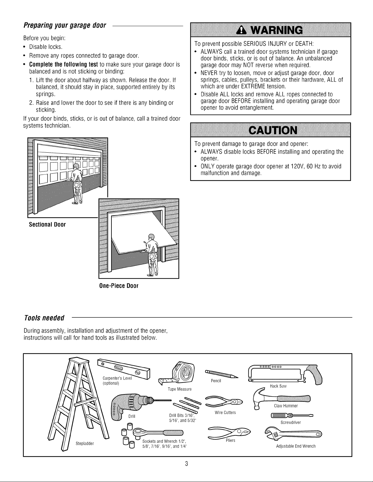
• Completethe followingtest to make sureyour garage door is
balancedand is not sticking or binding:
1. Lift the door about halfwayas shown. Releasethe door. If
balanced,it should stay in place,supported entirelyby its
springs.
2. Raiseand lower the door to see if there is any binding or
sticking.
If your door binds, sticks, or is out of balance,call atrained door
systems technician.
To prevent possible SERIOUSINJURYor DEATH:
• ALWAYScall atrained door systems technician if garage
door binds, sticks, or is out of balance.An unbalanced
garagedoor may NOTreversewhen required.
• NEVERtry to loosen, move or adjust garagedoor, door
springs, cables,pulleys, brackets or their hardware,ALL of
which areunder EXTREMEtension.
• DisableALL locks and removeALL ropes connectedto
garagedoor BEFOREinstalling andoperating garagedoor
opener to avoidentanglement.
To prevent damage to garage door and opener:
• ALWAYSdisable locks BEFOREinstalling and operatingthe
opener.
• ONLYoperate garagedoor openerat 120V, 60 Hzto avoid
malfunction and damage.
Sectional Door
One-Piece Door
Tools needed
During assembly, installation and adjustment of the opener,
instructions will call for hand tools as illustrated below.
(optional)
Tape Measure
Pencil
Hack Saw
Stepladder
Screwdriver
Adjustable EndWrench
Page 4

P_nnmg
Identify the type and height of your garagedoor. Surveyyour
garage areato see if any of the conditions below apply to your
installation. Additional materials may be required. You mayfind it
helpful to refer back to this page andthe accompanying
illustrations asyou proceedwith the installation of your opener.
Dependingon your requirements,there areseveralinstallation
steps which may call for materialsor hardware not included in the
carton.
• Installation Step 1 - Lookat the wall or ceiling abovethe
garagedoor. Theheader bracket must be securelyfastenedto
structural supports.
• Installation Step 5 - Doyou havea finished ceiling in your
garage? If so,a support bracket and additional fastening
hardware may be required.
• Installation Step 12- Dependingupon garageconstruction,
extension brackets or wood blocks may be neededto install
sensors.
• Installation Step 12- Alternatefloor mounting of the safety
reversingsensor will require hardwarenot provided.
Doyou havean access door in addition to the garagedoor? If
not, Model 139.53702 Emergency KeyReleaseis required. See
Accessoriespage.
Lookat the garage door where it meetsthe floor. Any gap
betweenthe floor andthe bottom of the door must not exceed
1/4" (6 mm). Otherwise,the safety reversalsystem may not
work properly. SeeAdjustment Step 2. Floor or door should be
repaired.
SECTIONALDOORINSTALLATIONS
• Doyou havea steel, aluminum, fiberglass or glass panel door?
If so, horizontal andvertical reinforcement is required
(Installation Step8).
• Theopenershould be installed abovethe center of the door. If
there is atorsion spring or centerbearingplate in theway of
the header bracket, it may beinstalled within 4 feet (1.22 m) to
the left or right of the door center.See Installation Steps 1
and 8.
• If your door is more than 7 feet (2.13 m) high, seerail
extension kits listed onAccessories page.
SECTIONALDOORINSTALLATION
Horizontal and vertical reinforcement is
neededfor lightweight garage doors
(fiberglass, steel, aluminum, door with glass
panels, etc.) Seepage 18 for details.
Header Wall
Vertical Centerline
of Garage Door
Gap between floor and bottom
of the door must not exceed
Safety Reversing Sensor
1/4" (6 mm).
Slack in chain tension is
normal when garage door
is closed.
Torsion Spring
Wall-mounted
Door Control
Safety Reversing Sensor
OR
Access Door
Sprin,
0
FINISHEDCEILING
Support bracket
& fastening
hardware is required. See
page 16.
Header CLOSEDPOSITION
Bracket
Trolley Stop Bolt Trolley
Garage Door
Spring
Door
Bracket
Motor Unit
Curved
Door Arm
Chain
Emergency
Release
Rope & Handle
Page 5
Planning(Continued)
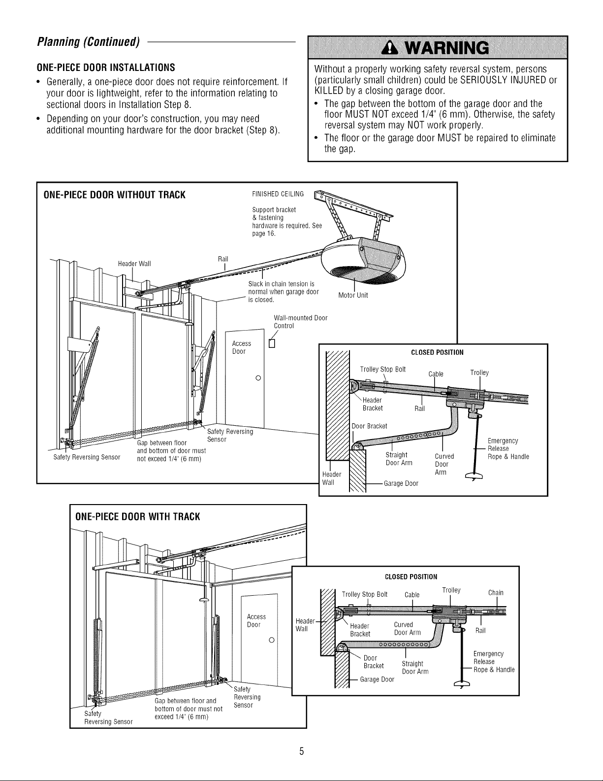
ONE-PIECEDOORINSTALLATIONS
• Generally,a one-piecedoor does not require reinforcement. If
your door is lightweight, refer to the information relatingto
sectional doors in Installation Step 8.
• Dependingon your door's construction, you may need
additional mounting hardware for the door bracket (Step8).
ONE-PIECEDOORWITHOUTTRACK
Rail
Header Wall I
FINISHEDCEILING
Support bracket
& fastening
hardware is required. See
page 16.
Slack in chain tension is
normal when garage door
is closed.
Wall-mounted Door
Without a properly working safety reversal system, persons
(particularly small children) could beSERIOUSLYINJUREDor
KILLEDby a closing garagedoor.
• Thegap betweenthe bottom of the garagedoor andthe
floor MUST NOTexceed1/4" (6 mm). Otherwise,the safety
reversalsystem may NOTwork properly.
• Thefloor or the garage door MUSTbe repairedto eliminate
the gap.
Motor Unit
CLOSEDPOSITION
I and bottom of door must
Safety Reversing Sensor not exceed 1/4" (6 mm)
Gap between floor
Safety Reversing
Sensor
Trolley Stop Bolt
CLOSED POSITION
Trolley Stop Bolt Cable Trolley
e Door
Door
Straight
DoorArm
Cable Trolley
Curved
Door
Arm
Emergency
Release
Rope & Handle
Chain
Rail
Emergency
Release
& Handle
_-°nruass _dnot _!!!sing _ I
Safety
Reversing Sensor J
Gap between floor and ..... I
exceed 1/4" (6 mm)
Reversing
S_HbU/
Page 6
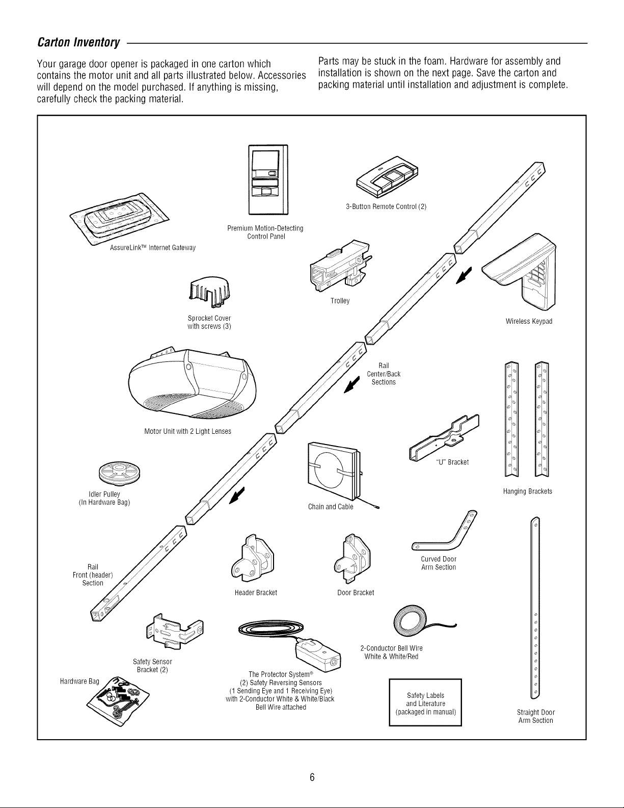
CartonInventory
Your garagedoor openeris packagedin onecarton which
contains the motor unit andall parts illustrated below. Accessories
will depend on the model purchased. If anything is missing,
carefully check the packing material.
Premium Motion-Detecting
Control Panel
AssureLinkTM Internet Gateway
Sprocket Cover
with screws (3)
Parts maybestuck in the foam. Hardwarefor assembly and
installation is shown on the next page.Savethe carton and
packing materialuntil installation and adjustment is complete.
0
3-Button Remote Control (2)
Trolley
Wireless Keypad
(In Hardware Bag)
Front_i_ader)
Hardware_
Idler Pulley
Motor Unit with 2 Light Lenses
Safety Sensor
Bracket (2)
Chain and Cable
Header Bracket
The Protector System®
(2) Safety Reversing Sensors
(1 Sending Eyeand 1 Receiving Eye)
with 2-Conductor White & White/Black
BellWire attached
Center/Back
Door Bracket
2-Conductor BellWire
White & White/Red
Rail
Sections
(packaged in manual)
CurvedDoor
ArmSection
Safety Labels
and Literature
i.
_)1 ,,,
% _l_
Ol
io
I%
I<_
% <
Ol o] c_
Hanging Brackets
Straight Door
Arm Section
Page 7
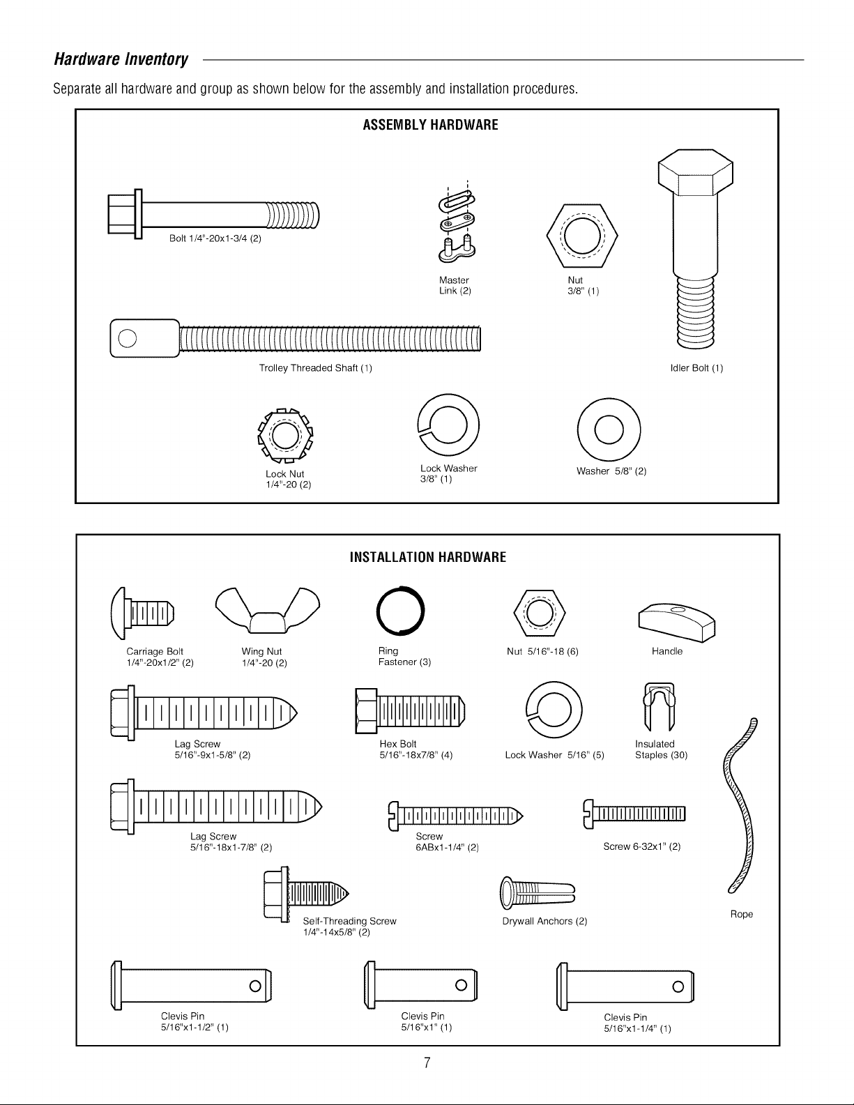
HardwareInventory
Separateall hardwareandgroup as shown below for the assembly andinstallation procedures.
ASSEMBLYHARDWARE
Bolt 1/4"-20xl-3/4 (2)
Master
Link (2)
Trolley Threaded Shaft (1)
Lock Nut 3/8' (1)
1/4"-20 (2)
Lock Washer Washer 5/8' (2)
INSTALLATIONHARDWARE
0
Carriage Bolt Wing Nut Ring Nut 5116"-18 (6)
1/4"-20xl/2" (2) 1/4"-20 (2) Fastener (3)
Nut
3/8' (1)
Idler Bolt (1)
Handle
Lag Screw Hex Bolt
5/16"-9xl-5/8" (2) 5/16"-18x7/8" (4) Lock Washer 5/16" (5)
111111111111_>
Lag Screw
5/16"-18xl -7/8" (2)
Self-Threading Screw
1/4"-14x5/8" (2)
Clevis Pin Clevis Pin
5/16"x1-1/2" (1) 5/16"x1" (1)
_ IMIMl'l'lllllllllllllll'l_
Screw
6ABx1-1/4" (2)
JIH/I J
Drywall Anchors (2)
Insulated
Staples (30)
_ IIIIIIIIIIIIIIIIIIIII
Screw 6-32x1" (2)
Rope
o_
Clevis Pin
5/16"x1-1/4" (1)
Page 8
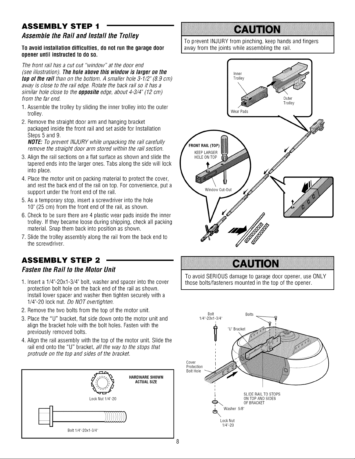
ASSEMBLY STEP 1
Assemblethe Rail andInstal/the Trolley
To avoidinstallation difficulties,do not runthe garagedoor
opener until instructedto doso.
Thefront rail has acut out "window" at the door end
(seeillustration). Theholeabove this windowis larger onthe
top of the raft than on the bottom. Asmaller hole3-1/2" (8.9 cm)
away is close to the rail edge.Rotatethe backrail so it has a
similar hole closeto the oppositeedge,about 4-3/4" (12 cm)
from the far end.
1. Assemble the trolley by sliding the inner trolley into the outer
trolley.
2. Removethe straight door arm and hanging bracket
packagedinside the front rail and set asidefor Installation
Steps 5 and9.
NOTE:Toprevent INJURY while unpacking the rail carefully
remove the straight door arm stored within the rail section.
3. Align the rail sections on a flat surface as shown and slide the
taperedends into the larger ones. Tabs along the sidewill lock
into place.
4. Placethe motor unit on packing material to protect the cover,
and restthe back end of the rail ontop. For convenience,put a
support under the front end of the rail.
5. As atemporary stop, insert a screwdriver into the hole
10"(25cm) from the front end of the rail, as shown.
6. Checkto besure there are4 plastic wear pads insidethe inner
trolley. If they becameloose during shipping, check all packing
material.Snap them back into position as shown.
7. Slide the trolley assemblyalong the rail from the back endto
the screwdriver.
To prevent INJURYfrom pinching, keephandsand fingers
away from the joints while assembling the rail.
Inner
Trolley
Outer
Trolley
Wear Pads
[TOP)
KEEPLARGER
HOLEON TOP
Window Cut-Out
ASSEMBLY STEP 2
Fastenthe Rail tothe MotorUnit
1. Inserta 1/4"-20xl-3/4" bolt, washerand spacerinto the cover
protection bolt hole on the back end of the rail as shown.
Install lower spacerandwasherthen tighten securelywith a
1/4"-20 lock nut. DoNOT overtighten.
2. Removethe two bolts from the top of the motor unit.
3. Placethe "U" bracket,flat side down onto the motor unit and
align the bracketholewith the bolt holes. Fastenwith the
previously removed bolts.
4. Align the rail assemblywith the top of the motor unit. Slidethe
rail end onto the "U" bracket,aft the way to the stops that
protrude on the top andsides of the bracket.
HARDWARESHOWN
ACTUALSIZE
Q
Lock Nut 1/4"-20
Bolt 1/4"-20xl-3/4"
To avoid SERIOUSdamageto garagedoor opener, use ONLY
those bolts/fasteners mounted in the top of the opener.
Bolt Bolts
1/4"-20xl-3/4"
"U" Bracket
Cover
Protection
Bolt Hole
l
l
I SLIDE RAIL TO STOPS
t ONTOP AND SIDES
Washer 5/8"
Lock Nut
1/4"-20
OFBRACKET
Page 9
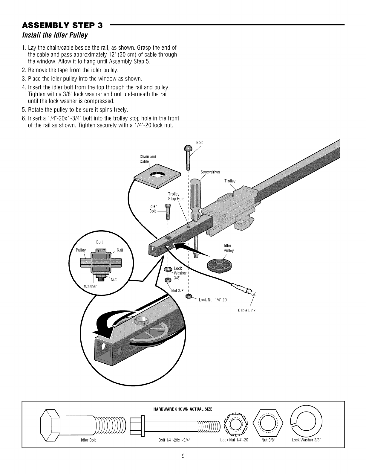
ASSEMBLY STEP 3
Insta// the Id/er Pu//ey
1. Lay the chain/cable besidethe rail, as shown. Graspthe end of
the cable andpassapproximately 12"(30 cm) of cablethrough
the window. Allow it to hanguntil Assembly Step 5.
2. Removethe tape from the idler pulley.
3. Placethe idler pulley into the window asshown.
4. Insert the idler bolt from the top through the rail andpulley.
Tighten with a 3/8" lock washer and nut underneaththe rail
until the lock washer is compressed.
5. Rotatethe pulley to besure it spins freely.
6. Insert a1/4"-20xl-3/4" bolt into the trolley stop hole inthe front
of the rail as shown. Tighten securely with a 1/4"-20 lock nut.
Chain and
Cable
Trolley
Stop Hole
Idler@
Bolt
Screwdriver
Trolley
\
Washer
Bolt
Bolt -_
I
t
Nut 3/8"
Idler
Pulley
3/8"
Lock Nut 1/4"-20
Cable Link
Idler Bolt
HARDWARESHOWN ACTUALSIZE
Bolt 1/4"-20xl-3/4" Lock Nut 1/4"-20 Nut 3/8" Lock Washer 3/8"
Page 10
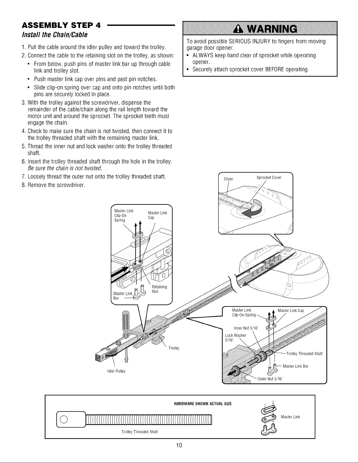
ASSEMBLY STEP 4
Install the Chain/Cable
1. Pull the cablearound the idler pulley andtoward the trolley.
2. Connect the cable to the retaining slot on the trolley, asshown:
• From below,push pins of master link barup through cable
link and trolley slot.
• Pushmaster link cap over pins and past pin notches.
• Slide clip-on spring over capand onto pin notches until both
pins aresecurely lockedin place.
3. With the trolley against the screwdriver, dispensethe
remainderof the cable/chainalong the rail length toward the
motor unit and around the sprocket. Thesprocket teeth must
engagethe chain.
4. Checkto make sure the chain is not twisted, then connect it to
the trolley threadedshaft with the remaining master link.
5. Thread the inner nut and lock washer onto the trolley threaded
shaft.
6. Insertthe trolley threaded shaft through the hole in the trolley.
Besure the chain is not twisted.
7. Looselythread the outer nut onto the trolley threaded shaft.
8. Removethe screwdriver.
To avoid possibleSERIOUSINJURYto fingers from moving
garagedoor opener:
• ALWAYSkeep handclearof sprocket while operating
opener.
• Securely attachsprocket cover BEFOREoperating.
Chain Sprocket Cover
Master Link Master Link
Clip-On Cap
Spring
Idler Pulley
Retaining
Slot
Trolley
Master Link
Clip-On Sprin
Master Link Cap
©
HARDWARESHOWN ACTUALSIZE
Master Link
Trolley Threaded Shaft
10
Page 11
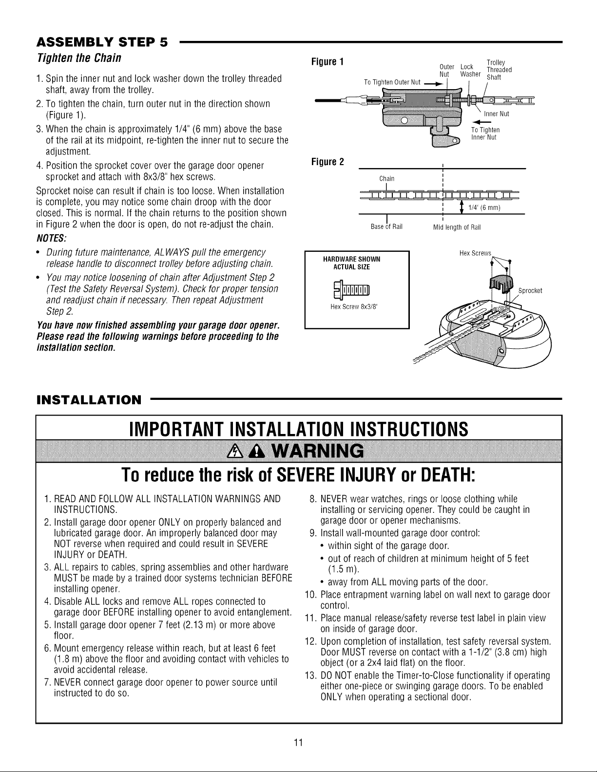
ASSEMBLY STEP 5
Tightenthe Chain
1. Spin the inner nut and lock washer down the trolley threaded
shaft, awayfrom the trolley.
2. To tightenthe chain, turn outer nut in the direction shown
(Figure 1).
3. When the chain is approximately 1/4" (6 mm) above the base
of the rail at its midpoint, re-tighten the inner nut to securethe
adjustment.
4. Position the sprocketcover over the garagedoor opener
sprocket andattachwith 8x3/8" hex screws.
Sprocket noise can result if chain is too loose. When installation
is complete, you may noticesomechain droop with the door
closed.This is normal. If the chain returns to the position shown
in Figure2 whenthe door is open, do not re-adjust the chain.
NOTES:
• During future maintenance,ALWAYSpull the emergency
releasehandle to disconnect trolley before adjusting chain.
• You may notice loosening of chain aflerAdjustment Step 2
(Testthe SafetyReversalSystem). Checkfor proper tension
and readjustchain if necessary. ThenrepeatAdjustment
Step2.
Youhave nowfinished assemblingyourgaragedoor opener.
Please read thefollowingwarningsbeforeproceedingto the
installationsection.
Figure1 Trolley
To Tighten Outer Nut
Figure2
Chain
Base !f Rail
HARDWARESHOWN
ACTUALSIZE
Hex Screw 8x3/8"
Outer Lock Threaded
Nut Washer Shaft
Inner Nut
ToTighten
Inner Nut
I
1/4" (6 mm)
,,
Mid length of Rail
Hex Screws
Sprocket
INSTALLATION
IMPORTANTINSTALLATIONINSTRUCTIONS
ToreducetheriskofSEVEREINJURYorDEATH:
1. READAND FOLLOWALL INSTALLATIONWARNINGSAND
INSTRUCTIONS.
2. Install garagedoor opener ONLYon properly balancedand
lubricated garagedoor. An improperly balanceddoor may
NOT reversewhen required and could result in SEVERE
INJURYor DEATH.
3. ALL repairsto cables,spring assembliesand other hardware
MUST be made by a trained door systems technician BEFORE
installing opener.
4. DisableALL locks and removeALL ropesconnectedto
garagedoor BEFOREinstalling openerto avoid entanglement.
5. Install garagedoor opener 7 feet (2.13 m) or more above
floor.
6. Mount emergency releasewithin reach, but at least 6 feet
(1.8 m) abovethe floor and avoiding contactwith vehicles to
avoid accidental release.
7. NEVERconnect garagedoor openerto power source until
instructed to do so.
8. NEVERwearwatches, rings or looseclothing while
installing or servicing opener. They could be caught in
garage door or openermechanisms.
9. Install wall-mounted garage door control:
• within sight of the garagedoor.
• out of reachof children at minimum height of 5 feet
(1.5 m).
• away from ALL moving parts of the door.
10. Placeentrapment warning labelon wall nextto garage door
control.
11. Placemanual release/safetyreversetest labelin plain view
on inside of garagedoor.
12. Upon completion of installation, test safety reversalsystem.
Door MUST reverseon contactwith a 1-1/2" (3.8 cm) high
object (or a2x4 laid flat) on the floor.
13. DONOTenablethe Timer-to-Close functionality if operating
either one-piece or swinging garagedoors. To beenabled
ONLYwhen operating a sectionaldoor.
11
Page 12
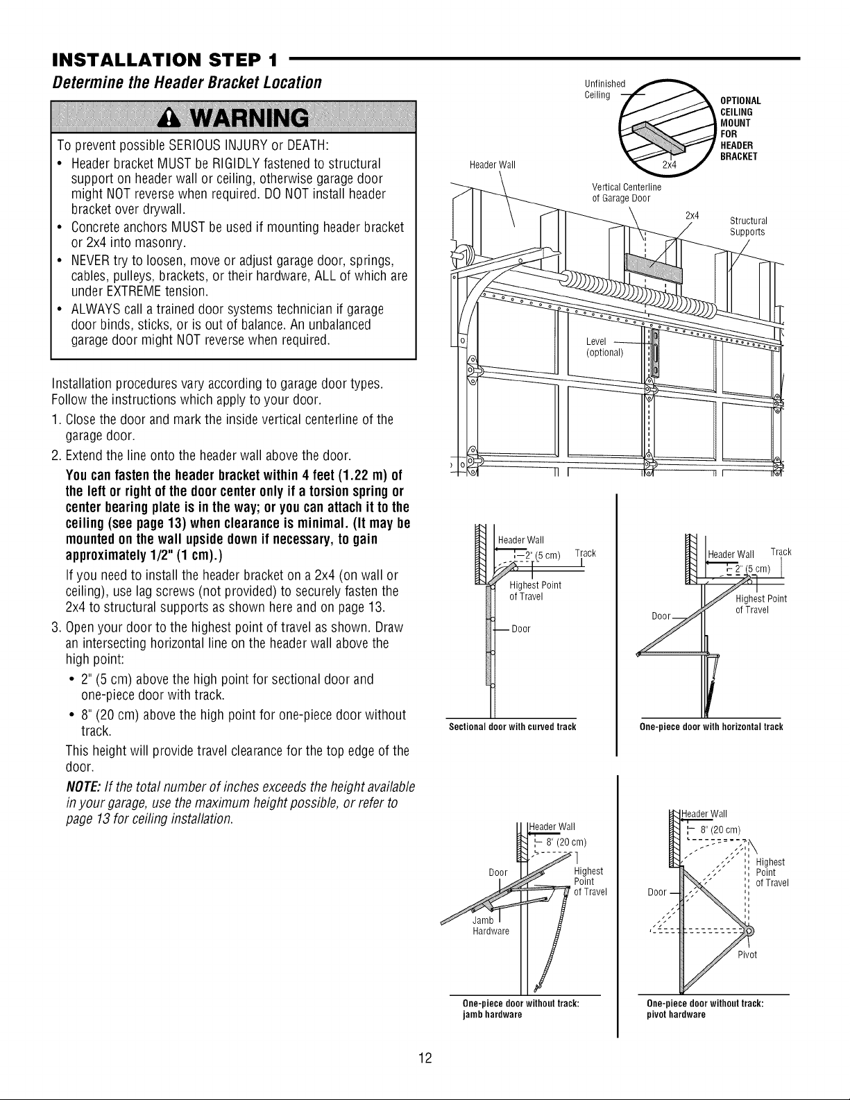
INSTALLATION STEP 1
Determinethe HeaderBracketLocation
Un.f!nished
To prevent possible SERIOUSINJURYor DEATH:
• Headerbracket MUST be RIGIDLYfastenedto structural
support on headerwall or ceiling, otherwise garagedoor
might NOTreversewhen required. DONOTinstall header
bracket over drywall.
• ConcreteanchorsMUSTbe usedif mounting headerbracket
or 2x4 into masonry.
• NEVERtry to loosen, move or adjust garagedoor, springs,
cables, pulleys, brackets, or their hardware,ALL of which are
under EXTREMEtension.
• ALWAYScall a trained door systems technician if garage
door binds, sticks, or is out of balance.Anunbalanced
garagedoor might NOTreversewhen required.
Installation proceduresvary accordingto garagedoor types.
Follow the instructions which applyto your door.
1. Closethe door and mark the insidevertical centerline of the
garagedoor.
2. Extendthe lineonto the headerwall abovethe door.
Youcanfasten the header bracketwithin 4 feet(1.22 m) of
the left or rightof thedoorcenteronly if a torsion springor
center bearingplate is inthe way; or youcanattach itto the
ceiling (see page 13) whenclearanceis minimal. (It may be
mountedon thewall upsidedown if necessary,to gain
approximately1/2" (1 cm).)
If you needto install the headerbracket on a 2x4 (on wall or
ceiling), use lag screws (not provided) to securelyfasten the
2x4 to structural supports as shown hereand on page13.
3. Openyour door to the highest point of travel asshown. Draw
an intersectinghorizontal lineon the headerwall abovethe
high point:
• 2" (5 cm) abovethe high point for sectionaldoor and
one-piecedoor with track.
• 8" (20 cm) abovethe high point for one-piecedoor without
track.
This heightwill provide travel clearancefor the top edgeof the
door.
NOTE:If the totalnumber of inches exceedsthe heightavailable
in your garage,use themaximum height possible, or refer to
page 13for ceiling installation.
Header Wall
HeaderWall
"_[_",--2"(5 cm) Track
Highest Point
of Travel
--Door
Sectional door with curved track
Header Wall
',- 8" (20 cm)
Door
Ceiling _ BRACKETMOUNTCEILINGOPTIONALHEADERFOR
Vertical Centerline
of Garage Door
2x4
Structural
Supports
HeaderWall Track
HighestPoint
of Travel
T
One-piece door with horizontaltrack
-leader Wall
8" (20 cm)
Highest
Point
of Travel
Highest
Point
of Travel
12
Hardware
One-piecedoorwithouttrack:
jambhardware
Pivot
One-piece door without track:
pivot hardware
Page 13
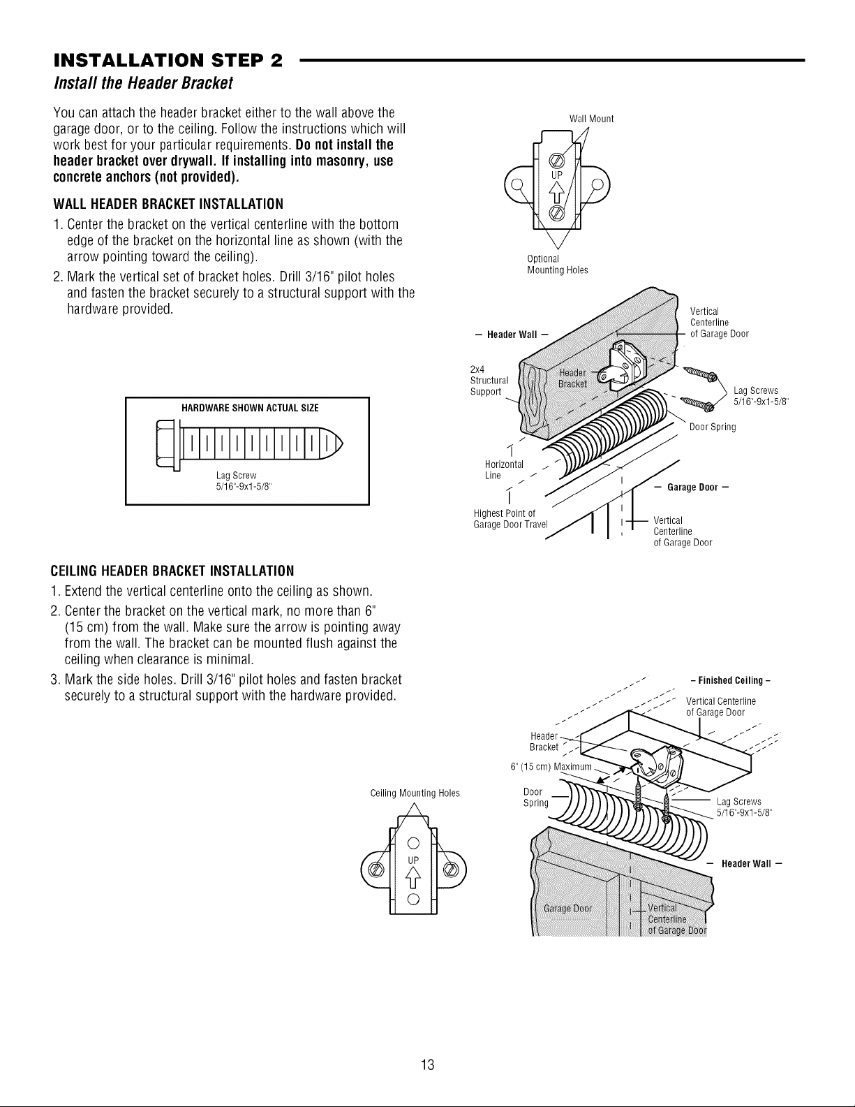
INSTALLATION STEP 2
Install the HeaderBracket
You can attach the headerbracketeither to the wall abovethe
garagedoor, or to the ceiling. Followthe instructions which will
work bestfor your particular requirements. Do notinstall the
headerbracketoverdrywall. If installinginto masonry,use
concreteanchors(notprovided).
WALLHEADERBRACKETINSTALLATION
1. Centerthe bracket on the vertical centerlinewith the bottom
edge of the bracket on the horizontal line asshown (with the
arrow pointing toward the ceiling).
2. Mark the vertical set of bracket holes.Drill 3/16" pilot holes
and fastenthe bracketsecurely to a structural support with the
hardware provided.
HARDWARESHOWN ACTUALSIZE
lllllllllll
LagScrew
5/16"-9xl -5/8"
Optional
Mounting Holes
- Header Wall -
2x4
Structural
SuppoR
7
1
Horizontal
Line
i
HighestPoint of
GarageDoorTravel
Wall Mount
Vertical
Centerline
of GarageDoor
_ Lag Screws
Door Spring
- Garage Door -
Vertical
Centerline
of GarageDoor
5/16"-9xl-5/8"
CEILINGHEADERBRACKETINSTALLATION
1. Extendthe vertical centerline onto the ceiling as shown.
2. Centerthe bracketon the vertical mark, no more than 6"
(15 cm) from the wall. Makesure the arrow is pointing away
from the wall. The bracket can be mounted flush against the
ceiling when clearanceis minimal.
3. Mark the side holes. Drill 3/16" pilot holes and fasten bracket
securelyto a structural support with the hardwareprovided.
Ceiling Mounting Holes
6"(15cm) M a num._.
Door
Spring
-- Lag Screws
5/16"-9xl -5/8"
Header Wall -
13
Page 14

INSTALLATION STEP 3
AttachtheRail to the HeaderBracket
1. Position the openeron the garagefloor below the header
bracket. Usepackingmaterial asa protectivebase.NOTE:If the
door spring is in the wayyou'll needhelp. Havesomeone hold
theopener securely ona temporary support to allow the raftto
clearthe spring.
2. Position the rail bracket againstthe headerbracket.
3. Align the bracket holesand join with a clevis pin 5/16"x1-1/2"
as shown.
4. Inserta ring fastener to secure.
HeaderWall
HeaderBracket
Idler Pulley
__ Garage
Door
Header
Bracket
Mounting
Hole
0
i
\
__ Temporary
Opener Carton or
Support
HARDWARESHOWN ACTUALSIZE
o]
Clevis Pin 5/16"x1-1/2"
14
0
Ring Fastener
Page 15
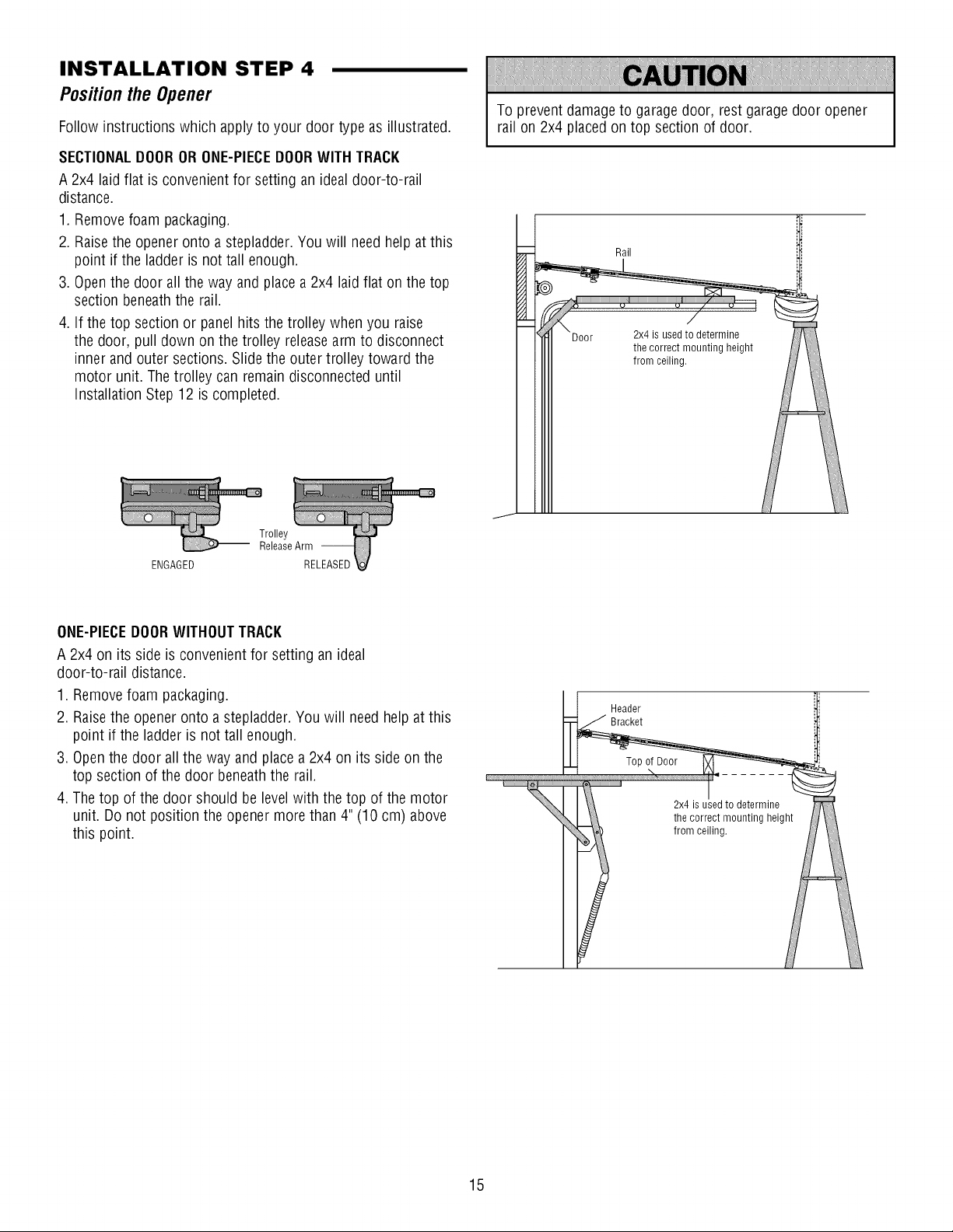
INSTALLATION STEP 4
PositiontheOpener
Follow instructions which apply to your door type as illustrated.
SECTIONALDOORORONE-PIECEDOORWITH TRACK
A 2x4 laid flat is convenientfor setting an ideal door-to-rail
distance.
1. Removefoam packaging.
2. Raisethe openeronto a stepladder.You will needhelp at this
point if the ladder is not tall enough.
3. Openthe door allthe way andplace a 2x4 laid flat on the top
section beneaththe rail.
4. If the top section or panel hits the trolley when you raise
the door, pull down on the trolley releasearm to disconnect
inner and outer sections. Slidethe outer trolley toward the
motor unit. Thetrolley can remain disconnecteduntil
Installation Step12 is completed.
To prevent damageto garage door, rest garage door opener
rail on 2x4 placedon top section of door.
Rail
ENGAGED
ONE-PIECEDOORWITHOUTTRACK
A 2x4 on its side is convenient for setting an ideal
door-to-rail distance.
1. Removefoam packaging.
2. Raisethe openeronto a stepladder.You will need help at this
point if the ladder is not tall enough.
3. Openthe door all the way andplace a 2x4 on its side on the
top section of the door beneaththe rail.
4. The top of the door should be levelwith the top of the motor
unit. Do not position the opener morethan 4" (10 cm) above
this point.
Header
Bracket
2x4 is usedto determine
the correct mounting height
from ceiling.
i
15
Page 16
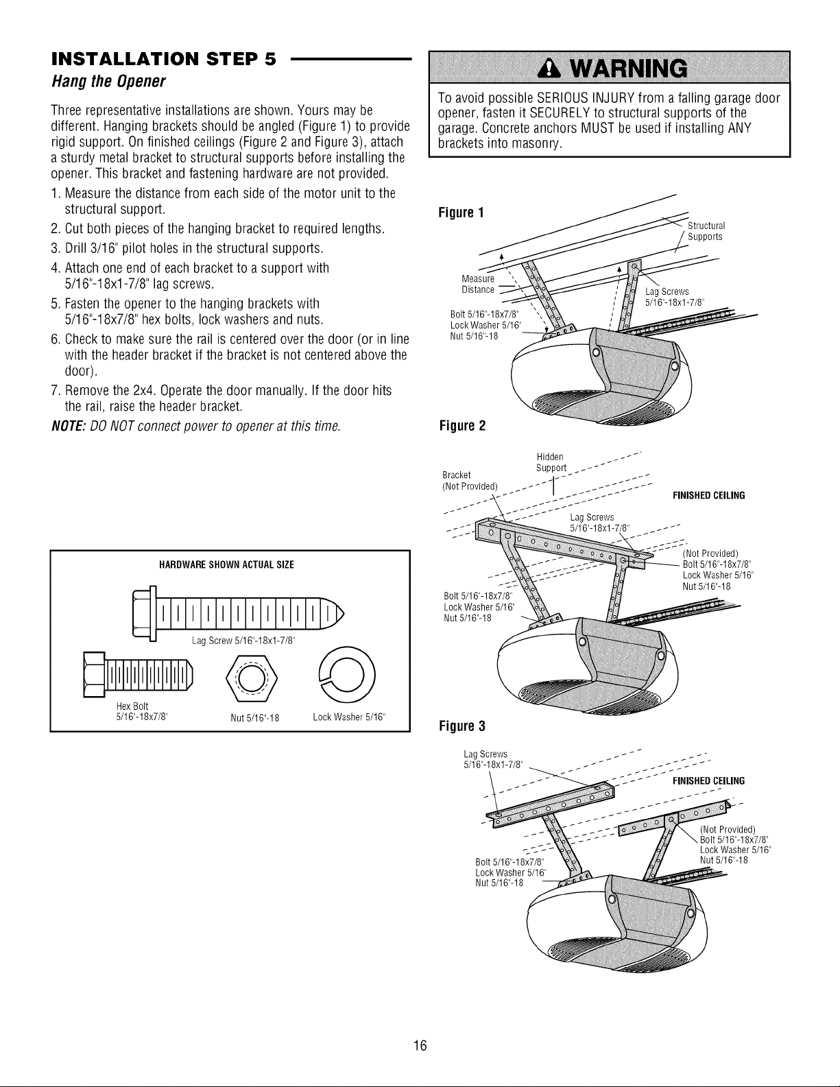
INSTALLATION STEP 5
Hangthe Opener
Threerepresentativeinstallations are shown. Yours may be
different. Hangingbrackets should beangled (Figure 1) to provide
rigid support. Onfinished ceilings (Figure2 and Figure3), attach
a sturdy metal bracket to structural supports before installingthe
opener.This bracketand fastening hardwareare not provided.
1. Measurethe distancefrom eachside of the motor unit to the
structural support.
2. Cut both piecesof the hanging bracket to required lengths.
3. Drill 3/16" pilot holes inthe structural supports.
4. Attach oneendof eachbracket to a support with
5/16"-18xl -7/8" lagscrews.
5. Fastenthe opener to the hanging brackets with
5/16"-18x7/8" hex bolts, lock washers and nuts.
6. Checkto make sure the railis centered over the door (or in line
with the headerbracket if the bracket is not centeredabovethe
door).
7. Removethe 2x4. Operatethe door manually. If the door hits
the rail, raisethe headerbracket.
NOTE:DO NOTconnectpower to openerat this time.
To avoid possibleSERIOUSINJURYfrom a falling garagedoor
opener,fasten it SECURELYto structural supports of the
garage.Concrete anchorsMUSTbe usedif installing ANY
brackets into masonry.
Figure1
Supports
Measure ',
Distance
Bolt 5/16"-18x7/8"
Lock Washer 5/16"
Nut 5/16"-18
Lag Screws
5/16"-18xl -7/8"
Figure2
HARDWARESHOWN ACTUALSIZE
>
HexBolt
5/16"-18x7/8" Nut 5/16"-18 LockWasher 5/16"
Bolt 5/16"-18x7/8"
Lock Washer 5/16"
Nut 5/16"-18
Figure3
LagScrews
5/16"-18xl -7/8"
Bolt 5/16"-18x7/8"
Lock Washer 5/16"
Nut 5/16"-18
Lag Screws
5/16"-18xl -7/8" _ _ _ _ _ _-
FINISHEDCEILING
(Not Provided)
Bolt 5/16"-18x7/8"
Lock Washer 5/16"
Nut 5/16"-18
(Not Provided)
Bolt 5/16"-18x7/8"
Lock Washer 5/16"
Nut 5/16"-18
16
Page 17
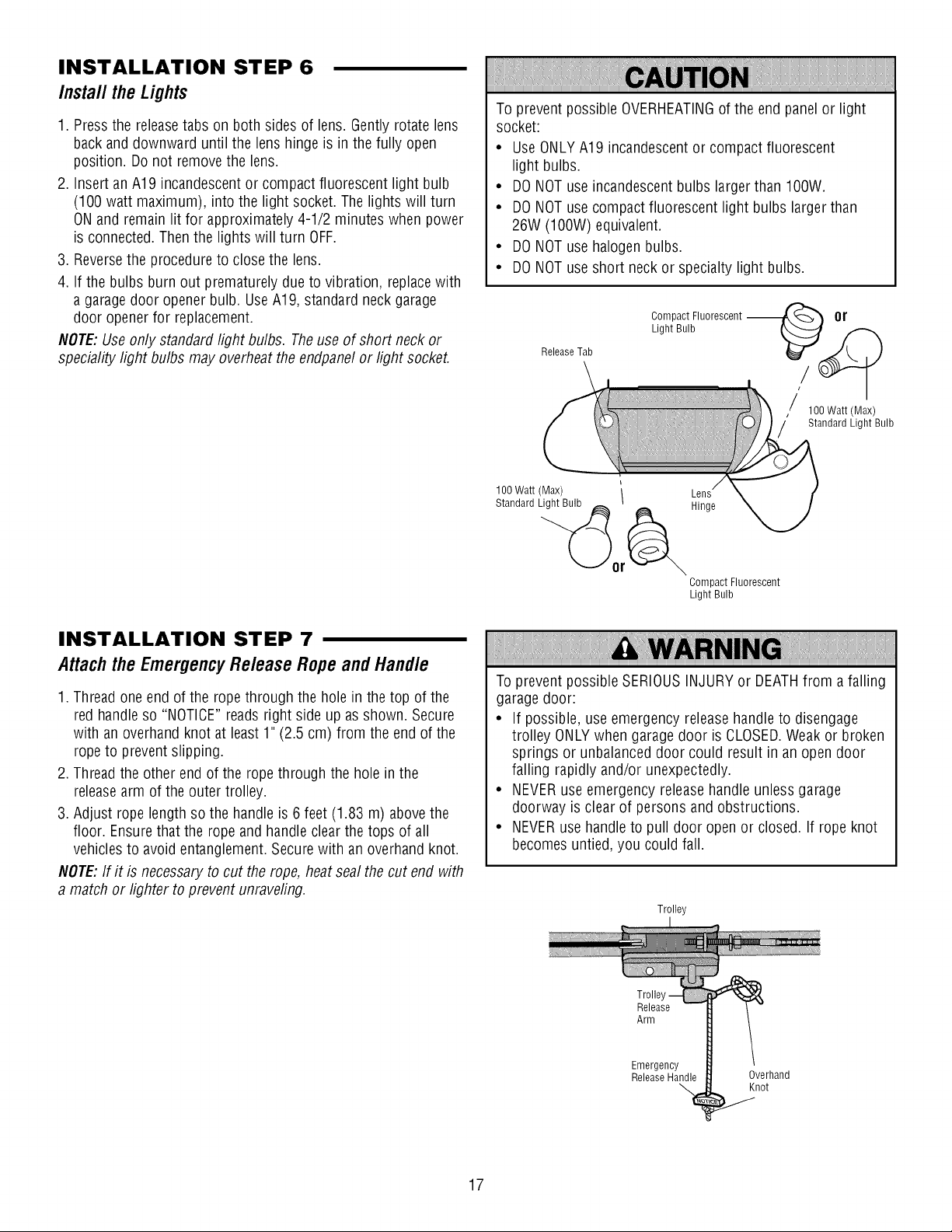
INSTALLATION STEP 6
Install theLights
1. Pressthe releasetabs on both sides of lens. Gentlyrotate lens
back and downward until the lens hinge is in thefully open
position. Do not removethe lens.
2. InsertanA19 incandescentor compact fluorescent light bulb
(100 watt maximum), into the light socket. Thelights will turn
ONand remainlit for approximately 4-1/2 minutes when power
is connected. Then the lights will turn OFF.
3. Reversethe procedureto close the lens.
4. If the bulbs burn out prematurelydue to vibration, replacewith
a garage door openerbulb. UseA19, standard neck garage
door openerfor replacement.
NOTE:Useonly standardlight bulbs. Theuse of short neck or
speciality light bulbs may overheatthe endpanelor light socket.
To prevent possible OVERHEATINGof the end panel or light
socket:
• UseONLYA19 incandescentor compact fluorescent
light bulbs.
• DONOTuse incandescentbulbs larger than 100W.
• DONOTuse compactfluorescent light bulbs larger than
26W (100W) equivalent.
• DONOTuse halogenbulbs.
• DONOTuse short neckor specialty light bulbs.
Compact Fluorescent --
Light Bulb
ReleaseTab
or
100Watt(Max)
Standard Light Bulb
INSTALLATION STEP 7
Attach the Emergency Release Rope and Handle
1. Thread one end of the ropethrough the hole in the top of the
red handleso "NOTICE"readsright side up asshown. Secure
with an overhandknot at least 1" (2.5 cm) from the endof the
ropeto prevent slipping.
2. Thread the other endof the rope through the hole in the
releasearm of the outer trolley.
3. Adjust rope lengthso the handle is 6 feet (1.83 m) abovethe
floor. Ensurethat the rope and handle clear the tops of all
vehiclesto avoid entanglement.Securewith an overhand knot.
NOTE:If it is necessary to cut the rope, heat seal the cut end with
a match or lighter to preventunraveling.
100 Watt (Max) \
Standard Light Bulb _
/
Hinge
Compact Fluorescent
Light Bulb
Toprevent possible SERIOUSINJURYor DEATHfrom a falling
garage door:
• If possible, use emergency releasehandle to disengage
trolley ONLYwhen garagedoor is CLOSED.Weak or broken
springs or unbalanceddoor could result in an open door
falling rapidly and/or unexpectedly.
• NEVERuse emergency release handle unless garage
doorway is clear of persons andobstructions.
• NEVERusehandle to pull door openor closed. If rope knot
becomesuntied, you could fall.
Trolley
17
Trolle
Release
Arm
Emergency
ReleaseHandle
Overhand
Knot
Page 18
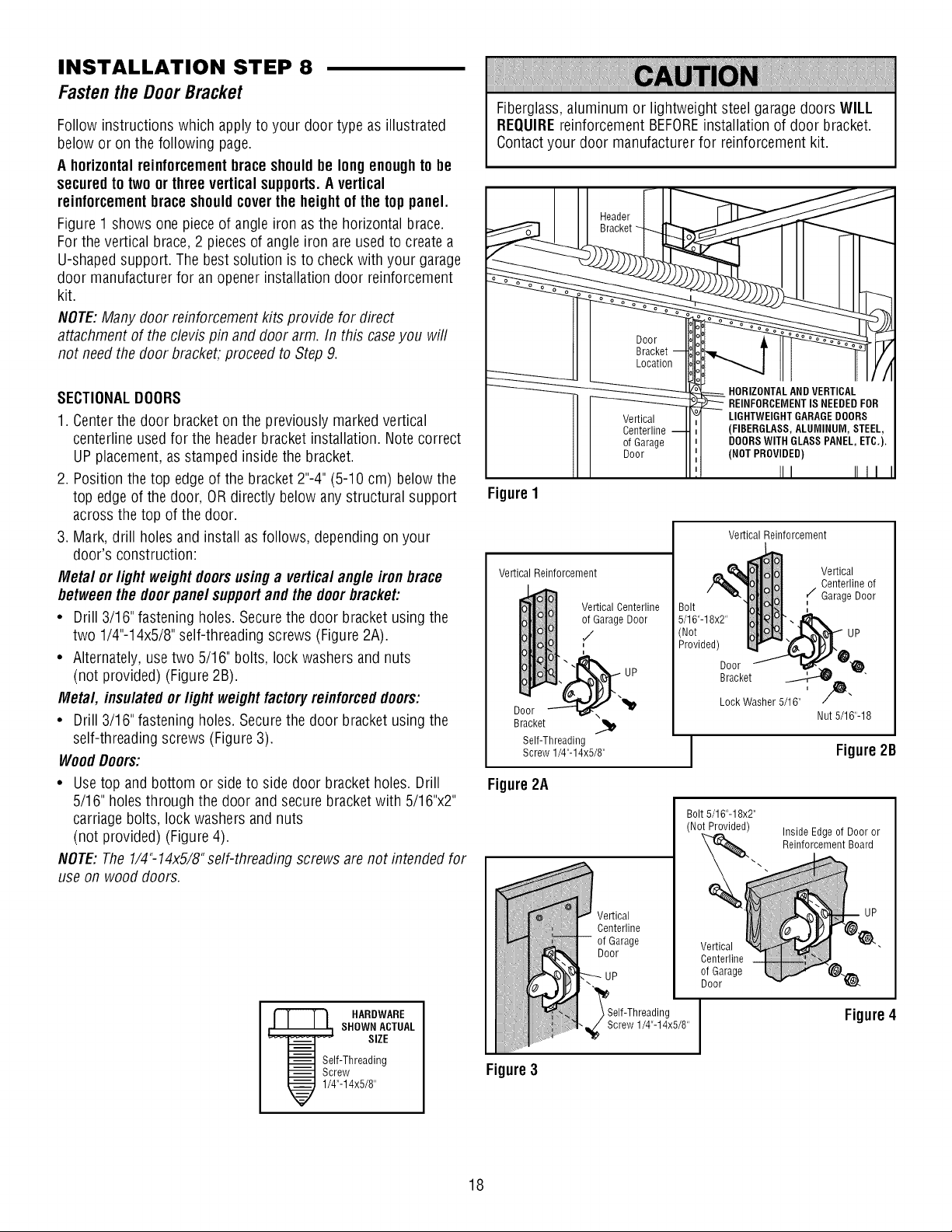
INSTALLATION STEP 8
Fastenthe DoorBracket
Follow instructions which applyto your door type as illustrated
below or on the following page.
A horizontal reinforcementbrace shouldbe longenoughtobe
securedto two or three vertical supports.Avertical
reinforcementbrace shouldcoverthe height of the top panel.
Figure1 shows onepiece of angle iron asthe horizontal brace.
Forthe vertical brace,2 piecesof angle iron are used to createa
U-shapedsupport. The bestsolution is to checkwith your garage
door manufacturerfor an opener installation door reinforcement
kit.
NOTE:Many doorreinforcement kits provide for direct
attachment of the clevis pin and door arm. In this caseyou will
not needthe door bracket, proceed to Step9.
SECTIONALDOORS
1. Centerthe door bracket on the previously markedvertical
centerline usedfor the header bracket installation. Note correct
UPplacement, as stamped insidethe bracket.
2. Position thetop edge of the bracket2"-4" (5-10 cm) below the
top edge of the door, OR directly below anystructural support
acrossthe top of the door.
3. Mark, drill holes andinstall asfollows, depending on your
door's construction:
Metal or light weight doorsusinga vertical angle iron brace
betweenthe doorpanel supportandthe doorbracket:
• Drill 3/16"fastening holes. Securethe door bracket using the
two 1/4"-14x5/8"self-threading screws (Figure2A).
• Alternately, usetwo 5/16" bolts, lock washers andnuts
(not provided) (Figure 2B).
Metal, insulated orlight weight factoryreinforceddoors:
• Drill 3/16"fastening holes. Securethe door bracket using the
self-threading screws (Figure3).
WoodDoors:
• Usetop and bottom or side to side door bracketholes. Drill
5/16" holesthrough the door and secure bracketwith 5/16"x2"
carriagebolts, lock washersand nuts
(not provided) (Figure 4).
NOTE:The1/4"-14x5/8"self-threading screws arenot intended for
use on wood doors.
Fiberglass,aluminum or lightweight steel garagedoors WILL
REQUIREreinforcement BEFOREinstallation of door bracket.
Contactyour door manufacturer for reinforcement kit.
Vertical
Centerline
o1Garage
Door
FigureI
Vertical Reinforcement
Vertical Reinforcement
Vertical Centerline
,,_Garage Door
Door "-'-'-n_'x _1_
Bracket
Self-Threading
Screw 1/4"-14x5/8"
UP
Bolt
5/16"-18x2"
Not
Provided)
Door
Bracket
Lock Washer 5/16"
Vertical
Centerline of
r/Garage Door
Nut 5/16"-18
Figure2B
Figure2A
Bolt5/16"-18x2"
(NotProvided)
Inside Edgeo1Door or
Reinforcement Board
HARDWARE
SHOWN ACTUAL
SIZE
Self-Threading
Screw
1/4"-14x5/8"
Figure3
18
Vertical
Centerline
o1Garage
Door
\
'_Self-Threading
_j_ Screw 1/4"-14x5/8"
Vertical
Centerline
of Garage
Door
Figure4
Page 19
Fasten the Door Bracket (Continued)
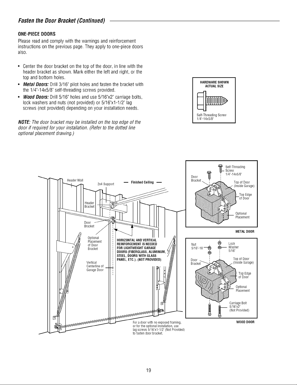
ONE-PIECEDOORS
Pleasereadand comply with the warnings and reinforcement
instructions on the previous page.Theyapplyto one-piece doors
also.
• Centerthe door bracketon thetop of the door, in line with the
header bracketas shown. Mark eitherthe left andright, or the
top and bottom holes.
• Metal Doors:Drill 3/16" pilot holes and fasten the bracketwith
the 1/4"-14x5/8" self-threading screws provided.
• WoodDoors:Drill 5/16" holesand use5/16"x2" carriage bolts,
lock washersand nuts (not provided) or 5/16"x1-1/2" lag
screws (not provided) depending on your installation needs.
NOTE:Thedoor bracket maybe installed on the top edgeof the
door if required for your installation. (Referto the dotted line
optional placementdrawing.)
HARDWARESHOWN
ACTUALSIZE
Self-ThreadingScrew
1/4"-14x5/8"
Header Wall
Door
Bracket
Optional
Placement
of Door
Bracket
Vertical
Centerline of
Garage Door
2x4 Support
m Finished Ceiling --
HORIZONTALANDVERTICAL
REINFORCEMENTISNEEDED
FOR LIGHTWEIGHTGARAGE
DOORS(FIBERGLASS,ALUMINUM,
STEEL, DOORSWITH GLASS
PANEL,ETC.). (NOT PROVIDED)
Door
Bracket_
Screw
'__Self-Threading
' 1/4"-14x5/8"
.............._J!!iii!iii}_
_ Washer
, 5/16"
i
_. arriage Bolt
METAL DOOR
Lock
Top of Door
Top Edge
of Door
Optional
Placement
(Not Provided)
5/16"x2"
Garage)
Fora door with no exposed framing,
or for the optional installation, use
lagscrews 5/16"x1-1/2" (Not Provided)
to fasten door bracket.
19
WOOD DOOR
Page 20

INSTALLATION STEP 9
ConnectDoorArm to Trolley
Follow instructions which apply to your door type asillustrated
below and on the following page.
SECTIONALDOORSONLY
Makesure garage door is fully closed. Pullthe emergency release
handleto disconnect the outer trolley from the inner trolley. Slide
the outer trolley back(awayfrom the pulley) about 8" (20 cm) as
shown in Figures1, 2 and 3.
1. Fastenstraight door arm section to outer trolley with the
5/16"x1"clevis pin. Secure the connection with a ring fastener
(Figure1).
2. Fastencurvedsection to the door bracket in the same way,
using the 5/16"x1-1/4"clevis pin.
IMPORTANT:Thegroove on the straight door arm MUSTface
away from the curved door arm (Figure4).
3. Bring arm sections together. Findtwo pairs of holesthat line up
andjoin sections. Select holesas far apart as possible to
increasedoor arm rigidity (Figure2).
Holealignment alternative (Figure3):
• If holes in curved arm are above holesin straight arm,
disconnect straight arm. Cut about 6" (15 cm) from the solid
end. Reconnectto trolley with cut end down as shown.
• Bring arm sections together.
• Findtwo pairs of holesthat line up and join with bolts, lock
washers and nuts.
Pull the emergency releasehandletoward the opener ata 45°
angle so that the trolley releasearm is horizontal. Trolley will
re-engageautomaticallywhen opener is operatedduring the
adjustments.
Figure1
Figure2
Figure3
Trolley Stop
Bolt
Pulley
Zoor
Clevis Pin
5/16"x1-1/4"
Door
Bracket
Ring
Fastener
Bracket
cm) mm.
Curved
Door Arm
, Bolts
5/16"-18x7/8"
Outer
Trolley
Clevis Pin
5/16"xl"
Emergency
StraightDoor
Arm
Handle
HARDWARESHOWN ACTUALSIZE
Nut 5/16"-18 Lock Washer 5/16" Ring Fastener
Clevis Pin Clevis Pin
5/16"x1" (Trolley) 5/16"x1-1/4" (Door Bracket)
on
Hex Bolt
5/16"-18x7/8"
Figure4
2O
(
DoorArm
(Groove
CORRECT
_Bolts
5/16"-18x7/8"
Cut this end
INCORRECT
Page 21

Connect Door Arm to Tro//ey (Continued)
ALL0NE-PIECEDOORS
IMPORTANT."Thegroove on the straight door arm MUSTface
away from the curved door arm (Figure 5).
1. Closethe door. Disconnectthe trolley by pulling the emergency
releasehandle.
2. Fastenthe straight door arm and the curved door arm together
to the longest possible length (with a 2 or 3hole overlap).
3. Attach the straight door arm to the door bracket using the
5/16"x1-1/4" clevis pin. Securewith the ring fastener.
4. Attach the curved door arm to the trolley using the 5/16"x1"
clevis pin. Securewith the ring fastener.
5. Pull the emergencyreleasehandletoward the garagedoor
opener until the trolley release arm is horizontal.
Trolley Stop
Pulley Trolley
Bolt Inner
Figure5
Outer
Trolley
CORRECT
INCORRECT
Ring
Fastener
StraightDoor
Door
Bracket
Arm
i
Curved
Door Arm
Clevis Pin
5/16"x1-1/4"
INSTALLATION STEP 10
Attachthe WarningLabels
1.Attach the entrapment warning labelon the wall nearthe door
control with tacks or staples.
2. Attach the manual release/safetyreversetest label in a visible
location on the inside of the garagedoor.
Bolts
5/16"-18x7/8"
Clevis Pin
5/16"xl"
Emergency
ReleaseHandle
21
Page 22
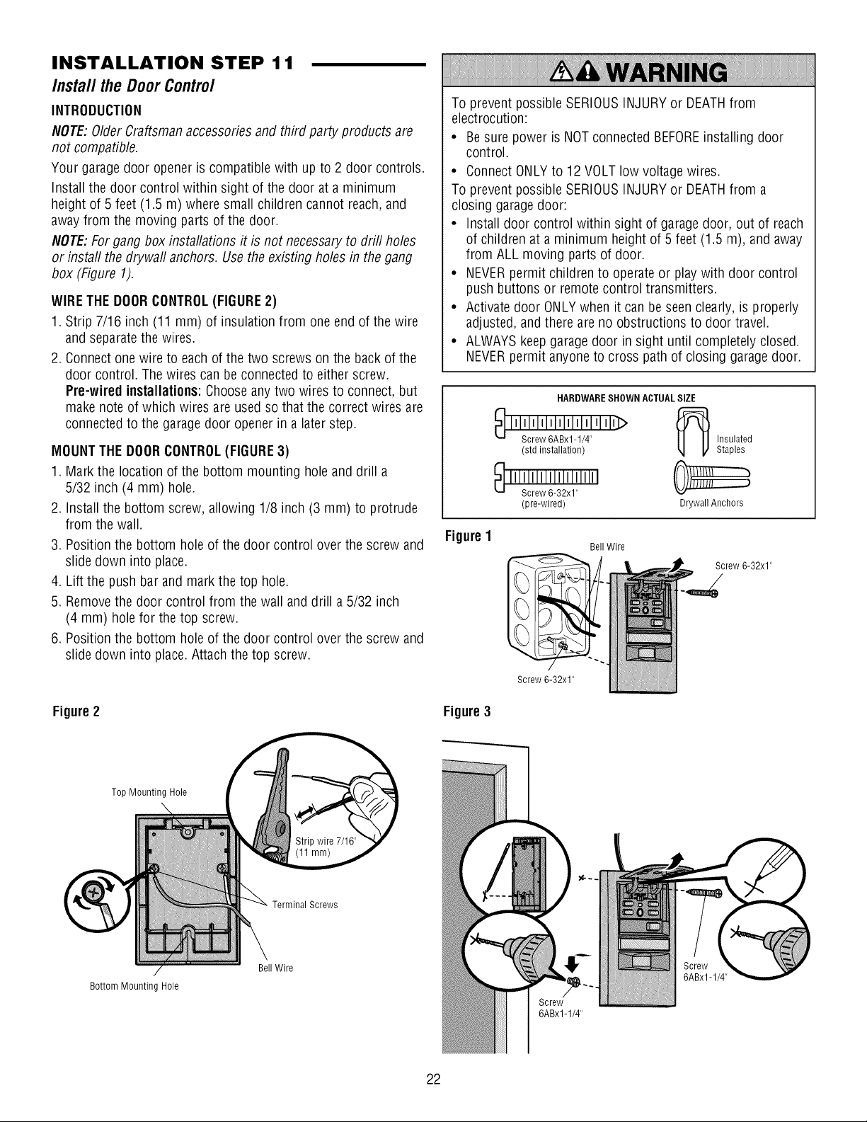
INSTALLATION STEP 11
Install theDoorControl
INTRODUCTION
NOTE:OlderCraftsmanaccessoriesand third party products are
not compatible.
Your garagedoor openeris compatiblewith up to 2 door controls.
Install the door control within sight of the door ata minimum
height of 5 feet (1.5 m) where small children cannot reach,and
away from the moving partsof the door.
NOTE:Forgang box installations it is not necessaryto drill holes
or instafl the drywafl anchors. Usethe existing holes in the gang
box (Figure 1).
WIRETHE DOORCONTROL(FIGURE2)
1. Strip 7/16 inch (11 mm) of insulation from one end of the wire
and separatethe wires.
2. Connect one wire to eachof the two screws on the back of the
door control. Thewires can beconnected to either screw.
Pre-wired installations:Chooseanytwo wires to connect, but
make note of which wires are usedso that the correct wires are
connectedto the garagedoor opener in a laterstep.
MOUNTTHEDOORCONTROL(FIGURE3)
1. Mark the location of the bottom mounting hole and drill a
5/32 inch (4 mm) hole.
2. Installthe bottom screw, allowing 1/8 inch (3 mm) to protrude
from the wall.
3. Position the bottom holeof the door control over the screw and
slide down into place.
4. Lift the push barand markthe top hole.
5. Removethe door control from the wall and drill a 5/32 inch
(4 mm) hole for the top screw.
6. Position the bottom holeof the door control over the screw and
slide down into place. Attach the top screw.
To prevent possible SERIOUSINJURYor DEATHfrom
electrocution:
• Be sure power is NOTconnected BEFOREinstalling door
control.
• ConnectONLYto 12 VOLTlow voltage wires.
To prevent possible SERIOUSINJURYor DEATHfrom a
closing garagedoor:
• Install door control within sight of garage door, out of reach
of children at a minimum height of 5 feet(1.5 m), and away
from ALL moving parts of door.
• NEVERpermit children to operate or playwith door control
push buttons or remotecontrol transmitters.
• Activate door ONLYwhen it can be seenclearly, is properly
adjusted,and there areno obstructions to door travel.
• ALWAYSkeep garage door in sight until completely closed.
NEVERpermit anyoneto cross path of closing garage door.
HARDWARESHOWN ACTUALSIZE
Insulated
Staples
Drywall Anchors
Screw 6-32x1"
Figure1
(std installation)
(pre-wired)
Bell Wire
Screw 6-32x1"
Figure2
Bottom Mounting Hole
Top Mounting Hole
TerminalScrews
Bell Wire
Figure3
6ABx1-1/4"
Screw
6ABx1-1/4"
22
Page 23

Install the Door Contro/ (Continued)
WIRETHE DOORCONTROLTOTHEGARAGEDOOROPENER
(FIGURE4)
Pre-wired installations:When wiring the door control to the
garage door opener makesure you use the same wires that are
connectedto the door control.
1. Runthe white and red/white wire from the door control to the
garagedoor opener. Attachthe wire to the wall and ceiling with
the staples (not applicablefor gang box or pre-wired
installations). Do not piercethe wire with the staple asthis may
cause a short or anopen circuit.
2. Strip 7/16 inch (11 mm) of insulation from the other end of the
wire nearthe garagedoor opener.
3. Connect the wire to the red and white terminals on the garage
door opener.
INSTALLATION STEP 12
Install TheProtectorSystem®
IMPORTANTINFORMATIONABOUTTHESAFETYREVERSING
SENSOR
The safetyreversingsensormustbeconnectedandaligned
correctlybeforethe garagedooropenerwill move in the down
direction.
Thesending sensor (with an amber LED)transmits an invisible
light beamto the receiving sensor (with a green LED). If an
obstruction breaksthe light beam while the door is closing, the
door will stop and reverseto the full open position, and the
garage door opener lights will flash 10times.
NOTE:For energyefficiency thegarage door opener will enter
sleepmode whenthe dooris fully closed. Thesleepmode shuts
the garagedoor opener down until activated. Thesleepmodeis
sequenced with the garagedoor opener light bulb; as the light bulb
turns off the sensor LEDs will turn off and wheneverthegarage
door openerlights turn onthe sensor LEDs will light. Thegarage
door opener will not go into the sleep mode until the garagedoor
opener has completed 5 cyclesuponpower up.
Figure4 DoorControlConnections
Strip wire 7/16" (11 mm)
o release or insert wire, push
in tab with screwdriver tip
Besure power is NOTconnectedto the garagedoor opener
BEFOREinstalling the safety reversing sensor.
To prevent SERIOUSINJURYor DEATHfrom a closing garage
door:
• Correctly connect andalign the safety reversingsensor. This
required safety device MUSTNOTbe disabled.
• Install the safetyreversingsensorso beamis NOHIGHER
than 6" (15 cm) abovegaragefloor.
When installing the safetyreversing sensors checkthe following:
• Sensors are installed insidethe garage,one on either side of
the door.
• Sensors are facing eachother with the lensesaligned and the
receivingsensor lensdoes not receivedirect sunlight.
• Sensors are no more than 6 inches(15 cm) above the floor and
the light beam is unobstructed.
Safety Reversing Sensor
6" (15 cm) max. above floor
Facingthe doorfrom insidethegarage
Invisible Light
Beam Protection
Area
Safety Reversing Sensor
6" (15 cm) max. above floor
23
Page 24

Instal/The ProtectorSystem®(Continued)
INSTALLINGTHE BRACKETS
Besure powerto the opener is disconnected.Installandalign
the brackets so the sensorswill face eachother across the
garagedoor, with the beam no higher than 6" (15 cm) abovethe
floor. Theymay beinstalled in one of three ways, asfollows.
Garage doortrackinstallation (preferred):
• Slip the curved arms overthe rounded edge of each door
track, with the curved arms facingthe door. Snap into place
against the side of the track. It should lie flush, with the lip
hugging the back edgeof the track, asshown in Figure 1.
If your door track will not support the bracket securely, wall
installation is recommended.
Waftinstallation (Figures2 & 3):
• Placethe bracketagainst the wall with curved arms facing the
door. Besure there is enough clearancefor the sensor beam
to be unobstructed.
• If additional depth is needed,an extension bracket (see
Accessories) or wood blocks can be used.
• Use bracketmounting holesas a template to locate and drill
(2) 3/16" diameter pilot holeson the wall at eachside of the
door, no higher than 6" (15 cm) abovethe floor.
• Attach bracketsto wall with lag screws (not provided).
• If using extensionbrackets or wood blocks, adjust right and
left assembliesto the same distance out from the mounting
surface. Make sure all door hardware obstructions are cleared.
Floorinstallation (Figure4):
• Usewood blocks or extension brackets(seeAccessories)to
elevatesensor bracketsso the lenseswill be no higher than
6"(15 cm) above the floor.
• Carefullymeasure and placeright and left assemblies at the
same distanceout from the wall. Besure alldoor hardware
obstructions are cleared.
• Fastento the floor with concrete anchorsas shown.
Figure1
Figure2
Figure3
I --Door
b
-,Track .
DOORTRACKMOUNT (RIGHT SIDE)
Indicator
_J Light
....
WALL MOUNT (RIGHT SIDE)
Fasten Wood Blockto Wallwith
LagScrews (not provided)
Indicator
Light Safety
Reversing
Sensor
crews
-[L --H-_ (notprovided)
Lens -'-'_
WALL MOUNT (RIGHT SIDE)
ii!!_i
ii:iExtension racket
iiiiii:i_ See Accessories
iiiiiiiiiiiiiiiiiiilil:I_n (Providedwith
i!iiii!iJilf-__l__ racket)
CarriageBolt
1/4"-20xl/2"
HARDWARESHOWN ACTUALSIZE
Wing Nut
1/4"-20
Staples
(Providedwith
ExtensionBracket)_" "
Figure4
24
:_i'" _ __ Reversing
FLOORMOUNT(RIGHT SIDE)
i i-- Attachwith
, ConcreteAnchors
_. Sensor
I \ Bracket
Lens Indicator
Light
; (not provided)
Indicator
Light
Reversing
Sensor
Bracket
Page 25

Insta// TheProtectorSystem®(Continued)
MOUNTINGANDWIRING THESAFETYREVERSINGSENSORS
Mounting:
• Slide a 1/4"-20xl/2" carriage bolt headinto the slot on each
sensor. Use wing nuts to fastensensors to brackets, with
lenses pointing toward each other across the door. Besure the
lens is not obstructed by a bracket extension (Figure5).
• Finger tighten the wing nuts.
OptionA -/nsta//ation WithoutPre-Wiring:
• Runthe bellwire from both sensors to the garagedoor opener.
Attachthe wire to the wall and ceiling with the staples
(Figure 6).
OptionB- Pre-Wired /nsta//ation:
If your garagealready has wires installedfor the safety reversing
sensors, follow the instructions below:
• Cut the endof the safety sensor wire, making surethere is
enough wire to reachthe pre-installed wires from the wall
(Figure 7).
• Separatethe safety sensor wires and strip 7/16 inch (11 mm)
of insulation from eachend. Choosetwo of the pre-installed
wires andstrip 7/16 inch (11 mm) of insulation from each end.
Make sure that you choose the same color pre-installedwires
for eachsensor (Figure8).
• Connectthe pre-installed wires to the sensorwires with wire
nuts making surethe colors correspond for eachsensor
(Figure 9).
CONNECTTO GARAGEDOOROPENER:
• Strip 7/16 inch (11 ram) of insulation from eachsetof wires.
Separatewhite and white/black wires sufficiently to connect to
the opener quick-connect terminals. Twist like colored wires
together. Insert wires into quick-connect holes:white to white
and white/black to grey (Figure 10).
Figure5
Figure6
Figure7
Figure9
Wing
Nut
Carriage
Bolt
Figure8
Safety Reversing
Sensor Wires
Pre-lnstalled Wires
Not Provided
Safety
Reversing
Sensor Wires Pre-lnstalled
7/16"
(11mm)
Figure10
BellWire
Finished
m Ceiling
Safety Reversing Sensor
25
) White/Black
Connect Wire to
Quick-Connect
Terminals
1.Strip wire 7/16" (11 mm)
2. Twist like colored wires
together
Safety Reversing 3. To insert or releasewire,
Sensor push in tab with
Invisible Light Beam
Protection Area
screwdriver tip
Red White Grey
Quick-Connect Terminals
Page 26

INSTALLATION STEP 13
ElectricalRequirements
To avoidinstallation difficulties,do notrunthe openerat this
time.
To reduce the risk of electric shock,your garagedoor opener has
a grounding type plug with a third grounding pin. This plug will
only fit into a grounding type outlet. If the plug doesn't fit into the
outlet you have, contact a qualified electrician to install the proper
outlet.
THEREARETWOOPTIONSFORCONNECTINGPOWER:
TYPICALWIRING (OPTIONA)
1. Plug inthe garagedoor openerinto a grounded outlet.
2. DONOTrun garagedoor opener at this time.
PERMANENTWIRING(OPTIONB)
If permanentwiring isrequired byyour local code, refer to the
followingprocedure.To makea permanentconnection through
the 7/8" hole in the top of the motor unit (according to local code):
1. Be sure power is NOTconnectedto the opener, and
disconnect powerto circuit.
2. Removethe garagedoor openercover and set aside.
3. Removethe attachedgreen ground terminal.
4. Cut black and white wires andstrip away 1/2" (1 cm) of
insulation, 3" (7.5 cm) before spadeterminals.
5. Removethe power cord from opener.
6. Install a conduit or flex cableadapterto the 7/8" hole.
7. Run wires through conduit, cut to proper length andstrip
insulation.
8. Attach with wire nuts provided. Attach the ground wire to the
green ground screw.The opener mustbe grounded.
9. Properly secure wire under plastic ties so thatwire does not
come incontact with moving parts.
10.Reinstall the cover.
time.
DONOTrun garagedoor openerat this
To prevent possible SERIOUSINJURYor DEATHfrom
electrocution or fire:
• Besure power is NOTconnectedto the opener, and
disconnect powerto circuit BEFOREremoving cover to
establish permanentwiring connection.
• Garagedoor installation and wiring MUST be in compliance
with ALL local electrical and building codes.
• NEVERuseanextension cord, 2-wire adapter,or change
plug in ANYway to make it fit outlet. Besure the openeris
grounded.
OptionA
RIGHT WRONG
Option B
Black Ground Tab
Wire
PERMANENTWIRING CONNECTION
Ground Wire
Green Ground
Screw
White Wire
Wire Nuts
INSTALLATION STEP 14
Aligningthe SafetyReversingSensors
The doorwill notclose if the sensorshave notbeen installed
and alignedcorrectly.
Whenthe light beamis obstructed or misaligned while the door
is closing, the door will reverse and the garagedoor opener
lights will flash ten times. If the door is alreadyopen, it will not
close.
1. Checkto make sure the LEDsin both sensorsare glowing
steadily. The LEDsin both sensors will glow steadily if they
are aligned and wired correctly.
Thesensors can be aligned by
loosening the wing nuts, aligning
the sensors, and tightening the
wing nuts.
SENDINGSENSOR
26
It the receiving sensor is in
direct sunlight, switch it with
sending sensor so it is on the
RECEIVINGSENSOR
Page 27

A/igning the Safety Reversing Sensors (Continued)
IF THEAMBERLEDONTHESENDINGSENSORIS NOT
GLOWING:
1. Make sure there is power to the garagedoor opener.
2. Make sure the sensor wire is not shorted/broken.
3. Make sure the sensor has beenwired correctly: white wires to
white terminal andwhite/black wires to grey terminal.
ADJUSTMENT
Introduction
Your garagedoor openeris designedwith electronic controls to
make setup and adjustments easy.The adjustments allow you to
program where the door will stop in the open (UP) and close
(DOWN)position. Theelectronic controls sensethe amount of
force requiredto open and close the door. Theforce is adjusted
automatically when you program the travel andcannot be
changed.
NOTE:If anything interferes withthe door's upward travel it will
stop. If anything interferes with the door's downward travel,it will
reverse.
IF THEGREENLEDONTHE RECEIVINGSENSORIS NOT
GLOWING:
1. Make sure the sensor wire is not shorted/broken.
2. Make sure the sensors arealigned.
Without a properly installed safety reversalsystem, persons
(particularly small children) could beSERIOUSLYINJUREDor
KILLEDby a closing garagedoor.
• Incorrect adjustment of garagedoor travel limits will interfere
with proper operationof safety reversalsystem.
• NEVERuseforce adjustments to compensatefor a binding or
sticking garagedoor.
• After ANY adjustments are made,the safety reversal system
MUST betested. Door MUST reverseon contact with
1-1/2" (3.8 cm) high object (or 2x4 laid flat) on floor.
UP (Open)
ONE-PIECEDOORSONLY
When setting the UPtravel for aone-piecedoor ensurethat the
door does not slant backwards when fully open (UP). If the door
is slanted backwardsthis will cause unnecessarybucking and/or
jerking when the door is openingor closing.
To prevent damage to vehicles, be surefully open door
provides adequateclearance.
PROGRAMMINGBUTTONS
The programming buttons are located on the left side panelof the
garage door openerandareused to program the travel.
PROGRAMMING BUTTONS
o o o
UP
j Button
Adjustment
Button
DOWN
Button
27
Page 28

ADJUSTMENT STEP 1
Programthe Travel
1. Pressand hold the
Adjustment Button until the
UPButton beginsto flash
and/or a beep is heard.
Without a properly installed safety reversalsystem, persons
(particularly small children) could be SERIOUSLYINJUREDor
KILLEDby a closing garagedoor.
• Incorrect adjustment of garage door travel limits will interfere
with proper operation of safety reversal system.
• After ANY adjustments are made,the safety reversalsystem
MUST betested. Door MUSTreverseon contact with
1-1/2" (3.8 cm) high object (or 2x4 laid flat) on floor.
2. Pressand hold the UP
Button until the door is in
the desired UPposition.
NOTE:TheUPand DOWN
Buttons can be used to
move the door up and down
as needed.
3. Oncethe door is in the
desired UP position press
and releasethe Adjustment
Button.The garagedoor
opener lights will flash twice
and the DOWNButtonwill
beginto flash.
IMPORTANTNOTE:For
one-piecedoor installations
referto page27.
4. Pressand hold the DOWN
Button until the door is in
the desired DOWNposition.
NOTE:TheUPand DOWN
Buttons can be used to
move the door up and down
as needed.
6. Pressand releasethe UP
Button.When the door
travels to the programmed
UPposition, the DOWN
Button will begin to flash.
7. Pressand releasethe DOWN
Button.The doorwill travel
to the programmed DOWN
position. Programming is
complete.
If the garagedoor opener lights areflashing 5 times during the
stepsfor Programthe Travel,the programming has timed out.
If the garagedoor opener lights areflashing 10 times during
the stepsfor Programthe Travel,the safety reversing sensors
are misaligned or obstructed (refer to page 26). When the
sensorsare aligned and unobstructed, cycle the door through a
complete up and down cycle using the remote control or the UP
and DOWNbuttons. Programming is complete. If you are
unableto operatethe door up and door, repeatthe steps for
Programming the Travel.
5. Oncethe door is in the
desired DOWNposition
press and releasethe
Adjustment Button. The
garagedoor opener lights
will flash twice and the UP
Button will begin to flash.
28
Page 29

ADJUSTMENT STEP 2
Testthe SafetyReversalSystem
TEST
• With the door fully open, place a 1-1/2" (3.8 cm) board (or a
2x4 laid flat) on the floor, centered under the garagedoor.
• Operatethe door in the down direction. The door must reverse
on striking the obstruction.
ADJUST
• If the door stops onthe obstruction, it is not traveling far
enough in the down direction. CompleteAdjustment Step 1.
NOTE:On a sectional door, makesure limit adjustments do not
force the door arm beyond a straight up and down position.
SeeFigure 3, page20.
• Repeatthe test.
• Whenthe door reverseson the 1-1/2" (3.8 cm) board (or 2x4
laid flat), removethe obstruction and runthe openerthrough
3 or 4 complete travel cyclesto test adjustment.
• If the unit continues to fail the Safety ReverseTest, call for a
trained door systems technician.
IMPORTANTSAFETYCHECK:
Testthe Safety ReverseSystemafter:
• Eachadjustment of door arm length, limits, or force controls.
• Any repair to or adjustmentof the garagedoor
(including springs and hardware).
• Any repair to or buckling of the garagefloor.
• Any repair to or adjustmentof the opener.
Without a properly installed safety reversalsystem, persons
(particularly small children) could beSERIOUSLYINJUREDor
KILLEDby a closing garagedoor.
• Safety reversalsystem MUST betested every month.
• After ANY adjustments are made,the safety reversalsystem
MUSTbe tested. Door MUSTreverse on contact with
1-1/2" (3.8 cm) high object (or 2x4 laid flat) on the floor.
E
i
_i_i_i_i_i_i_i_i_i_i_i_i_i_i_i_i_i_i_i_i_i_i_i_i_i_ii_ii_ii!ii_i_ii!i!ii_i_i_ii!iii_i_i_i_i_i_i_ii
ADJUSTMENT STEP 3
TestTheProtectorSysterrP
• Pressthe remote control push button to openthe door.
• Placethe openercarton inthe pathof the door.
• Pressthe remote control push button to close the door. The
door will not move more than an inch (2.5 cm), and the opener
lights will flash.
Thegarage door openerwill not close from a remoteif the
indicator light in either sensor is off (alerting you to the fact that
the sensor is misalignedor obstructed).
If the openerclosesthe doorwhen thesafety reversingsensor
is obstructed(and the sensorsare nomore than 6" (15 cm)
abovethefloor), call fora trained doorsystemstechnician.
1-1/2" (3.8 cm) board
(or a 2x4 laid flat)
Without a properly installed safety reversing sensor, persons
(particularly small children) could beSERIOUSLYINJUREDor
KILLEDby a closing garagedoor.
29
Safety Reversing Sensor Safety Reversing Sensor
Page 30

OPERATION
IMPORTANTSAFETYINSTRUCTIONS
Toreducethe riskof SEVEREINJURYorDEATH:
1. READAND FOLLOWALL WARNINGSAND INSTRUCTIONS.
2. ALWAYSkeep remote controls out of reach of children.
NEVERpermit children to operate or playwith garagedoor
control push buttons or remote controls.
3. ONLYactivategaragedoor when it can beseen clearly, it is
properly adjusted, andthere are no obstructions to door
travel.
4. ALWAYSkeepgarage door in sight until completely closed.
NOONESHOULDCROSSTHEPATHOFTHEMOVING
DOOR.
5. NO ONESHOULDGOUNDERA STOPPED,PARTIALLY
OPENEDDOOR.
6. If possible, use emergencyrelease handleto disengage
trolley ONLYwhen garagedoor is CLOSED.Weakor broken
springs or unbalanceddoor could result in an open door
falling rapidly and/or unexpectedly,causing SEVEREINJURY
or DEATH.
7. NEVERuse emergencyreleasehandleunlessgarage
doorway is clear of persons and obstructions.
8. NEVERuse handleto pull garagedoor open or closed. If
rope knotbecomes untied, you could fall.
Features
9. After ANY adjustments are made,the safety reversal
system MUST be tested.
10. Safety reversalsystem MUST betested everymonth.
Garagedoor MUSTreverseon contact with 1-1/2" high
(3.8 cm) object (or a2x4 laid flat) on the floor.
11. ALWAYSKEEPGARAGEDOORPROPERLYBALANCED
(see page3). An improperly balanceddoor may NOT
reversewhen required and could result in SEVEREINJURY
or DEATH.
12. ALL repairsto cables,spring assembliesand other
hardware, ALL of which are under EXTREMEtension,
MUSTbe madeby a trained door systems technician.
13. ALWAYSdisconnect electric power to garagedoor opener
BEFOREmakingANY repairsor removing covers.
14. This operator system is equippedwith an unattended
operation feature. The door could move unexpectedly. NO
ONESHOULDCROSSTHE PATHOFTHEMOVINGDOOR.
15. DONOTenablethe Timer-to-Close functionality if operating
either one-piece or swinging garagedoors. To beenabled
ONLYwhen operating a sectionaldoor.
16SAVETHESEINSTRUCTIONS.
Your garagedoor openeris equippedwith features to provide you
with greater control over your garagedoor operation.
TIMER-TO-CLOSE
TheTimer-to-Close feature automatically closesthe door after a
specifiedtime period that can beadjusted using the door control.
Prior to the door closing therewill be an audible and visual alert.
ASSURELINKTM
AssureLinkTM technology uses a 900MHz signal to provide
two-way communication betweenthe garage door opener and
AssureLinkTM accessories.Your garagedoor opener is compatible
with up to 8 AssureLinkTM accessories.
REMOTECONTROLSANDDOORCONTROLS
Your garagedoor openeris compatiblewith up to 2 door controls.
Your garagedoor openerhas alreadybeen programmed at the
factory to operatewith your remote control, which changes with
eachuse, randomly accessing over 100 billion new codes.The
garagedoor opener is compatible with up to 8 remotecontrols
and 1keylessentry.
THEPROTECTORSYSTEM®(SAFETYREVERSINGSENSORS)
When properly connectedand aligned, the safety reversing
sensors will detect an obstruction in the pathof the infrared
beam. If an obstruction breaks the infrared beamwhile the door is
closing, the door will stop andreverseto full open position, and
the opener lights will flash 10 times. If the door is fully open, and
the safety reversingsensors arenot installed, or are misaligned,
the door will not close from a remote control. However,you can
close the door if you hold the button on the door control or
keyless entry until the door is fully closed. Thesafety reversing
sensors do no effect the opening cycle.
ENERGYCONSERVATION
For energy efficiency the garagedoor opener will enter sleep
mode when the door is fully closed. The sleep mode shuts the
garage door opener down until activated. Thesleep mode is
sequencedwith the garage door opener light bulb; as the light
bulb turns off the sensor LEDswill turn off andwhenever the
garage door opener lights turn onthe sensor LEDswill light.
Thegarage door openerwill not go into the sleep mode until the
garage door opener hascompleted 5 cycles upon power up.
LIGHTS
Thegarage door opener light bulbs will turn on when the opener
is initially plugged in; power is restored after interruption, or
when the garagedoor opener is activated.Thelights will turn off
automatically after 4-1/2 minutes. An incandescentA19 light bulb
(100 watt maximum) or for maximum energy efficiencya 26W
(100W equivalent) compact fluorescent light (CFL)bulb may
be used.
Thegarage door opener is equippedwith an addedfeature;the
lights will turn on when someoneenters through the open garage
door andthe safety reversing sensor infrared beamis broken.
For addedcontrol over the light bulbs onyour garage door
opener,see the Door Controlsection.
3O
Page 31

Features(Continued)
USINGYOURGARAGEDOOROPENER
Thegarage door opener can beactivatedthrough a wall-mounted
door control, remote control, wireless keylessentryor
AssureLinkTM accessory.
When the door is closed andthe garagedoor opener is activated
the door will open. If the door sensesan obstruction or is
interrupted while opening the door will stop. Whenthe door is in
any position other than closedandthe garage door opener is
activated the door will close. If the garage door opener sensesan
obstruction while closing, the door will reverse.If the obstruction
Door Contro/
USINGTHEDOORCONTROL
Push Bar
1 Minute
TTC LED
5 Minute
TTC LED
10 Minute
TTC LED
Push Bar
Press the push bar to open or closethe door.
Light Button
Press the LIGHT button to turn the garagedoor openerlights on
or off. Whenthe lights areturned on they will stay on until the
LIGHTbutton is pressedagain, or until the garagedoor opener is
activated. Oncethe garagedoor opener is activatedthe lights will
turn off after the specified periodof time (the factory setting is
4-1/2 minutes). The LIGHTbutton will not control the lights when
the door is in motion. The duration of the light timing can be
adjusted using the door control.
HOLDButtonfor the
Timer-To-Close(TTC)
LIGHT
Button
Motion
Sensor
interrupts the sensor beam the garagedoor opener lights will
blink 10 times. However,you can close the door if you hold the
button on the door control or keylessentry until the door is fully
closed.The safety reversingsensors do no effectthe opening
cycle.
Thesafety reversing sensor must be connected and aligned
correctly before the garagedoor opener will move in the down
direction.
The followingfeaturesare accessibleby lifting thepush bar on
the Motion-DetectingControlPanel:
LEARNA DEVICE
Any compatible remote controls, wireless keylessentry, or
AssureLinkTM accessoriescan be programmedto the garagedoor
opener by pressing the Learn button onthe Motion-Detecting
Control Panel.
Lock
The LOCKfeatureis designedto prevent activation of the garage
door openerfrom remote controls while still allowing activation
from the door control and keyless entry. Thisfeature is useful for
addedpeaceof mind when the home is empty (i.e.vacation).
Tlmer-to-C/ose(TTC)
DONOTenableTTCif operating a one-piece door. TTC is to be
used ONLYwith sectional doors.
Factorydefault is set to off. TTCcan besetto automatically close
your garage door from the fully open position after a specified
period of time (1, 5, 10 minute intervals).The garagedoor opener
will beepand the lights will flash beforeclosing the door. If the
door encountersan obstruction while closing, the garagedoor
openerwill make a second attempt to closethe door. If the
obstruction has not beencleared after the second attempt, the
garagedoor openerwill reverseopen, stop andWILL NOTclose
until the obstruction hasbeen cleared.TTCWILL NOTwork if the
safety reversing sensors are misaligned. Thisfeatureis NOT
intendedto be the primary method of closing the door. Akeyless
entryshouldbe installedinthe eventof anaccidentallock out
when usingthisfeature.
AUTOMATICLIGHT
Motion Sensor
Factory default is set to on. This featurewill automatically turn on
the garagedoor opener lightswhen motion is sensed.The lights
will come on for the set periodof time, then shut off.
The lightswill turn on when someoneenters through the open
garage door and the safety reversing sensor infrared beam is
broken.
If usingthe garagedoor openerlight as a work light disablethe
Automatic Light Feature,otherwise the light will turn off
automatically if you are beyondthe rangeof the sensor.
31
Page 32

Motion-DetectingControlPanelSetup
Motion
Sensor
Switch
LEARNButton _
LOCKButton
1 Minute
TTC LED
5 Minute
TTC LED
10 Minute J
TTC LED
TIME TO CLOSE
TIMER-TO-CLOSE(TTC)
NOTE:DONOTenable TTCif operating a one-piece door. TTCis
to be used ONLYwith sectional doors.
Activate:
Pressand holdthe ONbutton until one of the TTCLEDslight up.
Then press the ONbutton again to cyclethrough the time interval
options (the corresponding TTCLEDwill light for eachtime
interval). The garagedoor openerlight bulbs will blink as
confirmation.
Deactivate:
Pressand holdthe OFFbutton until all TTCLEDsturn off anda
beepis heardfrom the motor unit.
Command LED
NOTE: If the command LED is
continuously blinking, the Lock feature
needs to be deactivated.
ON
J Button
OFF
I
0
Button
HOLD OPEN
Button
LIGHT Button
-_. Motion
Sensor
LIGHT
TOchangetheamount oftime the garagedooropenerlights
will stayon:
Press and hold the LOCKbutton until the garage door opener
lights flash.* The time interval is indicated by the numberof
flashes.
1 1Y_Minutes
2 2 Y_Minutes
3 3 Y_Minutes
4 4 Y_Minutes
To cycle through the time intervals repeatthe step above.
Temporarily hold dooropen(suspendTTC):
Pressand releasethe HOLDOPENbutton. Pressthe HOLDOPEN
button againto resumenormal TTCoperation.
LOCK
Activate:
Press and hold the LOCKbutton for 2 seconds.The command
LEDwill flash as long asthe lock feature is activatedand your
handheld remote control will not operateyour door at this time.
Deactivate:
Press and hold the LOCKbutton again for 2 seconds.The
command LEDwill stop flashing and normal operation will
resume.
LIGHTFEATURE
Deactivate:
Press and hold the LIGHTbutton until the garagedoor opener
lights turn on, then off again.*
Activate:
Start with the garagedoor opener lights on. Press and hold the
LIGHTbutton until the garagedoor openerlights turn off, then on
again.*
MOTIONSENSOR
Activate/Deactivate:
Slide the motion sensor switch ONor OFF.
* Approximately 10 seconds
32
Page 33

Programming
Your garagedoor openerhas beenprogrammedat the factory to operatewith your remote control. The remote control can be
programmed using the door control or the garagedoor opener. To program additional remotecontrols refer to the instructions provided
with the additional remote controls.
PROGRAMA REMOTEUSINGTHELEARNBUTTON TO ADD, REPROGRAIVl,ORCHANGEA REMOTECONTROL/
KEYLESSENTRYPIN USINGTHEMOTION-DETECTING
CONTROLPANEL
1. Pressand releasethe Learnbutton on
the garage door opener.The Learn
indicator light will glow steadily for 30
seconds.
2. Within 30 seconds, press and hold the
button onthe remote control.
3. Releasethe button when the garage
door openerlight blinks. It haslearned
the code. If light bulbs are not installed,
two clicks will be heard.
When replacing the light lens cover, ensure the antenna wires are
hanging straight down.
1. Press the LEARNbutton onthe door
control to enter Programming Mode.
2. Press the LEARNbutton again,the
LEDwill flash once.
3. Press the button on the remote
control that you wish to operate
your garagedoor.
OR
Entera 4-digit personal identification
number (PIN) of your choice onthe
keyless entry keypad.Then press
the ENTERbutton.
Thegarage door opener lights will
flash (or two clicks will be heard)when
the code hasbeen programmed.
Repeatthe steps abovefor
programming additional remote
controls or keyless entry devices.
The command LED
will flash once.
The command LED
will flash once again.
OR
? ? ?
PIN
To Erase the Memory
ERASEALLREMOTECONTROLSANDKEYLESSENTRIES
1. Pressand hold the learn button on garagedoor openeruntil the
learn LEDgoes out (approximately 6 seconds).All remote
control and keyless entry codesarenow erased.
Reprogram anyaccessoryyou wish to use.
ERASEALLDEVICES
1. Pressand hold the learn button on garage door opener until the
learn LEDgoes out (approximately6 seconds).
2. Immediatelypressand holdthe learn button againuntil the
learn LEDgoes out.All codes are now erased.
Reprogramany accessoryyou wish to use.
33
Page 34

ToOpenthe DoorManua/ly
DISCONNECTTHETROLLEY:
Thedoor should be fully closed if
possible. Pull down on the
emergency releasehandle(so that
the trolley releasearm snaps into a
vertical position) and lift the door
manually. The lockout feature
preventsthe trolley from
reconnecting automatically, and the
door can be raised andlowered
manually as often asnecessary.
Trolley
(In Manual
Disconnect
Position)
Lockoutposition
(Manualdisconnect)
To prevent possible SERIOUSINJURYor DEATHfrom a
falling garagedoor:
• If possible, useemergencyreleasehandleto disengage
trolley ONLYwhen garagedoor is CLOSED.Weakor broken
springs or unbalanceddoor could result in an opendoor
falling rapidly and/or unexpectedly.
• NEVERuseemergency releasehandle unless garage
doorway is clear of personsandobstructions.
• NEVERusehandle to pull door openor closed. If rope knot
becomes untied,you could fall.
TORE-CONNECTTHETROLLEY:
Trolley
Pull the emergencyreleasehandle
toward the opener at anangle so
that the trolley releasearm is
horizontal. The trolley will reconnect
Release
Arm
on the next UPor DOWNoperation,
either manually or by using the door
control or remote.
(DownandBack)/
To reconnect
Careof YourOpener
MAINTENANCESCHEDULE
Everymonth
• Manually operatedoor. If it is unbalancedor binding, call a
trained door systems technician.
• Checkto be sure door opens andcloses fully. Adjust if
necessary (referto Adjustment section).
• Repeatthe safety reversetest. Make any necessary
adjustments (refer to Adjustment section).
Twicea Year
• Checkchain tension. Disconnecttrolley first. Adjust if
necessary.(Seepage 11)
Everyyear
• Oil door rollers, bearingsand hinges. Thegaragedoor opener
does not require additional lubrication. Do not greasethe door
tracks.
THEREMOTECONTROLBATTERY
To prevent possible SERIOUSINJURYor DEATH:
• NEVERallow small children near batteries.
• If battery is swallowed,immediately notify doctor.
To reduce riskof fire, explosionor chemical burn:
• ReplaceONLYwith 3V2032 coin batteries.
• DONOTrecharge, disassemble,heatabove212° F(100° C)
or incinerate.
The lithium battery should produce
power for up to 5 years.
Pry open the case first in the
middle (1), then at each side
(2 and 3) with the visor clip.
To replace battery, usethe visor clip
or screwdriver bladeto pry open the
case asshown. Insert battery positive
side up (+).
Replacethe batterywith only 3V2032
coin cell batteries.
Disposeof old battery properly. 2
NOTICE:To comply with FCCand/or Industry Canada(IC)rules,adjustmentor modifications ofthis
transceiverare prohibited.THEREARENOUSERSERVICEABLEPARTS.
This device complies with Part 15 of the FCCrules and ICRSS-210.Operation is subject to the
following two conditions: (1) this device may not cause harmful interference, and (2) this device
must accept any interference received, including interference that may cause undesired operation.
AVIS : Les r_gles de la FCCet/ou d'lndustrie Canada(IC) interdisent tout ajustementou toute
modificationdecer6cepteur.ILN'EXISTEAUCUNEPIECESUSCEPTIBLED'ETREENTRETENUEPAR
L'UTILISATEUR.
Cetappareil estconforme aux dispositionsde la partie 15 dur_glement de laFCCetdelanorme IC
RSS-210.Son utilisation est assujettieaux deux conditions suivantes : (1) ce dispositif ne peut
causer des interf@encesnuisibles, et (2) ce dispositif dolt accepter toute interf@ence revue, y
compris uneinterf@encepouvantcauserun fonctionnement non souhait6.
34
Page 35

TROUBLESHOOTING
DIAGNOSTICCHART
Your garagedoor openeris programmed with self-diagnostic capabilities. The UPand DOWNarrows on the garagedoor openerflash
the diagnostic codes.
DIAGNOSTIC UP DOWN SYMPTOM CAUSE RESOLUTION
CODE ARROW ARROW
1-1 1 FLASH 1 FLASH
1-2 1 FLASH 2 FLASHES
1-3 1 FLASH 3 FLASHES
1-4 1 FLASH 4 FLASHES
1-5 1 FLASH 5 FLASHES
Thegaragedoor
opener will not
close and the
light(s) willflash
Thegaragedoor
opener will not
close and the
light(s) willflash
Wall-mounted door
control will not
function
Thegaragedoor
opener will not
close the door and
the light(s) flash
Thegaragedoor Bad logic board
opener clicks but no
movement
Theopener runs Communication
approximately 6-8" error to travel
and stops and/or module
reverses
Safetysensors are
notinstalled,
connected,or wires
may be cut
Safetysensor wire
shorted orreversed
The wires for the
door control are
shorted or the door
control is faulty
Misaligned or
obstructed safety
sensors
Inspect sensor wires for a disconnected or
cut wire(s). If the sending sensor with the
amber LEDis NOTlit, checkthe wire and
connections for that sensor. If sending
sensor LEDis lit, check the wire
connections leading to the receiving
sensor (green LED).Reattachwire or
replacewire (22 gaugewire) as needed. If
pre-wired home, check the splices. See
page24 for installation. Closethe garage
door using the remotecontrol or the door
control.
Inspect sensor wire for incorrect wiring or
a pinchedwire. If the sending sensor
(amber LED) is not lit, checkthe wire
leadingto and from that sensor. Check
staple points. If sendingsensor LEDis lit,
checkthe wire leadingto the receiving
sensor (green LED).Reattachwire or
replacewire (22 gaugewire) as needed. If
pre-wired home, check the splices. See
page24 for installation. Closethe garage
door using the remotecontrol or the door
control.
Inspect door control wires for a short
(staple in wire), replacewire (22 gauge
wire) as needed.After installing new door
control wires, if door control still does not
operategaragedoor opener, replacethe
door control.
Realignthe receiving sensor (green LED)
by ensuring the LEDis steadyand not
flickering. A flicker of the safety sensor
LEDindicates amisalignment. Make sure
nothing is hanging or mounted onthe
door interrupting the sensor's path while
closing. Closethe garagedoor using the
remote control or the door control.
Replacethe logic board.
Disconnectall power, remove cover,and
locatethe travel module. Ensurethe wires
for travel module are connected, if wires
areconnected, then replacethe travel
module.
35
Page 36

DIAGNOSTICCHART
Your garagedoor openeris programmed with self-diagnostic capabilities. The UPand DOWNarrows on the garagedoor openerflash
the diagnostic codes.
DIAGNOSTIC UP DOWN SYMPTOM CAUSE RESOLUTION
CODE ARROW ARROW
3-3 3 FLASHES 3 FLASHES The garagedoor BatteryLEDflashing
opener is idle and Green,charging
the battery LEDis circuit stops and
constantly flashing starts to drain
green causing battery
charging status.
4-1 4 FLASHES 1 FLASH Door is closing, Obstruction, binding
stops and reverses or sticking door
4-2 4FLASHES 2 FLASHES The door stops Obstruction, binding
while opening for no or sticking door
apparent reason
4-3 4 FLASHES 3 FLASHES The door reverses Obstruction, binding
for no apparent or sticking door
reasonor after
touching the floor
4-4 4 FLASHES 4 FLASHES Mydoor reverses Obstruction, binding
for no apparent or sticking door
reasonor after
touching the floor
4-5 4 FLASHES 5 FLASHES The opener runs Communication
approximately 6-8" error to travel
and stops and/or module
reverses
4-6 4 FLASHES 6 FLASHES The door reverses
for no apparent
reasonwhile
traveling down
Safetysensors were
temporarily
obstructed or
misaligned
Replacethe logic board.
If your door is binding or sticking, contact a
trained door systems technician. If your
door is okay, reprogram the travel, referto
page 28. If you get this error codeafter
testing the safety reversalsystem, close the
door to reset the code.
Manually open andclosethe door. Check
for binding or obstructions. Forfurther
information refer to page 2.
If your door is binding or sticking, contact a
trained door systems technician. If your
door is okay, reprogram the travel, referto
page 28.
Manually open andclosethe door. Check
for binding or obstructions. Forfurther
information refer to page 2.
Disconnectall power, remove cover, and
locate the travel module. Ensurethe wires
for travel module areconnected, if wires are
connected,then replacethe travel module.
ReviewDiagnostic Codes1-1, 1-2, and1-4
correct asnecessary.If problem persists
removethe sensors from the bracketsand
realignthe sensors ensuring the LED'sare
steadyand not flickering. Checkfor a
temporary obstruction such asa rope
attachedto the door. Excessivevibration on
the door rails maycausethe sensors to be
misaligned while the door is closing, secure
railsor re-install the sensor brackets to the
wall or floor, refer to page24.
Theseare additional troubleshooting issues that will not show up
in the diagnostic codes:
My remote controlwill not activatethe door:
• Verify the Lockfeatureis not activated on the door control.
• Reprogram the remotecontrol.
• If the remote control will still not activatethe door check the
diagnostic codes to ensurethe garagedoor opener is working
properly.
• Ensureboth antennawires arehanging down from the garage
door opener.
My garagedooropenerlight(s) will notturn off whenthe door
is open:
Thegarage door opener is equippedwith a feature that turns the
light on when the safetyreversingsensors havebeenobstructed
or when the motion sensor on the door control detects movement
in the garage.Thesefeaturescan be disabled using the door
control, refer to the Door Controlsection.
My neighbor'sremote control opens my garage door:
Erasethe memory from your garagedoor opener and reprogram
the remote control(s).
36
Page 37

REPAIR PARTS
Rail Assembly Parts
4
144C56
5
41A5807
6
6
12D598-1
183A163
Idler pulley
Chainand cable
"U" bracket
NOTSHOWN
Wear pads
Installation Parts
7
12 14
5
_1
KEY
NO.
1
2
3
4
5
6
7
8
10
11
12
13
14
15
16
PART
NO.
41A7569
41A7633
10A20
29B137
41A6147-10
41D543-1
41C541
41A2828
41A4494-1
41A5047-2
41A5047
178B35
178B34
12B776
41A5034
41A5266-1
10A2
41A5258-24
114A4366
DESCRIPTION
Premium Motion-Detecting Control Panel
3-Button remote control
3V2032 Lithium battery
Visor clip
Wireless keypad
Wireless keypadcover
Wireless keypadbattery cover
Emergencyreleaserope and handle
assembly
2-Conductor bellwire: white and
white/red
Headerbracketwith clevis pin and
fastener
Door bracket with clevis pin and fastener
Curved door arm section
Straight door arm section
Hanging brackets
Safety sensor kit: receivingand sending
eyes with 3 feet (.9 m) 2-conductor bell wire
attached
Safety sensor bracket
NOTSHOWN
9V batteryfor wireless keypad
Installation hardware bag
(includes hardwarelisted on page 7)
Owner's manual
37
Page 38

MotorUnitAssemblyParts
12
\
2
5
10
6
KEY PART
NO. NO.
1 41B5348-2
2 41B135-1
3 41B7418
4 41D1624-1
5 45DCT
6 41A7646
8
DESCRIPTION
ChainSprocket and Sprocket Cover
Line cord
Wire harness kit
Motor with travel module
Receiverlogic board
End panel
KEY
NO.
7
8
9
10
11
12
7
PART
NO.
41A7635-1
41D503-5
108D77
41C279
41A7611
1241A7629-1
DESCRIPTION
Transformer and harness
Cover
Light lens
Light socket
Filter Board
Receiverlogic board end panel
4
38
Page 39

ACCESSORIES
139.53702
J
139.53726
139.53727
EmergencyKey Release:
Requiredfor a garagewith NO accessdoor.
Enableshomeowner to open garagedoor
manually from outside by disengagingtrolley.
8 Foot(2.4 m) Rail Extension:
To allow an 8 foot (2.4 m) door to open fully.
10 Foot(3 m) Rail Extension:
To allow a 10 foot (3 m) door to open fully.
139.53709
139.30498
139.30499
41A7563
DoorClearanceBrackets:
(For SectionalDoorsOnly)
Replacestop bracketsand rollers on door to
reduceheight of door travel. Forusewhen
installing openerin garagewith low headroom
clearance.
RemoteControl:
Works with all Craftsmanopeners
1993-Present.Includes visor clip.
KeychainRemoteControl:
Works with all Craftsmanopeners
1993-Present.With key ring.
Smart ControlPanel:
Displaystemperature, time andsystems
diagnostics, includes a push bar to open and
close the door and lock featurefor extra
security.
139.53589
41A5281
SupportBrackets:
Forfinished ceilings or where additional
support is required, basedon garage
construction. Includes brackets and fastening
hardware.
ExtensionBrackets:
(Avai/ab/eon/y throughSearsParts &
Service)
(Optional) For safety sensor installation onto
the wall or floor.
41A7569
MotionDetectingControlPanel with
Timer-To-Close:
Multi-Function door control with motion
sensor that automaticallyturns opener lights
on for 5 minutes when it detects a person
entering the garage.Sensor can beeasily
deactivatedwhen desired.
Wireless Keypad:
Foruse outsideof thehome to enableaccessto
the garageusinga4-digit PIN.Works with ALL
Craftsmanopeners 1993-Present.
WARRANTY
CRAFTSMANWARRANTY
90-DAY IN-HOME FULLWARRANTYON PRODUCT
For 90 days from the dateof purchase,this product will be repaired,free of charge, if defective in material or workmanship.
ADDITIONALLIMITEDWARRANTYONPARTS
From the 91st day through 2years from thedate of purchase, replacement parts for anydefective parts on this product will befurnished, free ofcharge. Any costs
From the 91stday through 10years from thedate of purchase, if the motor on this product is defective, a replacement motor will befurnished free ofcharge. Any
For warranty coverage details to obtain product repair or replacement parts,visit the web site: www.craftsman.com/warranty
This CraftsmanGarage Door OpenerLimited Warranty does not cover light bulbs,which are expendable parts, or repair partsnecessary because of operator abuse
or negligence, including the failure to install, adjust and operate this garage door opener according to instructions contained in the owner's manual. This limited
warranty also does not cover any problems causedby interference.
Seller will not be liable for loss or damage to property or any incidental or consequential loss or expensefrom property damage due directly or indirectly to the use
of this product. Somestates do not allow theexclusion or limitation of incidental or consequential damages,so theabove limitation or exclusion maynot apply to
Exceptfor the motor, all implied warranties for this product, including but not limited to any implied warranties of merchantability and fitness for a particular
purpose, are limited in duration to the 91st day through 2-year limited warranty period set forth above.All implied warranties with respect to the motor are limited
in duration to the91st day through 10-yearlimited warranty period setforth above. No implied warranties will exist or apply after such periods. Somestates do not
allow limitations on how long an implied warranty lasts, so the above limitations may not apply to you.
This warranty applies only while this product is in use in the United States.
This warranty givesyou specific legal rights, and you may also haveother rights which vary from state to state.
Sears Brands Management Corporation, Hoffman Estates, IL 60179
for professional installation are not included.
ADDITIONALLIMITED WARRANTYONMOTOR
costs for professional installation are not included.
WARRANTYSERVICE
WARRANTYRESTRICTION
LIMITATIONONLIABILITY
you.
DISCLAIMEROFIMPLIEDWARRANTIES
39
Page 40

CONTENIDO
Introducci6n 2-7
RevisiOnde lossimbolosyt6rminos deseguridad .............. 2
PreparaciOndela puertadesu cochera....................... 3
Herramientasnecesarias................................... 3
PlanificaciOn ......................................... 4-5
Inventariode lacajadecarton.............................. 6
Inventariode piezas...................................... 7
Montaje 8-11
Monteel riely instaleel trole ............................... 8
Fijeel riel al motor e instalelapoleaIoca...................... 9
Instalelacadenay cable ................................. 10
Aprietela cadena ....................................... 11
Instalaci6n 11-27
InstrucciOnesdeseguridadparalainstalaciOn................. 11
DeterminedOndevaainstalarlam6nsuladelcabezal........... 12
Instalelam6nsuladelcabezal ............................. 13
Coloqueelriel en la m6nsuladel cabezal..................... 14
Coloqueelabridor en posiciOn............................. 15
Cuelgueelabridor....................................... 16
Instalelas luces ........................................ 17
Instalelamanijay lacuerdadeemergencia................... 17
Fijelam6nsuladela puerta ............................ 18-19
Conecteelbrazodelapuertaal trole ..................... 20-21
Colocarlasetiquetasdeadvertencia......................... 21
Instalarel controlde la puerta ............................. 22
Instalela ProtectorSystem®............................ 23-25
Requisitosparala instalaciOnel6ctrica....................... 26
AlineaciOnde lossensoresdereversade seguridad......... 26-27
Ajustes 27-29
IntroducciOn........................................... 27
ProgramaciOndeldesplazamiento.......................... 28
Pruebeel sistemadeseguridaddereversa ................... 29
Pruebala ProtectorSystem® .............................. 29
Operaci6n 30-34
InstrucciOnesdeseguridadparalaoperaciOn................. 30
Funciones.......................................... 30-31
Controlde la puerta ..................................... 31
Panelde control condetectordemovimiento ................. 32
Progamacion........................................... 33
Paraborrar lamemoria................................... 33
COmoabrir lapuertamanualmente......................... 34
Mantenimientodesu abridorde puertadecochera............. 34
Diagn6stico de prob/emas 35-36
Accesorios 37
Garantia 37
N_meros de Servicio Contratapa
INTRODUCCION
Revisi6nde losSimbolosy T_rminosde Seguridad
Esteabridor de puertade cochera ha sido diseSadoy probado para un funcionamiento seguro, siempre y cuando se instale, se pruebe, se opere y se le
d_ mantenimiento como se indica eneste manual, cumpliendo al pie de la letra con todas las advertencias e instrucciones generalesaqui contenidas.
Estasadvertenciasy/o simbolos de seguridad que aparecenen este
manual lealertar_.ndeque existe el riesgo de una lesi6n seria e de
Mec;inica
El_ctrica
muerte si no se siguen las instrucciones correspondientes. El peligro
puede serel_ctrico (electrocuciOn) o mec_.nico.Lea las instrucciones con
mucho cuidado.
Cuandovea esta palabray/o simbolo de seguridad en este manual, le
alertar_,de queexiste el riesgo de da_ar lapuerta dela cochera y/o el
abridor si no sesiguen las instrucciones correspondientes. Lea las
instrucciones con mucho cuidado.
Page 41

Preparaci#nde la puerta de su cochera
Antes decomenzar:
• Quite los seguros.
• Retire cualquier cuerda o cable que est_conectado
a la puerta.
• Haga la siguiente pruebacon su puerta paraverificar que est_
balanceaday que no se atore ni se pandee:
1. Levantela puerta hasta lamitad de su recorrido como semuestra.
Sueltela puerta. Si est,.balanceada,deber_,mantenerseen esa
posici6n con s61oel soporte de los resortes.
2. Subay baje lapuerta; observe si se atora con algo o si se pandea.
Si su puertase atorao se pandea,o no est,.balanceadaIlamea un
t@nico especializadoensistemas depuertas.
Para evitar una LESIONGRAVEo INCLUSOLA MUERTE:
• SIEMPREIlame a unt@nico profesional para que led_ servicio a
su puerta de cochera si _sta se atora, se pandeao est,.
desbalanceada. Una puerta de cochera que no est_ bien
balanceadapuede que NOretroceda como se requiere.
• NUNCAintente aflojar, mover ni ajustar la puerta de su cochera,
los resortes de la puerta, los cables, las poleas, las m_nsulas ni
la tornilleria, pues TODOSestos elementos est_.nbajo tensi6n
EXTREMA.
• QuiteTODOS los seguros y retire TODAS las cuerdas conectadas
a la puerta de cochera ANTESde instalar y operar el abridor de la
puerta de cochera para evitar quese enreden.
Paraevitar que seda_en el puerta y el abridor:
• SIEMPREquite losseguros ANTESde instalar y/o de operar el
abridor.
• SOLAMENTEopereel abridor de puertade cochera con corriente
de 120V, 60Hz con objeto de evitarsu malfuncionamiento y queel
abridor sedaffe.
Puerta seccional
Puerta de una sola pieza
Herramientasnecesarias
Duranteel montaje, instalaci6n y ajuste delabridor, las instrucciones le
indicar_.nc6mo usar lasherramientas queaparecen en la siguiente
ilustraci6n.
Cinta de medir
Taladro Brocasde3/16,5/16
y 5/32depulgada
L@iz
Sierra demano
Cortadoradealambre
Destornillador
Escalera
U8 7/16, 9/16y 1/4 dep'ulgada
Llave inglesa
Page 42

Planificaci6n
Identifique laaltura y eltipo de su puerta de cochera. Reviseel _.reade su
cocheray observe si alguna de las siguientes instalaciones corresponden
a la suya. A veces se requieren materiales adicionales, asi que tal vez sea
conveniente tener esta hoja y las ilustraciones correspondientes a mano
cuando inicie la instalaciOnde su abridor.
Dependiendode sus necesidadesindividuales, esposible queen algunos
casos vayaa necesitar materialeso herramientas que no se incluyen con
este producto.
• InstalaciOnPaso 1 - Observe la paredo el cielo rasojusto por encima
de la puertade lacochera. La m_nsuladel cabezaldebeestar
firmemente sujetaa los soportes de laestructura.
• InstalaciOnPaso 5 - Si el plafOno cielo rasode su cocheratiene
acabado,es posible que necesite unam_nsula de soporte y/o m_.s
pernos y tornilleria para la instalaciOn.
• InstalaciOnPaso 12 - Dependiendodel tipo de construcciOn de su
cochera, es posibleque necesitem_nsulas de extensiono bloques de
madera para instalar lossensores.
• InstalaciOnPaso 12 - El montajeen el piso del sensor que activa el
sistema de retroceso de seguridad podria requerir piezasque no se
incluyen.
• _,Hayotra puerta que d_acceso a la cochera? Si no esasi, ser_.
necesario contar con el sistema de Ilavede emergencia Modelo
139.53702. Veala p_.ginade Accesorios.
Observe elpunto donde lapuerta hacecontacto con el piso. Elespacio
entre labase de la puertay el piso no debe exceder6 mm (1/4 de
pulgada). Si no es asi, se corre el riesgo de que el sistema de
retroceso de emergencia no funcione correctamente. Vea Ajustes,
Paso 2. Ser_.necesario repararya seael piso o la puerta.
INSTALACIONCONUNA PUERTASECCIONAL
• Sitiene una puertade acero, aluminio, fibra de vidrio o con paneles de
vidrio, necesitar_,refuerzosverticales y horizontales en lapuerta.
(Instalaci6n, Paso8.)
• Elabridor se debe instalar por encima del centro de la puerta, pero si
existe algQnresorte detensi6n o placa de apoyo en el paso de la
m_nsula del cabezal,se puedeinstalar hasta a 1.22 m (4 pies)a la
derecha oa la izquierdadel centro de la puerta.Vea Instalaci6n, Pasos
del 1 al 8.
• Si su puertaes de m_.sde 2.13 m (7 pies) de altura, vea Extensiones
de riel en la secci6n deAccesorios.
INSTALACIONCONUNA PUERTASECCIONAL
Los refuerzos verticales y horizontales son
necessarios para laspuertas decochera de
materiales m_s livianos (fibra de vidrio,
acero, aluminio, o puertas con paneles de
vidirio). Vea la p_gina 18, donde encontrar_
m_s detalles.
Pared delantera
_ntral
I vertical de la
L_ puerta de garage
El espacio entre la base de la
puerta y elpiso no debe de
Sensor de seguridad
de reversa
exceder 6 mm (1/4 de pulg.).
La holgura en la tension de la
cadena es normal cuando la
puerta se encuentra cerrada
Resorte de torsion
Unidad de
control de la
puerta,
instalada en
la pared
Sensor de seguridad de reversa
0
Puerta de
acceso
CIELORASOCONACABADO
Se requiere mdnsula de
soporte y tornillos o
sujetadores. Yea la p_gina 16.
O
Unidad del motor
MOnsuladel cabezal EN POSICIONCERRADA
Perno de parodeltrole Trole
Resorte
de la
puerta de
cochera
MOnsula
de la
puerta
Brazo
curvo de
la puerta
Cadena
Cuerda y
manija del
sistema de
liberaciOn de
emergencia
Page 43

Planificaci6n(contin#a)
INSTALACII)NCONPUERTASDEUNASOLAPIEZA
• Generalmenteuna puerta de unasola pieza no requiere refuerzos
adicionales. Si usted tiene una puertade material liviano y quiere
reforzarla, consulte la informaci6n respecto a puertasseccionales,
contenida en Instalaci6n, Paso8.
• Dependiendodel dise_o de su puerta, tal vez necesitepiezas de
montaje adicionales para la m_nsula de la puerta (Paso 8).
PUERTADEUNASOLAPIEZA
SIN CARRIL
Pareddelantera
CIELORASOCONACABADO
Se requiere m@sula de soporte
y tornillos o sujetadores.
Vea la p4gina 16.
Riel
I
La h_ gura en latension
de la cadena es normal
ouando la puerta se Unidad del motor
encuentra cerrada
a de d
Sin un sistema de retrocesode seguridad que funcione debidamente,
al cerrar la puertade la cochera se corre elriesgo de que las
personas (y en particular los ni_os peque_os) sufran LESIONES
GRAVESo INCLUSOLAMUERTE.
• Elespacioentre la basede la puerta de la cochera yel piso NO
DEBEexceder 6 mm (1/4 de pulgada). Deno ser asi, elsistema de
retroceso de seguridad NOva afuncionar debidamente.
• Elpiso o la puerta de la cochera se DEBErepararpara eliminar
este espacio.
Unidad de control de la puerta,
instalada en la pared
EN POSICION CERRADA
I
Sensor de seguridad
de reversa
o 0 del trolel
•
Sensor deseguridad
El espacio entre la base
de la puerta y el piso no debe de
exceder 6 mm (1/4 de pulg.).
I_ _ I I Pared
de reversa
j_ delantera
I1_1 __ Sensor deseguridad
_1.1_ El espacio entre labase de de reversa I
f_rta y el piso no debe de I
_,_Urevlersas_u...... exoeder 6 mnl (1/4 de pulg.). J
Cable Trole
Perno de paro
del cabezal
M@sula
Brazo Brazo
recto de curvo de
la puerta la puerta
Puerta de la
cochera
EN POSICION CERRADA
Perno de paro Trole
la cochera
Cable Cadena
Brazo
recto de
la puerta
Cuerda y manija
del sistema de
liberaci0n de
emergencia
Riel
Cuerday manija
delsistemade
de emergencia
Page 44

Inventariode/a caja de cart6n
Su abridor viene empacadoen unacaja de cart6n que contiene el motor y
las piezasque se muestran en la siguiente ilustraci6n. Tome nota de que
los accesorios depender_.ndel modelo que hayacomprado. Sifalta
alguna pieza,revise con cuidado el materialde empaque ya que en
ocasiones las piezasse atoran en el mismo. Toda latornilleria y las
Premium Motion-Detecting
Control Panel
Gateway de Internet
AssureLink TM
@
Tapa del pifion
with screws (3)
piezas necesariasparael montaje e instalaci6n de su puerta seilustran en
la siguiente p_.gina.Conserve lacaja y los materiales de empaque hasta
que la instalaci6n y el ajuste se hayanterminado.
Controles remoto de 3 botones (2)
Trole
Teclado inal_tmbrica
Secciones central
y posterior del riel
Unidaddel motor con dos lente
PoleaLoca
(En la bolsa de accesorio)
Secci6n delantera
de i ,c X
M6nsulas para los sensores del
sistema de retroceso de seguridad (2)
Enla bolsa de accesorio
Cadenay Cable
Header M6nsula del cabezal
The Protector System®
Sensores de seguridad de reversa
(un ojo emisor y un ojo receptor)
conectados a un cable decampana
de dos conductores Blanco y blanco/negro (2)
M6nsula de la puerta
Secci6n curva del
brazo de la puerta
Cable de campana de2 conductores
Blancoy blanco/rojo
Etiquetasde
seguridad y
literatura
M6nsulas para colgar
Secci6n recta
del brazode
la puerta
Page 45

Inventario de piezas
Antes de la instalaci6n, organicetodas laspiezasen grupos como se muestra en lasiguiente ilustraci6n.
TORNILLERIAY PIEZASPARAELMONTAJE
i
Pernode 1/4-20xl-3/4 pulg. (2)
Enlacemaestro (2)
Tuerca de
3/8 pulg. (1)
_oche
de 1/4-20xl/2 pulg.(2)
de 5/16-9xl-5/8 de pulg. (2)
Flecharoscada del trole (1)
Q
Tuerca de seguridad de
1/4 de pulg.-20 (2)
Tuercademariposa
1/4-20pulg.(2)
Arandela de
3/8 pulg. (1)
TORNILLERIAY PIEZASPARALAINSTALACION
0
Anillo sujetador (3)
_,1111111111D
Perno hexagonal
de 5/16-18x7/8 pulg. (4)
Tuerca de
5/16-18 pulg. (6)
Arandela de5/16 pulg. (5)
Perno Ioco (1)
Arandela 5/8 pulg. (2)
Manija
Grapa con
aislamiento (30)
Pasador de chaveta
de 5/16x1-1/2 pulg.(1)
o]
_ lllllMIMl,lllllllllllllMl_
Tornillo autorroscante
de 1/4-14x5/8 de pulg. (2)
Pasador de chaveta Pasador de chaveta
de 5/16xl pulg. (1) de5/16x1-1/4 pulg. (1)
Tornillo 6ABx1-1/4 pulg. (2)
Taquete para muro falso (2)
oH oH
111111111111111111111
Tornillo de 6-32xl pulg. (2)
Cuerda
Page 46

MONTAJE, PASO 1
Monte el fie/e instale el trole
Noencienda ni useel abridor hastaque Ilegue al pasode la
instalaci6n correspondiente,de otramanera corre el riesgode
complicarel procesode instalaci6n.
El riel delanterotiene uiTa"veiTtaiTa"cortada ei7el extremo de la puerta
(veala ilustracibn). El orificioquese encuentrapor encima de esta
ventana es mbsgrande en /a parte superiorde/fie/que en/a parte
inferior. Hay un orificio m_s pequefio que se encuentra a 8.9 cm
(3-1/2 depulg.) y estbcerca de laorilla del rieL Gire el riel posterior de
manera quetenga un orificio similar cercade la orilla opuesta,mbs o
menos a 12 cm (4-3/4 depulg.) del extremo.
1. Armar el carro introduciendo la parte interna en la externa.
2. Quite el brazorecto dela puerta, las m_nsulas paracolgar y el pasador
de chavetaque vieneempacado dentro del riel delanteroy p6ngalosa
un lado para usarlos en el Paso5 y 9 de la Instalaci6n.
NOTA:Parano sufrir una LESIONal desempacarel riel, mueva con
cuidado elbrazo recto dela puerta que est_ almacenadodentro de la
seccibn de rieL
3. Alinee las secciones del riel sobre una superficie planaexactamente
como se indica y luego deslice los extremos m_.spequefios dentro de
los m_.sgrandes. Las pestafias que se encuentrana Io largo de los
lados del riel se van a ajustar en su lugar.
4. Coloque el motor sobre el material de empaquepara proteger la
cubierta del mismo y apoye el extremo posterior del riel encima. Para
que le resulte m_.sc6modo, ponga alg_n tipo de apoyo bajo el extremo
delanterodel riel.
5. Ponga en el riel un destornillador como tope temporal del trole a
25 cm (10 pulg.) del centro del orificio de la polea Ioca, como se
indica en la ilustraci6n.
6. Revisey cerci6rese deque haya4 cojinetes de desgaste dentro del
trole interno, estos cojinetes sonde pl_.stico.Si los cojinetes sehan
soltado durante eltransporte, revise todo el material de empaque.
Ponga los cojinetes de desgasteen su lugar como se indica.
7. Deslice eltrole a Io largo del riel desde elextremo posterior hacia el
destornillador.
Paraevitar QUESEPELLIZQUE,conserve los manos y dedos lejosde
las juntas cuando monte el reil.
Trole
interno
Trole
exterior
Cojinetes de desgaste
DELANTERO
PARTESUPERIOR
ORIFICIOMAS
GRANDE
HACIAARIBA
Ventana
MONTAJE, PASO 2
Fije e/fie/a la unidad de/motor
1. Introduzca un tornillo de 1/4-20 x 1-3/4 de pulg., con arandelay
separador, en elagujero del perno deprotecci6n de latapa ubicado en
la partetrasera del riel (tal como semuestra). Coloque el separador y
la arandelainferior y ajuste firmemente con unatuerca de seguridad
de 1/4 de pulg.-20. NOajuste en forma excesiva.
2. Quite dos pernosde la parte superior del motor.
3. Ponga la m_nsulaen 'U' sobre el motor con el ladopiano haciaabajo
y alinee los orificios de la m_nsula con los orificios de los pernos.
Sujete con los pernos que quit6 antes.
4. Alinee el riel con laparte superior del motor. Desliceel extremo del riel
en la m_nsulaen 'U', hasta los topes que sobresalen en la parte
superior y a los lados de lam#nsula.
ESTASPIEZASSE MUESTRAN
EN SU TAMA_I0 REAL
Tuerca de seguridad de
1/4 de pulg.-20
Use SOLOel pernoy la tuerca quevienen montados en la parte
superior del abridor para evitar que el abridor de la puerta de cochera
se da_e SERIAMENTE.
Pernode Pernos
1/4-20xl-3/4 de pulg.
\
M6nsula en 'U'
Orificio para el
perno
de la cubierta
I
I DESLICEEL RIEL HASTA
I
Arendela
I_ 5/8 de
Tuerca de seguirdad
de 1/4 depulg.-20
LOSTOPESQUE ESTAN EN
LA PARTESUPERIORYA
LOSLADOSDE LA MENSULA
pulg.
Perno de 1/4-20xl-3/4 de pulg.
Page 47

MONTAJE, PASO 3
/nsta/e/a po/ea/oca
1. Ponga la cadenay cable a un ladodel riel como se muestra en la
ilustraci6n. Tome el extremo del cable y pasepor laventana
aproximadamente 30 cm (12 pulg.) D_jelo quecuelgue hasta que
Ilequeal Paso5 de Montaje.
2. Retire lacinta de la poleaIoca.
3. Coloque la polea Iocadentro de la ventana como semuestra en la
ilustraci6n.
4. Inserte el perno Ioco desde la partesuperior y a trav_s del riel y la
polea.Apriete con unaarandelay unatuerca de 3/8 de pulg. por
debajo del riel hasta que la arandelaquede comprimida.
5. Hagagirar la polea paracerciorarse de que davuelta libremente.
6. Pase un perno de 1/4-20xl-3/4 depulg. por el orificio de paro del trole
quese encuentraen la parte delanteradel riel, como se muestra en la
ilustraci6n. Apriete bien con unatuerca de 1/4-20 de pulg.
Cadenay
cable
Orificio de
paro del
trole
Perno
Ioca
Perno
Destornillador
Trole
\
Arnela
Perno
Riel
I de pulg.
Tuerca
de 3/8 de
ulg.
_"_ Tuerca deseguirdad
de 1/4 de pulg.-20
ESTASPIEZASSE MUESTRAN ENSU TAMA_IO REAL
Polea
Ioca
Enlacedel cable
PernoIoco
Pernode1/4-20xl-3/4 de pulg. Tuercade
1/4 de pulg.-20
Tuerca de
3/8 de pulg.
Arandelade
3/8de pulg.
Page 48

MONTAJE, PASO 4
Instale la cadenay cab/e
1. Jaleel cable alrededor de la poleaIoca y hacia eltrole.
2. Conectela cable a la ranura de retenci6n del trole, como se muestra en
la ilustraci6n:
• Empuje los pernosde la barra de enlace maestro desdeabajo hacia
arriba y p_.selosatrav_s del enlacedel cable y la ranura del trole.
• Empuje latapa del enlacemaestro sobre los pernos y lasranuras de
los pernos.
• Desliceel resorte de clip sobre latapa y sobre las ranuras de los
pernos hasta quelos dos pernos est_n bien colocadosy seguros en
su lugar.
3. Ponga el trole contra las pinzasy alimente el resto dela cadenaatodo
Io largo del riel haciala unidad del motor y alrededor de la rueda
dentada. Los dientes de la ruedadentada deben retener la polea.
4. Cerci6resede que la cadenano est_torcida, luego con@tela al eje
roscado con el enlacemaestro restante.
5. Enrosque latuerca interna y laarandela en el ejeroscado del trole.
6. Pase eleje roscadodel trole atrav_s del orificio que tiene eltrole.
Cerci6resede que lacadena no est# torck_da.
7. Enrosque latuerca externaen el ejeroscado del trole, dej_.ndolafloja.
8. Quite el destornillador.
Paraevitar posibles LESIONESGRAVESen los dedos causadaspor
las partesm6viles del abridor de puerta de cochera:
• SIEMPREmantenga las manos lejos de la rueda dentada mientras
est_ funcionando el abridor.
• Conectebien la cubierta de la poleade lacadenaANTESde hacer
funcionar.
6adena
Rueda dentada del motor
ResoRe de Tapa del
clip delenlace enlace
maestro maestro
maestro
PoleaIoca
Orificio
con ranura
Trole
Resorte de
clip del enlace
maestro
Tuerca interna de
5/16 de pulg.
Tapa del enlace
\
externa de 5/16 de pulg.
ESTASPIEZAS SE MUESTRANEN SU TAMA_IONORMAL
Flecha roscada del trole
10
Enlace maestro
Page 49

MONTAJE, PASO 5
Aprietela cadena
1. Gire la tuerca interna y ajuste la arandela; baje ambas por el eje
roscado del trole, alej_.ndolasdeltrole.
2. Paraapretar lacadena, gire la tuerca externaen la direcci6n quese
indica (Figura1).
3. Unavez quela cadena est_aproximadamentea 6 mm (1/4 pulg.) por
encima de la basedel riel en su punto medio, vuelva a apretar latuerca
interna para asegurar el ajuste.
4. Colocar la tapa del pi_6n y ajustarla con lostornillos hexagonalesde
8x3/8 de pulg.
Si lacadenaqueda demasiado floja la rueda dentadapuede hacer ruido.
Unavez terminada la instalaci6n, esposible que observe que la cadena
cuelga un poco cuando lapuerta est,. cerrada, pero esto es normal. Si la
cadena regresaa la posici6n que se ilustra en la Figura2 cuando la
puerta est,. abierta, no vuelva a ajustar la cadena.
NOTAS:
• Enel futuro, cuando le d# mantenimiento SIEMPREtire de la manija de
emergencb para desconectarel trole antes deajustar la cadena.
• Esposible que la cadenase afloje despu#s del Paso2 de Ajustes
(Pruebeel Sbtema de retroceso de seguridad). Verifiqueque la
tensi6n seala debiday reajuste la cadenasi esnecesario. Luego repita
el Paso2 deAjustes.
Yatermin6 de armar suabridor depuerta de cochera. Lea/es
siguientesadvertenciasantes de continuara/a secci6n de insta/aci6n.
Figura1
Para apretar la externa Arandela deltrole
tuerca externa
Figura2
Cadena
.__ELi i i i..I I_A_LLL
I '
Base del riel Mitad del riel
ESTASPIEZASSE MUESTRAN
EN SU TAMA_IO REAL
Tornillo hexagonal
8x3/8 de pulg.
Tuerca Eje roscado
interna
Paraapretarla
tuercainterna
I
i
I
Tornillo hexagonal
Rueda
dentada
del motor
INSTALACION
INSTRUCCIONESIMPORTANTESPARALAINSTALACION
Parareducirel riesgode unaLESIONGRAVEo
la MUERTE:
1. LEAY SIGAAL PIEDE LA LETRATODASLAS INSTRUCCIONES
PARALA INSTALACION.
2. Instaleel abridor de puerta de cocheraSOLOsi la puerta de la
cochera est,. debidamente balanceaday lubricada. Si la puerta no
est,. debidamentebalanceadaes posible que NO retroceda cuando se
requiera,Io que podria ocasionar una LESIONGRAVEo INCLUSOLA
MUERTE.
3. TODASlas reparaciones de los cables,resortes y otras piezas las
DEBEIlevar a cabo un t_cnico especializado en sistemasde puertas,
ANTESde instalar el abridor.
4. Quite TODOSlos seguros y retire TODASlas cuerdasconectadasa la
puertade la cocheraANTESde instalar el abridor parade evitar que
se enreden.
5. Instaleel abridor de la puerta de cochera a una distanciade 2.13 m
(7 pies) del piso.
6. Monte lamanija de liberaci6n de emergencia dentro alcance, pero
unaaltura minima de 1.8 m (6 pies) sobre el y evitar contacto con
los vehiculos paraevitar liberaci6n accidente.
7. NUNCAconecteel abridor de la puertade cocheraaunafuente de
energiael_ctricahasta queasi se indique.
8. NUNCAIleve puestos relojes, anillos ni ropa muy floja mientras est_
instalando o dando servicio al abridor, pues podrian atorarse en la
puerta de la cochera o en los mecanismos del abridor.
9. Instale el control de pared de lapuerta decochera:
• de manera que quedea lavista desde la puertade la cochera.
• fuera delalcance de los ni_os y a una altura minima de
5 pies (1.5 m).
• lejos deTODASlas partesm6viles de la puerta.
10. Coloquelacalcomaniaqueadviertesobreel riesgodeatraparsecercadel
controlde lapuertade lacochera,en lapared.
11. Coloque lacalcomania quecontiene la prueba de retroceso de
seguridad y liberaci6n de emergencia a plena vista en la parte
interior de la puertade la cochera.
12. AI concluir la instalaci6n, pruebe el sistema de retroceso de
seguridad. La puerta DEBEretroceder al entrar encontacto con un
objeto de 3.8 cm (1-1/2 de pulg.) o bien con un pedazode madera
de 5x10 cm (2x4 pulg.) puesto piano sobre el piso.
13. NOactivar eltemporizador de cierre en .puertasde una sola piezao
puertas abisagradas. Usaresta funci6n UNICAMENTEcon puertas
seccionales.
11
Page 50

INSTALACION, PASO 1
Determined6ndevaa insta/ar/a m_nsu/ade/cabeza/
Paraevitar una posible LESIONGRAVEo INOLUSOLA MUERTE:
• La m_nsula del cabezalDEBEquedar RJGIDAMENTEsujetaal
soporte estructural en la pared delanterao en el cielo raso, de no
ser asi es posible que la puerta de la cochera NOretroceda cuando
se requiera. NOinstale la m_nsula del cabezal en muros falsos.
• SeDEBENusar sujetadores para concreto si el montaje de la
m_nsula del cabezalo del pedazode maderade 5x10 cm
(2x4 pulg.) se haceen mamposteria.
• NUNCAtrate deaflojar, mover ni ajustar la puerta de la cochera,
Insresortes, Ins cables, las poleas,las m_nsulas ni latornilleria,
puesTODAS estas piezasest_.nbajo unatensi6n EXTREMA.
• SIEMPREIlame aun t_cnico especializadoensistemas de puertas
si la puerta de cochera sepandea,seatora o si est,.
desbalanceada.Una puertade cochera que no est_ balanceada
puede NOretroceder cuando se requiera.
El proceso de instalaci6n varia dependiendo de Ins diferentes tipos de
puerta de cochera. Sigalas instrucciones que correspondan a su puerta.
1. Cierre la puerta y marque la linea central vertical del interior de la
puerta.
2. ContinUemarcando esta linea hacia arriba hasta Ilegara la pared
delantera, por encima de la puerta.
Esposible instalar la m_nsula delcabezal hasta una distancia
m_xima de 1.22 m (4 pies) a cada lado del centrode la puerta,
pero t_nicamentesi unresorte de torsi6no unplaca central de
apoyose encuentraen el recorrido.Tambi_n cuandoel espacio es
reducido, se puede instalarla m_nsula enel cielo rasoo plaf6n de
la cochera(yea la p_gina 13). (Asimismo, se puede instalar
invertidasobre la pared si es necesario,esto le dar_
aproximadamente1 cm (1/2 pulg.) de espacio).
Si necesitainstalar lam_nsula del cabezalen un pedazode maderade
5x10 cm (2x4 pulg.) (ya seaen la paredo en el techo), usetornillos de
cabezacuadrada o pijas (no se incluyen) parasujetar el pedazode
maderaa Ins soportes estructurales, como se indica aquiyen la
p_.gina13.
3. Abra la puerta hastael punto m_.salto de su recorrido como se
muestra. Marque unalinea horizontal que intersecte en la pared
delanteray adel punto m_.salto del recorrido:
• 5 cm (2 pulg.) por encima del punto m_.salto en el caso de puertas
seccionales y puertasde una sola piezacon riel.
• 20 cm (8 pulg.) por encima del punto m_.salto en elcaso de
puertasde una sola piezasin riel.
A estaaltura, el extremo superior de la puerta tendr_,suficiente espacio
parasu recorrido.
NOTA:Siel nfimero total de centfinetros excede laaltura disponible en
sucochera, use laaltura m#xima posible oconsulte la p#gina 13 para
la InstalaciSnen elcielo raso oplafSn.
Pared delantera
n l
Pared de
cabecera
Punto mAs
alto de recorrido
Puerta
Pnerta sectional con carril cnrvo
Pareddecabecera
',-20 cm(8 pulg.)
Puerta
Punto
mAsalto
de recorrido
Ciel°_acSa_aSd_l
Linea central vertical
de la puerta de garaje 5x10 cm
(2x4 pulg.)
Pnerta de una sola pieza concarril horizontal
Paredde cabecera
:-20 cm (8 pulg.)
---;-:=--=,
t ¢. _1
INSTALACION
OPCIONALDE
LAMI_NSULADEL
CABEZALEN EL
CIELORASO
Soportes de
la estructura
cabecera Guia
Paredde
_ndo
T
... ', Punto
,5" ',', m_salto
',', derecorrido
Accesorios
de montaje
de la puerta
Pnertadeunapiezasinriel guia:
accesoriosdemontaje
12
Pnerta de una piezasin riel guia:
accesoriosde articulaci6n
Page 51

INSTALACION, PASO 2
Insta/e /a m_nsu/ade/cabeza/
La m6nsula del cabezalse puedefijar a la paredjusto por encima de la
puerta de la cochera o en el cielo raso. Siga las instrucciones que sean
m_.sadecuadasparasu cochera. No instale la m_nsula delcabezal en
un murofalso. Si va a fijar la m_nsula del cabezal a ladrillo o
mamposteria, aseg_rese deutilizar sujetadoresde cemento(no se
incluyen).
INSTALACIONDE LAMENSULADELCABEZALEN LA PARED
DELANTERA
1. Coloque la m6nsula sobre la lineacentral vertical con el borde inferior
sobre lalinea horizontal, como se muestra en la ilustraci6n (con la
flechade la m_nsula apuntando haciaeltecho).
2. Marque los orificios de la m_nsula que van en lineavertical. Taladre
los orificios con una broca de 3/16 de pulgada y sujetela m_nsulaal
soporte de la estructura con la tornilleria que seincluye.
ESTASPIEZASSE MUESTRAN EN SU
TAMA_IOREAL
de 5/16 por 9xl-5/8 de pulgadas
Montaje en lapared
Orificios opcionales
parala instalaci6n
Linea central
vertical de la
puerta de garaje
-Pared delantera-
Pedazode
madera de
5x10 cm
(2x4 pulg.)
•Tornillos de cabeza
cuadrada de
5/16-9xl-5/8 depulg.
Reaortedela puerta
Linea
horizontales
/
/
/
i - Puerta de la cochera --
Punto m6,salto del Lineacentral
recorrido de la puerta de la
de la garaje puerta de garaje
INSTALACII_NDE LA MENSULADELCABEZALEN ELCIELORASO
1. Extienda la linea central vertical sobre el cielo raso como semuestra
en la ilustraci6n.
2. Coloque la m_nsula en el centro de la linea a no m_.sde
15 cm (6 pulg.) de la pared. Cerci6resede que laflecha de la m6nsula
apunte haciael lado opuesto de la pared. La m_nsula puede ser
instalada pegadaal cielo raso cuando el espacio esmuy reducido.
3. Marque d6nde vaataladrar los orificios laterales.Taladre los orificios
con unabroca de 3/16 de pulgaday fije la m_nsula firmemente al
soporte de la estructura con la tornilleria que seincluye.
Orificios parala instalaci6n
en el cielo raso
.." - Cielo rasocon acabado -
..'" .-_ ; _" Linea central
.'''" " _ vertical dela puerta de garaje
M6nsula del ._
cabezal ._."
M_tximo de 15 cm (6pulg.)_
la puerta
-Pared delantera-
de cabeza
cuadrada de
de pulg.
13
Page 52

INSTALACION, PASO 3
Co/oquee/Rie/en/a m_nsu/a de/cabeza/
1. Coloque el abridor sobre el piso de lacochera debajo de la m_nsula
del cabezal.Use el material de empaque como base para protegerlo.
NOTA:Si el resorte de la puerta est# obstruyendo, va a necesitar
ayuda. Otrapersona tendr# que sostener el abridor firmemente sobre
un soporte temporal para permitir que el riel pueda librar elresorte.
2. Coloque la m_nsula del riel contra la m_nsuladel cabezal.
3. Coloque el extremo del riel delantero dentro de la m_nsula del cabezal
y unaambos elementos con un pasadorde chaveta de
5/16 por 1-1/2 pulg., como se muestra en la ilustraci6n.
4. Suj_telos con un anillo sujetador.
Pareddelantera
M6nsula del cabezal
Polea Ioca
-- Puerta de
la cochera
del
cabezal
Orificio de
montaje
O
i
\
Cajadel abridor
o soporte temporal
ESTASPIEZASSE MUESTRAN ENSU TAMA_IO REAL
Pasador de chaveta
de 5/16x1-1/2 pulg.
Anillo sujetador
14
Page 53

INSTALACION, PASO 4
Coloque el abridor en posici6n
Siga las instruccionescorrespondientes al tipo de puerta de su co@era,
como se muestra en lailustraci6n.
PUERTASECCIONAL0 PUERTADE UNASOLAPIEZACONCARRIL
Un pedazode madera de 5x10 cm (2x4 pulg.) le ser_.de ayudaal
determinar ladistancia idealentre la puertay elriel.
1. Retire laespuma de embalaje.
2. Ponga el abridor sobre laescalera; si la escalerano es Io
suficientemente alta, va a necesitarayuda.
3. Abra completamente la puertay coloque el pedazode maderade
5x10 cm (2x4 pulg.) en la secci6n superior, de maneraque quede
debajo del riel.
4. Si el panelsuperior golpea eltrole al levantar la puerta,tire hacia abajo
el brazode liberaci6n del trole para desconectarlas seccionesinterna
y externadel mismo. Deslice el trole externo hacia el motor. Eltrole
puede permanecerdesconectado hastael final del Paso12 de la
secci6n de Instalaci6n.
Paraevitar que la puertade cochera sufra da_os, apoye el riel del
abridor de la misma sobre un pedazode maderade 5x10 cm
(2x4 pulg.) colocado en la secci6nsuperior de la puerta.
Riel
Brazo de liberaciOn
CONNECTADO
PUERTADEUNASOLAPIEZASINCARRIL
Coloque un pedazode maderade 5x10 cm (2x4 pulg.) sobre su lado de
ayudaal determinar la distancia idealentre la puerta y el riel.
1. Retire laespuma de embalaje.
2. Ponga el abridor sobre laescalera; si la escalerano es Io
suficientemente alta, va a necesitarayuda.
3. Abra completamente la puertay coloque un pedazode madera de
5x10 cm (2x4 pulg.) sobre su lado en la secci6n superior, de manera
quequede debajo del riel.
4. La parte superior de lapuerta debeestar alineada con la parte
superior de la unidaddel motor. No instale el abridor a m_.sde
10 cm (4 pulg.) por encima deeste punto.
del trole
SUELTO
i
Mdnsula
de cabezal
El pedazo de madera de 5x10 cm
(2x4 pulg.) se utiliza para
determinar la distancia correcta
de instalaci6n desde el techo.
15
Page 54

INSTALACION, PASO 5
Cue/gueel Abridor
Aqui se muestran tres ejemplos distintos parala instalaci6n; sin embargo,
es posible que su cochera noconcuerde con ninguno deellos. Las
m_nsulas de soporte deben estar en _.ngulo(Figura 1), para que
proporcionen un soporte rigido. En caso detener un cielo raso acabado
(Figura2 y Figura3), instale una m_nsulade metal resistente en algQn
soporte de la estrucura antes de instalar el abridor. No se incluye esta
m_nsula ni latornilleria.
1. Mida ladistancia desde cadalado de la unidad del motor hasta el
soporte de la estructura.
2. Corte las dos partes de las m_nsulascolgantes a lamedida adecuada.
3. Taladre los orificios de 3/16 de pulgadaen los soportes de la
estructura.
4. Fije un extremo de cada m_nsula alsoporte con tornillos de cabeza
cuadradade 5/16 -18xl-7/8 pulg.
5. Fijeel abridor alas m_nsulas colgantes con pernos hexagonalesde
5/16 -18x7/8 pulg., y sus tuercas y arandelascorrespondientes.
6. Verifique que el abridor est_centrado sobre la puerta (o alineado con
la m_nsuladel cabezal, si la m_nsulano est,.centrada sobre lapuerta).
7. Quite el pedazode madera de 5x10 cm (2x4 pulg.). Hagafuncionar la
puerta manualmente. Si la puerta golpeael riel, subala m_nsula del
cabezal.
NOTA:NOconecte el abridor a la fuente de energfael#ctrica en este
momento.
Paraevitar la posibilidad de una LESIONGRAVEsi se cae el abridor
de la puertade cochera, suj_telo FIRMEMENTEa los soportes
estructurales de la cochera. SeDEBENusar sujetadores para concreto
si alguna de las m_nsulasse vaa instalar en mamposteria.
Figura1
Mida la ',
Pernos de ',
5/16-18x7/8 de pulg. '.
Arandelas de5/16 de pulg.
Tuercas de 5/16-18 de pulg.
Tornillos de cabezacuadrada de
5/16-18xl-7/8 de pulg.
)ortes de
ESTASPIEZASSE MUESTRAN ENSU
Tornillode cabezacuadrada
de 5/16-18xl-7/8 de pulg.
Pernohexagonal
de 5/16-18x7/8de pulg.
TAMA_IOREAL
Tuerca de
5/16 de pulg.-18 Arandelade 5/16de pulg.
Tornillos de cabeza cuadrada de
5/16-18xl-7/8depu)g.
Pernos de
5/16-18x7/8 de pulg.
Arandelas de 5/16 de pulg.
Tuercas de 5/16-18 de pul
Figura3
Tornillos de cabeza cuadrada de
5/16-18xl-7/8 de pulg. _ _ _ _ _ _ _ _ _ _ _ _--'_
- _.._--_--C- -_CIELORASOCONACABADO
Pernos de
5/16-18x7/8 de pulg.
Arandelas de 5/16 de pulg.
Tuercas de 5/16-18 de pul
CIELORASOCON ACABADO
(No se incluyen)
Pernos de 5/16-18x7/8 de pulg.
Arandelas de5/16 de pulg.
Tuercas de 5/16-18 de pulg.
se incluyen)
Pernos de 5/16-18x7/8de pulg.
Arandelas de 5/16 de pulg.
Tuercas de 5/16-18 de pulg.
16
Page 55

INSTALACION, PASO 6
Instale /as luces
1. Oprima lasleng_ietasde liberaci6na ambos lados de la lente. Rote la
lente suavemente haciaatr_.sy haciaabajo hasta que la bisagraquede
en la posici6ntotalmente abierta. No quite la lente.
2. Colocar una I_.mparaA19 incandescenteo fluorescente compacta en el
portal_.mpara.Encuanto se conecte la electricidad, lasluces se
ENCENDERA,N y permanecer_.nencendidas por aproximadamente
cuatro minutos y medic. Luego se APAGARA,N.
3 Invierta el procedimiento para cerrar la lente.
4. Si lasbombillas se queman prematuramentedebido ala vibraci6n,
cambiarlas por las que se usan normalmente en abre-puertas de
garaje.Usar bombillas normales A19. Parareemplazouso las bombilla
para el abre-puertas del garajedeA19, estandar.
NOTA:$61outilice bombillos est_ndar. El usode bombillos decueflo
corto o especiales puedesobrecalentar elpanel o la portalbmpara.
Paraevitar un posible SOBRECALENTAMIENTOdel portabombillas:
• Usar ONICAMENTEI_.mparasincandescentesA19 o fluorescentes
compactas.
• NO utilice bombillas m_.sgrande que IOOW.
• NO usar I_.mparasfluorescentes compactas de m_.sde 26 W
(equivalentea 100 W).
• NO utilice bombillas hal6genos.
• NO utilice bombillas de cuellocorto ni de tipo especial.
Lengt]eta de
libearaci6n
Bombillo est_ndar
de 100 vatios _ - _\
(m_ximo) _
fluorescente
,m ara-- 2
compacta
Bombillo est_ndar
de 100 vatios
(m_ximo)
Bisagra
de la lente
I_mpara fiuorescente
compacta
INSTALACION, PASO 7
Co/oque/a cuerday/a manija de emergencia
1. Pase un extremo de la cuerdaa trav_s del orificio que se encuentraen
la partesuperior de la manija roja de maneraque la palabra "NOTICE"
(aviso) sea legible,como seindica en la ilustraci6n. Aseg_rela con un
nudo por Io menosa 2.5 cm (1 pulg.) del extremo de lacuerda para
evitar que seresbale.
2. Pase elotro extremo de la cuerda atrav_s del orificio del brazo de
liberaci6n del trole exterior.
3. Ajuste ellargo de la cuerda de tal maneraque lamanija quedea 1.83
m (6 pies)del piso. Hagaun nudo paraasegurarla. Para evitar quela
cuerdao la manija se engancheen algo,asegQresede que notoquen
el techo de ning_n vehiculo.
NOTA:Sies necesariocortar la cuerda, queme con un cerillo o un
encendedor el extremo que cort6 para sellarla y evitar que sedesenrede.
Paraevitar la posibilidad de una LESIONGRAVEo INCLUSOLA
MUERTEsi la puerta de la cochera secae:
• De ser posible, use la manija de emergencia parasoltar eltrole
SOLOcuando la puerta de la cochera est_CERRADA.Si los
resortes est,. d_bileso rotos, o bien si la puertaest,.
desbalanceada,la puerta abierta podria caerser_.piday/o
inesperadamente.
• NUNCAuse la manija de emergencia amenos que la entradaa la
cochera est_ libre de obstrucciones y no hayaninguna persona
presente.
• NUNCAuse la manija paratirar de la puerta paraabrirla o cerrarla.
Si el nudo de lacuerda se suelta, usted podria caerse.
Trole
Brazo de
liberaciOn
Manija de
emergencia Nudo
17
Page 56

INSTALACION, PASO 8
Fije la mdnsulade la puerta
Siga las instrucciones que correspondan al tipo de puerta queusted
tenga, segOnlas ilustraciones siguientes o de lapr6xima pD.gina.
Si usa un refuerzohorizontal, debe set Io suficientementelargopara
poderfijarlo a doso tres soportesverticales. Si usa unrefuerzo
vertical, debe cubrirla altura del panel superiorde la puerta.
En laFioura 1se muestra untramo de hierro en D.noulocomo refuerzo
horizontal. Comorefuerzo vertical, se usandos hierros en D.ngulopara
formar un perfil en U. La mejor alternativa seria consultar con el
fabricante de lapuerta paracomprar directamente un juego de refuerzo
estructural para instalaci6n del mecanismo de apertura.
NOTA:Hayjuegos prefabricados de refuerzo quepermiten la conexiSn
directa de lachavetay del brazode la puerta. Eneste caso, no necesitar#
instalar la mbnsula de la puerta; continE/econ el Paso19.
PUERTASSECCIONALES
1. Centre la m_nsulade la puerta en lalinea vertical de centro marcada
anteriormente para la instalaci6n de la m_nsula de cabecera.
AsegOresede que el lado marcado con la inscripci6n "UP" en el
interior de la m_nsula quedehacia arriba.
2. El borde superior de la m_nsula debequedar a unadistancia de 5 a 10
cm (2 a 4 pulgadas) por debajo del borde superior de la puerta, 0
directamente bajoun soporte transversal en la parte superior de la
puerta.
3. Haga los agujeros y proceda con lassiguientes instrucciones de
instalaci6n, segOnel tipo de puerta:
Puertas met_licas o/ivianas conrefuerzovertical de hierro en _ngulo
entre/a nervadurade soportede/panel de/a puerta y/a m_nsu/a de
/a puerta:
• Haga losagujeros de 3/16 de pulg. parafijar la m_nsula.Fije la
m_nsula de lapuerta condos tornillos autorroscantes de 1/4-14x5/8
de pulg. (Figura 2A).
• Como alternativa puede usar dos pernos de 5/16 de pulg. con
arandelas de presi6n y tuercas (no incluidos) (Figura 2B).
Puertas met_licas, conaislaci6n o livianas, reforzadasde f_brica:
• Haga losagujeros de 3/16 de pulg. para fijar la m_nsula.Fije la
m_nsula de lapuerta con tornillos autorroscantes (Figura3).
Puertas de madera:
• Puede usar losagujeros lateraleso superior e inferiorde la m_nsula.
Haga losagujeros correspondientes de 5/16 de pulg. en la puerta yfije
la m_nsula con tornillos de 5/16x2 de pulg., arandelas de presi6n y
tuercas (no incluidos) (Figura 4).
NOTA:Los tornillos autorroscantes de 1/4-14x5/8 de pulg. no son aptos
para puertas de madera.
En puertas degaraje de fibra de vidrio, aluminio o acero liviano ES
NECESARIOcolocar los refuerzosANTESde instalar lam_nsula de la
puerta. Consulte con el fabricante de la puerta sobre juegos
prefabricados de refuerzo.
Mdnsul_
__ GARAJE(DE FIBRADEVIORIO,
_0 FINO.ALUMINIO. PUERTAS
Llnea ver[ical ' '
_S DEVIDRI(), ETC.), ES
ael cen[ro ' " '
a_CESARI0 INSTALARUi_ "
_ARA PUERTASLIVIANAS DE
de la
II H
puer;a
II .i] REFUERZOHORIZONTALY UNO
Figura1
Refuerzovertical
Linea vertical
Refuerzo vertical
Linea vertical
del centro
de la puerta
M6nsula
de la puerta ._,
Tornillo autorroscante
de 1/4-14x5/8 de pulg.
Perno de
5/16-18x2
[RIBA)
de pulg.
(No incluidos)
M6nsula
de la puerta
Arandela de presiOn
de 5/16 de pulg.
/
UP
del centro
de la puerta
/
UP
Tuerca de
5/16 de pulg.-18
Figura2B
Figura2A
Perno de 5/16-18x2
de pulg. (No incluidos) Borde interno de la
puerta o panel de
refuezo
IBA)
ESTASPIEZASSE
MUESTRANEN SU
" LoZ;till
_ 1/4-14x5/8de pulg.
18
Figura3
Linea vertical
-- del centro
de la puerta Linea
UP
_ (ARRIBA) centro de
p .., la puerta
"_j_ autorroscante de
Tornillo J
1/4-14x5/8 de pulg.
vertical deL
IBA)
Figura4
Page 57

Fije /a m6nsu/ade la puerta (contin#a)
PUERTASDEUNASOLAPIEZA
Leay respetetodas lasadvertencias e instrucciones respectoa los
refuerzos contenidas en lap_.ginaanterior, yaque son v_.lidastambi_n
para puertas de una sola pieza.
• Centre la m_nsulaen la parte superior de lapuerta, alineadacon la
m_nsula del cabezal,tal se muestra en la ilustraci6n. Marqueya sea
los orificios derecho e izquierdoo superior
e inferior.
• Puertas met61icas:Hagaagujeros guia de 3/16 de pulp. y fije la
m_nsula con lostornillos autorroscantes de 1/4-14x5/8 de pulp.
(incluidos).
• Puertas de madera: Haga losagujeros de 5/16 de pulgada y fije la
m_nsula con tornillos de 5/16x2 depulp., tuercas y arandelasde
presi6n (no incluidos), o con tirafondos de 5/16x1-1/2 de pulp. (no
incluidos), segQnlas condiciones particulares de instalaci6n.
NOTA:La m#nsu/a para /apuerta puede ser insta/adasobre el borde
superior de/a puerta si es necesariopara su insta/aciSnen particular.
(Vea/ai/ustraciSn de co/ocaciSnopciona/, sefia/adacon/a ffnea
punteada.)
ESTASPIEZASSE
MUESTRANEN SU
TAMA_IOREAL
Tornilloautorroscantede
1/4-14x5/8depulp.
Paredde Soporte de
cabecera Mdnsula 3.8 cm
del cabezal pulp.)
de la puerta
Ubicaci6n
opcional del
a mdnsula
de la puerta
del centro
de la puerta
DEGARAJE(DE FIBRADE
VIDRIO, ACEROFINO,
ALU[VIlNIO,PUERTASCON
PANELESDEVIDRIO,
ETC.), ES NECESARIO
IHSTALARUNREFUERZO
HORIZONTALY UHO
VERTICAL.(NO IHCLUIDOS
i
i
i
- Techo terminado -
PUERTASLIVIANAS
Tornillos autorroscantes
Mdnsula _:_ _;- de 1/4-14x5/8 de pulp.
de la puerta _I, ', Parte superior
de la puerta
%
PUERTAMETALICA
Tuerca de
5/16 de pulp.-18
Mdnsula ¢
de la puerta
Arandela de
_ presi6n de
+ 5/16 de pulp.
+
+
+ Parte superior
' de la puerta
Borde
superior
de la puerta
UbicaciOn
opciona
5/16x2 de pulp.
(No incluidos)
_ Perno de
En puertas sin marco expuesto oen la instalacion
opcional, utilice tirafondos de 5/16x1-1/2 de pulp.
(No incluidos) parafijar la m6nsula de lapuerta.
19
PUERTADEMADERA
Page 58

INSTALACION, PASO 9
Conecteel brazode lapuerta al trole
Siga las instrucciones que correspondan al tipo de puerta de cocheraque
usted tenga, como se muestra a continuaci6n y en la p_.ginasiguiente.
SI_LOPARAPUERTASSECCIONALES
Cerci6resede que lapuerta de lacochera est_ completamente cerrada.
Tire de la manijade emergencia para desconectar el trole exterior del
trole interior. Deslice el trole exterior hacia atr_.s(en direcci6n opuesta a
la polea)por Io menos20 cm (8 pulg.) como se indica en las Figuras 1,2
y3.
1. Fijela secci6n rectadel brazode la puertaal trole exterior usandoun
pasadorde chavetade5/16xl pulg. Asegurela conexi6n con el anillo
sujetador (Figura 1).
2. Fije la secci6n curva del brazo a la m_nsula de la puerta de la misma
manera,con un pasador dechavetade 5/16 por 1-1/4 de pulg.
IMPORTANTE:Elranura en el brazo recto de la puerta DEBEvolt#esedel
brazo curvado de la puerta (Figura 4).
3. Junte las dos seccionesdel brazo, Iocalizandodos pares de orificios
quese puedanalinear. Seleccionedos orificios que est_ntan
separadoscomo seaposible paraaumentar larigidez del brazode la
puerta (Figura 2).
Opcionespara alinear los orificios(Figura 3):
• Encaso de que los orificios del brazocurvo no sepuedanalinear con
los orificios del brazo recto, desconecteel brazo recto y corte
aproximadamente 15 cm (6 pulg.) del extremo queno tiene orificios.
Vuelvaa conectarlo al trole, con el extremo cortado haciaabajo, como
se muestra.
• Junte las dos seccionesde los brazos.
• Localice dospares de orificios de ambas secciones que sepuedan
alinear y Onaloscontornillos, arandelas y tuercas.
Tire de la manijade emergencia hacia el abridor en un _.ngulode 45
grados, de manera que elbrazo de liberaci6n deltrole est_ en posici6n
horizontal. Eltrole volver_,a estar listo autom_.ticamente,cuando se opere
el abridor.
Figura1
Figura2
Figura3
Polea
Polea
de chaveta
de 5/16x1-1/4 de pulg.
cm (8
M6nsula de
la puerta
Trole
exterior
Pasador de chaveta
de 5/16xl de pulg.
Manija de
emergencia
Brazo recto
Brazo
curvo
, Pernos de
5/16-18x7/8
de pulg.
ESTASPIEZASSE [VlUESTRANEN SUTA[VlA_IOREAL
Tuerca de
5/16 de pulg.-18
_ Pasador de chavetade
5/16xl de pulg. (para el trole)
AnillosujetadOr
O] _ 0 I Perno
Pasador de chaveta de hexagonal de
5/16x1-1/4 de pulg. 5/16-18x7/8 de pulg.
(para la mensula de la puerta)
Figura4
2O
de pulg.
_Pernos de
5/16-18x7/8
Corte este
extremo
de pulg.
TO INCORRECTO
Page 59

Conectee/brazo de/a puerta a/tro/e
TODASLASPUERTASDEUNASOLAPIEZA
IMPORTANTE:Elranura el7el brazo recto de la puerta DEBEvolt_esedel
brazo curvado de la puerta (Figura 5).
1. Cerrar la puerta. Desconectar el carro tirando de la manija de
emergencia.
2. Unir las dos secciones del brazo de la puerta (recta y curva) conla
mayor Iongitud posible (una superposici6n de dos otres orificios).
3. Acoplar elbrazo de la puerta a la m_nsulade montaje con lachaveta
de 5/16x1-1/4 de pulg.Asegurarlo con el aro de retenci6n.
4. Acoplar elbrazo curvo de lapuerta alcarro con lachaveta de
5/16xl de pulg. Asegurarlo con el aro de retenci6n.
5. Tirar de la manija deemergencia hacia elabre-puerta hastaque el
brazo del carro quedehorizontal.
Perno de tope
Polea
del trole Trole
interior
Figura5 CORRECT0 INCORRECT0
Trole
exterior
Tuercas Anillo
de 5/16 sujetador__o...
de pulg.-18 %
Arandelas
de 5/16 de _
Mdnsula de
Anillo
sujetador
0/// grazo recto
i
+
i
+
curvo
Brazo
Pasadorde
chaveta
de 5/16x1-1/4
de pulg.
INSTALACION, PASO 10
Colocar/asetiquetasde advertencia
1. Colocarcon tachuelas o broches la etiqueta de advertencia deatrape
en la paredcercadel control.
2. Colocar la etiqueta de seguridad y apertura manualen un lugar a la
vista del lado interno de la puertadel garaje.
Pernos de
5/16-18x7/8
de pulg.
Pasador de
chaveta de
5/16xl de pulg.
Manija de
emergencia
21
Page 60

INSTALACION, PASO 1 1
Instalar el controldela puerta
INTRODUCCION
NOTA:Antiguos accesorios Craftsman o de terceras marcasno son
compatibles.
El abre-puertade garaje es compatible hasta con dos controles.
Instalar elcontrol donde lapuerta quedea la vista, a una altura minima
de 5 pies (1.5 m), donde los niSos no puedanalcanzarlo y est_ alejado de
las partesm6viles de la puerta.
NOTA:Si se usa unacaja para instalar elcontrol, no es necesario hacer
agujeros ni colocar tarugos en la pared. Simplemente usar los agujeros
de la misma caja.
ALAMBREDECONTROLDE LAPUERTA(FIGURA2)
1. Quitar 11 mm (7/16 de pulg.) deaislamiento de unextremo del cable y
separar los cables.
2. Conectarun cablea cadauno de los dos tornillos en la parte de atr_.s
del control. Los cables pueden conectarse indistintamente a cualquiera
de los tornillos.
Instalaci6n concableadoexistente: Elegir dos cables para conectar e
identificarlos para poder conectarlos alabre-puerta m_.sadelante.
Paraevitar la posibilidad de una LESIONGRAVEo INOLUSOLA
MUERTEpor electrocuci6n:
• ANTESde instalar el control de la puerta, cerci6rese de que la
energiael_ctrica NOest_ conectada.
• Conecteel control SOLOa cablesde bajovoltaje de12 VOLTIOS.
Paraevitar la posibilidad de una LESIONGRAVEe INCLUSO
LA MUERTEcuando la puerta de la cochera se est,. cerrando:
• Instale elcontrol de la puertade maneraque quedea lavista
desde la puerta de la cochera, fuera delalcance de los niSosa una
altura minima de 1.5 m (5 pies),y alejado de las partes m6viles de
la puerta.
• NUNOApermita que los ni5os haganfuncionar o jueguen con los
botones de control de la puerta ni con los transmisores de control
remoto.
• Hagafuncionar la puerta SOLOsi la puedever claramente, si la
puerta est,. debidamente ajustada,y si no no hay ninguna
obstrucci6n en su recorrido.
• SIEMPREtenga a la vista lapuerta de lacochera hastaque est_
completamente cerrada. NUNCApermita que alguien se atraviese
en el recorrido de la puerta de la cochera cuando se est,.cerrando.
MONTARELCONTROLDELAPUERTA(FIGURA3)
1. Marcar el lugar del agujero inferior y hacer un agujero de
4 mm (5/32 de pulg).
2. Oolocarel tornillo inferior y dejarlo sobresalir 3 mm (1/8 de pulg.) de
la pared.
3. Hacer pasar elagujero inferior del control sobre la cabezadel tornillo
inferior y deslizarlo haciaabajo.
4. Levantar el pulsador de barra y marcar el agujero superior.
5. En el lugar marcado, hacer un agujero de4 mm (5/32 de pulg.) para el
tornillo superior.
6. Hacer pasar elagujero inferior del control sobre la cabezadel tornillo
inferior y deslizarlo haciaabajo. Oolocarahora eltornillo superior.
Figura2
Orificio superior de montaje
N
ESTASPIEZASSE [VIUESTRANEN SUTA[VIA_IOREAL
IIlllllllllllllllllllllM]>
Tornillo para la consola de control de
6AB por 1-1/4 de pulg. (instalaci6n est_ndar)
Tornillo para la consola de control de
6-32 por 1 pulg. (instalaciOn precableada)
Figura1
Tornillo 6-32
por 1 pulg.
Figura3
Cable de campana
aislamiento
Grapas con
IH/If _
Taquetesparamurofalso
Tornillo 6-32 por
1 pulg.
Orificio inferior de montaje
Tornillos terminales
Cable de
campana
6AB por
1-1/4 de pulg.
Tornillo
6AB por
1-1/4 de pulg.
22
Page 61

Instalar e/contro/de/a puerta (continUa)
TENDERLOSCABLESDESDEELCONTROLHASTAELABRE-PUERTA
(FIGURA4)
Instalaci6n con cableadoexistente:Asegurarse de usar los mismos
cables queya est&nconectados al control de la puerta.
1. Instalar los conductores blancoy rojo entre el control y el abre-puerta.
Fijarel cable a la pared y al techo con broches (a menos quese
utilicen cajasde conexi6n o sea unainstalaci6n existente). Tomar
precauciones para no perforar el cable con los broches yaque esto
podria causarun cortocircuito o interrumpir la continuidad de los
conductores.
2. Quitar 11 mm (7/16 de pulg.) deaislamiento del extremo del cable
cercanoal abre-puerta.
3. Conectarlos conductores a los terminales rojo y blancodel
abre-puerta.
INSTALACION, PASO 12
Instalela ProtectorSystem+
INFORIVIACIONIMPORTANTECON RESPECTOAL SENSOR
DESEGURIDADDEREVERSA
Elsensorde seguridadde reversadebe estarinstaladoy alineado
correctamente, antes de que el abridor de la puerta decochera mueva
la puerta haciaabajo.
El sensor emisor (LED_.mbar)transmite un haz de luz invisible hacia el
sensor receptor (LEDverde). Si una obstrucci6n interrumpe el haz de luz
mientras la puerta se est,.cerrando, la puerta sedetendr_,y regresar_,a la
posici6n totalmente abierta. Las luces destellar_.ndiezveces.
NOTA:Paraahorrar energfa,el abre-puertaentrar# a modo pasivo cuando
la puerta est# totalmente cerrada. Enmodo pasivo, el abre-puerta
permanece apagadohasta que vuelvaa acfivarse. Enmodo pasivo est# en
sincronismo con la I#mparadel abre-puerta. AI apagarsela I#mparase
apagar#nlos LEDde los sensoresy cuando la I#mpara se enciende, se
encienden los sensores.El abre-puerta no pasar# al modopasivo antes
de quese hayan realizado cinco ciclos de operaciSncon la unidad.
Figura4
Conexiones del control de la puerta
Peleel cable 11 mm (7/16 pulg.)
Para soltar o insertir el cable,
empuje la leng8eta hacia dentro
con la punta de un destornillador
Cerci6resede que laenergia el_ctrica NOest_ conectada al abridor de
la puerta de la cocheraANTESde instalar elsensor del sistema de
retroceso de seguridad.
Para evitar una LESIONGRAVEo INCLUSOLA MUERTEcuando la
puerta de la cocherase est,.cerrando:
• Conectey alinee correctamenteel sensor del sistema de retroceso
de seguridad. Estedispositivo de seguridad es necesario y NO SE
DEBEdesactivar.
• Instale el sensor del sistema de retroceso de seguridadde manera
que el rayoNO ESTI_a m_.sde 15 cm (6 pulg. del piso.
AI instalar los sensores de seguridad verificar Io siguiente:
• Que lossensores est_n instalados dentro del garaje, uno decada lado
de la puerta.
• Que lossensores est_nenfrentados entresiy correctamente
alineados.El sensor receptor no debe recibir luz solar directa.
• Que lossensores est_.nmontados a una altura m_ima de seis
pulgadas (15 cm) sobre el piso y no haya obstrucciones en la
trayectoria del haz de luz.
Sensor de seguridad dereversa a una Area de protecciOn
distancia m_xima de 15 cm (6 pulg.) del rayo electrOnico
del piso invisible
Vistadela puertadesdeel interior dela cochera
Sensor deseguridad de reversa a una
distancia m_xima de 15 cm (6 pulg.)
del piso
23
Page 62

Insta/e /a ProtectorSystem®(contin#a)
INSTALACIONDE LAS MI_NSULAS
Asegdresede queel abridor noest_ conectadoa la corrienteel_ctrica.
Instaley alinee lasm_nsulas de manera que los sensores est_n uno
frente al otro en los lados opuestos de la puerta,a una distancia m_.xima
de 15 cm (6 pulg.) del piso. Instale las m_nsulas de unade las tres
maneras siguientes:
Instalaci#n en el carril de la puerta de la cocflera(recomendada):
• Deslice los brazos curvos sobre laorilla redondeadade cadauno de
los carriles de lapuerta, con los brazoscurvos apuntando hacia la
puerta. Col6quelos en su posici6n contra elcostado delcarril. Debe
quedar ras, conel reborde pegado a la orilla posterior del carril, como
se ilustra en la Figura1.
Si el carril de su puerta no soporta la m_nsulafirmemente, se recomienda
que la instale sobre la pared.
Insta/aci#n en /a pared (Figuras2 y 3):
• Coloque la m_nsula contra la paredcon los brazos curvos apuntando
hacia la puerta. Cerci6resede quehaya suficiente espacio paraque el
rayo del sensor no est_ obstruido.
• Si es necesario tener m_.sprofundidad, puede usar m_nsulasde
extensi6n (veaAccesorios) o bloques de madera.
• Use los orificios de montaje de la m_nsulapara marcar y taladrar los
(2) orificios de 3/16 de pulgada de di_.metroa cada lado dela puerta a
unadistancia m_ima de 15cm (6 pulg.) del piso.
• Fije la m_nsulaa la paredcon tornillos de cabezacuadrada
no se incluyen).
• Si est,. usandom_nsulas de extensi6n o bloques de madera por lafalta
de espacio,asegQresede que lasdos unidades quedena la misma
distancia de la superficie de montaje.Asimismo, aseg_resede que no
hayaninguna obstrucci6n.
Instalaci#n en el piso (Figura 4):
• Use bloques de maderao m_nsulas de extensi6n (veaAccesorios)
para elevar las m_nsulas de los sensores de maneraque las lentes
quedena unadistancia m_.ximade 15 cm (6 pulg.) del piso.
• Cuidadosamentemida e instale las unidades derecha y izquierdaa la
misma distancia con respecto a la pared.AsegQresede que no haya
ninguna obstrucci6n.
• Fijeal piso lasm_nsulas para los sensores con los sujetadores para
cemento, como se muestra en lailustraci6n.
Figura1
Figura2
Figura3
INSTALACIONENELCARRIL DELAPUERTA(LADODERECHO)
-- Carril de
•\ la puerta
Reborde
Luz
indicadora
Mensula
sensor
INSTALACIONEN LA PARED(LADO DERECHO)
Fije el bloque de maderaa lapared con
J tornillosde cabezacuadrada (No se incluyen)
Luz
indicadora Mensula
des nsor
Toro,,,osd ez
_ _L_.j ]........ cuadrada(Noseincluyen)
--- Lente ....
INSTALACIONEN LA PARED(LADO DERECHO)
Mensuladeextensidn
(vea Accesorios)
i, (pmSaqie!_!i!n:_tlensi6n)
ESTASPIEZASSE MUESTRAN EN SU TAMA_IOREAL
Pemodecoche Tuercademariposa Grapascon
de1/4-20xl/2depulg. 1/4depulg.-20 aislamiento
24
(Seincluye_n
el paquetede
lasmensulas
de extensi6n)
Figura4
J _
kente indicadora
INSTALACIONEN EL PISO(LADO DERECHO)
l _ Usesujetadores
, o pernospara
i
• concreto
(No seincluyen)
Luz
indicadora
delsensor
Page 63

Insta/e /a ProtectorSystem®(contin#a)
MONTAJEY CABLEADODELOSSENSORESDESSISTEMADE
SEGURIDADDE REVERSA
Montaje:
• Introduzca la cabezade un pernode coche de 1/4 de pulg.-20
xl/2 de pulg. en la ranura correspondiente de cadasensor. Ajuste los
sensoresa las m6nsulas con tuercas mariposa, con los lentes
enfrentados, uno de cada ladode la puerta.Aseg_rese de el lentedel
sensor no quedetapado por la m6nsula (Figura5).
• Ajuste a mano lastuercas mariposa.
Opci#nA - Instalaci#nsin cablespreinstalados:
• Instale los cables desde los sensores hastael abre-puertas. Fijelos
cables a la pared y el techo con broches (Figura6).
Opci#nB - Concablespreinstalados:
Instrucciones parael caso deque existan cablespreinstalados para los
sensores de inversi6n:
• Corteel extremo delcable del sensor de inversi6n dejandosuficiente
largo de cable paraque pueda empalmarse con los cables
preinstalados (Figura 7).
• Separelos conductores del par y quite 11 mm (7/16 de pulg.) de
aislamiento en cada uno. En dos de los cablespreinstalados quite
11 mm (7/16 de pulg.) deaislamiento en cadauno. Elija el mismo
color de cable preinstalado paracadasensor (Figura8).
• Conecteal sensor los cables preinstalados, usando capuchones de
empalme. Verifique que los colores seanlos que correspondan a cada
sensor (Figura9).
CONECTEALABRE-PUERTASDEGARAJE:
• Pele 11 mm (7/16 de pulg.) de aislaci6n en cadaextremo de los
cables.Separa el cable blanco del blanco/negro paraconectarlos a los
terminales de conexi6n r_.pidadel abre-puertas. Empalmeentre si los
cables del mismo color. Inserte los cablesen losorificios de los
terminales: elblanco al blanco y el blanco/negro al gris (Figura 10).
Figura5
Tuerca
mariposa
Perno de
coche
Figura6
Figura7 Figura8
Figura9
No incluida
Cables de sensor de
seguridad de reversa
11 mm
(7/16 de
pulg.)
Cables preinstalados
Figura10
Cable de campana m con
"_ acabado
i
t
i
i
t
i
i
i
i
Sensor de seguridad
de reversa
Cielo raso
Cables de sensor de
seguridad de reversa Blanco
Conecte el cable alas
terminales de conexiOn
r4pida
Sensor de
seguridad de
reversa
_,rea de protecciOn del
rayo electr6nico invisible
Cables preinstalados
Blanco/Negro
1. Peleel cable 11 mm_.)
11mm 7/16pug.
2. Tuerza juntos los
[ cabes de m smo co or
3. Para soltar o insertir el
cable, empuje la leng_Jeta
hacia dentro con la punta
de un destornillador
Rojo Blanco Gris
Terminales de conexiOn r_pida
25
Page 64

INSTALACION, PASO 13
Requisitosparala instalaci6nel ctrica
Para evitar dificultadescon la instalaci6n,no encienda ni use el
abridoren estemomento.
Para reducir el riesgo de choque el6ctrico, su abridor para puerta de
cocheraviene con una clavija deconexi6n a tierra de tres patas. Esta
clavija s61ose puedeconectar auna toma de corriente puestaatierra y
con tres entradas. Si la clavija no entra en la toma de corriente queusted
tiene, dirijase aun electricista profesional para que leinstale latoma de
corriente correcta.
HAYDOSOPCIONESPARACONECTARLAALIMENTACII)NELECTRICA:
CONEXIONTIPICA(OPCIONA)
1. Enchufar elabre-puerta aun tomacorriente con puestaa tierra.
2. Por el momento, NO poner enfuncionamiento el abre-puerta.
CONEXII)NPERMANENTE(OPCII)NB)
Si la reglamentaci6n local exige que su abre-puertastenga cableado
permanente, siga lossiguientespasos. Parahacer una conexi6n
permanentea trav_s de laentrada de 7/8 de pulg. en la partesuperior del
motor (seg_n las normas municipales vigentes):
1.Asegurarse de que no est_ Ilegandoenergiael@trica alabre-puerta y
desconectar la alimentaci6n al circuito.
2. Quitar la tapa del abre-puerta.
3. Quitar el terminal verde de puestaa tierra.
4. Cortar loscables negro y blanco y quitar 1cm (1/2 de pulg.) de
aislamiento a 7.5 cm (3 pulg.) de losterminales bayoneta.
5. Quitar el cord6n el@trico del abre-puerta.
6. Instalar un conducto o tubo flexible en el orificio de 7/8 de pulg.
7. Pasar los cables por el conducto, cortarlos a lamedida
correspondiente y quitar el aislamiento.
8. Conectar los capuchones de empalme suministrados. Conectarel
cable detierra al tornillo verde de puesta atierra. El abre-puertas
debeconectarseatierra.
9.Atar el cable con los lazosprensacablespara que no entreen contacto
con laspartes en movimiento.
10. Volver a colocar latapa. Por el momento, NO poner en
funcionamiento el abre-puerta.
Paraevitar la posibilidad de una LESIONGRAVEo INCLUSOLA
MUERTEpor electrocuci6n o incendio:
• Cerci6resede que el abridor NOest_ conectado a laenergia
el@trica, y desconectela alimentaci6n el@trica al circuito ANTES
de quitar la cubierta paraestablecer la conexi6n del cableado
permanente.
• Tanto la instalaci6n como el cableadode la puerta de cochera
DEBENcumplir con todos los c6digos localesde construcci6n y
el6ctricos.
• NUNCAuse unaextensi6n ni un adaptador de dos hilos, tampoco
modifique la clavija para poder enchufarla.Aseg_rese de que el
abridor est6 puesto atierra.
Opci6nA
CORRECTO INCORRECTO
Opci6nB
CONEXIONCONCABLEADOPERMANENTE
Cable
negro
Capuchones
de empalme
Cable atierra
Lengt]eta de la tierra
Tornillo verde de
puesta atierra
Cable blanco
INSTALACION, PASO 14
Alineaci6nde lossensoresde reversadeseguridad
La puerta no se cerrar_ si lossensoresdeinversi6n no est_n
instaladosy alineados.
Si elhazde luz est,. desalineadoo hayuna obstrucci6n cuando la puerta
se est,.cerrando, la misma invertir_,su direcci6n y lasluces se
encender_.ny apagar_.ndiezveces. Si la puerta estuvieraabierta, no se
cerrar&
1. Verificar que los LEDde los sensores est6n encendidos. Si los
sensoresest_.nconectados y alineados correctamente, los LED
quedar_.nencendidos.
Paraalinear lossensores, aflojar las
tuercas mariposa, alinearlos y volver
ajustar lastuercas.
SENSOREMISOR
26
Si el sensor receptor est_
expuesto directamente a la luz
solar, invertir la conexi6n con el
sensor del lado opuesto.
(haz de luz invisible)
LED 4mbar
LEDverde
SENSORRECEPTOR
Page 65

A/ineaciOn de/os sensores de reversa de seguridad (contin#a)
SI EL LEDAMBARDELSENSOREMISOR NOSEENCENDIERA:
1. Verificar que Ilegueenergia el_ctrica al abre-puerta.
2. Verificar que no haya un cortocircuito ni elsensor est_ roto.
3. Verificar queel sensor est_correctamente conectado: cables blancos
al terminal blanco y cables blanco/negro al terminal gris.
ooo2
AJUSTES
Introducci6n
El abre-puertatiene controles electr6nicos que facilitan su instalaci6ny
regulaci6n. Puederegularse el punto deparada de lapuerta en su
posici6n abierta (ARRIBA) y cerrada (ABAJO).Los controles electr6nicos
detectan la fuerza quees necesariaparaabrir y paracerrar la puerta. Esta
fuerza se regula autom_.ticamenteal programarse launidad y no puede
cambiarse.
NOTA:Lapuerta sedetendr_ si encuentra una interferencia en su
movimiento hacia arriba. Lapuerta invertir# su direcci6n de movimiento
si encuentrauna interferencia en su movimiento hacia abajo.
SI EL LEDVERDEDEL SENSORRECEPTORNOSE ENCENDIERA:
1. Verificar que no haya un cortocircuito ni elsensor est_ roto.
2. Verificar laalineaci6n de los sensores.
Si elsistema de retroceso de seguridad no se hainstalado
debidamente,las personas (y los ni_os peque_osen particular)
podrian sufrir LESIONESGRAVESo INCLUSOLA MUERTEcuando se
cierra lapuerta de lacochera.
• El ajuste incorrecto de los limites del recorrido de lapuerta de la
cochera interferir_,con la operaci6n adecuadadel sistema de
retroceso de seguridad.
• NUNCAuse los ajustes de lafuerza para compensar si la puerta
del garaje seatasca o se atora.
• Despu_sde Ilevar a cabo cualquier ajuste, se DEBEprobar el
sistema de retroceso de seguridad. Lapuerta DEBEretrocederal
entrar encontacto con un objeto de3.8 cm (1-1/2 de pulg.) de
altura (o bienun pedazode madera de 5x10 cm (2x4 pulg.)
acostado) en elpiso.
ARRIBA (Abierta)
SOLOPARAPUERTASDEUNA SOLAPIEZA
AI calibrar los limites de unapuerta deuna sola piezaverificar que la
puerta no quede inclinada haciaatr_.sal Ilegar al limite SUPERIORde
desplazamiento. Si la puerta quedarainclinada hacia atr_.sse deformar_.
y/o har_.movimientos irregulares al abrir o al cerrar.
CORRECTO
INCORRECTO
Paraevitar que los vehiculos sufran da_os, cerci6rese de quecuando
la puerta est_completamente abierta haya espaciosuficiente.
)
BOTONESDEPROGRAIVIACION
Los botones de programaci6n est_.nen el panel a la izquierda del
abre-puertay se utilizan para programar el desplazamientode la puerta.
BOTONESDE PROGRAMACION
0 0 0
_" _ _--_ BotOnde
O@r.__ _BotOnde
• _regulaci0n
_j' _ BotOnde
BAJADA
27
Page 66

AJUSTES, PASO 1
Programacibnde/desp/azamiento
1. Mantener pulsado el bot6n de
regulaci6n hastaque el bot6n
de SUBIDAse encienda
intermitentemente y/o se
escuche una seSalsonora.
Si elsistema de retroceso de seguridad no se hainstalado
debidamente,las personas (y los ni_os peque_osen particular)
podrian sufrir LESIONESGRAVESo INCLUSOLA MUERTEcuando se
cierra lapuerta de lacochera.
• El ajuste incorrecto de los limites del recorrido de lapuerta del
garaje habr_,de interferir con la operaci6n adecuada del sistema de
auto-reversa de seguridad.
• Despu_sde Ilevar a cabo cualquier ajuste, se DEBEprobar el
sistema de retroceso de seguridad. Lapuerta DEBEretrocederal
entrar encontacto con un objeto de3.8 cm (1-1/2 de pulg.) de
altura (o bienun pedazode madera de 5x10 cm (2x4 pulg.)
acostado) en elpiso.
2. Mantener pulsado el botdn de
SUBIDAhastaque la puerta
Ileguea la posicidn deseadade
APERTURA.
NOTA:Los botones de SUBIDA
y BAJADApueden utilizarse
para mover lapuerta cuando
sea Recesario.
3. Cuando la puerta se encuentre
en la posici6n deseadade
APERTURA,pulsar el bot6n de
regulaci6n. Las lucesdestellar_.n
dos veces y el bot6n de
BAJADAse encender_.
intermitentemente.
NOTAIMPORTANTE:Para
instalaci6n depuertas de una
sola pieza v#aselapbgina 27.
4. Mantener pulsado el botdn de
BAJADAhasta que la puerta
Ileguea la posicidn deseadade
CIERRE.
NOTA:Los botones de SUBIDA
y BAJADApueden utilizarse
para mover lapuerta cuando
sea Recesario.
6. Oprima y sueltey bot6n de
SUBIDA.Cuando la puertase
desplacea la posici6n
programada de APERTURA,el
bot6n de BAJADAseencender_.
intermitentemente.
7. Oprima y sueltey bot6n de
BAJADA.La puerta se
desplazar_,hasta laposici6n
programada de CIERRE.La
programaci6n hafinalizado.
Si lasluces del abre-puertase encendieran intermitentemente cinco
vecesdurante la programaci6n, significa que ha pasadoel tiempo
asignadoa la programaci6n. Si las lucesdel abre-puerta se
encendieran intermitentemente diez vecesdurante la programaci6n
significa que los sensoresde seguridadest_.nmal alineados u
obstruidos (ver la p_.gina26). Cuando los sensoresest_n bien
alineados y nohaya obstrucci6n, abrir y cerrar la puerta conel control
remoto o con los botonesde SUBIDA y BAJADA.La programaci6n ha
finalizado. Si no fuera posible hacer un ciclo de apertura y cierre de la
puerta, repetir los pasosde programaci6n explicados anteriormente.
5. Cuando la puerta se encuentre
en la posici6n deseadade
CIERRE,pulsar elbot6n de
regulaci6n. Las luces
destellar_.ndos veces y el bot6n
de SUBIDAse encender_.
intermitentemente.
28
Page 67

AJUSTES, PASO 2
Pruebee/sistema de seguridadde reversa
PRUEBA
• Abra completamente la puerta, coloque un pedazode maderade 3.8
cm (1-1/2 pulg.) (o un pedazode maderade 5x10 cm (2x4 pulg.)
acostadosobre el piso) en el centro de la puerta de la cochera.
• Opere lapuerta en ladirecci6n hacia abajo. La puerta deber_
retroceder autom_.ticamenteal hacercontacto con la obstrucci6n.
AJUSTE
• Si lapuerta sedetiene altoparse con la obstrucci6n, esto significa que
el recorrido HACIAABAJO(cerrar) no essuficiente. Aumente el limite
del recorrido HACIAABAJO,con el tornillo correspondiente,
haci_ndolo girar 1/4 de vuelta haciala izquierda.
NOTA:Si su puerta es seccional, aseg_resede quelos ajustesal Ifmite
no haganque el brazo dela puerta semueva m#s all#de unaposiciSn
recta hacia arribay haciaabajo. VeaFigura3 en lap#gina 20.
• Repita la prueba.
• Si lapuerta retrocede autom_.ticamenteal hacer contacto con el
pedazode maderade3.8 cm (1-1/2 pulg.), quite laobstrucci6n y abra
y cierre la puerta completamente por Io menostres o cuatro veces
para verificar queel ajusteseaadecuado.
• Si launidad sigue fallando la prueba del sistema de reversade
seguridad, Ilame a un t_cnico en sistemas depuertas.
VERIFICACI(_NIMPORTANTEDESEGURIDAD:
Compruebeel sistema de reversade seguridad despu_s de que:
• Se haganajustes al largo del brazode la puerta, los limites del
recorrido, o los controles de la fuerza.
• Se hagan reparacioneso ajustes a la puerta de la cochera (incluyendo
los resortesy la tornilleria).
• Se hagan reparacionesal piso de lacochera porque est_desnivelado,
etc.
• Se hagan reparacioneso ajustes alabridor.
Si elsistema de reversade seguridad no se ha instalado
debidamente,las personas (y los ni_os peque_osen particular)
podrian sufrir LESIONESGRAVESo INCLUSOLA MUERTEcuando se
cierre lapuerta del garaje.
• El sistema de reversa de seguridad se DEBEprobar cada mes.
• Despu_sde Ilevar a cabo cualquier ajuste, se DEBEprobar el
sistema de reversa de seguridad. La puerta DEBEretroceder al
entrar encontacto con un objeto de3.8 cm (1-1/2 de pulg.) de
altura (o untabl6n de maderade 2x4 pulg.) acostado enel piso.
Pedazo de madera de 3.8cm (1-1/2 de pulg.),
(o un tabl6n de maderade 3.8 cm (2x4 pulg.)
acostado sobre el piso)
AJUSTES, PASO 3
Pruebala ProtectorSystem®
• Oprima el bot6n de la unidad de control remoto para abrir la puerta.
• Coloque la cajade cart6n del abridor en latrayectoria de la puerta.
• Oprima de nuevoel bot6n de la unidad de control remoto para cerrar
la puerta;_sta no se deber_,mover m_.sde una pulgada (2.5 cm) y las
luces del abridor empezar_.na parpadear.
La puerta no se podr_,cerrar con ninguno delos controles remotos si las
luces indicadoras de cualquiera de los sensores est_.napagadas
(indic_.ndoleque los sensores est_.nfuera de alineaci6n, o queexiste
alguna obstrucci6n).
Si el abridorcierra la puertacuandoel sensordel sistema de
retrocesode seguridadest_ obstruido (y lossensoresnoest_n a m_s
de 15 cm(6 pulg.) del piso), Ilame a unt_cnico especializadoen
sistemas depuertas.
Si el sistema de auto-reversa de seguridad no seha instalado
debidamente,las personas (y los ni_os peque_osen particular)
podrian sufrir ACCIDENTESGRAVESo FATALEScuando secierre la
puerta del garaje.
Sensordeseguridaddereversa Sensordeseguridaddereversa
29
Page 68

OPERACION
INSTRUCCIONESIMPORTANTESDESEGURIDAD
Para reducirel riesgode LESIONESGRAVESo LAIViUERTE:
1. LEAY SIGATODAS LASADVERTENCIASY LAS INSTRUCCIONES
DEOPERACION.
2. SIEMPREconservelos controles remotos fuera del alcance de los
ni_os. NUNCApermita que los ni_osoperen o jueguen con los
botonesdel control de la puerta de lacochera ni con los controles
remotos.
3. SOLOactive la puertade lacochera SIEMPREy cuando la puedaver
con claridad,est6 debidamente ajustada y no hayaninguna
obstrucci6n en el recorrido de la puertaal cerrarse.
4. SIEMPREtenga la puerta de la cochera a lavista hastaque est6
completamente cerrada. NADIEDEBEATRAVESARELRECORRIDO
DELA PUERTACUANDOESTAEN MOVIMIENTO.
5. NADIEDEBEPASARPORDEBAJODE LA PUERTASI ESTA
DETENIDAY PARCIALMENTEABIERTA.
6. Deser posible, use el desenganchede emergencia para soltar el
carro, SOLOcuando la puerta del garaje est6 CERRADA.Un resorte
d6bil o roto, o unapuerta desbalanceadapuede caerser_.piday
repentinamente,y es un RIESGOGRAVEDEACCIDENTES,que
puedenser INCLUSOMORTALES.
7. NUNCAuse la manija de liberaci6n de emergenciaa menos que la
entrada a la cochera est6 libre de obstrucciones y no hayaninguna
personapresente.
8. NUNCAuse la manija paratirar de la puerta para abrirla o cerrarla. Si
el nudo de la cuerda se suelta, usted podria caerse.
9. Despu_sde Ilevara cabocualquier ajuste, se DEBEprobar el sistema
de reversa de seguridad.
10. El sistema de reversa de seguridad seDEBEprobar cadames. La
puerta DEBEinvertir su direcci6n al entrar en contacto con un
objeto de 3.8 cm (1-1/2 de pulg.) de altura (o untabl6n de
madera de 2x4 pulg.) apoyado sobre el piso.
11. MANTENGASIEMPRELAPUERTADEL GARAJEDEBIDAMENTE
BALANCEADA(v6asela p_.gina3). Si la puerta no est,.
debidamente balanceadaes posible que no retroceda cuando asi
se requiera y podria ocasionar unaLESIONACCIDENTALGRAVE
o INCLUSOLA MUERTE.
12. TODASlas reparacionesnecesariasde cables, resortesy otras
piezas lasDEBEIlevara caboun t6cnico especializadoen
sistemas de puertas, pues TODASestas piezasest_.nbajo una
tensi6n EXTREMA.
13. Paraevitar lesiones personales GRAVESo la MUERTEpor
electrocuci6n, desconectar TOTALMENTEla energiael6ctrica
ANTESde realizar CUALQUIERtipo de mantenimiento.
14. Estesistema tiene unafunci6n de activaci6n por estado pasivo.
La puerta podria ponerse en movimiento repentinamente. NADIE
DEBEATRAVESARELRECORRIDODELA PUERTACUANDO
ESTAENMOVIMIENTO.
15. NOactivar el temporizador de cierre en puertas de unasola pieza
o puertas abisagradas.Usar estafunci6n UNICAMENTEcon
puertas seccionales.
CONSERVEESTAS
16.
INSTRUCCIONES.
Funciones
El abre-puertatiene variasfunciones que permitentener m_.scontrol
sobre sufuncionamiento.
TEMPORIZADORDECIERRE
Eltemporizador de cierre comandaautom_.ticamenteel cierre de la puerta
despu_s de un periodo preestablecido que puederegularse con el control.
Antes deque la puertase cierre se escuchar_,una sepal sonoray se ver_.
unaalerta visual.
ASSURELINKTM
AssureLinkTM generauna sepal de 900MHz para establecer
comunicaciones entre el abre-puertay los accesorios AssureLinkTM. El
abre-puertade garajees compatible hastacon ocho accesorios
AssureLinkTM.
CONTROLREMOTOY CONTROLFIJO
El abre-puertade garaje es compatible hasta con dos controles fijos.Viene
programado def_.bricaparafuncionar con el control remoto, quecambia
de c6digo cada vez que seusa (puedeoperar hasta con cien mil millones
de c6digo nuevos). Elabre-puerta escompatible hasta con ocho
controles remotos y una cerradura digital a teclado.
THEPROTECTORSYSTEM®(SENSORESDE INVERSII_N)
Cuando est_.ncorrectamente alineado e instalados, los sensoresde
inversi6n detectar_.ntoda obstrucci6n que interrumpa el hazinfrarrojo.
Si unaobstrucci6n interrumpe el hazinfrarrojo mientras la puerta se est,.
cerrando, la puerta sedetendr_,y regresar_,a laposici6n totalmente
abierta. Las luces destellar_.ndiezveces. Si los sensores no est_.n
instalados o est_.ndesalineados,y la puertase encuentra en posici6n
abierta, la misma no se cerrar_,con el control remoto. La puerta podr_.
cerrarsecon el bot6n del control fijo o la cerradura digital ateclado. Los
sensores de inversi6n no afectan la apertura de la puerta.
CONSERVACII_NDE ENERGIA
Paraahorrar energia, el abre-puerta entrar_,a modo pasivo cuando la
puerta est_ totalmente cerrada.En modo pasivo, el abre-puerta
permaneceapagado hastaque vuelvaa activarse. Enmodo pasivoest,. en
sincronismo con la I_.mparadel abre-puerta. AIapagarse la I_.mparase
apagar_.nlos LEDde los sensoresy cuandola I_.mparaseenciende,se
encienden los sensores. El abre-puerta nopasar_,al modo pasivo antes
de que se hayan realizadocinco ciclos de operaci6n con launidad.
LUCES
Las luces del abre-puertase encender_.ncuando el abre-puerta se
enchufa inicialmente, despu_sde uncorte deenergia o al activarse el
abre-puerta. Las luces seapagar_.nautom_.ticamentedespu_sde 4 a 12
minutos. Puede usarseuna I_.mparaincandescenteA19 de hasta 100W
o una I_.mparafluorescente dealto rendimiento (CFL) de hasta26 W
(equivalentea 100 W).
Las luces se encender_.nsi alguien entra por lapuerta del garajey se
interrumpe el haz infrarrojo de los sensoresde seguridad. En lasecci6n
de Control de la puerta puede consultarse otras funciones de control de
las luces.
30
Page 69

Funciones(contin#a)
USO DELABRE-PUERTADEGARAJE
El abre-puerta puedeactivarse con un control fijo, con un control remoto,
con unacerradura digital a teclado o con unaccesorio AssureLinkTM.
Si lapuerta seest,. abriendo y se detecta unainterrupci6n del haz
infrarrojo, la misma se detendr& Con la puerta en cualquier posici6n que
no seatotalmente cerrada, al activarse el abre-puerta, lapuerta se
cerrar& Si se detectauna interrupci6n del hazmientras la puerta se est,.
cerrando, la misma invertir_,su direcci6n de desplazamiento.Cuando los
sensores detectan unaobstrucci6n, las lucesse encender_.n
Contro/de/a puerta
COMOUSAREL CONTROLDE LA PUERTA
Pulsador
de barra
1 Minute
TTC LED
5 Minute
TTC LED
10 Minute
TTC LED
Pulsadorde barra
Paraabriro cerrarla puertautilizarelpulsadordebarra.
Botdndeluz
Pulsar el bot6n de luz(LIGHT) para encender las luces del abre-puerta.
Las luces continuar_.nencendidas hasta que se vuelva a pulsar el bot6n
de luz o hastaque se active el abre-puerta. Despu_sde activarse el abre-
puerta, las luces permanecer_.nencendidasel tiempo programado de
f_.brica,que es 4 minutos y medio). Con la puertaen movimiento, el
bot6n de luz no controlar_,las luces. Con elcontrol tambi_n puede
regularse eltiempo que lasluces permanecenencendidas.
HOLDButtonfor the
Timer-To-Close(TTC)
Bot6n de
luz
Detector de
movimiento
intermitentemente diezveces. La puerta podr_,cerrarse con el bot6n del
control fijo o lacerradura digital ateclado. Los sensores de inversi6n no
afectan laapertura de la puerta.
Los sensoresde seguridad deben estar instaladosy alineados
correctamente paraque la puertase mueva hacia abajo.
Puedencontrolarselassiguientesfuncioneslevantandoelpulsadorde
barraenel detectordemovimiento
DETECTARDISPOSITIVO
Todo control remoto, cerradura digital ateclado o accesorioAssureLinkTM
compatible puede programarse para interactuar conel abre-puerta
mediante el menQde programaci6n y los botones de navegaci6ndel
panelde control inteligente.
Bloqueo
La funci6n de bloqueo (LOCK)impide laactivaci6n del abre-puerta con
un control remoto, pero el control fijo y elteclado digital de apertura
contin_an funcionando normalmente. Esto es _til como medidaextra de
seguridad cuando no hay nadie en la casa (por ejemplo, durante
vacaciones).
Temporizador de cierre
NOactivar el temporizador de cierre con puertas enterizas (deuna sola
pieza). Estafunci6n puede utilizarse UNICAMENTEcon puertas
seccionales.
Estafunci6n viene desactivadade f_.brica.Se utiliza para cerrar
autom_.ticamentela puerta despu6s de cierto tiempo, desdela posici6n
totalmente abierta (en intervalos de 1, 5 o 10 minutos). El panel de
control inteligentetambi6n permite programar tiempos de hasta
99 minutos. Antes de que se cierre la puerta, el abre-puerta emitir_,un
sonido de advertencia y las lucesse encender_.nintermitentemente. El
control fijo indicar_,el estado de la funci6n de temporizador de cierre, tal
como cerrada, pausao error. Si seencontrara una obstrucci6n al cerrar,
el abre-puerta har_.un segundo intento de cierre. Si laobstrucci6n
continuara despu6s del segundo intento, la puertase abrir_,totalmente y
NOvolver_,a cerrar hasta quese elimine la obstrucci6n. Estafunci6n NO
seactivar_,si el abre-puerta est,.funcionando con bateria o los sensores
de seguridad no est_.nalineados correctamente. Estafunci6n NOdebe ser
el m6todo principal para cerrar lapuerta del garaje.Si se usa esta
funci6nes convenienteinstalar unteclado digital de accesopara el
casode que el usuarioquede accidentalmentedel lado de afuera
despu6sde que se hayacerrado la puerta.
AUTOMATIZACIONDE LUCES
Detectorde movimiento
Estafunci6n viene activada def_.brica.El detector de movimiento
comandar_,autom_.ticamenteel encendido de las lucesdel abre-puerta.
Se encender_.ndurante el periodo programado y luego se apagar_.n.
Las luces se encender_.ncuandoalguien entre por la puerta del garajey
sea interrumpido el hazde los sensoresde seguridad.
Si sedeseausar la luz del abre-puerta permanentemente es necesario
desactivar la funci6n autom_.ticaparaevitar que seapaguecuando usted
quede fueradel alcancedel sensor de movimiento.
31
Page 70

Pane/de contro/condetectorde movimiento
Motion
Sensor
Switch
LEARNButton _
LOCKButton
-- Button
1 Minute
TTC LED
5 Minute
TTC LED
10 Minute /
TTC LED
/
TEMPORIZADORDECIERRE(TTC)
NOTA:NOacfivar el temporizador de cierre (TTC)con puertas enterizas
(deuna sob pieza). Esta funciSn puede utilizarse I)NICAMENTEcon
puertas seccionales.
Activar:
Mantener oprimido el botdn de encendido (ON) hasta seencienda uno de
los LEDTTC.
Luego volver a pulsar el bot6n de encendido paraver las opciones de
intervalos programados (por cada intervalose encender_,el LEDTTC).
Las luces del abre-puertase encender_.nintermitentemente paraindicar
confirmaci6n.
Desactivar:
Mantener oprimido el bot6n deApagado (OFF)hasta que se apaguenlos
LEDTTCy seescuche una sepal sonora proveniente del motor.
Mantenerpmvisoriamentelapuertaabierta(TTCsuspendido):
Presionary soltarelbotdndeMANTENERABIERTA.Pulsarel botdn
MANTENERABIERTAnuevamenteparareanudarelfuncionamiento
normaldelTTC.
BLOQUEO
Activar:
Presioney mantenga presionado el botdn de Bloqueo(LOCK) durante 2
segundos. El LEDde comando se encender_,intermitentemente mientras
est_ activada lafunci6n de Bloqueo y elcontrol remoto quedar_.
desactivado.
LED de comando
NOTA S/: "e/LED de comando est_
encendidointermitentemente es
necesario desactivar /a funci6n de
B/oqueo.
ON
/ Button
OFF
HOLD OPEN
Button
LIGHT Button
--... Detector de
movimiento
LUCES
Paracambiar el tiempo que lasluces permanecenencendidas:
Mantener oprimido el botdn de Bloqueo (Block) hastaque lasluces se
enciendan intermitentemente.* El tiempo estar_,indicado por la cantidad
de destellos.
1 1 Y2Minutos
2 2 Y2Minutos
3 3 Y2Minutos
4 4 Y2Minutos
Paravolver aver los intervalos repetir los pasosanteriores.
FUNCIONAMIENTODELASLUCES
Desactivar:
Manteneroprimido el bot6n de LUZ hastaque lasluces seenciendan y
seapaguen nuevamente.*
Activar:
Comenzarcon las luces encendidas.Mantener oprimido el bot6n de LUZ
hastaque lasluces seapaguen y se enciendannuevamente.*
DETECTORDEiVIOVliVIIENTO
Activar/Desactivar:
Mover elbotdn del sensor de movimiento a laposicidn ON u OFF(Si/No).
Desactivar:
Presionary mantener presionadoel bot6n de Bloqueo (LOCK)
nuevamentepor 2 segundos. ElLED de comandodejarddetitilar
y se reanudardelfuncionamiento normal.
* Aproximadamente 10 segundos
32
Page 71

PROGAMACION
Su abre-puertas degarajeya vieneprogramado def_.brica paraoperar con su control remoto. El control remoto puedeprogramarse con elcontrol fijo
o con el mismo abre-puerta. Paraprogramar otros controles remotos consultar las instrucciones que vengancon ellos.
C()MOAGREGARUNCONTROLREMOTOUSAREL C()MOAGREGAR,REPROGRAMAR0 CAMBIARCONTROLREMOTO/UN
BOTONLEARN(APRENDER) CODIGODEENTRADASIN LLAVEUSARELPANELDECONTROLCON
SENSORDEMOVlMIENTO
1. Oprima y suelteel bot6n "Aprender" de la
unidad del motor. La luz indicadora de este
bot6n estar_,encendidapor 30 segundos.
2. En los 30 segundos, oprima y mantenga
oprimido el bot6n del control remoto manual*
quedesee usar parasu puertade cochera.
3. Suelte el bot6n cuando lasluces de la unidad
del motor empiecena parpadear.Yaaprendi6
el c6digo. Si no se han puesto bombillos, se
escuchar_.ndoschasquidos.
\1/
1. Oprimir el bot6n LEARNen el control fijo
para pasar al modode programaci6n.
2. Oprimir nuevamenteel bot6n LEARNyel
LEDdestellar_,una vez.
.
Oprimir el bot6n del control remoto con el
cual deseacomandar la puerta.
0
Escribir un nQmerode cuatro digitos (PIN)
como c6digo personal de uso del teclado
digital de acceso.Pulsar el bot6n ENTER.
Las luces del abre-puertase encender_.n
intermitentemente (ose escuchar_.ndos clic)
cuando el c6digo quede programado.
Repetir los pasosanteriores para programar
otros controles remoto o teclados digitales
de acceso.
The command LED
will flash once.
The command LED
will flash once again.
0
? ? ? ?
PIN
Para borrarla memoria
BORRARTODOSLOS DATOSDECONTROLREMOTOY CERRADURA
DIGITALA TECLADO
1. Mantener oprimido el bot6n de aprendizajeen el abre-puerta hasta que
seapague el LED (aproximadamente 6 segundos). Se borrar_.ntodos
los datos almacenadosen el control remoto yen la cerraduradigital.
Volver a programar todo accesorio que deseausar.
BORRARTODOSLOS DISPOSITIVOS
1. Mantener oprimido el bot6n de aprendizajeen el abre-puerta hasta que
seapague el LED (aproximadamente 6 segundos).
2. Inmediatamente pulsar el bot6n de aprendizajehasta que el LEDse
apague.Ahoratodos los c6digos estar_.nborrados.
Volver a programar todo accesorio que deseausar.
33
Page 72

C6moabrir la puertamanualmente
COMODESCONECTARELTROLE:
La puerta debeestar completamente
cerrada si es posible. Tire de la manijade
liberaci6n deemergencia (de maneraque
el brazode liberaci6n del trole quede en
una posici6n vertical) y levantela puerta
manualmente. Lafunci6n de seguro evita
que eltrole se vuelvaa conectar
autom_.ticamente,y la puerta pueda
subirse y bajarse manualmentecon la
frecuencia quesea necesaria.
CI)MO RECONECTARELTROLE:
Tire de la manijade liberaci6n de
emergencia hacia el abridor en un _.ngulo
que el brazo de liberaci6n deltrole
quede horizontal. Eltrole se reconecta
en la siguiente operaci6n HACIA
ARRIBA o HACIAABAJO,ya sea
manual o mediante el uso del control
de la puertao del control remoto.
Manija de liberaciOn de
emergencia(pordebajo
y pordetrAs)
Trole
Brazode
liberaciOn
(enlaposici6n
dedesconexi6n
manual)
Posici6n con el seguro
(desconexi6n manual)
Trole
Para reconectar
Paraevitar la posibilidad de una LESIONGRAVEo INOLUSOLA
MUERTEsi la puerta de la cochera secae:
• De ser posible, use la manija de liberaci6n de emergencia para
soltar el trole SOLOcuando lapuerta dela cochera est_CERRADA.
Si los resortes est_.nd6biles o rotos, o bien si la puertaest,.
desbalanceada,la puerta abierta podria caerser_.piday/o
inesperadamente.
• NUNCAuse la manija de liberaci6n de emergencia a menos quela
entrada a la cochera est6 libre de obstrucciones y no hayaninguna
persona presente.
• NUNCAuse la manija paratirar de la puerta paraabrirla o cerrarla.
Si el nudo de lacuerda se suelta, usted podria caerse.
Brazo de
liberaciOn
deltrole
Mantenimiento de su abridor de puerta de cochera
CALENDARIODE MANTENIMIENTO
Una vezal mes
• Hagafuncionar la puerta manualmente. Siest,. desbalanceadao se
pan@a, Ilamea unt6cnico especializadoen sistemas de puertas.
• Revisepara cerciorarse de que lapuerta seabra y secierre
completamente. Ajuste los limites y/o lafuerza de ser necesario
(consultar lasecci6n Ajustes).
• Repita la prueba de la retroceso de seguridad. Haga los ajustes
necesarios(consultar la secci6nAjustes).
Dos vecesal a#o
• Verifique la tensi6n de la cadena.Primero desconecte el trole y
aj_stelo si es necesario. (Vea la p_.gina11.)
Una vezal a#o
• Pongaaceite en los rodillos, los cojinetes y las bisagras de la puerta.
Elabridor no necesitalubricaci6n adicional. Nolubrique los carriles de
la puerta.
LABATERIADELCONTROLREMOTO
Para evitar la posibilidad de LESIONESGRAVESo INCLUSOLA
MUERTE:
• NUNCApermita que los nifros pequefros est6ncerca de las baterias.
• Si alguien setraga una bateria, Ilameal m6dico de inmediato.
Para reducir el riesgo de incendio, explosi6n o combusti6n quimica:
• Reemplace0NICAMENTEcon baterias planas 3V2032.
• NO recargue,desarme, caliente por encima de 212° F (100° C)o
incinere.
La bateriade litio puede durar hasta
5 afros.
Conelganchodelcontrol4bralo
primeroen el medic(1)y despu6s
decadalado(2y 3),
Paracambiar la bateria, use el broche del
visera o un destornillador paraabrir la
tapa,tal como se indica en la ilustraci6n.
Coloque la bateriacon el lado positivo
hacia arriba (+).
Reemplacelas pilas solamente por pilas de
bot6n 3V2032.
Elimine lasbaterias usadasenforma
adecuada.
NOTICE:To comply with FCCand/or Industry Canada(IC)rules,adjustmentor modifications ofthis
transceiverare prohibited.THEREARENOUSERSERVICEABLEPARTS.
This device complies with Part 15 of the FCCrules and ICRSS-210.Operation is subject to the
following two conditions: (1) this device may not cause harmful interference,and (2) this device
mustacceptany interferencereceived,including interferencethat maycauseundesiredoperation.
ADVERTENCIA:La modificaci6n de este transceptor est_ prohibida por la FCCy/o las normas
canadiensesIC. NO HAYCOMPONENTESQUENECESITENINTERVENCIONDELUSUARIO.
Estedispositivo cumple con laParte 15 de laenormasde la FCCy de las normae canadienseeIC
RSS-210.Eluso eet_condicionadoa Io eiguiente: (1) Eetedispoeitivo no dehecauearinterferencia
y (2) eete dispoeitivo debe se apto pararecibir interferencia, aunque la misma pueda afectar su
funcionamiento.
34
Page 73

DIAGNOSTICO DE PROBLEMAS
TABLADEDIAGNI_STICO
Su abre-puertas degarajeviene programado con funciones de autodiagn6stico. Lasflechas haciaARRIBAy ABAJO seencienden para mostrar los
c6digos de diagn6stico.
CODIGODE FLECHAHACIA FLECHAHACIA SINTOMA CAUSA SOLUCION
DIAGNOSTICO ARRIBA ABAJO
1-1 1 DESTELLO 1 DESTELLO Elabre-puerta no cierra Sensoresde
lapuerta y la luzdestella seguridad no
instalados, no
conectados ocable
cortado
1-2 1DESTELLO
1-3 1 DESTELLO 3 DESTELLOS El control fijo no
1-4 1DESTELLO 4 DESTELLOS
2 DESTELLOS Elabre-puerta no cierra
la puerta y laluz destella
funciona.
Elabre-puerta no cierra
la puerta y laluz destella
Cortocircuito en
sensoresde
seguridad o
conexionesinvertidas
Los cables est_.n
cortocircuitados o el
control es
defectuoso.
Sensoresde
seguridad
desalineadosu
obstruidos
1-5 1DESTELLO 5 DESTELLOS
Elabre-puerta se activa
pero no hay movimiento.
Elabre-puerta de mueve
aproximadamente 6 a 8
pulgadasy se detieneo
invierte la direcci6n de
movimiento.
Tarjeta de 16gica
defectuosa
Error de
comunicacionescon
el m6dulo de
desplazamiento
Inspeccionar los cables de los sensores
para detectaranormalidades Si el LED
_.mbardel sensor emisor NOest,.
encendido,verificar las conexiones de ese
sensor. Si el LED del sensor emisor est,.
encendido, revisar las conexiones del
sensor receptor (LED verde). Volver a
conectaro cambiar el cable(AWG 22). Si
fuera una instalaci6n preexistente,verificar
los empalmes.V_anse las instrucciones
de instalaci6n en la p_.gina24. Cerrar la
puertacon el control remoto o el control
fijo.
Inspeccionar los cables y las conexiones
de los sensores. Si elLED _.mbardel
sensor emisor NOest,.encendido,
verificar las conexionesde ese sensor.
Revisar los puntos donde se usaron
brochesde fijaci6n. Si el LEDdel sensor
emisor est,. encendido, revisarlas
conexionesdel sensor receptor (LED
verde). Volver a conectar o cambiar el
cable (AWG22). Si fuera unainstalaci6n
preexistente,verificar los empalmes.
V_anse lasinstrucciones de instalaci6n en
la p_.gina24. Cerrar la puerta con el
control remoto o el control fijo.
Inspeccionar los cables y cambiarlos si
fuera necesario (AWG22). Si despu_s de
cambiar los cables el control fijo
continuarasin funcionar, cambiar el
control.
Volver a alinearel sensor receptor (LED
verde). El LEDdebequedar encendido
establemente.Si el LED estuviera
parpadeandosignifica queest,.
desalineado.Verificar que nohaya nada en
la puerta que interrumpe el hazal
cerrarse.Cerrar lapuerta con el control
remoto o el control fijo.
Cambiar latarjeta de 16gica.
Desconectarla energia el_ctrica, quitar la
tapa y ubicar el m6dulo de
desplazamiento.Verificar que los cables
est_nconectados al m6dulo; si asi fuera,
cambiarel m6dulo.
35
Page 74

TABLADEDIAGNOSTICO
Su abre-puertas degarajeviene programado con funciones de autodiagnOstico. Las flechas haciaARRIBAy ABAJO seencienden para mostrar los
cOdigosde diagnOstico.
CODIGODE FLECHAHACIA FLECHAHACIA SINTOMA CAUSA SOLUCION
DIAGNOSTICO ARRIBA ABAJO
3-3 3 DESTELLOS 3 DESTELLOS
4-1 4 DESTELLOS 1DESTELLO
4-2 4 DESTELLOS 2 DESTELLOS
4-3 4 DESTELLOS 3 DESTELLOS
4-4 4 DESTELLOS 4 DESTELLOS
4-5 4 DESTELLOS 5 DESTELLOS
4-6 4 DESTELLOS 6 DESTELLOS
Elabre-puerta est,. LED verde destella,
est_.ticoy el LED la carga sedetiene y
verde de bateria comienza a perder
destella carga.
constantemente.
Duranteel cierre, la ObstrucciOno
puerta se detienee dificultad de
invierte su movimiento
direcciOn
La puertase ObstrucciOno
detienedurante la dificultad de
apertura sin razOn movimiento
aparente
La puerta invierte ObstrucciOno
su movimiento sin dificultad de
razOnaparente o al movimiento
tocar el piso
La puerta invierte ObstrucciOno
su movimiento sin dificultad de
razOnaparente o al movimiento
tocar el piso
Elabre-puerta de Error de
mueve comunicaciones con
aproximadamente 6 el m6dulo de
a 8 pulgadasy se desplazamiento
detieneo invierte la
direcci6n de
movimiento.
La puerta invierte Sensores de
su movimiento sin seguridad
razOnaparente temporalmente
mientras se est,. obstruidos o
cerrando desalineados
Cambiar latarjeta de logic&
Si lapuerta estuvieratrabada, Ilamara un
t@nico profesional. Si la puerta no estuviera
trabada,volver a programar el recorrido del
desplazamiento (v_asela p_.gina28). Si
aparecieraeste error despu_s de haberprobado
el sistema de inversion, cerrar la puerta antes
de reponer el cOdigode error.
Abrir y cerrar la puerta manualmente.Verificar
que la puerta noest_ trabada ni hayan
obstrucciones. Ver m_.sinformaciOn en la
p_.gina2.
Si lapuerta estuvieratrabada, Ilamara un
t@nico profesional. Si no hubiera
obstrucciones, volver a programar el recorrido
del desplazamientode la puerta (v_asela p_.gina
28).
Abrir y cerrar la puerta manualmente.Verificar
que la puerta noest6 trabada ni hayan
obstrucciones. Ver m_.sinformaciOn en la
p_.gina2.
Desconectar la energiael@trica, quitar la tapay
ubicar el modulo de desplazamiento. Verificar
que los cables estOnconectados al modulo; si
asi fuera, cambiar el modulo.
Consultar los cOdigos1-1, 1-2 y 1-4 y corregir
el problemaseg_n corresponda. Si el problema
continuara, desmontar los sensoresy volver a
alinearlos asegur_.ndosede que los LEDqueden
encendidos establemente.Verificar que no haya
unaobstrucciOn temporal, tal como unasoga o
algo similar. El exceso de vibraciOnen los rieles
podria causarla desalineaciOnde los sensores
durante elcierre de la puerta. Ajustar los rieles
o instalar los sensores en la pared o el piso
(v_ase la p_.gina24).
Otros problemas que no aparecer_.nidentificados en los cOdigosde
diagnOstico.
El controlremoto no activa la puerta:
• Verificar que la funciOnde Bloqueo no est_ activada.
• Volver a programar el control remoto.
• Si a_n asi el control remoto nofuncionara, verificar los cOdigosde
diagnOstico para comprobar que la puerta est_funcionando
correctamente.
• Verificar queambos cables de laantena est_n hacia abajo en el
abre-puerta.
Las luces no se apagan cuandola puertaest_ abierta:
El abre-puertatiene unafunciOn que enciende las lucescuando los
sensores deseguridad indican unaobstrucciOn o cuando el sensor de
movimiento del control fijo detecta movimiento en el garaje. Estas
funciones pueden desactivarsecon el control. Consultar la secciOn
Control de la puerta.
Mi puertapude abrirse conel controlremotode mivecino:
Borre la memoria de su abre-puerta y vuelva a programar el control
remoto.
36
Page 75

ACCESORIOS
139.53702
J
139.53726
139.53727
Liberadorde la Ilave de emergencia:
Serequiere en lascocheras que NOtienen puerta de
acceso. Permite al due5o de la casaabrir la puerta
de la cochera manualmente desdeel exterior,
desconectando eltrole.
Extensi6ndel riel de 2.4 m (8 pies):
Permite que una puertade 2.4 m (8 pies) seabra
completamente.
Extensi6ndel riel de 3 m (10 pies):
Permiteque una puerta de 3 m (10 pies) se abra
completamente.
139.53709
13g.30498
139.30499
41A7563
M_nsulas para la altura de la puerta:
($61opara puertas seccionales)
Sustituyen alas m_nsulas superioresy los rodillos
de lapuerta para reducir la altura del recorrido de la
puerta. Parausarse cuando se instala el abridor en
unacochera con poca tolerancia (altura).
Control remoto:
Compatible con todos los modelos Craftsman desde
1993 hastael presente. Con broche paravisera.
Control remoto deIlavero:
Compatible con todos los modelos Craftsman
desde 1993 hasta elpresente. Con Ilavero.
Smart Control Panel:
Muestra latemperatura, la horay diagn6stico del
sistema, tiene un pulsador para abrir ycerrar la
puerta y una funci6n de bloqueo como medida de
seguridad.
139.53589
41A5281
M_nsulas de soporte:
Para cielos rasos sin acabadoso en los casos en
que se necesitesoporte adicional, basadoen la
construcci6n de la cochera. Incluye lasm_nsulas y
los sujetadores.
M_nsulasde extensi6n:
($61oest_ndisponiblesa trav_sdeRefaccionesy
ServicioSears)
(Opcionales)Parala instalaci6ndelsensorde
seguridadenlaparedoen elpiso.
41A7569
Panel de controlcon sensorde movimientoy
temporizadorde cierre:
Control multifuncional con sensor de movimiento
que enciendeautom_.ticamentelas luces durante
5 minutos cuando una persona ingresaal garaje.El
sensor puededesactivarsef_.cilmenteen cualquier
momento.
Teclado inal_imbrico:
Utilizadodel lado deafuera para facilitar el ingreso
al garajecon un c6digo de4 digitos. Compatible
con TODOSlosmodelos Craftsman desde 1993
hastael presente.
GARANTiA
GARANTIACRAFTSMAN
GARANTIATOTALPOR90 DJASDE USORESIDENCIAL
Durante el periodo de90 dias a partir de la fecha de compra, este producto ser_ reparado sin cargo alguno si tuviera defectos de materiales o de fabricaciOn.
A partir del dia 91 y hasta 2 a_os a partir de la fecha decompra, los repuestos de todo componente defectuoso de este producto ser4n suministrados sin cargo para el usuario. Esto no
, partir del dta 91 y hasta 10 a_os a partir de lafecha de compra, si el motor de este producto fallara, uno de repuesto ser4 suministrado sin cargo parael usuario. Esto no incluye los costos
Para obtener informaciOn detallada de la garantia parasolicitar reparaciones o repuestos, con6ctese a: www.craftsman.com/warranty
Estagarantia limitada del abre-puerta de garajeCraftsman no abarca I_mparas porque son insumos consumibles, ni repuestos quesean necesarios por maltrato o negligencia por parte del
usuario, y esto incluye ignorar las instrucciones del manual para la instalaci6n, regulaci6n y usodel abre-puerta degaraje. Esla garantia limitada tampoco cubre problemas causados por
El vendedor noasume ninguna responsabilidad por dafiosni perjnicios materiales ni por perjnicios incidentales odirectos emergentes directa o indirectamente del nsode
este prodncto. En algnnos estados no se permite la exclnsidn ni la limitacidn de perjnicios incidentales ni directos, por Io cual ciertas limitaciones o exclusionesmencionadas
A excepci6n del motor,toda garantia implicita de este producto, incluyendoentre otras cosasgarantia implicita decomercializacidn y aptitnd para prop6sitos particnlares,
est_ limitada al periodo entre el dia 91 y 2 afios, tal comose mencionara anteriormente. Toda garantia implicita inherente al motor queda limitada a la garantia mencionada
anteriormente en el periodo entre el dia 91 y 10 afios. Despudsde dichos periodosno existir_ ni se aplicar_ ninguna garantia implicita. Enciertosestados no se permiten las
limitaciones de la duraci6n de una garantia implicita, por Io cnal Io anteriormente mencionado podria no aplicarse a sn caso particnlar.
Estagarantia es v_lida Onicamente mientras se use elproducto en Estados Unidos.
Esta garantia le confiere ciertos derechos, pero usted podria tener otros derechos que varian de un estado a otro.
GARANTIALIMITADA ADICIONAL DE REPUESTOS
incluye los costos asociados con la instalaci6n.
GARANTJALIMITADAADICIONAL DEL MOTOR
asociados con la instalaci6n.
SERVICIOSDEGARANTiA
LIMITACIONESDELA GARANTIA
interferencia.
LIMITACI()N DE RESPONSABILIDADCIVIL
anteriormente podrian no aplicarse a su casoparticular.
EXCLUSII)NDE GARANTJASIMPLICITAS
Sears Brands Management Corporation, Hoffman Estates, IL 60179
37
Page 76

Your Home
For troubleshooting, product manuals and expert advice:
www.managemylife.com
For repair- in your home - of all major brand appliances,
lawn and garden equipment, or heating and cooling systems,
no matter who made it, no matter who sold it!
For the replacement parts, accessories and
owner's manuals that you need to do-it-yourself.
For Sears professional installation of home appliances
and items like garage door openers and water heaters.
1-800-4-MY-HOME ® (1-800-469-4663)
Call anytime, day or night (U.S.A. and Canada)
www.sears.com www.sears.ca
Our Home
For repair of carry-in items like vacuums, lawn equipment,
and electronics, call anytime for the location of your nearest
Sears Parts & Repair Service Center
1-800-488-1222 (U.S.A.) 1-800-469-4663 (Canada)
www.sears.com www.sears.ca
To purchase a protection agreement on a product serviced by Sears:
1-800-827-6655 (U.S.A.) 1-800-361-6665 (Canada)
Para pedir servicio de reparaci6n
a domicilio, y para ordenar piezas:
1-888-SU-HOGAR ®
(1-888-784-6427)
www.sears.com
Au Canada pour service en fran(_ais:
1-800-LE-FOYER Mc
(1-800-533-6937)
www.sears.ca
114A4366
® Registered Trademark / TM Trademark of KCD IP, LLCin the United States, or Sears Brands, LLCin other countries
® Mama Registrada / TM Marca de F_bricade KCD IP, LLCen Estados Unidos, o Sears Brands, LLCin otros paises
McMarque de commerce / MoMarque d@osde deSears Brands, LLC
© 2011 Sears Brands Management Corporation
 Loading...