

Craftsman 139.18867 Owner's Manual
OWNER’S
®
®
®
®
®
®
MANUAL
Model No.
139.18867
For Residential Use
Only
1/2 HP
GARAGE DOOR OPENER
Caution:
Read and follow all
safety rules and
operating instructions
before first use of this
product.
Fasten the manual
near the garage door
after installation.
■ Safety Precautions
■ Assembly
■ Installation
■ Adjustment
■ Care and Maintenance
■ Operation
■ Troubleshooting
■ Parts List
Sears Canada Inc. Toronto, Ontario M5B 2B8
WARNING
WARNING
WARNING
WARNING
CAUTION
WARNING
WARNING
Contents
Safety alert symbol review............................................2
Safety information, precautions, tools..........................3
Testing your garage door for binding & balance ..........3
Carton inventory ...........................................................4
Hardware inventory.......................................................5
Illustration of sectional door installation .....................6
Illustration of one-piece door installation.....................7
Assembly section - pages 8 – 11
Assemble the rail ........................................................8
Fasten rail to power unit............................................10
Install the trolley.......................................................10
Attach the rail brackets .............................................11
Installation section - pages 11 – 27
Installation safety instructions ..................................11
Determine the header bracket location
Sectional door .........................................................12
One-piece door........................................................13
Install the header bracket..........................................14
Attach the rail to the header bracket.........................15
Safety reversing sensor information .........................16
Install the safety reversing sensor.............................17
Position the opener....................................................19
Hang the opener........................................................20
Install the door control and connect all wires...........21
Electrical requirements .............................................22
Complete the safety reversing sensor installation.....22
Install the lights and lens ..........................................23
Attach the emergency release rope and handle.........23
Fasten the door bracket (sectional door)...................24
Fasten the door bracket (one-piece door)..................25
Connect door arm to trolley (sectional door)............26
Connect door arm to trolley (one-piece door)...........27
Adjustment section - pages 28 – 30
Travel limit adjustments............................................28
Force adjustments .....................................................29
Test the safety reversing sensor ................................30
Test the safety reverse system ..................................30
Operation safety instructions ......................................31
Care of your opener ....................................................31
Maintenance schedule.................................................31
Operation of your opener............................................32
Receiver & remote control programming...................33
Troubleshooting..........................................................34
Repair parts, rail assembly..........................................36
Repair parts, installation .............................................36
Repair parts, power unit..............................................37
Accessories .................................................................38
Index ...........................................................................39
How to order repair parts............................................40
Warranty......................................................................40
Start by reviewing these important safety alert symbols:
When you see these Safety Symbols on the following pages, they will alert you to the possibility of
or death if you do not comply with the corresponding instructions. The hazard may come from something
mechanical or from electric shock. Read the instructions carefully.
serious injury
Mechanical Electrical
When you see this Safety Symbol on the following pages, it will alert you to the possibility of damage to your
garage door and/or the garage door opener if you do not comply with the corresponding instructions. Read the
instructions carefully.
This garage door opener is designed and tested to offer safe service provided it is installed, operated, maintained
and tested in strict accordance with the safety instructions contained in this manual.
2
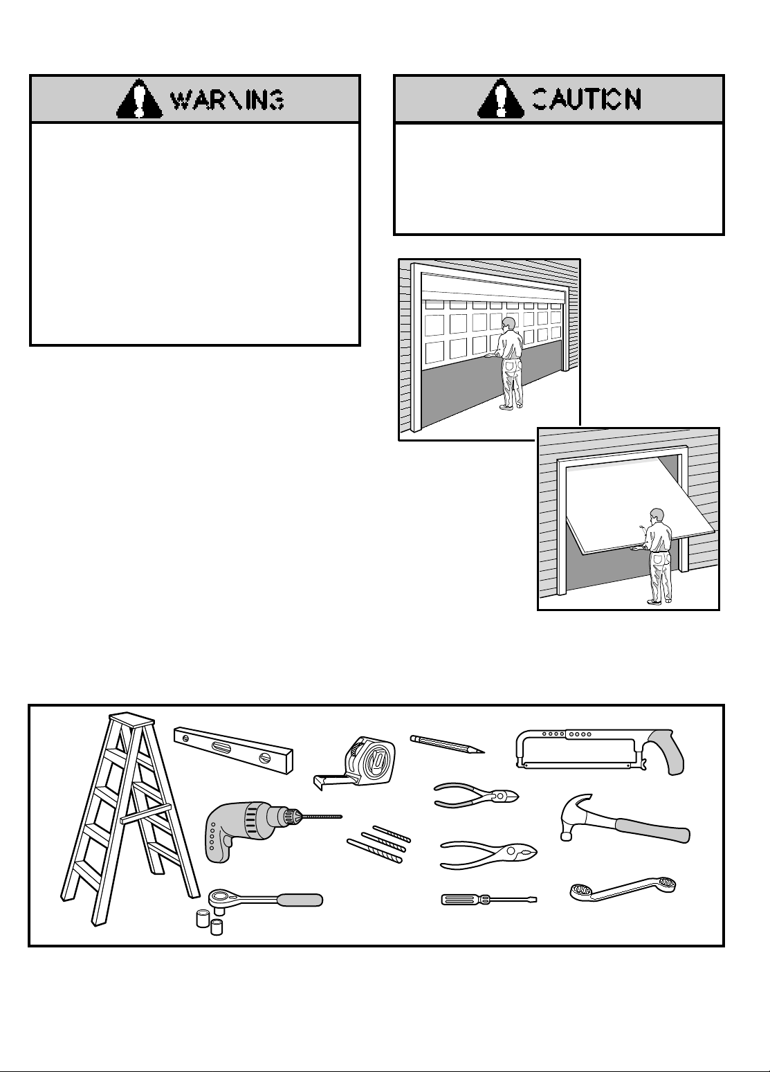
Pliers
Wire Cutters
Claw Hammer
Hack Saw
Screwdriver
1/2" x 7/16" Box Wrench
1/2" and 7/16" Sockets
and Wrench
Drill
Tape Measure
2
1
Stepladder
Pencil
3/16", 5/16", and
5/32" Drill Bits
Carpenter's
Level
Safety Information and Precautions; Tools
An unbalanced gara ge door might not re verse when
required and someone under the door could be seriously
injured or killed.
If your garage door binds, sticks or is out of balance, call
for professional garage door service.
Garage doors, door
springs, cables, pulleys, brackets, and their hardware are
under extreme tension and can cause serious injur y or
death.
Do not tr y to loosen, mo ve or adjust them
yourself!
Ropes left on a gara ge door could cause someone to
become entangled and killed.
Remove all r opes
connected to the door before installing and operating the
opener.
Identify the type and height of your door, any special
conditions that exist, and any additional materials that
may be required. Refer to pages 6 and 7.
Test Your Door for Balance
Before you begin, complete the following test to make
sure your door is balanced, and is not sticking or
binding:
• Lift the door about halfway as shown. Release the door.
It should stay in place, supported entirely by its springs.
• Raise and lower the door to see if there is any binding or
sticking.
To avoid damage to the garage door and opener, disable
locks before installing and operating the opener . Use a
wood screw or nail to hold locks in the "open" (unlocked)
position.
Operation at other than 120V 60 Hz will cause opener
malfunction and damage.
Sectional Door
One-Piece Door
During assembly, installation and adjustment of the opener, instructions will call for tools shown below.
3
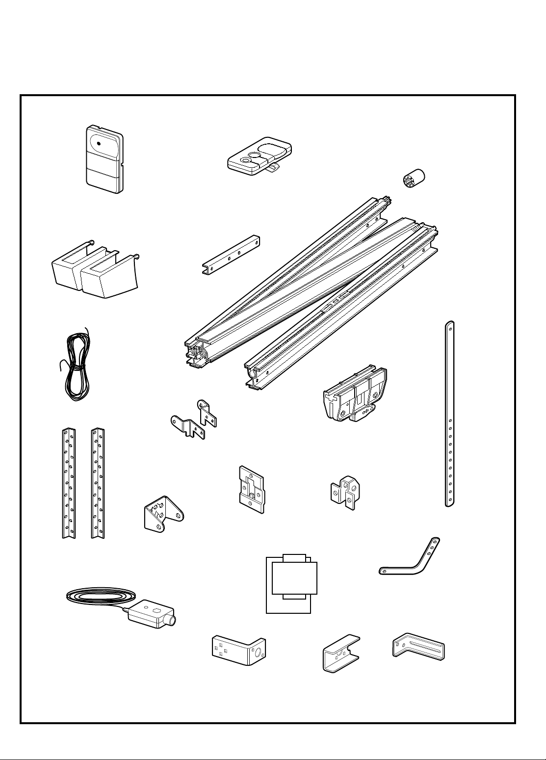
Straight Door
Arm Section
Door Bracket Plate
Door Bracket
Curved Door
Arm Section
Header/Rail
Brackets
Rail Support
Braces (4)
Header Bracket
UP
CEILING MOUNT ONLY
Safety Reversing Sensor
Mounting Bracket
With Square Holes (2)
"C" Wrap (2)
Safety Reversing Sensor
Mounting Bracket
With Slot (2)
Sprocket
Coupling
2-Conductor Bell Wire
White & White/Red
Rail
Assembly
Light Lens
Trolley
Hanging Brackets
Safety Labels
and
Literature
(2) Safety Reversing Sensors
(1 Sending Eye and 1 Receiving Eye)
with attached
2-Conductor White & White/Black Bell Wire
Three-Function Remote Control
with Visor Clip (2)
Standard
Control Console
Carton Inventory
Your garage door opener is packaged in one carton which contains the power unit and all parts illustrated below. If anything
is missing, carefully check the packing material. Parts may be "stuck" in the foam.
10). Hardware for assembly and installation is shown on page 5.
KEEP THE FOAM INTACT (see page
4
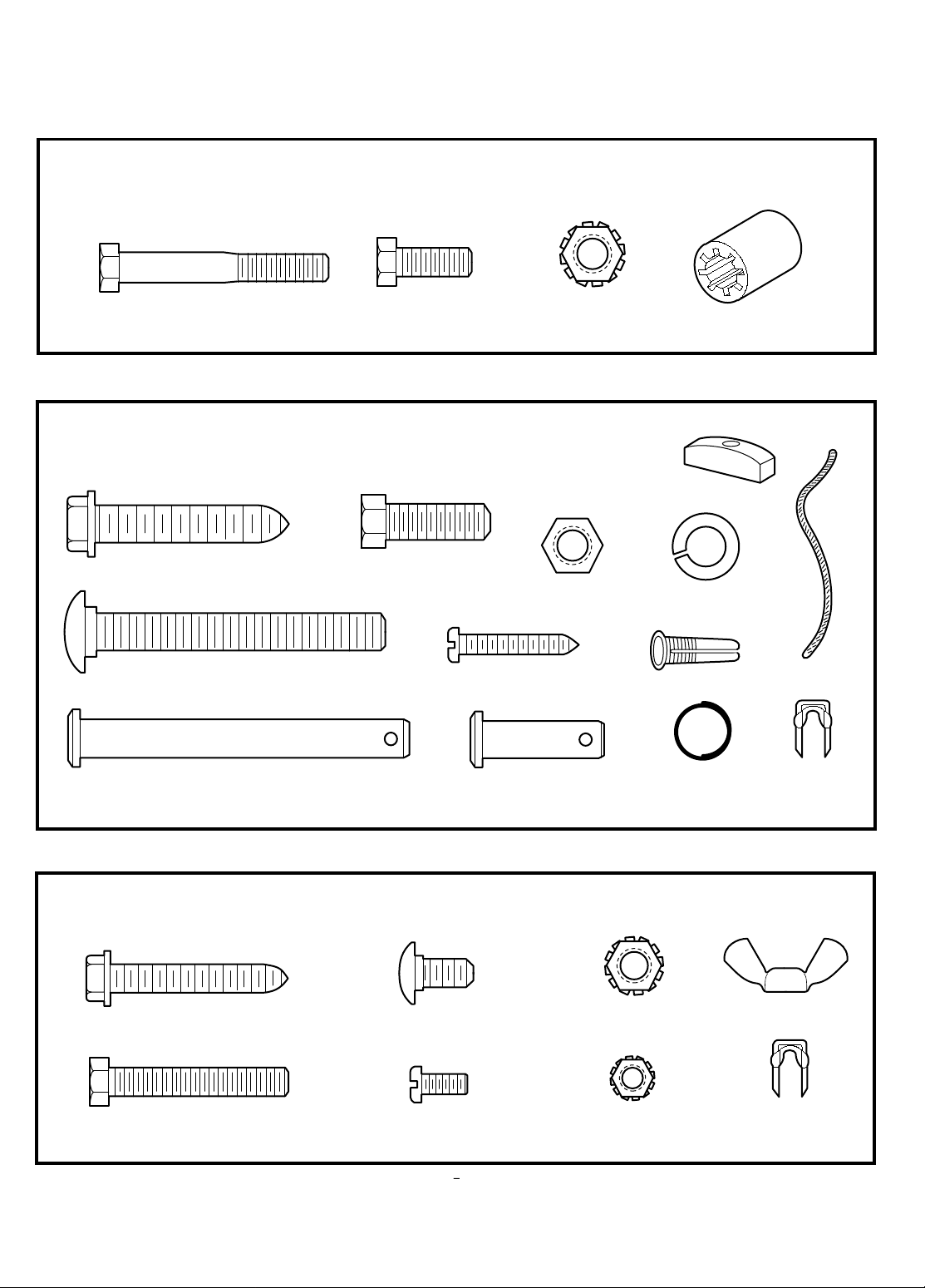
Hardware
Nut 5/16"-18 (6)
Clevis Pin
5/16"x2-3/4" (1)
NOTICE
Handle
Insulated
Staples (10)
Installation Hardware
Dry Wall Anchors (2)
Clevis Pin
5/16"x1" (2)
Hex Screw
5/16"-18x7/8" (4)
Rope
Lock Nut
1/4"-20 x 7/16 (12)
Carriage Bolt
5/16"-18x2-1/2" (2)
Ring
Fastener (3)
Screw
6ABx1" (2)
Lock Washer 5/16" (6)
Lag Screw
5/16"-9x1-5/8" (4)
Lock Nut
1/4"-20 x 7/16 (4)
Carriage Bolt
1/4"-20x1/2" (4)
Safety Reversing Sensor Installation Hardware
Hex Screw
1/4-20x1-1/2" (2)
Screw
#10-32x3/8" (4)
Lock Nut
#10x32 (4)
Wing Nut (2)
Insulated
Staples (20)
Lag Screw
1/4x1-1/2" (4)
1/4" - 20 x 5/8"
Hex Screw (4)
Sprocket Coupling Sleeve
Assembly Hardware
Bolt
1/4-20x1-3/4" (8)
Separate all hardware from the packages in the rail carton and the opener carton and group as shown below, for
the assembly and installation procedures.
5
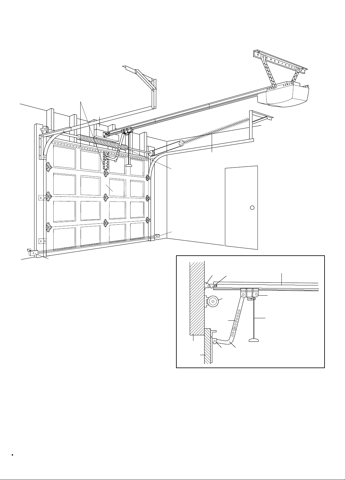
Safety Reversing Sensor
Horizontal and vertical reinforcement
is needed for lightweight garage doors
(fiberglass, steel, aluminum, door with glass panels, etc.).
See page 24 for details.
Support bracket &
fastening hardware
is required.
See page 20.
— — — — — — — —
Door Center
Header Wall
Safety
Reversing
Sensor
Floor must be level
across width of door
FINISHED CEILING
Extension Spring
Torsion Spring
Access Door
OR
Header
Bracket Rail
Bracket
Trolley
Straight
Door
Arm
Emergency
Release
Rope & Handle
Door
Bracket
Garage
Door
Curved
Door
Arm
Garage
Door
Spring
Header
Wall
Rail Assembly
Closed Position
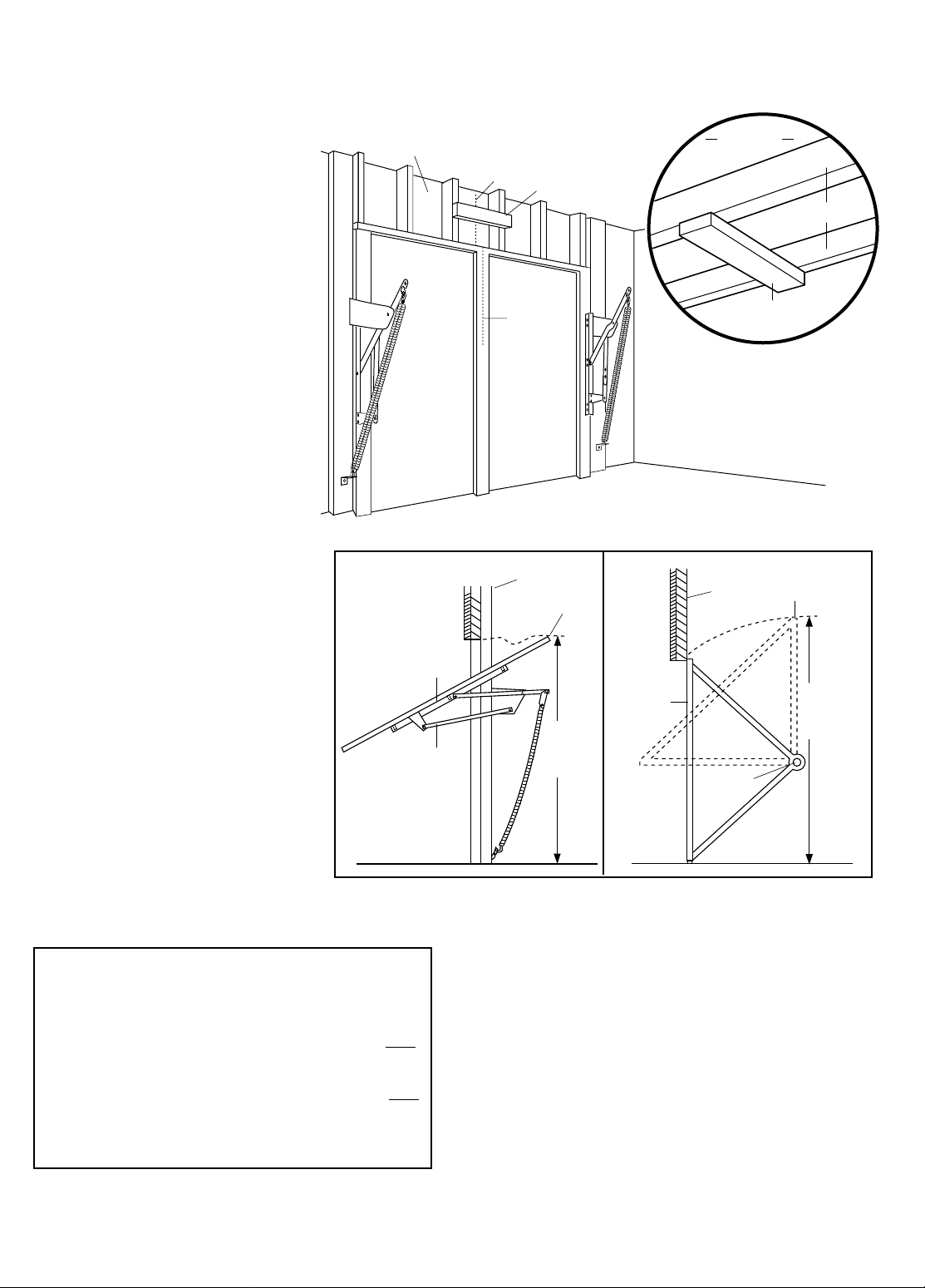
SECTIONAL Door Installation
Before you begin, survey your garage area to
see whether any of the conditions below apply
to your installation.
Based on your particular requirements, there are several
installation steps which might call for materials and/or
hardware not included in the carton.
• Step 1, page 12 – Look at the wall or ceiling above the
garage door. The header bracket
must be securely
fastened to structural supports.
• Safety reversing sensor, page 16 – Depending upon
garage construction, wood blocks may need to be
fastened to mounting locations before sensors are
installed.
• Step 4, page 17 – Alternate floor mounting of the safety
reversing sensor will require hardware not provided.
• Step 6, page 20 – Do you have a finished ceiling in your
garage? If so, a support bracket and additional fastening
hardware may be required.
• Step 12, page 24 – Do you have a steel, aluminum,
fiberglass or glass panel door? If so, horizontal and
vertical reinforcement is required.
• Look at the garage door where it meets the floor. It
must close on the floor all the way across. Otherwise,
the safety reverse system may not work properly. See
page 30. Floor or door should be repaired.
• The opener can be installed within 2 feet of the left or
right of the door center if there is a torsion spring or
center bearing plate in the way of the header bracket or
door bracket area. If your door has extension springs,
the opener must be installed in the center of the door.
See pages 12 and 24.
• Do you have an access door in addition to the garage
door? If not, Model 18752 Outside Trolley Release is
required. See page 38.
You may find it helpful to refer back to this page as
you proceed with the installation of your opener.
6
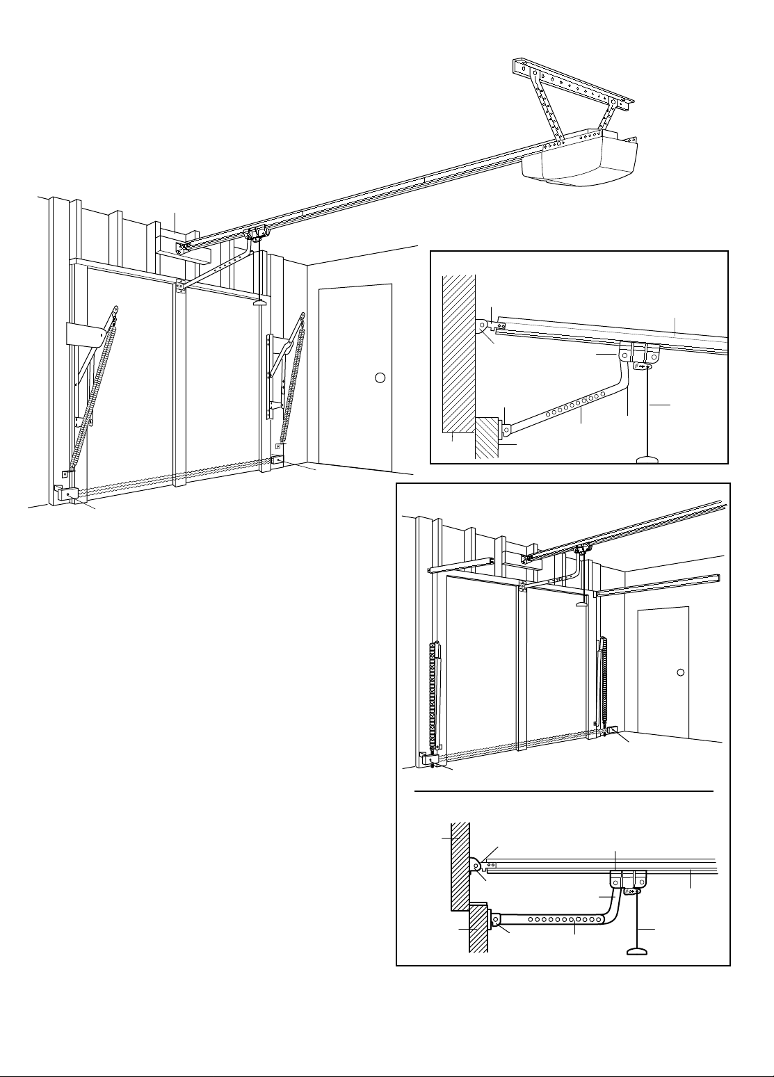
Safety Reversing Sensor
FINISHED CEILING
Support bracket
& fastening
hardware is required.
See page 20.
Safety Reversing
Sensor
Header
Wall
Access Door
Gap between floor and bottom of
door must not exceed 1/4".
Closed Position
Header
Bracket
Trolley
Emergency
Release
Rope & Handle
Door
Bracket
Header
Wall
Rail Assembly
Straight
Door
Arm
Curved
Door
Arm
Garage
Door
Rail
Bracket
ONE-PIECE Door Installation
Access
Door
Floor must be level
across width of door
Safety
Reversing Sensor
Door
Bracket
Straight
Door
Arm
Curved
Door Arm
Safety
Reversing
Sensor
One-Piece Door With Track
Closed Position
Header
Bracket
Trolley
Emergency
Release
Rope & Handle
Rail Assembly
Garage
Door
Header
Wall
Rail
Bracket
Before you begin, survey your garage area to
see whether any of the conditions below apply
to your installation.
One-Piece Door without Track
Based on your particular requirements, there are several
installation steps which might call for materials and/or
hardware not included in the carton.
• Step 1, page 13 – Look at the wall or ceiling above the
garage door. The header bracket
must be securely
fastened to structural supports.
• Step 6, page 20 – Do you have a finished ceiling in your
garage? If so, a support bracket and additional fastening
hardware (not supplied) may be required.
• Safety reversing sensor, page 16 – Depending on garage
construction, wood blocks may need to be securely
fastened to mounting locations before sensors are
installed.
• Step 14, page 17 – Alternate floor mounting of the
safety reversing sensor will require hardware that is not
provided.
• Step 12, page 25 – Generally, a one-piece door does not
require reinforcement. If your door is lightweight, you
can refer to the information relating to sectional doors
on page 24.
• Step 12, page 25 – Depending on your door's
construction, you might need additional mounting
hardware for the door bracket.
• Do you have an access door in addition to the garage
door? If not, Model 18752 Outside Trolley Release is
required. See page 38.
• The gap between the bottom of the garage door and
the floor cannot exceed 1/4". Otherwise, the safety
reverse system may not work properly. See page 30.
The floor or the door should be repaired.
You may find it helpful to refer back to this page as
you proceed with the installation of your opener.
7
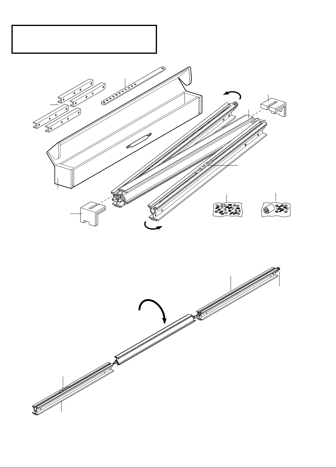
Center
Rail
Trolley Rack
Extend
End Rails
Outward
Extend
End Rails
Outward
Rail Assembly
Carton
Remove
Cardboard Packing
Remove
Cardboard Packing
Rail
Support
Braces
Straight
Door Arm
Rail Assembly
Hardware Bag
Chassis Assembly
Hardware Bag
ASSEMBLY SECTION: PAGES 8 - 11
Center Rail
Door End Rail
Rail
Sprocket
Trolley Rack
Sprocket End Rail
Rotate
Assembly Step 1
Assemble the Rail
To avoid installation difficulties, do not run the garage
door opener until instructed to do so.
1. Turn the opened rail carton upside down, emptying its
contents onto a level work surface.
2. Unfold the rails, taking care to avoid kinking the screw
rod joints.
3. Rotate the rail sections so that the flat side is down and
the screw side is up for all three lengths. Keep it clean
and free of debris while you are working.
CAUTION: During assembly, avoid pulling the rail
section housing the trolley rack away from the screw
rod. The rack is factory set about 9" from the end of the
screw rod to the center of the rack.
If the plastic liner slides part way out during assembly,
simply push it back in.
8
Center Rail
Slide End
Rails Towards
Center Rail
Slide End
Rails Towards
Center Rail
Rail
Support
Brace
Lock
Nuts
Center
Rail
Rail Pin
Alignment
Hole
Rail
Support
Brace
Rail Pin
Rail Pin
Alignment
Hole
Alignment
Hole
1/4x20x1-3/4"
Bolts
1/4x20x1-3/4"
Bolts
Lock
Nuts
End
Rail
Door End
Sprocket End
1/4" - 20
Lock Nut
1/4"-20
Lock Nut
1/4" - 20 x 5/8"
Hex Screw
Hex Screw
5/16"-18 x 7/8"
Nut 5/16"-18 Lock Washer 5/16"
Bolt
1/4-20x1-3/4" (8)
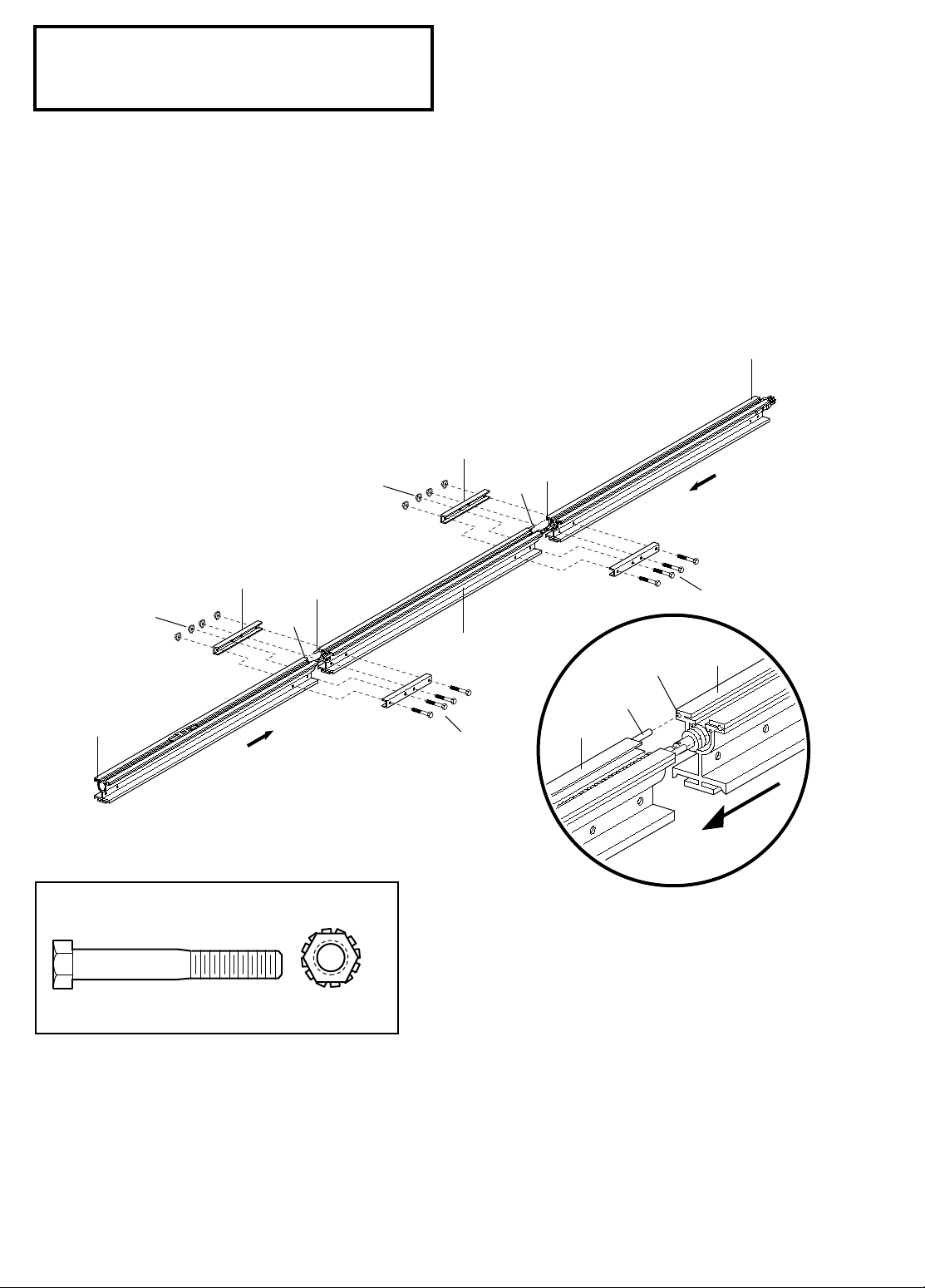
Assembly Step 1 (Continued)
Assemble the Rail
4. Beginning with the sprocket end, straighten the two
rail sections so that the screw rod is in a straight line at
the joint. (Avoid handling the joints, which may have
sharp edges.)
5. Carefully slide the pins at the top edge of the rail into
the openings on the adjacent rail.
It is essential that
the rail assembly be on a level surface to achieve
proper alignment and to avoid damage to the pins.
6. Insert two 1/4"-20x1-3/4" bolts through the
center
holes of a brace, and place its open length against the
rail at this joint, aligning the holes as shown. Position
another brace on the opposite side of the rail over the
bolts, add 1/4"-20 lock nuts, and hand tighten. Insert
two additional bolts and hand tighten.
7. Keeping the rail straight and on a level surface, grasp
the screw rods on each side of the remaining joint and
pivot into a straight line. Repeat steps 5 and 6.
8. With a 7/16 wrench, tighten bolts til snug, working
from the center holes of the braces to those further
from the joints. Do not overtighten.
Hardware Shown Actual Size
9
Assembly Step 2
Rail
Sprocket
Rail
Assembly
Trolley
Coupling
Rail/Power Unit
Bracket
Lock Nuts
1/4"-20
Power Unit
Sprocket
Power
Unit
Foam Packaging
Hex Screws
1/4"-20x5/8"
1/4" - 20
Lock Nut
1/4" - 20 x 5/8"
Hex Screw
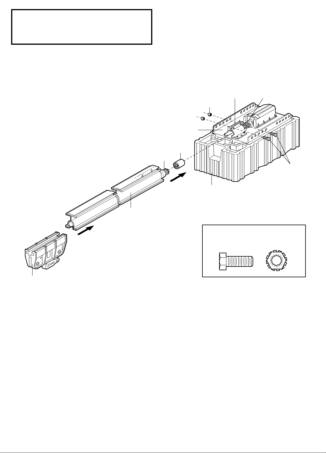
Fasten the Rail To the Power Unit
and Install the Trolley
NOTE: To aid in assembly and installation, replace
the foam packing around the power unit. Remove it
after Installation Step 5.
• Working on a level surface, align the rail assembly with
the power unit, as shown.
• Slip the coupling over the rail sprocket.
• Slide the rail through the power unit bracket until the
coupling fits securely over the power unit sprocket.
• Align the two screw holes in the rail with those in the
power unit bracket. Insert two 1/4"-20x5/8" hex screws
and lock nuts. Tighten securely with a 7/16" socket
wrench.
As illustrated above, slide the trolley onto and along the
bottom of the rail until it snaps firmly in place.
Be certain
to install it facing correctly: the trolley release arm must
be horizontal (lock position), with its arrow pointed
away from the power unit.
Hardware Shown Actual Size
10
Assembly Step 3
Rail
Brackets
Rail
1/4"-20
Lock Nuts
1/4"-20x5/8
Hex
Screws
WARNING
WARNING
WARNING
1/4" - 20
Lock Nut
1/4" - 20 x 5/8"
Hex Screw
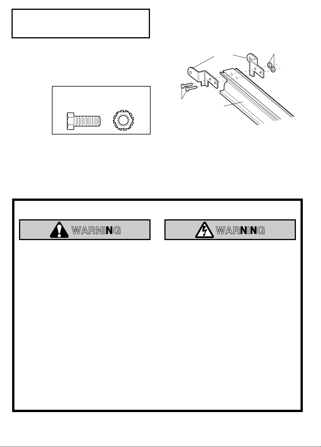
Attach the Rail Brackets
• Align rail brackets to end of rail assembly, as shown.
• Insert two 1/4"-20 x 5/8" hex screws and lock nuts.
Tighten securely with a 7/16" socket.
Hardware Shown Actual Size
You have now finished assembling your garage door opener. Please read the following warnings
before proceeding to the installation section:
IMPORTANT INSTALLATION INSTRUCTIONS
To reduce the risk of severe injury or death to persons:
1. READ AND FOLLOW ALL INSTALLATION INSTRUCTIONS
2. Install only on a properly balanced and lubricated garage door.
reverse and could result in severe injury or death. Repairs to cables, spring assemblies and other hardware
must be made by a professional service person before installing opener.
3. Disable all locks and remove all ropes connected to the garage door before installing the opener. Ropes
connected to a garage door can cause entanglement and death.
4. If possible, install door opener 7 feet or more above floor with the emergency release handle mounted 6
feet above the floor.
5. Do not connect the opener to power source until instructed to do so.
6. Locate the Door Control within sight of the door at a minimum height of 5 feet where small children
cannot reach and away from all moving parts of the door.
7. Install the User Safety Instruction Label on the wall adjacent to the control button and the Maintenance
Instruction Label in a prominent location on the inside of the garage door.
8. Upon completion of the installation, the door must reverse when it comes in contact with a one-inch high
object or a 2x4 laid flat on the floor.
An improperly balanced door may not
9. Do not wear watches, rings or loose clothing while installing or servicing an opener. Jewelry or loose
clothing can be caught in the mechanism of the garage door or the opener.
11
Header
Wall
Ceiling
Track
Highest Point
of Travel
Door
Door
Track
SECTIONAL DOOR AND
ONE-PIECE DOOR WITH TRACK
3"
Header
Wall
Highest Point
of Travel
3"
SECTIONAL DOOR AND
ONE-PIECE DOOR WITH TRACK
Vertical
Guideline
Finished
Ceiling
Vertical
Guideline
Header
Wall
2x4
Structural
Supports
INSTALLATION SECTION: PAGES 12 – 27
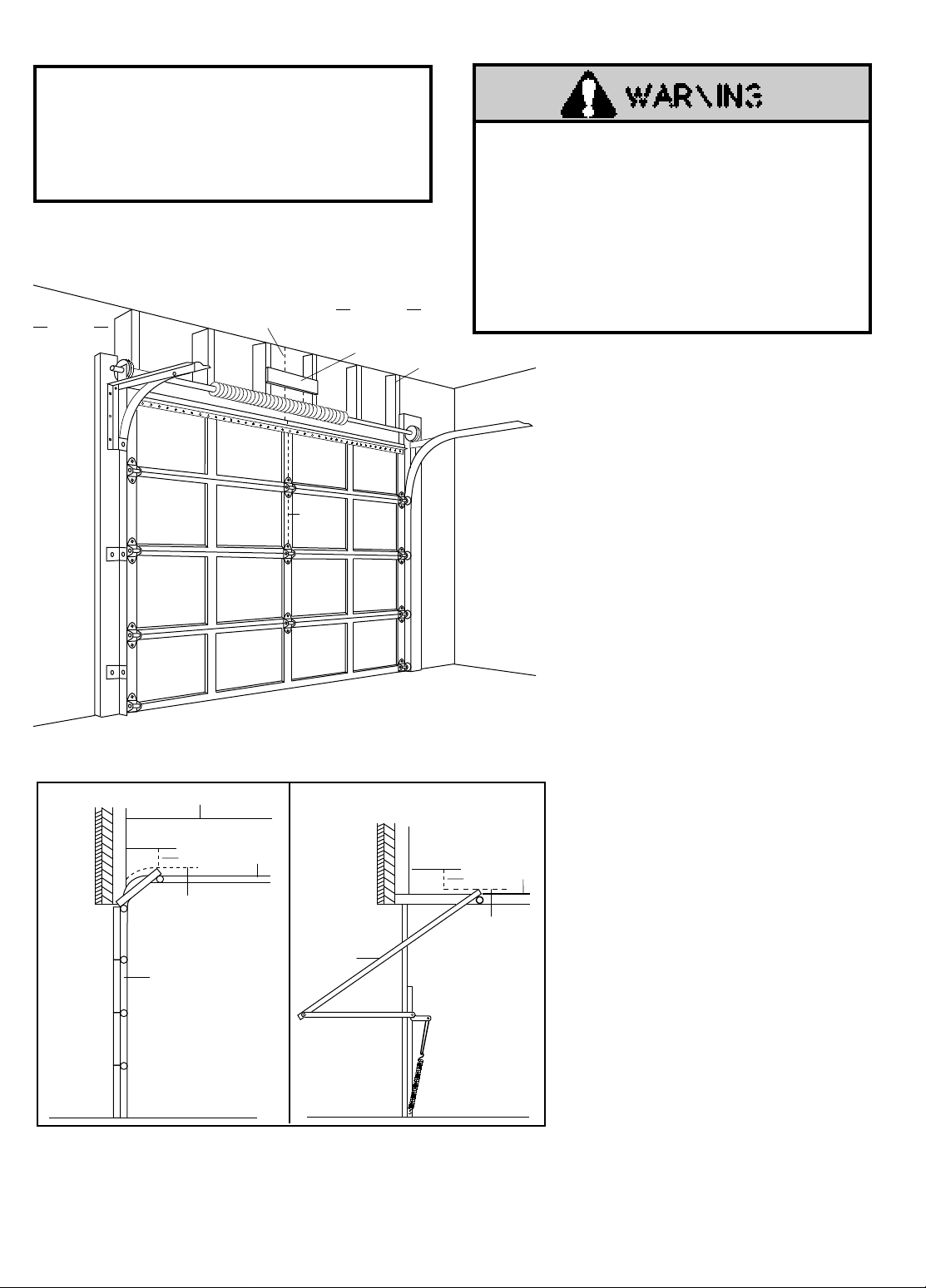
Installation Step 1
Determine Header Bracket Location
Installation procedures vary according to garage
door types. Follow the instructions which apply to
your door.
Sectional door
with curved track
If the header bracket is not rigidly fastened to a
structural support on the header wall or ceiling, the
safety reverse system may not work properly (see
page 30).
The door might not reverse when required, and
could cause serious injury or death.
The garage door springs, cables, pulleys, brackets and
their hardware are under extreme tension.
to loosen, move or adjust them yourself. Serious
personal injury or death could result.
professional garage door service.
SECTIONAL Door or
ONE PIECE Door with Track
• Close the door and mark the inside
vertical centerline of the garage door.
• Extend the line onto the header wall
above the door.
Remember, you can fasten the header
bracket within 2 feet of the left or right
of the door center
spring or center bearing plate is in the
way; or you can attach it to the ceiling
One-piece door
with horizontal track
(refer to page 14) when clearance is
minimal. (It may be mounted on the
wall upside down if necessary, to gain
approximately 1/2".)
If you need to install the header bracket on
a 2x4 (on wall or ceiling), use lag screws
(not supplied) to securely fasten the 2x4 to
structural supports as shown here and on
page 13.
• Open your door to the highest point of
travel as shown. Draw an intersecting
horizontal line on the header wall 3"
above the high point. This height will
provide travel clearance for the top edge
of the door.
• Door clearance brackets are available
for sectional doors when headroom
clearance is less than 2". See accessory
page 38.
Proceed to Step 2, page 14.
Do not attempt
Call for
only if a torsion
12
Header Wall
Vertical
Centerline
Vertical
Centerline of
Garage Door
2x4
Unfinished
Ceiling
Structural Supports
2x4
Header Support
OPTIONAL CEILING MOUNT
FOR HEADER BRACKET
Door
Highest Point
of Travel
Header
Wall
Pivot
Distance
Header Wall
Highest Point
of Travel
Door
Floor
Floor
Distance
Jamb
Hardware
ONE-PIECE Door Without Track
Read the Safety Instructions on page 12. They also apply to doors without tracks.
• Close the door and mark the inside
vertical centerline of your garage door.
Extend the line onto the header wall
above door.
If headroom clearance is minimal, you
can install the header bracket on the
ceiling. See page 14.
If you need to install the header
•
bracket on a 2x4 (on wall or ceiling),
use lag screws (not supplied) to
securely fasten the 2x4 to structural
supports as shown.
• Open your door to the highest point of
travel as shown. Measure the distance
from the top of the door to the floor.
Subtract the actual height of the door.
Add 8" to the remainder. (See
Example).
• Close the door and draw an
intersecting horizontal line on the
header wall at the determined height.
If the total number of inches exceeds
the height available in your garage,
use the maximum height possible, or
refer to page 14 for ceiling
installation.
Proceed to Step 2, page 14.
EXAMPLE
Distance from top of door
(at highest point of travel) to floor . . . . . . . . . . . . .92"
Actual height of door . . . . . . . . . . . . . . . . . . . . . .-88"
Remainder . . . . . . . . . . . . . . . . . . . . . . . . . . . . . . . .4"
Add . . . . . . . . . . . . . . . . . . . . . . . . . . . . . . . . . . . .+8"
Bracket height on header wall . . . . . . . . . . . . . . .=12"
(Measure UP from top of CLOSED door.)
One-piece door without track
jamb hardware
One-piece door without track
pivot hardware
13
Lag Screws
5/16"x9x1-5/8"
Highest
Point of Travel
(of Garage Door)
Vertical
Center
Line
Header
Wall
Garage
Door
UP
CEILING MOUNT ONLY
Wall
Mounting Holes
Optional
Wall Mounting
Holes
The nail hole is for
positioning only.
You must use lag screws
to mount the header bracket.
UP
CEILING MOUNT ONLY
Door
Spring
Header
Bracket
2x4
Structural
Support
Vertical
Center
Line
Installation Step 2
UP
CEILING MOUNT ONLY
Ceiling Mounting Holes
The nail hole is for
positioning only.
You must use lag screws
to mount the header bracket.
UP
Lag Screws
5/16"x9x1-5/8"
Garage
Door
Vertical
Center Line
Header
Wall
– Finished Ceiling –
Header
Bracket
6"
Maximum
Vertical
Center Line
Door
Spring
Lag Screw
5/16"-9 x 1-5/8"
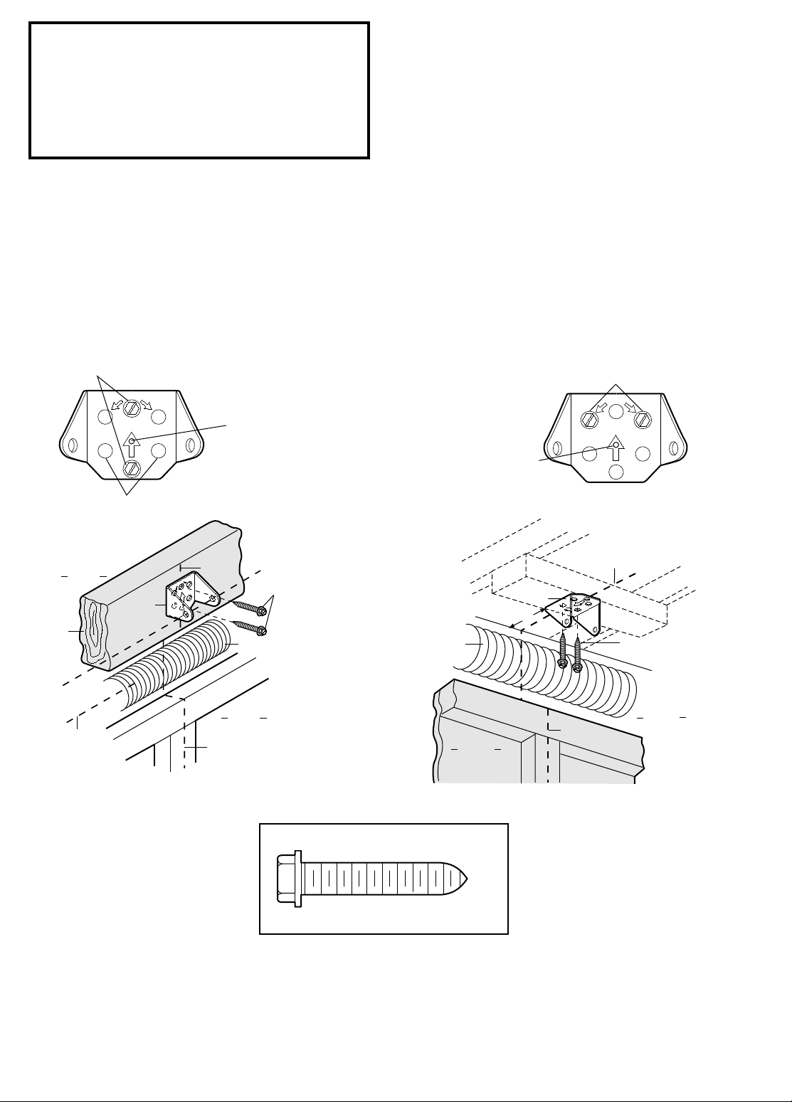
Install the Header Bracket
You can attach the header bracket either to the
wall above the garage door, or to the ceiling.
Follow the instructions which will work best for
your particular requirements.
Fastening the Header Bracket to the Wall
• Center the bracket on the vertical guideline with the
bottom edge of the bracket on the horizontal line as
shown (with the arrow pointing toward the ceiling).
• Mark either set of bracket holes (do not use the holes
designated for ceiling mount). Drill 3/16" pilot holes
and fasten the bracket securely to a structural support
with the hardware provided.
Fastening the Header Brac ket to the Ceiling
• Extend the vertical guideline onto the ceiling as shown.
• Center the bracket on the vertical mark, no more than 6"
from the wall. Make sure the arrow is pointing toward
the wall. The bracket can be mounted flush against the
ceiling when clearance is minimal.
• Mark holes designated for ceiling mount only. Drill
3/16" pilot holes and fasten bracket securely to a
structural support with the hardware provided.
Hardware Shown Actual Size
14
Clevis Pin
5/16" x 2-3/4"
Ring Fastener
Header Bracket
Rail Bracket
Foam Packaging
Opener Carton or
Temporary
Support
Header Wall
Garage
Door
Rail
Clevis Pin
5/16"x2-3/4 "
Ring Fastener
Header Bracket
Rail
Bracket
Rail
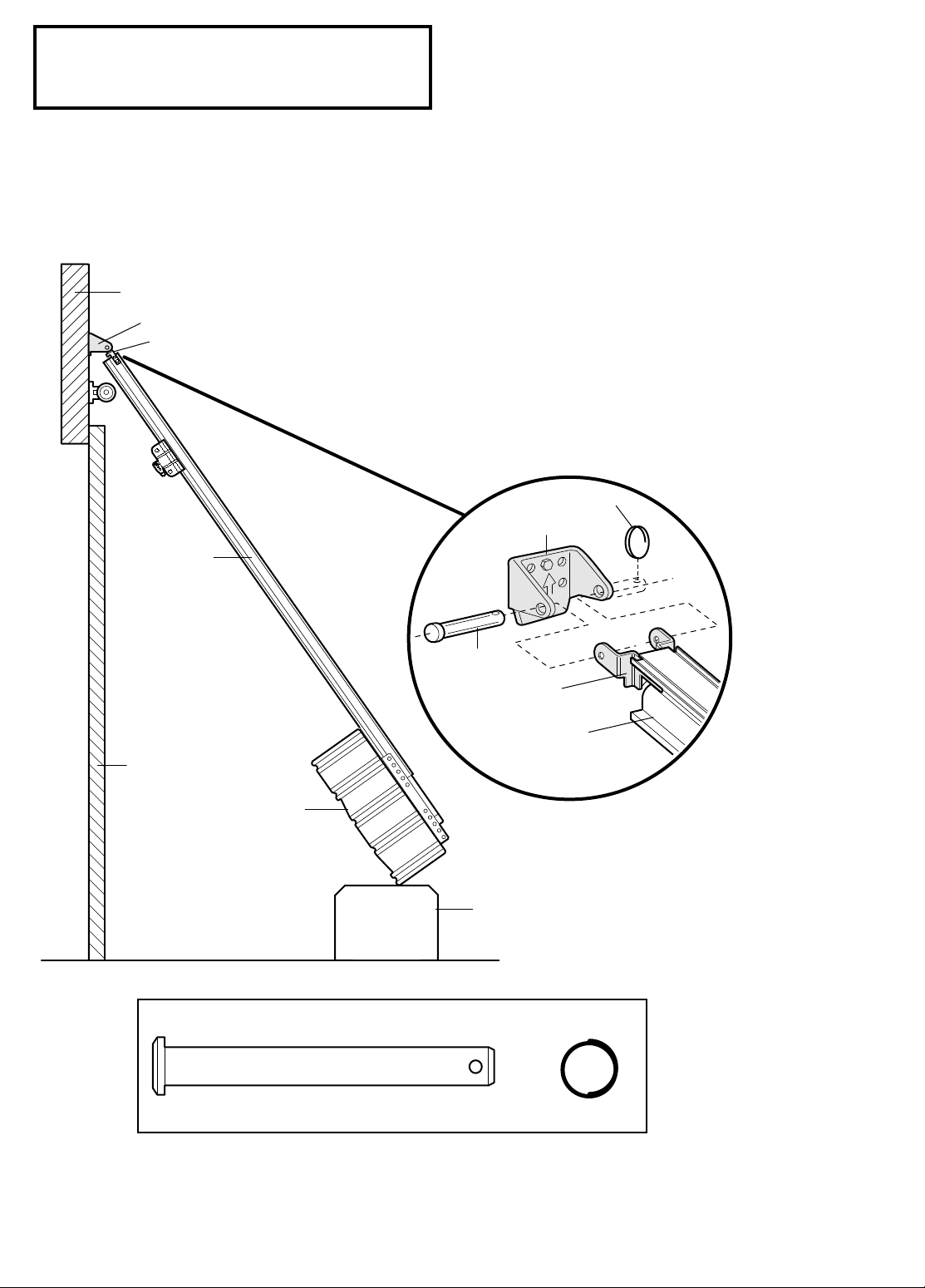
Installation Step 3
Attach the Rail to the Header Bracket
• Position the opener on the garage floor below the
header bracket. Use packing material as a protective
base.
If the door spring is in the way you’ll need help. Have
someone hold the opener securely on a temporary
support to allow the rail to clear the spring.
• Position the rail bracket against the header bracket.
• Align the bracket holes and join with a clevis pin as
shown.
• Insert a ring fastener to secure.
Hardware Shown Actual Size
15
Invisible Light Beam
Protection Area
Sensor
Beam
4-6" max.
above floor
Sensor
Beam
4-6" max.
above floor
The Safety Reversing Sensor
Information you'll need before you begin the installation of the safety reversing sensor
The safety reversing sensor
must be connected and
aligned correctly before the garage door opener will
move in the down direction. This is a required safety
device and cannot be disabled.
Installation procedures are the same for sectional and
one-piece doors.
Be sure power to the opener is disconnected.
The sending eye transmits an invisible light beam to the
receiving eye. The units can be installed on either side of
the garage door as long as the sun never shines directly
into the receiving eye lens.
Look at the label on the connector end of each case to
identify the sensors.
The brackets must be connected and fastened so that the
sending and receiving eyes face each other as shown.
If an obstruction breaks the light beam while the garage
door is closing, the door will stop and reverse to full open
position and the opener lights will flash for 5 seconds.
The brackets must be securely fastened to a solid surface
such as the studs on either side of the door, or add a piece
of wood at each location if installing in masonry
construction.
Without a properly working safety reversing sensor,
persons (particularly children) could be injured or killed
by a closing garage door.
Read and follow all
instructions.
To protect small children, install the safety reversing
sensor so that the beam will be no higher than 4"-6"
above the garage floor.
Disconnect power to the garage door opener before
installing the safety reversing sensor.
The invisible light beam path must be unobstructed. No
part of the garage door (or door tracks, springs, hinges,
rollers or other hardware) can interrupt the beam while
the door is closing. If it does, use a piece of wood to build
out each sensor mounting location to the minimum depth
required for light beam clearance.
Facing the door from inside the garage
16
1/4 x 1-1/2"
Lag Screw
#10 - 32 x 3/8"
Screw
1/4" - 20
Lock Nut
#10-32
Lock Nut
Staples
1/4" - 20 x 1/2"
Carriage Bolts
Installation Step 4
Mounting Bracket
With Square Holes
#10-32x3/8"
Screws
"C" Wrap
#10 - 32
Lock Nuts
Mounting Bracket
with Slot
1/4" - 20
Lock Nuts
1/4 x 1-1/2"
Lag Screws
1/4-20 x 1/2" Carriage Bolts
(with square shoulder)
Inside
Garage
Wall
"C" Wrap
Mounting Bracket
with Square Holes
"C" Wrap
Inside
Garage
Wall
Mounting Bracket
with Square Holes
Garage
Floor
Mounting Bracket
with Slot
Alternate Wall Mount
Sensor
with wire
Indicator Light
Indicator Light
Inside
Garage
Wall
Alternate Floor Mount
Mounting Bracket
with Slot
Attach with
concrete anchors
(not provided)
Mounting Bracket
with Square Holes
"C" Wrap
Sensor with wire
Garage
Floor
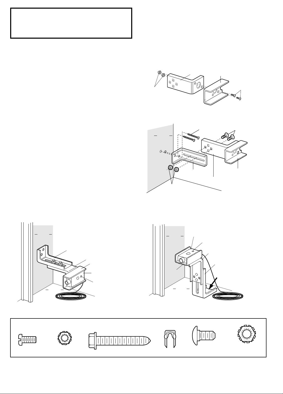
Install the Safety Reversing Sensor
(Receiving and Sending Eyes)
Figures 1 and 2 show assembly of brackets and "C" wrap
based on the recommended installation of the sensors on
each side of the garage door as shown on page 16.
However, Figures 3 and 4 are variations which may fit
your installation requirements better.
Make sure the
wraps and brackets are aligned so the sensors will face
each other across the garage door.
1. Fasten the "C" wraps to the mounting brackets having
square holes, using the hardware shown in Figure 3.
2. Connect each assembly to a slotted bracket, using the
hardware shown in Figure 2.
Note the alignment of the brackets for left and right
sides of the door.
3. Finger tighten the lock nuts.
4. Use bracket mounting holes as a template to locate and
drill (2) 3/16" diameter pilot holes on both sides of the
garage door, 4"-6" above the floor
but not exceeding
6". (See warning on page 16.)
5. Attach bracket assemblies with 1/4"x1-1/2" lag screws
as shown in Figure 2.
6. Adjust right and left side bracket assemblies to the
same distance out from the mounting surface. Make
sure all door hardware obstructions are cleared.
Tighten the nuts securely.
Figure 1
Figure 2
Figure 3
Figure 4
Hardware Shown Actual Size
17
1/4-20 x 1-1/2"
Hex Bolt
"C" Wrap
Sensor
with Wire
Wing
Nut
Indicator
Light
Installation Step 4 (Continued)
The Chamberlain Group, Inc.
Screw Drive CGI
Sensor Wiring to Chassis
1/13/95
Invisible Light Beam
Protection Area
Sensor
Sensor
Bell Wire
Foam
Packaging
Carton
2. Run wires along channels
to power unit and pull taut.
1. Run wires from sensors to end of rail
at the door header. Cross & twist here to
help contain wires in channels on
top
of rail.
3. Thread wires through tabs
on top of Drive Shaft Cover.
4. With screwdriver blade,
tuck wires snugly into channels.
Header
Bracket
Header
Wall
Sensor
Wire
Twist
Wires
Sensor
Wire
Rail
Channel
1/4-20 x 1-1/2"
Hex Bolt
Wing Nut
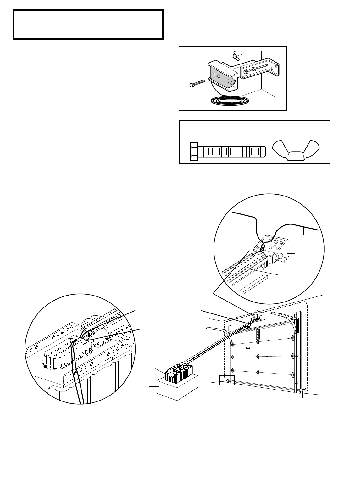
Install the Safety Reversing Sensor
7. Center each sensor unit in a “C”- wrap with lenses
pointing toward each other across the door (see
Figure 5).
8. Secure sensors with the hardware shown. Finger
tighten the wing nut on the
final adjustment. Securely tighten the sending eye
wing nut.
receiving eye to allow for
Recommended Wire Routing
1. Using insulated staples, run the wires from both
sensors to the rail at the door header (see Figure 6).
2. Cross and twist the two wires where they meet the rail
(see inset A). Run the wires inside the channels at the
top of the rail, along each side, to the power unit and
pull taut (see inset B). Do not use the lower (trolley)
channels.
NOTE: If your access door is near the garage door,
you may choose to install the wall control at this time
and run the wall control wire along the rail with the
sensor wires. Use one rail channel for the wall control
wire and the other channel for both sensor wires. If
you choose this option, follow instructions 1-3
on page 21 now.
3. Thread the wires through the tabs on top of the drive
shaft cover.
4. With your screwdriver tip, tuck the wires snugly into
the rail channels. You will complete the wiring in
Installation Step 7.
Figure 6
B
Figure 5
Hardware Shown Actual Size
A
18

Installation Step 5
Rail
2x4
Door
Foam
Packaging
Rail
2x4
Door
Top of Opener
Header
Bracket
Top of Door
Foam
Packaging
Foam
Packaging
NOTICE
Emergency
Release
Handle
(Pull at 45° angle)
Trolley
Trolley
Trolley
Release Arm
Trolley
ReleaseArm
Trolley
Trolley
Release Arm
Position the Opener
Follow instructions which apply to your door type
as illustrated.
SECTIONAL Door or ONE-PIECE Door with Track
A 2x4 laid flat is convenient for setting an ideal doorto-rail distance.
• Raise the opener onto a stepladder.
You will need help at this point if the ladder is not tall
enough.
• Open the door all the way and place a 2x4 laid flat on
the top section beneath the rail.
If the top panel hits the trolley when you raise the door,
pull down on the trolley release arm to disconnect the
inner and outer sections. The trolley can remain
disconnected until Step 13 is completed.
To prevent damage to steel, aluminum, fiberglass or
glass panel doors, do not rest the opener on the door
without using a 2x4.
ONE-PIECE Door without Track
• With the door fully open and parallel to the floor,
measure the distance from the floor to the top of the
door.
• Using a stepladder as a support, raise the opener to the
same distance as the door from the floor (it will be at a
slight angle as shown).
• The top of the door should be level with the top of the
opener. Do not position the opener more than 3" above
this point.
19
Installation Step 6
Measure
Distance
Lag Screws
5/16"x1-5/8"
Bracket
(Not Supplied)
Lag Screws
5/16"x1-5/8"
(Not Supplied)
5/16"-18x7/8" Screw
5/16" Lock Washer
5/16"-18 Nut
— FINISHED CEILING —
5/16"-18x7/8"
Hex Screws
5/16" Lock Washers
5/16"-18 Nuts
Hidden
Support
5/16"-18x7/8" Screw
5/16" Lock Washer
5/16"-18 Nut
Structural
Supports
CONTROL
CENTER
CONTROL
CENTER
Preferred Range of
Bracket Placement
Preferred Range of
Bracket Placement
Lag Screw
5/16"-9 x 1-5/8"
Hex Screw
5/16"- 18 x 7/8"
Nut 5/16" - 18
Lockwasher 5/16"
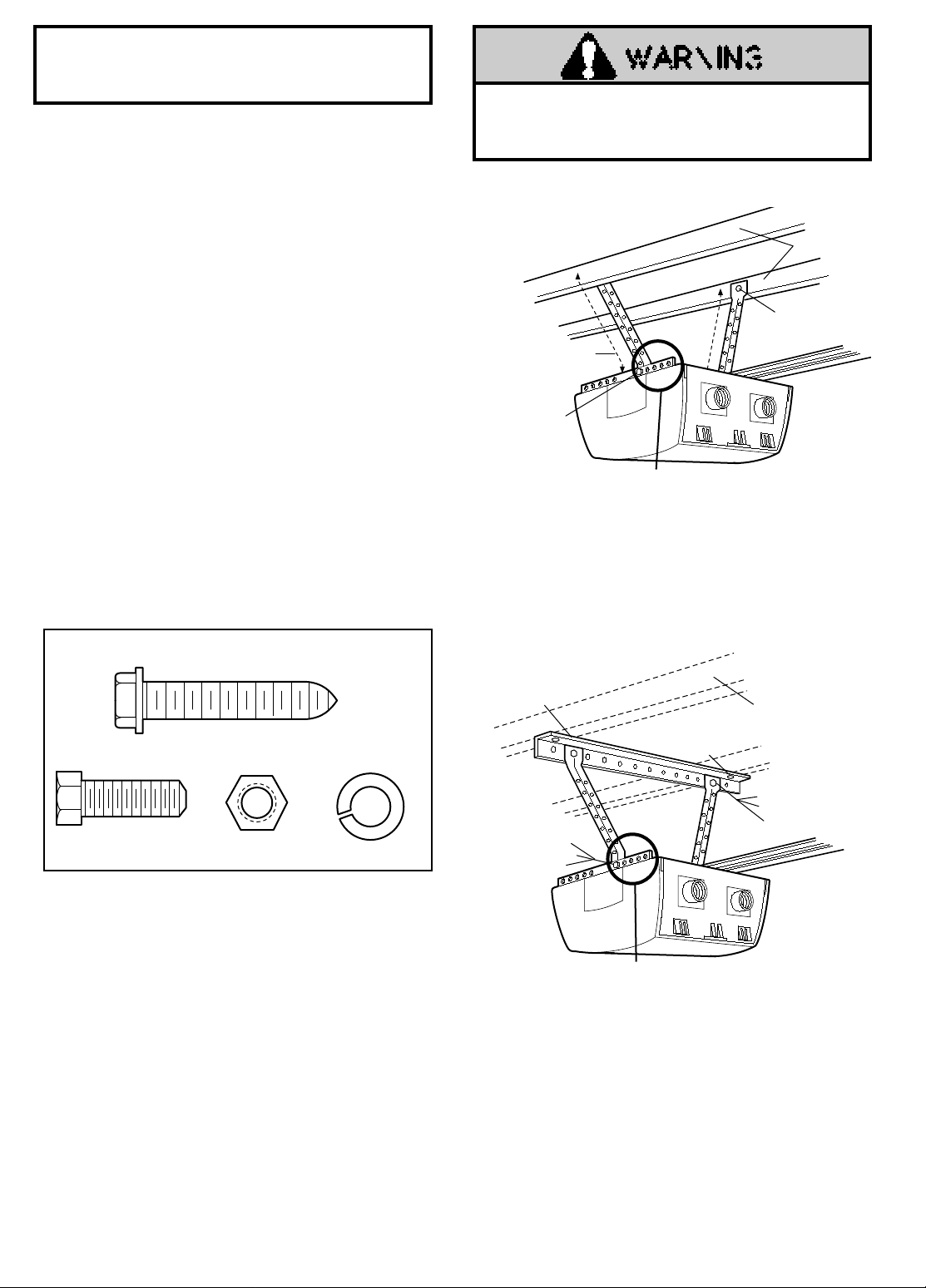
Hang the Opener
Two representative installations are shown. Yours may
be different.
1, to provide rigid support. On finished ceilings, Figure 2,
attach a sturdy metal bracket to structural supports before
installing the opener.
are not supplied.
1. Measure the distance from each side of the opener to
the structural support.
2. Cut both pieces of the hanging bracket to required
lengths.
3. Drill 3/16" pilot holes in the structural supports.
4. Attach one end of each bracket to a support with
5/16"x1-5/8" lag screws.
5. Fasten the opener to the hanging brackets with
5/16" - 18x7/8" screws, lock washers and nuts.
6. Check to make sure the rail is centered over the door
(or in line with the header bracket if the bracket is not
centered above the door).
7. Remove the 2x4. Operate the door manually. If the
door hits the rail, raise the header bracket.
Hanging brackets should be angled, Figure
The bracket and fastening hardware
The opener could fall and injure someone if it is not
properly secured.
Fasten the opener securel y to
structural supports of the garage.
Figure 1
Hardware Shown Actual Size
Figure 2
20
STANDARD
CONTROL
CONSOLE
Lighted
Push
Button
Bell
Wire
Terminal
Screws
(BACK VIEW)
Top
Mounting
Hole
Bottom
Mounting
Hole
WHITE
2
RED
1
Installation Step 7
WARNING
WARNING
OPENER TERMINAL SCREWS
(In Control Center)
Sensor
Connections
Door Control
Connections
(dotted line)
1
2
3
To
Door
Control
To
Sensors
Terminal
Screws
Control
Center
Dry Wall Anchors
Insulated
Staples
6AB x 1-1/4" Screw
Control Console (std installation)
6-32 x 1" Screw
Control Console (pre-wired)
To Replace,
Insert
Top Tabs
First
To Remove,
Twist
Here
PRE-WIRED
INSTALLATION
REMOVE & REPLACE COVER
Figure 1 Figure 2
24 Volt
2-Conductor
Bell Wire
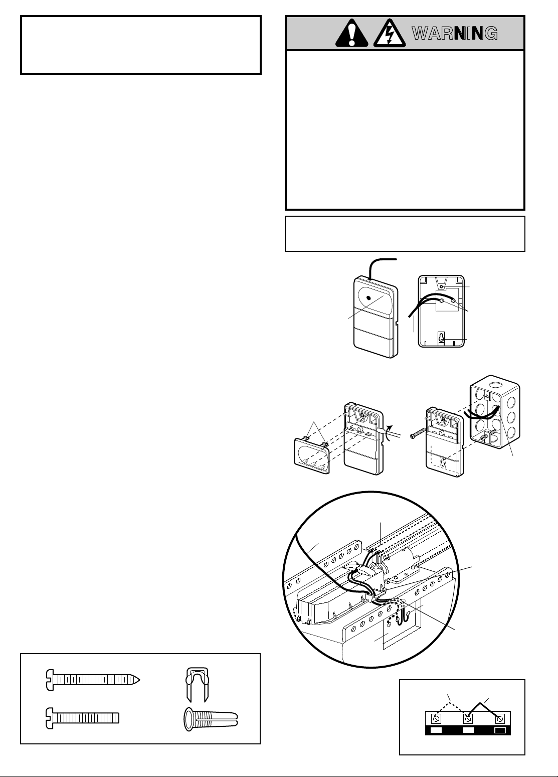
Install the Door Control and
Connect all Wiring
Locate the door control within sight of the door a t a
minimum height of 5 feet where small childr en cannot
reach, and away from all moving parts of the door and
door hardware.
The door control is typically attached directly to the wall.
If installing into drywall, drill 5/32" holes and use the
anchors provided.
home construction), Console models may be mounted to a
standard single gang box (Figure 2).
1. Strip 1/4" of insulation from one end of the bell wire
and connect it to the two screw terminals on the back of
the door control by color: white to 2 and white/red to 1.
2. Pry off cover along one side with a scr ewdriver blade
(see Figure1). Fasten with 6ABx1-1/4" self-tapping
screws (standard installation) or 6-32x1" machine
screws (pre-wired installation) as follows:
• Install bottom screw, allowing 1//8" to protrude above
wall surface.
• Position bottom of door control on screw head and
slide down to secure. Adjust screw for snug fit.
• Drill and install top screw with care to avoid cracking
plastic housing. Do not overtighten.
• Insert top tabs and snap on cover.
3. (For standard installation only) Run the bell wire up the
wall and across the ceiling to the opener. Use insulated
staples to secure the wire in several places. Be careful
not to pierce the wire with a staple, creating a short. If
your access door is near the garage door, you may run
this wire with the Safety Reversing Sensor wires along
the top of the rail. See page 18.
4. Remove the Control Center door on the right panel of
the opener to access the terminal screws.
5. Thread all wires through the opening at the base of the
drive shaft cover (see Figure 3).
6. Insert the remaining wire through the hole in the power
unit and strip 1/4" of insulation from each set of wires.
7. Connect the door control wire to the opener terminal
screws: white to 2 and white/red to 1. (See Figure 4.)
8. Separate the sensor white and white/black wires
sufficiently to connect to the opener terminal screws:
white to 2 and white/black to 3.
9. Attach the User Safety Instruction label to the wall near
the door control, and the Maintenance Instruction label
in a prominent location on the inside of the garage door.
Page 32 explains how to operate the opener using the
door control.
For pre-wired installations (as in new
Hardware Shown Actual Size
Do not connect to live electrical wiring. Connect only to 24 Volt
low voltage wires. Connection to live wires or higher v oltage
may cause serious injury from shock, burn or electrocution.
Children operating or pla ying with a garage door opener can
injure themselves or others.
The garage door could close and
cause serious injury or death.
Install the door control (or any additional push buttons) out of
the reach of c hildren and away from all moving par ts of the
door and door hardware,
but where the garage door is visible.
Do not allo w children to operate the push b utton(s) or the
remote control(s).
A moving garage door could injure someone under it.
the opener only when the door is pr operly adjusted, y ou can
see it clearly, and there are no obstructions to door travel.
Do NOT connect the power and operate the opener at
this time. See Step 9 on page 22.
Figure 3
WIRING TO
CONTROL CENTER
Drive Shaft Cover
Push wiring
through hole in chassis
(above Control Center)
and connect to opener
terminal screws
21
Figure 4
Activate
Insert wires
through
opening in
Right
Wrong
Wrong
Ground Tab
Green
Ground Screw
Ground Wire
BlackWire
Permanent Wiring
Connection
White Wire
Black
Wire
Installation Step 8
Electrical Requirements
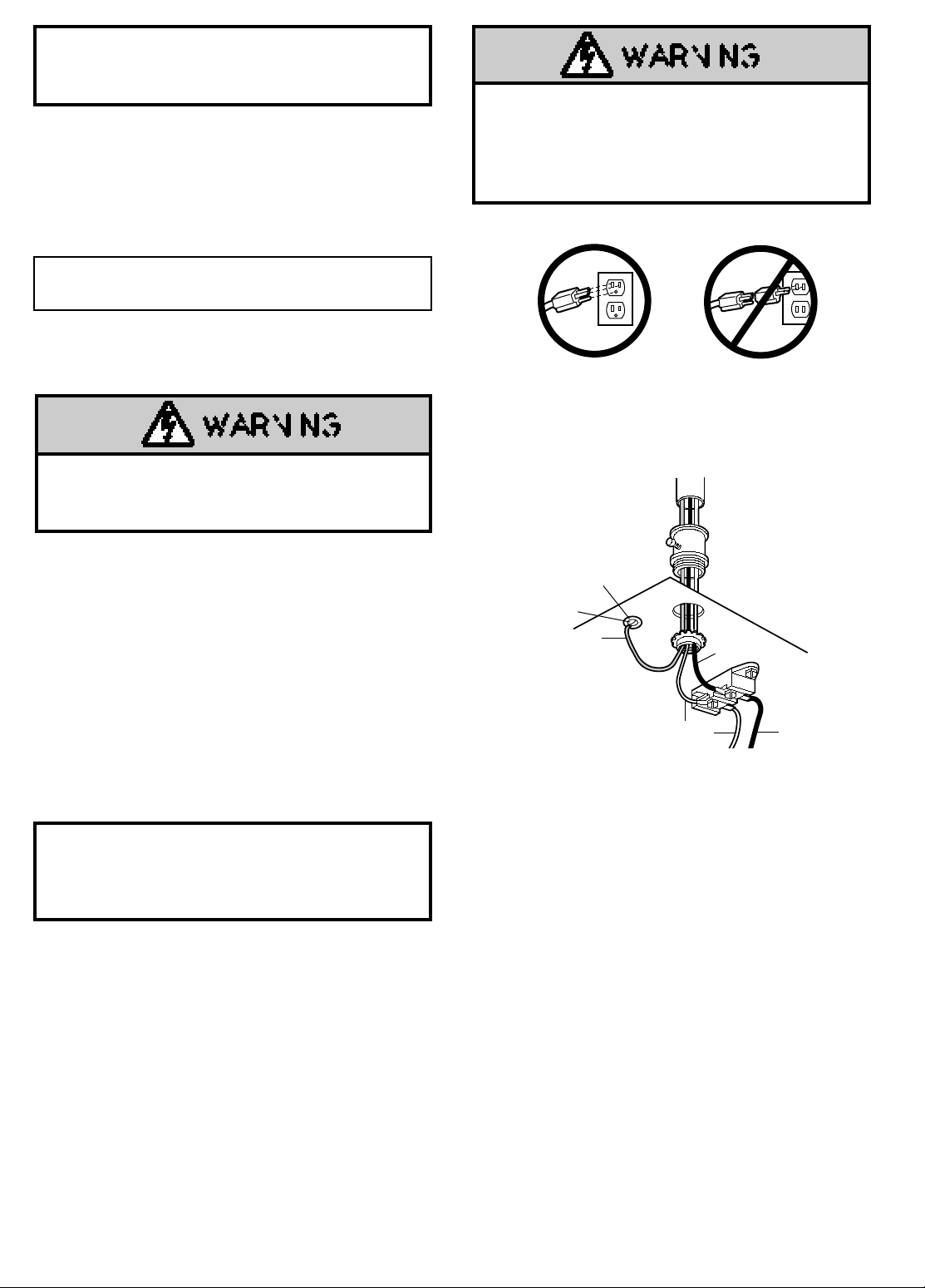
To reduce the risk of electric shock, your garage door
opener has a grounding type plug with a third grounding
pin. This plug will
If the plug doesn't fit into the outlet you have, contact a
qualified electrician to install the proper outlet.
do not run the opener until Step 9 below.
If permanent wiring is required by your local code,
refer to the following procedure:
only fit into a grounding type outlet.
To avoid installation difficulties,
To prevent electrocution or fire, installation and wiring
must be in compliance with local electrical and building
codes.
Do NOT use an extension cord, 2-wire adapter, or change
the plug in any way to make it fit your outlet.
To prevent electrocution
garage door opener
use for the permanent connection.
, remove power from the
and
from the circuit you plan to
To make a permanent connection through the 7/8" diam.
hole in the top of the opener (according to local code):
• Remove the opener cover screws and set the cover aside.
• Remove the attached 3-prong cord.
• Connect the black (line) wire to the screw on the brass
terminal; the white (neutral) wire to the screw on the
silver terminal; and the ground wire to the green
ground screw.
The opener must be grounded.
• Reinstall the cover.
Installation Step 9
Complete Safety Reversing Sensor Installation
• Plug in the opener. If your door control has a Lock
feature, be sure it is off. Green indicator lights in both the
sending and receiving eyes will glow steadily if wiring
connections and alignment are correct. If the indicator
light is off in the receiving eye (and the invisible light
beam path is not obstructed), alignment is required.
• Loosen the receiving eye wing nut to allow slight
rotation of unit. Adjust sensor vertically and/or
horizontally until the green indicator light glows with a
steady light.
• When indicator lights are glowing steadily in both units,
tighten the wing nut in the receiving eye unit.
Troubleshooting
1. If the sending eye indicator light does not glow
steadily after installation, check for:
• Electric power to the opener.
• A short in the white or white/black wires. These can
occur under staples or at screw terminal connections.
• Incorrect wiring between sensors and opener.
• An open wire (wire break).
2. If the sending eye indicator light glows steadily but
the receiving eye indicator light doesn't:
• Check alignment.
• Check for an open wire to the receiving eye.
22
Installation Step 10
Trolley
NOTICE
Overhand
Knot
Emergency
Release Handle
Rope
Overhand
Knot
Trolley
Release Arm
100 Watt Max.
Light Bulb
Bottom Lens Tab
Top Lens Tab
Top Lens Slot
Bottom Lens Slot
Light Socket
Insert Bottom Lens Tabs First
Chassis
Lens
CONTROL
CENTER
CONTROL
CENTER
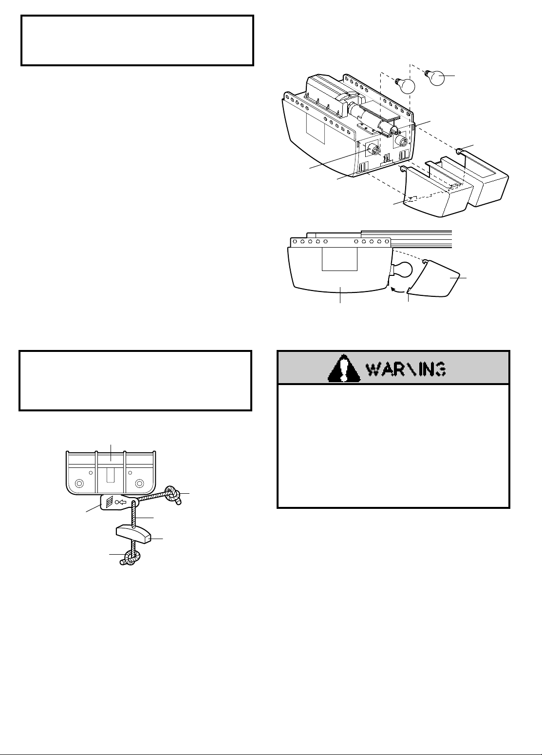
Install the Lights and Lens
• Install a 100 watt maximum light bulb in each socket.
The lights will turn ON and remain lit for
approximately 4-1/2 minutes when power is connected.
Then the lights will turn OFF.
• Insert bottom lens tabs into slots on chassis and tilt
towards chassis to engage top tabs, then drop down
gently into place.
• To remove, lift lens up and gently tilt slightly outward
and down, then pull out to clear bulbs.
avoid snapping off bottom lens tabs.
• If the bulbs burn out prematurely, replace with
standard neck Garage Door Opener bulbs. (Fluorescent
bulbs are not recommended because of possible
interference with receiver/transmitter signals.)
(See illustration.)
Use care to
Installation Step 11
Attach the Emergency Release
Rope and Handle
Do not use the red handle to pull the door open or
closed.
could fall.
The rope knot could become untied and you
Use the emergency release only to disengage
the trolley and, if possible, only when the door is closed.
Garage doors are heavy. If the door is open when the
handle is pulled, the door could close inadvertently if it is
not properly balanced. Serious injury may result to
persons under the door. Make sure the doorway is clear
of persons and obstructions before pulling handle when
door is open.
•
Thread one end of the rope through the hole in the top
of the red handle so “NOTICE” reads right side up as
shown. Secure with an overhand knot.
The knot should be at least 1" from the end of the
rope to prevent slipping.
• Thread the other end of the rope through the hole in the
release arm of the outer trolley.
• Adjust rope length so the handle is 6 feet above the
floor. Secure with an overhand knot .
If it is necessary to cut the rope, heat seal the cut end
with a match or lighter to prevent unraveling.
23
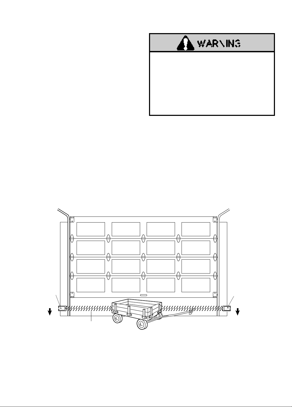
Installation Step 12
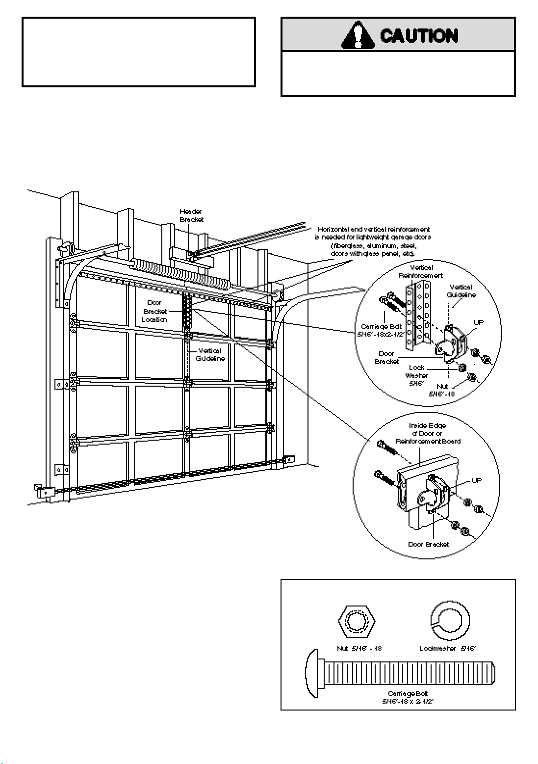
A horizontal brace should be long enough to be secured to 2 vertical supports. A vertical brace should cover the
height of the top panel.
The illustration shows one piece of angle iron as the horizontal brace. For the vertical brace, 2 pieces of angle iron
are used to create a U-shaped support. The best solution is to check with your garage door manufacturer for an
opener installation door reinforcement kit.
SECTIONAL Door Installation Procedure
Figure 1
Figure 2
Hardware Shown Actual Size
Fasten Door Bracket
Follow instructions which apply to your door type
as illustrated below or on page 25.
To prevent dama ge to steel, alumin um, fiber glass or
glass panel doors, always reinforce the inside of the door
both vertically and horizontally with an angle iron.
• Center the door bracket on the previously marked
vertical guideline used for the header bracket
installation.
stamped inside the bracket.
• Position the bracket on the face of the door within the
following limits:
A) The top edge of the bracket 2-4" below the top edge
of the door.
B) The top edge of the bracket directly below any
structural support across the top of the door.
• Mark and drill 5/16" left and right fastening holes.
Secure the bracket as shown in Figure 1 if there is
vertical reinforcement.
If your installation doesn't require vertical reinforcement
but does need top and bottom fastening holes for the door
bracket, fasten as shown in Figure 2.
Note the correct UP placement, as
24
 Loading...