

Craftsman 139.18815, 139.18859, 139.18860, 139.18855 Owner's Manual
®
Garage Door Opener
Models
139.18815 - 1/2 HP
139.18855 - 1/2 HP
139.18859 - 1/2 HP
139.18860 - 1/2 HP
For Residential Use Only
®
Owner's Manual
■ Please read this manual and the enclosed safety materials carefully!
■ Fasten the manual near the garage door after installation.
■ The door WILL NOT CLOSE unless the Safety Reversing System is connected
and properly aligned.
■ Periodic checks and adjustment of the opener are required to ensure safe
operation.
■ The model number label is located under the light lens on the left side of your
opener.
Contents Page
A review of safety alert symbols.................................2
You'll need tools..........................................................3
Safety information regarding garage door
locks and ropes........................................................3
Testing your garage door for sticking,
binding and balance..................................................3
Illustration of sectional door installation......................4
Illustration of one-piece door installation....................5
Carton inventory..........................................................6
Hardware inventory.....................................................7
Assembly section - pages 8 – 11
Assemble T-rail.........................................................8
Attach cable pulley bracket.......................................8
Install trolley ..............................................................9
Fasten T-rail to opener .............................................9
Install chain/cable ...................................................10
Attach sprocket cover.............................................10
Tighten the chain and cable...................................11
Installation section - pages 11 – 27
Installation safety instructions.................................11
Determine header bracket location
Sectional door......................................................12
One-piece door....................................................13
Install the header bracket.......................................14
Attach the T-rail to header bracket.........................15
Position the opener.................................................16
Hang the opener.....................................................17
Install the deluxe wall control .................................18
Contents Page
Install the lights and lenses ...........................................19
Attach emergency release rope and handle.................19
Electrical requirements..................................................20
Safety reversing sensor information .............................21
Install the safety reversing sensor...........................22, 23
Fasten door bracket (sectional door)............................24
Fasten door bracket (one-piece door)...........................25
Connect door arm to trolley (sectional door).................26
Connect door arm to trolley (one-piece door)...............27
Adjustment section - pages 28 – 30
Travel limit adjustments.................................................28
Force adjustments.........................................................29
Test the safety reversing sensor...................................30
Test the safety reverse system ....................................30
Operation safety instructions...........................................31
Care of your opener.........................................................31
Maintenance schedule ....................................................31
Operation of your opener ................................................32
Receiver & transmitter programming..............................33
Having a problem?....................................................34, 35
Repair parts, rail assembly..............................................36
Repair parts, installation..................................................36
Repair parts, opener assembly.......................................37
Accessories......................................................................38
Index ................................................................................39
How to order repair parts.................................................40
Maintenance agreement..................................................40
Warranty..........................................................................40
Start by reviewing these important safety alert symbols
When you see these Safety Symbols on the following pages, they will alert you to the possibility of
serious injury or death
come from something mechanical or from electric shock.
if you do not comply with the corresponding instructions. The hazard may
Read the instructions carefully.
WARNING
WARNING
Mechanical Electrical
When you see this Safety Symbol on the following pages, it will alert you to the possibility of damage
to your garage door and/or the garage door opener if you do not comply with the corresponding
instructions.
Read the instructions carefully.
CAUTION
This garage door opener is designed and tested to offer safe service provided it is installed, operated,
maintained and tested in strict accordance with the safety instructions contained in this manual.
2
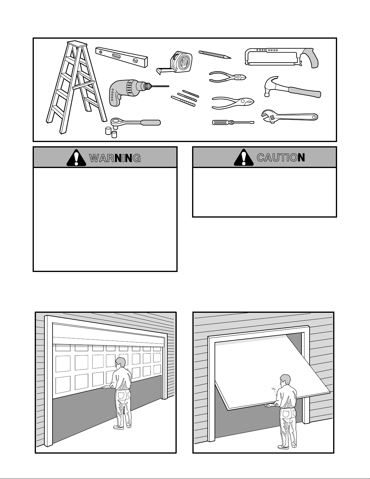
You'll Need Tools
During assembly, installation and adjustment of the opener, instructions will call for hand tools shown below.
Carpenter's
Level
Drill
Stepladder
1/2" and 7/16" Sockets
and Wrench
2
1
Tape Measure
3/16", 5/16", and
5/32" Drill Bits
WARNING
An unbalanced garage door might not reverse
when required and someone under the door
could be seriously injured or killed.
If your garage door binds, sticks or is out of
balance, call for professional garage door
service.
pulleys, brackets and their hardware, are
under extreme tension and can cause serious
injury or death.
adjust them yourself!
Ropes left on a garage door could cause
someone to become entangled and killed.
Remove all ropes connected to the door before
installing and operating the opener.
Identify the type and height of your door and any
special conditions that exist and any additional
materials that may be required by referring to the lists
on pages 4 or 5.
Garage doors, door springs, cables,
Do not try to loosen, move or
Pencil
Hack Saw
Wire Cutters
Claw Hammer
Pliers
Screwdriver
Adjustable End Wrench
CAUTION
To avoid damage to the garage door and
opener, disable locks before installing and
operating the opener. Use a wood screw or nail
to hold locks in the "open" (unlocked) position.
Operation at other than 120V 60 Hz will cause
opener malfunction and damage.
Before you begin, complete the following test to
make sure your door is balanced, and is not
sticking or binding:
• Lift the door about halfway as shown. Release the
door. It should stay in place, supported entirely by
its springs.
• Raise and lower the door to see if there is any
binding or sticking.
SECTIONAL DOOR
ONE-PIECE DOOR
3
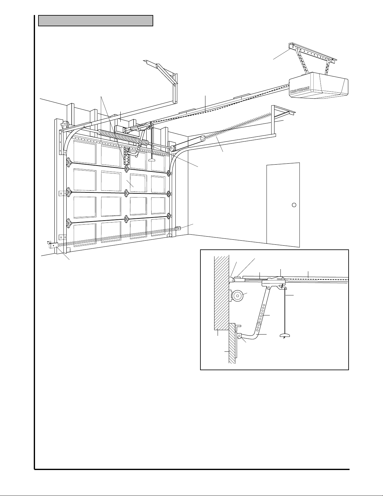
SECTIONAL Door Installation
Before you begin, survey your garage area to see whether any of the conditions below apply to your installation.
FINISHED CEILING
Support bracket &
fastening hardware
Horizontal and vertical reinforcement
is needed for lightweight garage doors
(fiberglass, steel, aluminum, door with glass panels, etc.).
See page 24 for details.
Header Wall
— — — — — — — —
Slack in Chain Tension
is Normal When
Garage Door is Closed
Extension Spring
OR
Torsion Spring
is required.
See page 17.
Door Center
Floor must be level
across width of door
Safety Reversing Sensor
Based on your particular requirements, there are
several installation steps which might call for
materials and/or hardware not included in the carton.
• Step 1, page 12 - Look at the wall or ceiling above
the garage door. The header bracket
must
be
securely fastened to structural supports.
• Step 5, page 17 - Do you have a finished ceiling in
your garage? If so, a support bracket and
additional fastening hardware may be required.
• Safety reversing sensor, page 21 - Depending
upon garage construction, wood blocks may need
to be fastened to mounting locations before
sensors are installed.
• Step 10, page 22 - Alternate floor mounting of the
safety reversing sensor will require hardware not
provided.
• Step 11, page 24 - Do you have a steel, aluminum,
fiberglass or glass panel door? If so, horizontal
and vertical reinforcement is required.
• Look at the garage door where it meets the floor. It
must close on the floor all the way across. Otherwise,
the safety reverse system may not work properly.
See page 30. Floor or door should be repaired.
Access Door
Safety
Reversing
Sensor
Header
Bracket
Header
Wall
Garage
Door
Cable Pulley
Bracket
Cable
Garage
Door
Spring
Door Bracket
Trolley
Straight
Door
Arm
Curved
Door
Arm
Closed Position
Rail Assembly
Emergency
Release
Rope & Handle
You may find it
helpful to refer
back to this page
as you proceed
with the installation
of your opener.
• An 8 foot high door will require Item No. 18754 Rail
Extension Kit. A 10 foot high door will require Item
No. 18753 Rail Extension Kit.
• The opener can be installed within 2 feet to the left
or right of the door center if there is a torsion spring
or center bearing plate in the way of the header
bracket or door bracket area. If your door has
extension springs, the opener
must
be installed
in the center of the door. See pages 12 and 24.
• Do you have an access door in addition to the
garage door? If not, Model 18752 Outside
Trolley Release is required. See page 38.
4
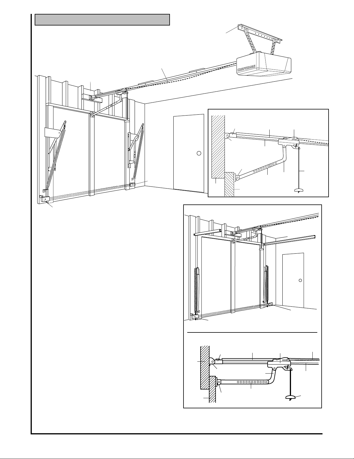
ONE-PIECE Door Installation
One-Piece Door without Track
Before you begin, survey your garage area to
see whether any of the conditions below apply
to your installation.
Slack in Chain Tension
is Normal When
Garage Door is Closed
Header
Wall
Safety
Reversing
Sensor
Gap between floor and bottom of
door must not exceed 1/4"
Safety Reversing Sensor
Based on your particular requirements, there are
several installation steps which might call for materials
and/or hardware not included in the carton.Y ou may
want to review these steps before beginning:
• Step 1, page 13 - Look at the wall or ceiling above
the garage door. The header bracket
must
be
securely fastened to structural supports.
• Step 5, page 17 - Do you have a finished ceiling in
your garage? If so, a support bracket and additional
fastening hardware (not supplied) may be required.
• Safety reversing sensor, page 21 - Depending on
garage construction, wood blocks may need to be
securely fastened to mounting locations before
sensors are installed.
• Step 10, page 22 - Alternate floor mounting of the
safety reversing sensor will require hardware that
is not provided.
• Step 11, page 25 - Generally, a one-piece door
does not require reinforcement. If your door is
lightweight, you can refer to the information
relating to sectional doors on page 24.
• Step 11, page 25 - Depending on your door's
construction, you might need additional mounting
hardware for the door bracket.
• Do you have an access door in addition to the
garage door? If not, Model 18752 Outside
Trolley Release is required. See page 38.
• The gap between the bottom of the garage door
and the floor cannot exceed 1/4". Otherwise, the
safety reverse system may not work properly. See
page 30. The floor or the door should be repaired.
FINISHED CEILING
Support bracket
& fastening hardware
may be required.
See page 17.
Closed Position
Cable
Wall
Pulley Bracket
Header
Bracket
Door Bracket
Garage
Door
Cable
T-rail
Straight
Door
Arm
Curved
Door
Arm
Trolley
Rope & Handle
Access Door
Header
One-Piece Door with Track
Slack in Chain
When Garage Door is Closed
Safety
Reversing Sensor
Floor must be level
across width of door
Closed Position
Cable
Header
Wall
Garage
Door
Pulley Bracket
Header
Bracket
Door
Bracket
Cable
Curved
Door Arm
Straight
Door
Arm
You may find it helpful to refer back to this page as you
proceed with the installation of your opener.
Tension is Normal
Access
Door
Safety
Reversing
Sensor
Trolley
T-Rail
Emergency
Release
Rope & Handle
Emergency
Release
Chain
5
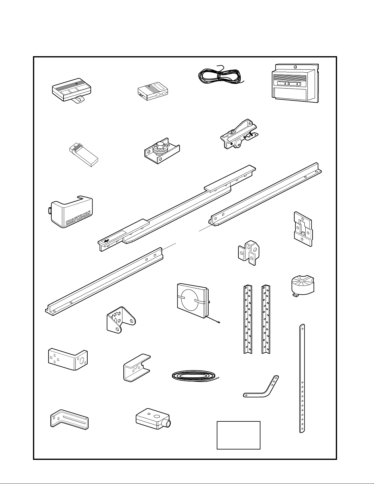
Opener Carton Inventory
Your garage door opener is packaged in two cartons which contain all parts illustrated below. If anything is
missing, carefully check the packing material. Parts may be "stuck" in the foam. Hardware for assembly and
installation is shown on page 7.
SEARS
Models 18859 & 18860
2-Conductor Bell Wire
White & White/Red
/CRAFTSMAN
LOCK
LIGHT
Three-Function Transmitter
with Visor Clip
Models 18859 & 18860
Touch Code Transmitter
Light Lens (2)
Mini Three-Function
Transmitter
Center Section
TO GARAGE DOOR
Deluxe Lighted Console
Wall Control
Trolley
Cable
Pulley Bracket
T-Rail
T-Rail
End Sections
Door Bracket Plate
Door Bracket
Safety Reversing Sensor
Mounting Bracket
With Square Holes (2)
Safety Reversing Sensor
Mounting Bracket
With Slot (2)
CEILING MOUNT ONLY
UP
Header Bracket
"C" Wrap (2)
Safety Reversing Sensor (2)
(1) Sending Eye
(1) Receiving Eye
Chain and Cable
in Dispensing Carton
2-Conductor Bell Wire
with Connector (2 Rolls)
White & White/Black
6
Hanging Brackets
Curved Door
Arm
Safety Labels
and
Literature
Sprocket Cover
Straight Door
Arm
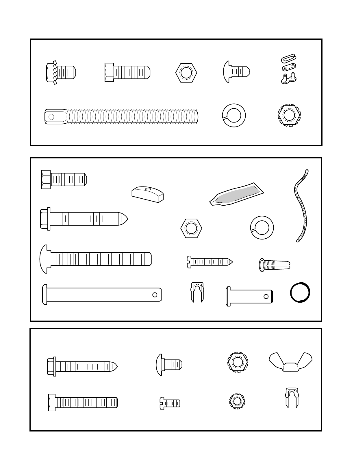
Group all hardware found in all packages contained in the rail and opener cartons into
the three kits illustrated below.
Rail Assembly Hardware Kit 41A3534
Washered Screw
5/16"-18x1/2" (2)
(mounted in opener)
Hex Screw
5/16"-18x7/8" (4)
Lag Screw
5/16"-18x1-7/8" (4)
Hex Screw
5/16"-18x7/8" (3)
Trolley
Threaded Shaft (1)
Installation Hardware Kit 41A3535
NOTICE
Handle
Nut
5/16"-18 (5)
Nut 5/16"-18 (6)
Carriage Bolts
1/4"-20x1/2" (4)
Lock Washer
5/16" (4)
Rail Grease
Lock Washer 5/16" (6)
Master Link (2)
Lock Nut
1/4"-20 (4)
Rope
Carriage Bolt
5/16"-18x2-1/2" (2)
Clevis Pin
5/16"x2-3/4" (1)
Lag Screw
1/4x1-1/2" (4)
Hex Screw
1/4-20x1-1/2" (2)
Screw
6ABx1" (2)
Insulated
Staples (10)
Safety Reversing Sensor
Installation Hardware Kit 41A4116
Carriage Bolts
1/4"-20x1/2" (4)
Screw
#10-32x3/8" (4)
5/16"x1" (2)
Lock Nut
1/4"-20 (4)
Lock Nut
#10x32 (4)
Dry Wall Anchors (2)
Clevis Pin
Ring
Fastener (3)
Wing Nut (2)
Insulated
Staples (20)
7
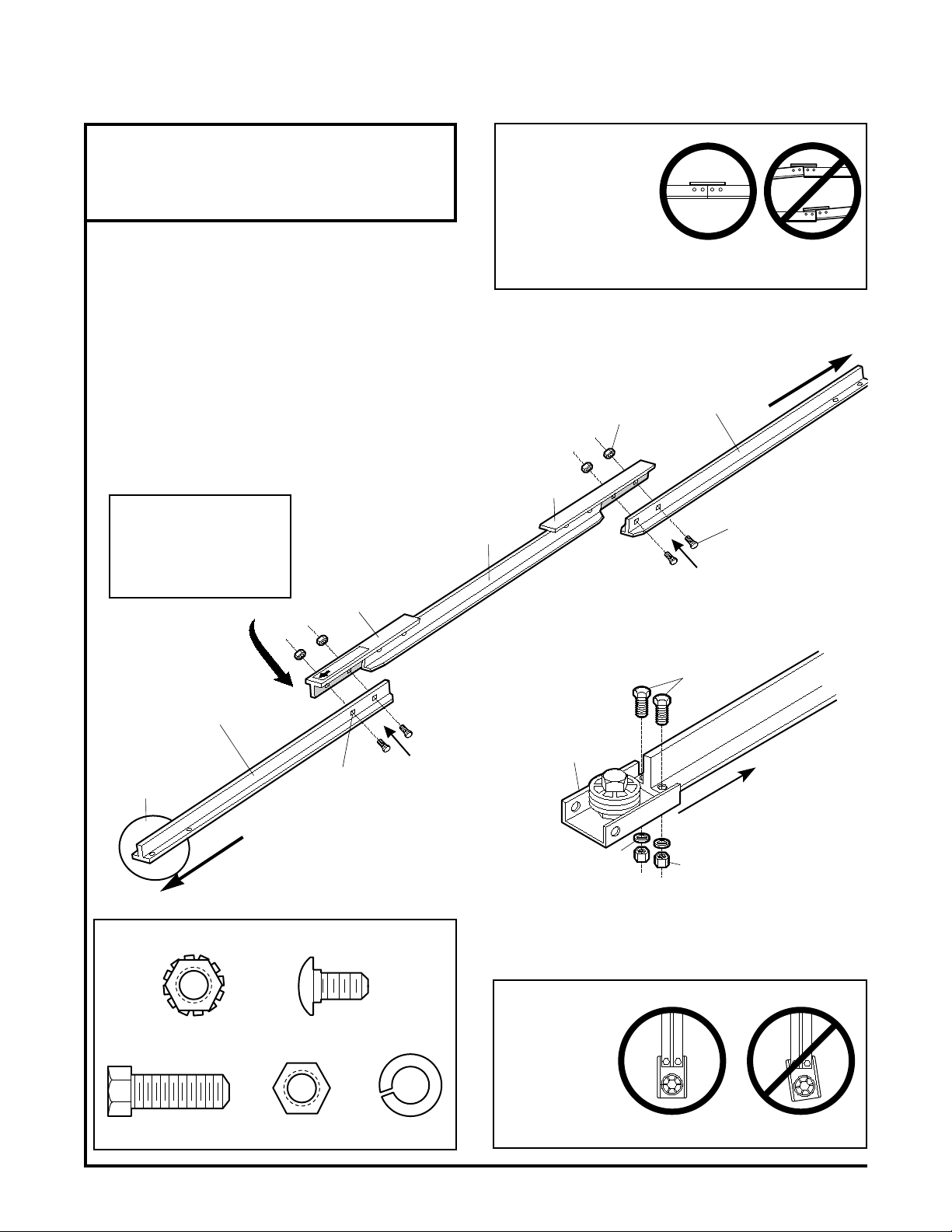
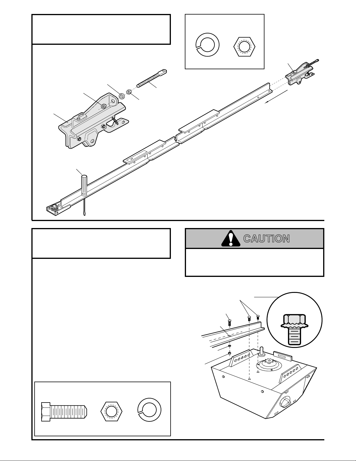
T-rail
(Center Section)
1/4'' Lock Nut
T-RAIL FRONT
(TO DOOR)
Cable pulley bracket
attaches to FRONT
END of T-rail
T-rail
(End Section)
T-RAIL BACK
(TO OPENER)
T-rail
(End Section)
Carriage Bolt
1/4"-20x1/2"
Brace
Brace
Square Carriage
Bolt Holes
TO GARAGE DOOR
Cable Pulley
Bracket
Bracket & T-rail Must Be Aligned
Lock Washer
5/16"
Nut
5/16"
Hex Screws
5/16"-18x7/8"
Cable Pulley
Bracket
Bracket & T-rail Must Be Aligned
Lock Washer
5/16"
Nut
5/16"
Assemble Tee Rai
SE
4/16/89 - 6/
Assembly Section: Pages 8 – 1 1
T o avoid installation difficulties, do not run the garage door opener until instructed to do so.
Assembly Step 1
Assemble the T-rail & Attach the Cable Pulley Bracket
• Align the 3 T-rail sections on a flat surface exactly
as shown. The end sections are identical. Make
sure the "arrow label" on the center section is
pointing toward the door.
• Insert the carriage bolts so the square bolt necks
seat in the square holes in the T-rail end sections
and pass through the round holes in T-rail center
section. Assemble lock nuts, ensure alignment and
tighten.
If T-rail is not assembled
EXACTLY as shown,
trolley will not travel
smoothly along length of
rail or it will hit against
the nuts.
Make sure bolt necks are
seated in the square
holes and rails are
aligned before you
tighten lock nuts. (See
right and wrong views).
Improper assembly can
cause jerky trolley
operation, noise and/or
nuisance door reversals.
Right Wrong
Hex Screw
5/16"-18x7/8"
Hardware Shown Actual Size
Lock Nut
1/4"-20
5/16"-18
Carriage Bolts
1/4"-20x1/2"
Nut
Lock Washer
5/16"
• Position the cable pulley bracket on the front end of the
T-rail as shown. Fasten securely with the hardware.
When tightening
the screws, be
sure to keep
bracket parallel
to the rail.
Otherwise, the
rail may bow
when opener is
operated.
Right Wrong
8
Assembly Step 2
Use Only This
Type and Size
Screw
Temporary Stop
Screwdriver
Trolley
TO GARAGE DOOR
Washered Screw
5/16"-18x1/2"
T-rail
(Back Section)
Trolley
Stop Hole
Hex Screw
5/16"-18x7/8"
Trolley
Threaded Shaft
Lock Washer
5/16"
Outer Nut
5/16"
Inner Nut
5/16"
Trolley
Install the Trolley on the T-rail
• Attach the threaded shaft to the trolley with the
lock washer and nuts as shown.
Hardware Shown
Actual Size
Lock Washer
5/16"
Nut
5/16" -18
• As a temporary stop, insert a screwdriver into the
hole in the front end of the T-rail.
• Slide the trolley assembly along the rail to the
screwdriver stop.
If trolley hits against the nut on the T-rail, the
bolts and nuts were attached from the wrong
side and must be repositioned. Review Step 1.
Assembly Step 3
Fasten the T -rail to the Opener
• Place the opener on packing material to protect
the cover. For convenience, put a support under
the cable pulley bracket.
• Remove the (2) 5/16"-18x1/2" washered screws
mounted in the top of the opener.
• Align the holes in the back section of the T-rail with
the holes in the opener.
• Fasten the rail with the (2) washered screws
Remember to use only these screws!
screws will cause serious damage to the opener.
• Insert a 5/16"-18x7/8" hex screw into the trolley
previously removed. Tighten securely.
Any other
stop hole in the T-rail as shown. Tighten securely
with a 5/16" lock washer and nut. This screw limits
trolley travel in the UP direction.
Hardware Shown Actual Size
Hex Screw
5/16"-18x7/8"
Nut
5/16"-18
Lock Washer
5/16"
CAUTION
To fasten rail, use only those screws mounted
in the top of the opener. Any other screws will
cause serious damage to the opener.
Washered Screw
T-rail
(Back Section)
Lock Washer
Hex Screw
5/16"-18x7/8"
Trolley
Stop Hole
5/16"
Nut
5/16"-18
5/16"-18x1/2"
Use Only This
Type and Size
Screw
9
Assembly Step 4
Leave Chain and Cable
Inside Dispensing
Carton to Prevent Kinking.
Dispensing Carton
Keep Chain and Cable
Taut When Dispensing
Cable
Pulley
Cable
Loop
Master
Link Bar
Master Link
Clip-On Spring
Trolley
T-rail
Pin
Pin Notch
Chain
Flat End
of Trolley
Threaded Shaft
Master
Link Cap
Master
Link Cap
Master Link
Clip-On Spring
Install Chain and Cable
In This Direction
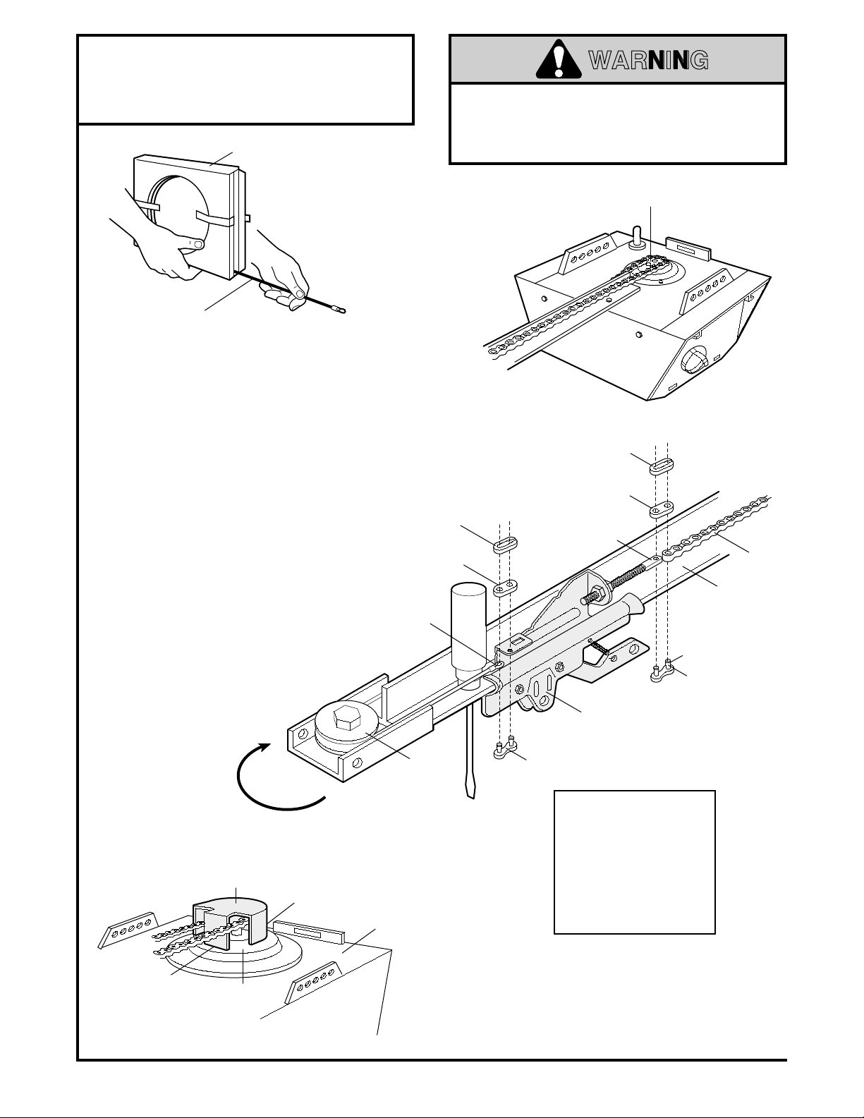
Install the Chain/Cable & Attach the Sprocket Cover
WARNING
Serious injury can result if fingers become
entangled in moving opener sprocket. Attach
sprocket cover securely. Never operate opener
while your hand is near the opener sprocket.
• Detach the cable loop from the carton and fasten it
to the trolley with a master link from the hardware
bag. See master link procedure, Figure 1.
• With the trolley against the screwdriver, dispense
the cable around the pulley.
• Proceed back around the opener sprocket,
Figure 2. Be sure sprocket teeth engage the chain.
Continue forward to the trolley threaded shaft,
Figure 3.
• Use the second master link to connect the
chain to the flat end of the shaft. Check to
make sure the chain is not twisted.
• Remove the screwdriver.
Opener
Sprocket
Figure 2
Figure 3
Front Tab Slot
Sprocket
Cover
Mounting
Plate
Back Tab Slot
Top of Opener
To attach the sprocket cover:
Figure 1
Master Link Procedure:
Push pins of master link bar
through cable loop and hole
in front end of trolley. Push
cap over pins and into
notches. Slide clip-on spring
over cap and into notches
until both pins are securely
locked.
• Insert the back tab in the opener slot. Squeeze the
cover slightly and insert the front tab in the slot on
the mounting plate.
10
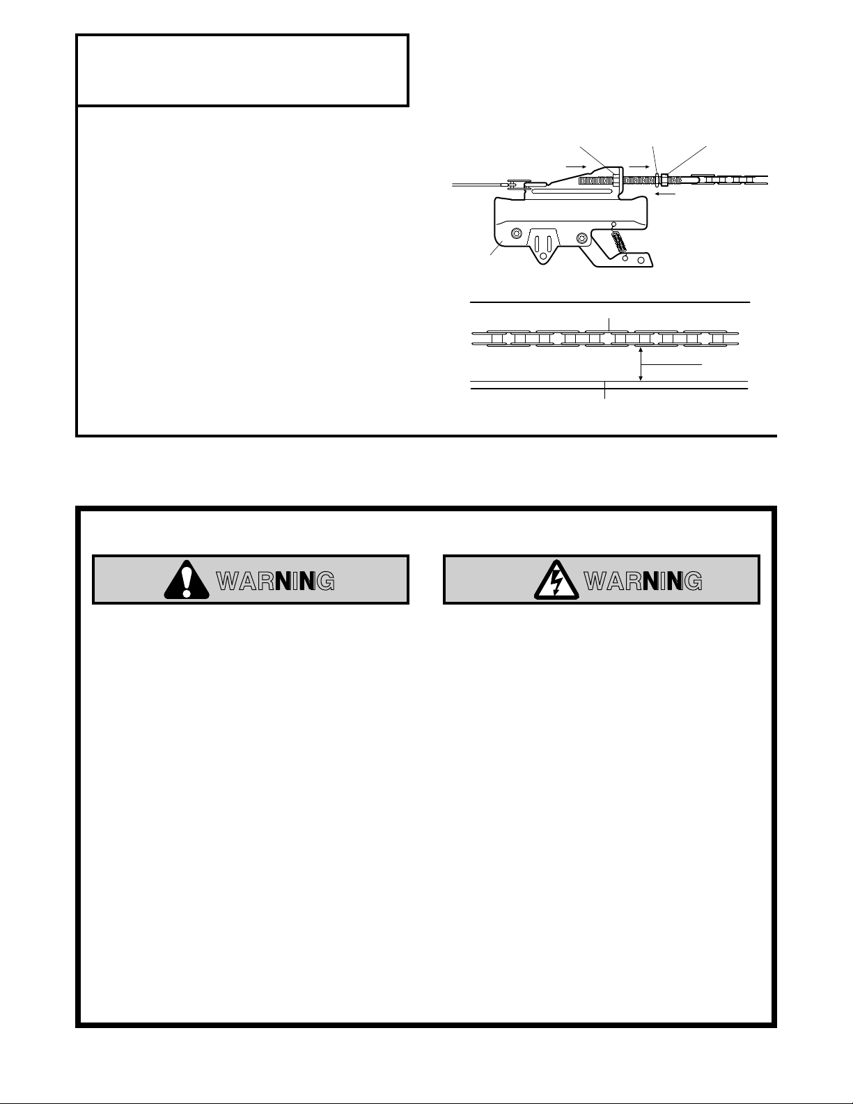
Assembly Step 5
Tighten the Chain & Cable
• Spin the inner nut and lock washer down the
threaded trolley shaft, away from the trolley.
• To tighten the chain, turn outer nut in the direction
shown. As you turn the nut, keep the chain
from twisting.
• When the chain is approximately 1/2" above the
base of the T-rail at its midpoint, re-tighten the
inner nut to secure the adjustment.
Sprocket noise can result if chain is either too
loose or too tight.
When installation is complete, you may notice some
chain droop with the door closed. This is normal. If
the chain returns to the position shown when the
door is open,
NOTE: During future maintenance,
the emergency release handle to disconnect
trolley before adjusting chain.
do not re-adjust the chain.
ALWAYS
pull
Outer Nut
To Tighten Outer Nut
Trolley
Chain
Base of T-rail
Lock
Washer
Inner Nut
To Tighten
Inner Nut
1/2"
You have now finished assembling your garage door opener. Please read the following
warnings before proceeding to the installation section:
IMPORTANT INSTALLATION INSTRUCTIONS
WARNING
WARNING
To reduce the risk of severe injury or death to persons:
1. READ AND FOLLOW ALL INSTALLATION INSTRUCTIONS
2. Install only on a properly balanced and lubricated garage door.
could result in severe injury or death.
must be made by a professional service person before installing opener.
3. Disable all locks and remove all ropes connected to the garage door before installing the opener.
Repairs to cables, spring assemblies and other hardware
Ropes connected to a garage door can cause entanglement and death.
4. If possible, install door opener 7 feet or more above floor with the manual release handle
mounted 6 feet above the floor.
5. Do not connect the opener to power source until instructed to do so.
6. Locate the Wall Control within sight of the door at a minimum height of 5 feet where small
children cannot reach and away from all moving parts of the door.
7. Install the User Safety Instruction Label on the wall adjacent to the control button and the
Maintenance Instruction Label in a prominent location on the inside of the garage door.
An improperly balanced door
8. Upon completion of the installation, the door must reverse when it comes in contact with a 2x4
laid flat on the floor.
9. Do not wear watches, rings or loose clothing while installing or servicing an opener. Jewelry or
loose clothing can be caught in the mechanism of the garage door or the opener.
11
Vertical
Guideline
Finished
Ceiling
Vertical
Guideline
Header
Wall
2x4
Structural
Supports
Installation Section: Pages 12 – 27
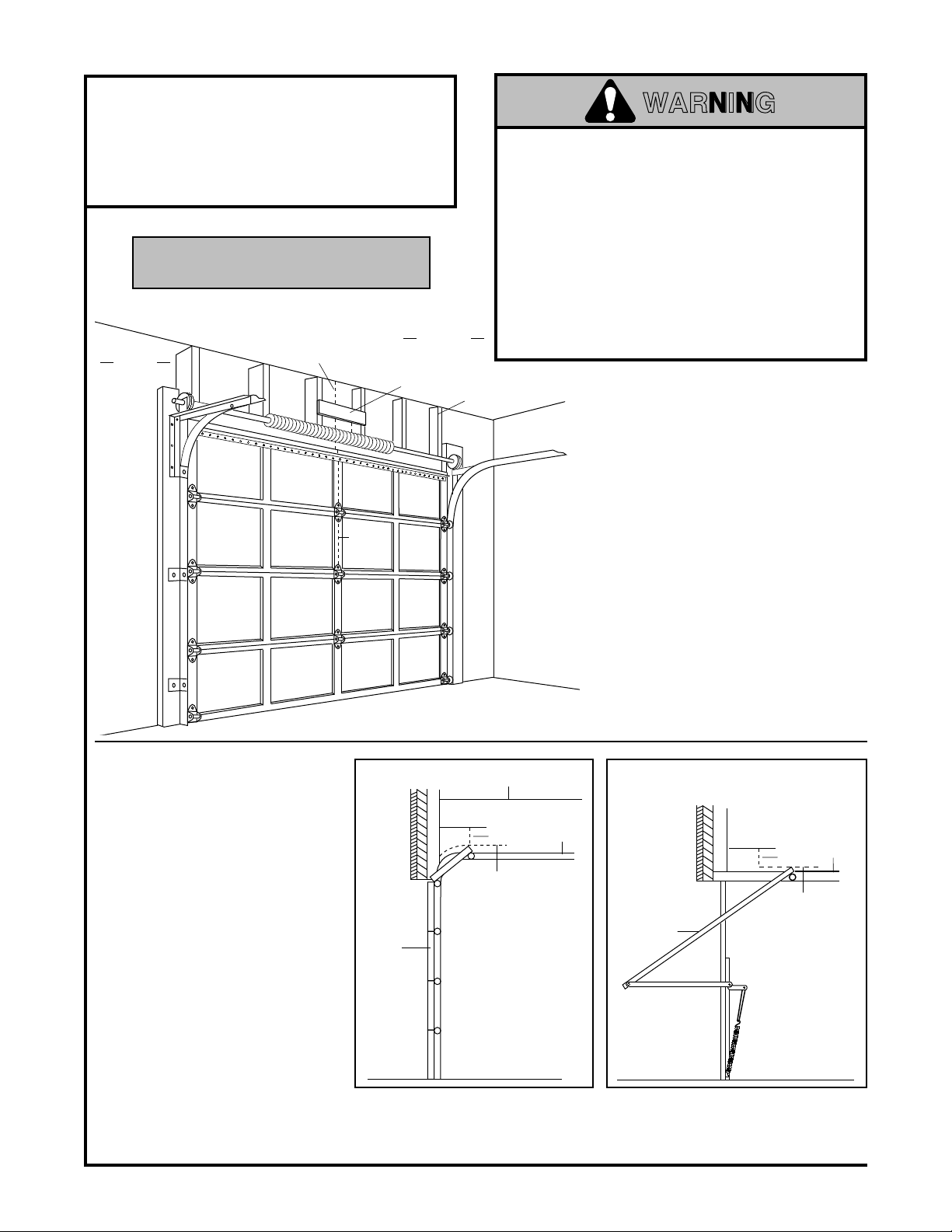
Installation Step 1
Determine Header Bracket Location
Installation procedures vary according to
garage door types. Follow the instructions
which apply to your door
SECTIONAL Door and
ONE-PIECE Door With Track
WARNING
If the header bracket is not rigidly fastened to
a structural support on the header wall or
ceiling, the safety reverse system may not
work properly (see page 30).
not reverse when required, and could cause
serious injury or death.
The garage door springs, cables, pulleys,
brackets and their hardware are under extreme
tension.
Do not attempt to loosen, move or
adjust them yourself. Serious personal injury
or death could result.
service.
• Close the door and mark the inside
vertical centerline of the garage door.
• Extend the line onto the header wall
above the door.
Remember, you can fasten the
header bracket within 2 feet to the
left or right of the door center
a torsion spring or center bearing
plate is in the way; or you can attach
it to the ceiling (refer to page 14)
when clearance is minimal.
If you need to install the header bracket
on a 2x4 (on wall or ceiling), use lag
screws (not supplied) to securely fasten
the 2x4 to structural supports.
The door might
Call for garage door
only
if
• Open your door to the highest
point of travel as shown. Draw
an intersecting horizontal line
on the header wall 2" above
the high point. This height will
provide travel clearance for the
top edge of the door.
Door clearance brackets are
available for sectional doors
when headroom clearance is
less than 2". See accessory
page 38.
Proceed to Step 2, page 14.
Door
Sectional door
with curved track
Ceiling
Header
Wall
2"
Highest Point
of Travel
12
Track
Header
Highest Point
Door
One-piece door with
horizontal track
Wall
2"
of Travel
Track
 Loading...