

Craftsman 12458833 Owner’s Manual

Operator’s Manual
10″
CONTRACTOR TABLE SAW
Model No.
124.58833
Safety
Unpacking
CAUTION:
Read and follow all Safety
Rules and Operating
Instructions before First Use of
this Product. Keep this Manual
with Tool.
Sears Brands Management Corp., Homan Estates, IL 60179 U.S.A
www.craftsman.com
Assembly
Operation
Maintenance
Parts List
Español

TABLE OF CONTENTS
Warranty .........................................................................................2
Safety Rules.................................................................................2-5
Unpacking.......................................................................................5
Assembly....................................................................................6-13
Installation................................................................................13-14
Operation.................................................................................14-20
Maintenance.................................................................................20
Troubleshooting............................................................................21
Parts Illustrations, Lists and Notes...........................................22-30
Español.........................................................................................31
WARRANTY
CRAFTSMAN LIMITED WARRANTY
FOR ONE YEAR from the date of sale this product is warranted
against defects in material or workmanship.
WITH PROOF OF SALE a defective product will receive free
repair. If the product cannot be repaired it will be replaced free of
charge.
For warranty coverage details to obtain free repair, visit the web
page: www.craftsman.com/warranty
This warranty does not cover the blade, which is an expendable
part that can wear out from normal use within the warranty period.
This warranty applies for only 90 days from the date of sale if this
product is ever used while providing commercial services or if
rented to another person.
This warranty gives you specific legal rights, and you may also
have other rights which vary from state to state.
Sears Brands Management Corporation, Homan Estates, IL
60179
For Questions/Comments or Technical Assistance-Please call
Customer Service; 1-(877) 866-8392 (M-F 8:30AM-5PM EST.)
SAFETY RULES
WARNING:
precautions before operating tool.
PROPOSITION 65 WARNING
WARNING:
products can expose you to wood dust, a substance known to the
State of California to cause cancer. Avoid inhaling wood dust or
use a dust mask or other safeguards for personal protection. For
more information go to
Your risk from these exposures vary, depending on how often you
do this type of work. To reduce your exposure to dust: work in a
well ventilated area and work with approved safety equipment.
Always wear OSHA/NIOSH approved, properly tting face mask or
respirator when using such tools.
CAUTION:
dened in this manual — even if you are familiar with use of
this or similar tools. Remember that being careless for even a
fraction of a second can result in severe personal injury.
BE PREPARED FOR THE JOB
• Wear proper apparel. Do not wear loose clothing, gloves,
neckties, rings, bracelets or other jewelry which may get
caught in moving parts of machine.
• Wear protective hair covering to contain long hair.
• Wear safety shoes with non-slip soles.
• Wear face mask or dust mask if operation is dusty.
For your own safety, read all of the instructions and
Drilling, sawing, sanding or machining wood
www.P65Warnings.ca.gov/wood.
Always follow proper operating procedures as
2
• Wear safety glasses complying with United States ANSI
Z87.1. Everyday glasses have only impact resistant lenses.
They are
• Be alert and think clearly. Never operate power tools
when tired, intoxicated or when taking medications
that cause drowsiness.
PREPARE WORK AREA FOR JOB
• Keep work area clean. Cluttered work areas invite
accidents.
• Do not use power tools in dangerous environments. Do not
use power tools in damp or wet locations. Do not expose
power tools to rain.
• Work area should be properly lighted.
• Keep visitors at a safe distance from work area.
• Keep children out of workplace. Make workshop childproof.
Use padlocks, master switches or remove switch keys to
prevent any unintentional use of power tools.
• Keep power cords from coming in contact with sharp
objects, oil, grease and hot surfaces.
TOOL SHOULD BE MAINTAINED
• Always unplug tool prior to inspection.
• Consult manual for specic maintaining and adjusting
procedures.
• Keep tool lubricated and clean for safest operation.
• Remove adjusting tools. Form habit of checking to see that
adjusting tools are removed before switching machine on.
• Keep all parts in working order. Check to determine that
the guard or other parts will operate properly and perform
their intended function.
• Check for damaged parts. Check for alignment of moving
parts, binding, breakage, mounting and any other condition
that may aect a tool’s operation.
• A guard or other part that is damaged should be properly
repaired or replaced. Do not perform makeshift repairs.
(Use parts list provided to order replacement parts.)
• Maintain proper adjustment of rip fence and blade guard.
• Never adjust saw while running. Disconnect power to avoid
accidental start-up.
• Have damaged or worn power cords replaced immediately.
• Keep blade sharp for ecient and safest operation.
KNOW HOW TO USE THE TOOL
• Use right tool for the job. Do not force tool or attachment to
do a job for which it was not designed.
• Disconnect tool when changing blade.
• Avoid accidental start-up. Make sure that the tool is in the
“o” position before plugging in, turning on safety
disconnect or activating breakers.
• Do not force tool. It will work most eciently at the rate for
which it was designed.
• Keep hands away from blade and moving parts and cutting
surfaces.
• Never leave tool running unattended. Turn the power o
and do not leave tool until it comes to a complete stop.
• Do not overreach. Keep proper footing and balance.
• Never stand on tool. Serious injury could occur if tool is
tipped or if blade is unintentionally contacted.
• Know your tool. Learn the tool’s operation, application and
specic limitations.
NOT
safety glasses.

• Handle workpiece correctly. Press rmly against table.
Protect hands from possible injury.
• Turn machine o if it jams. Blade jams when it digs too
deeply into workpiece. (Motor force keeps it stuck in the
work.)
• Feed work into the blade only as recommended in
“Operation.”
WARNING:
until it is completely assembled and installed according to
instructions.
STABILITY OF SAW
If there is any tendency for the saw to tip over or move during
certain cutting operations, such as cutting extremely heavy
panels or long heavy boards, the saw should be bolted down.
If you attach any kind of extensions over 24" wide to either
end of the saw, make sure you either bolt the saw to the oor,
as appropriate, or support the outer end of the extension
from the bench or oor, as appropriate.
LOCATION
The saw should be positioned so neither the operator nor a
casual observer is forced to stand in line with the saw blade.
KICKBACKS
A kickback occurs during a rip-type operation when a part or
all of workpiece is thrown back violently toward operator.
Keep your face and body to one side of the saw blade, out of
line with a possible kickback.
Kickbacks and possible injury from them can usually be
avoided by:
• Maintaining rip fence parallel to saw blade.
• Keeping saw blade sharp. Replace or sharpen anti-
kickback pawls when points become dull.
• Keeping saw blade guard, spreader, and anti-kickback
pawls in place and operating properly. The spreader must
be in alignment with the saw blade and the pawls must
stop a kickback once it has started. Check their action
before ripping.
• Not ripping work that is twisted or warped or does not
have a straight edge to guide along the rip fence.
• Not releasing work until you have pushed it all the way
past the saw blade.
• Using a push stick for ripping widths less than 6 inches.
• Not conning the cuto piece when ripping or crosscutting.
PROTECTION: EYES, HANDS, FACE, BODY, EARS
• If any part of your saw is missing, malfunctioning, or has
been damaged or broken (such as the motor switch,
electronic controls, other operating control, a safety device
or power cord), cease operating immediately until the
particular part is properly repaired or replaced.
• Wear safety goggles that comply with United States ANSI
Z87.1 and a face shield or dust mask if operation is dusty.
Wear ear plugs or mus during extended periods of
operation.
• Small loose pieces of wood or other objects that contact
the rear of the revolving blade can be thrown back at the
operator at excessive speed. This can usually be avoided
by keeping the guard and spreader in place for all
thru-sawing operations (sawing entirely thru work) and
by removing all loose pieces from the table with a long stick
of wood immediately after they are cut o.
For your own safety, do not operate your saw
• Use extra caution when the guard assembly is removed for
resawing, dadoing, or rabbeting—replace guard as soon
as that operation is completed.
• Never turn the saw ON before clearing the table of all
tools, wood scraps, etc., except the workpiece and related
feed or support devices for the operation planned.
• Never place your face or body in line with the cutting tool.
• Never place your ngers or hands in path of saw blade or
other cutting tool.
• For rip or rip-type cuts, the following end of a workpiece to
which a push stick or push board is applied must be
square (perpendicular to the fence) in order that feed
pressure applied to the workpiece by the push stick or
block does not cause the workpiece to come away from
the fence, and possibly cause a kickback.
• During rip and rip-type cuts, workpiece must be held down
on table and against fence with a push stick, push block,
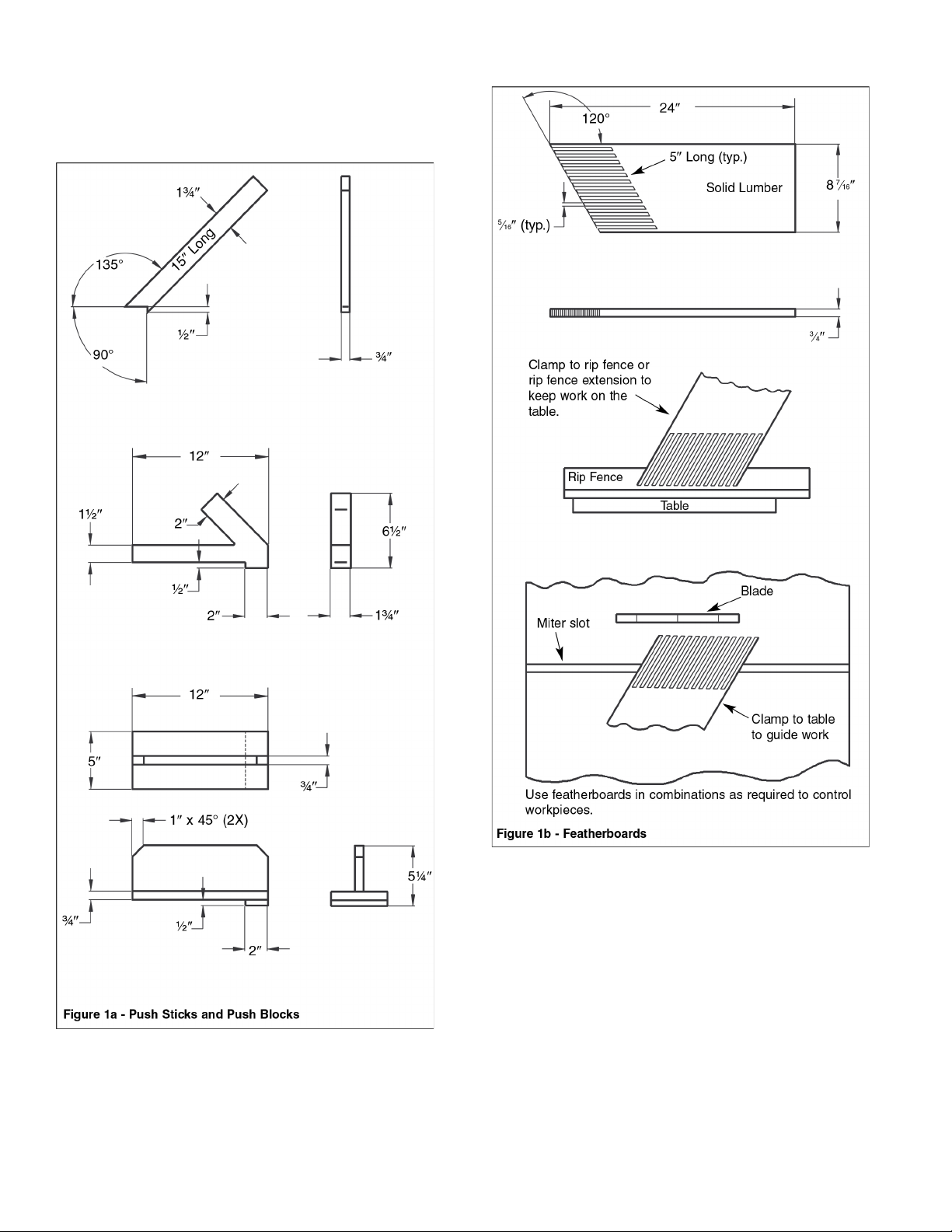
or featherboards, as applicable (see Figures 1a and 1b,
page 4).
The push stick and push block examples shown on page
4 are useful for keeping hands and ngers away from saw
blade during ripping, rabbeting and dadoing. Apply downward pressure and push workpiece through the cut and past
the blades. Several other congurations may be suitable for
safe operation.
Featherboards are used to keep the work in contact with the
rip fence or table during the cutting operation. Use of featherboards can help to prevent kickbacks and binding. Feather-
boards should be used for all “non thru-sawing” operations.
• Never reach in back of the cutting tool with either hand to
hold down or support the workpiece, remove wood scraps,
or for any other reason. Avoid awkward operations and
hand positions where a sudden slip could cause ngers or
hand to move into a saw blade or other cutting tool.
• Do not perform layout, assembly, or setup work on the
table while the cutting tool is rotating.
• Do not perform any operation freehand—always use either
rip fence or miter gauge to position and guide the work.
• Never use the rip fence when cross-cutting or the miter
gauge when ripping. Do not use rip fence as a length stop.
Never hold onto or touch free-end of workpiece or a free-
piece that is cut o, while power is ON and/or saw blade is
rotating.
• Shut the saw OFF and disconnect power source when
removing the table insert, changing the cutting tool,
removing or replacing the blade guard, or making adjust
ments.
• Provide adequate support to the rear and sides of the saw
table for wide or long workpieces.
• Plastic and composition materials (like hardboard) may be
cut on your saw. However, since these are usually quite
hard and slippery, the anti-kickback pawls may not stop a
kickback. Therefore, be especially attentive to following
proper setup and cutting procedures for ripping. Do not
stand, or permit anyone else to stand, in line with a poten-
tial kickback.
• If you stall or jam the saw blade in the workpiece, turn saw
OFF and remove the workpiece from the saw blade.
Check to see if the saw blade is parallel to the miter
gauge grooves and if the spreader is in proper alignment
with the saw blade. If ripping at the time, check to see if
the rip fence is parallel with the saw blade. Readjust as
required.
3
• Do not remove small pieces of cuto material that may
become trapped inside the blade guard while the saw is
running. This could endanger your hands or cause kick
back. Turn saw OFF and wait until blade stops.
• Use extra care when ripping wood with twisted grain or
wood that is twisted or bowed—it may rock on table and
pinch saw blade.
• Never use grinding wheels, abrasive cuto wheels, friction
wheels (metal slitting blades), wire wheels or bung
wheels.
KNOW YOUR CUTTING TOOLS
• Dull, gummy, improperly sharpened or set cutting tools can
cause material to stick, jam, stall saw, or kickback at
operator. Minimize potential injury by proper care and
machine maintenance.
WARNING:
without rst turning saw OFF.
Never attempt to free a stalled saw blade
USE ONLY ACCESSORIES DESIGNED FOR SAW
• Crosscutting operations are worked more conveniently and
with greater safety if an auxiliary wood facing is attached
to miter gauge using holes provided. However, facing must
not interfere with proper functioning of saw blade guard.
• Make sure the top of the arbor or cutting tool rotates
toward you when standing in normal operating position.
Also make sure the cutting tool, blade ange and arbor
nut are installed properly. Keep the cutting tool as low as
possible for the operation being performed. Keep all
guards in place whenever possible.
• Do not use any blade or other cutting tool marked for
operating speed less than 4000 RPM. Never use a cutting
tool larger in diameter than diameter for which saw was
designed. For greatest safety and eciency when ripping,
use maximum diameter blade for which saw is designed,
since under these conditions spreader is nearest the
blade.
4
• Adjust table inserts ush with table top. Never operate saw
unless proper insert is installed.
• Never feed material into the cutting tool from the rear of
the saw. An accident and serious injury could result.
Hardware Bag #1 (For extension table assembly)
M10X25 Socket head bolt (6)
10mm Lock washer (6)
10mm Flat washer (6)
THINK SAFETY
Safety is a combination of operator common sense and alertness at all times when the saw is being used.
Never use another person as a substitute for a table extension, or as additional support for a workpiece that is longer or
wider than basic saw table, or to assist in feeding, supporting
or pulling the workpiece.
Do not pull the workpiece through the saw blade—position
your body at the infeed side of the guard; start and complete
the cut from that same side. This will require added table
support for long or wide workpieces that extend beyond the
length or width of the saw table.
CAUTION:
of your saw.
Follow safety instructions that appear on the front
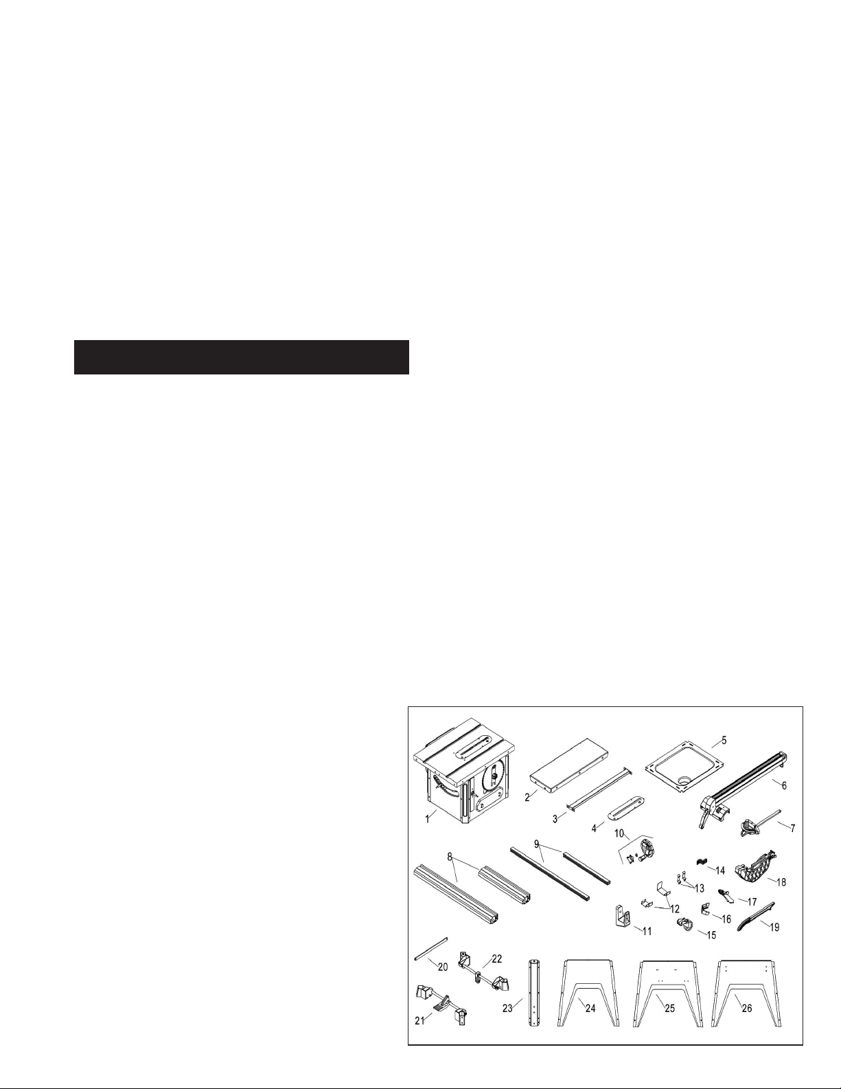
UNPACKING
Refer to Figure 2.
• Open shipping box. Remove all parts, except saw body,
from both styrofoam packing bases and set parts and top
base safely aside. Remove the dust chute from the saw
cabinet.
• Use utility knife to cut down the four corners of the shipping
box, allowing cardboard sides to lay on oor and fully
exposing the styrofoam packing base.
• Cut away enough styrofoam from motor cover side of
packing base so that, with the aid of an assistant, you can
slide the saw body from the base onto cardboard. Saw
table will remain on cardboard until instructed in Assembly
section to turn saw body upright onto leg base.
CAUTION:
Use this manual to order replacement parts.
Check for shipping damage or missing parts. If any parts are
damaged or missing, call 1-888-331-4569 for replacement.
The table saw body comes assembled as one unit. Additional
parts which need to be fastened to the saw should be located
and accounted for before assembling:
1. Table saw
2. Extension table (2)
3. Brace
4. Table insert
5. Dust chute
6. Rip fence assembly
7. Miter gauge assembly
8. Front rail (2)
9. Rear rail (2)
10. Handwheel with knob (2)
11. Rip fence storage hooks (2)
12. Blade guard storage hooks (2)
13. Push stick storage hooks (2)
14. Line cord wrap hooks (2)
15. Caster (4)
16. Foot (4)
17. Anti-kickback pawl assembly
18. Blade guard assembly
19. Push stick
20. Link plate
21. Front caster support assembly
22. Rear caster support assembly
23. Corner support (4)
24. Base panel “A” (2)
25. Base panel “B”
26. Base panel “C”
Do not attempt assembly if parts are missing.
Hardware Bag #2 (For guide rail and brace assembly)
M8X30 Hex head bolt (16)
M8X16 Hex head bolt (4)
8mm Lock washer (20)
8mm Flat washer (20)
M8 Hex nut (16)
M8 Acorn hex nut (4)
Hardware Bag #3 (For switch assembly)
M6X16 Hex head bolt (2)
6mm Flat washer (2)
6mm Lock washer (2)
M6 Hex nut (2)
Hardware Bag #4
M10X25 Socket head bolt (4)
10mm Lock washer (4)
10mm Flat washer (4)
(For assembling stand to main machine)
-----------------------------------------------------M8X16 Socket pan head screw (8)
(For assembling caster supports to corner support)
------------------------------------------------------------------M6X12 Socket pan head screw (24)
(For assembling corner support to base panel)
-------------------------------------------------------------M6X20 Socket pan head screw (4)
6mm Flat washer (4)
M6 Hex nut (4)
(For assembling fence storage hooks and line cord hooks)
----------------------------------------------------------------------------M4X8 Pan head screw (8)
(For assembling push stick storage and blade guard storage
hooks)
4mm Flat washer (8)
Hardware Bag #5
10/13mm Open end wrench
4mm Hex wrench 6mm Hex wrench
5mm Hex wrench 8mm Hex wrench
Figure 2 - Unpacking
5

ASSEMBLY
ASSEMBLE MOBILE BASE PANELS
Refer to Figure 5.
CAUTION:
Do not attempt assembly if parts are missing.
Use this manual to order replacement parts. Be certain all
parts are clean and free of shipping preservative. Also, completely remove all parts of packing. Saw cabinet should be
assembled directly on the oor.
SAW INSTALLATION
Positioning the saw on a level surface will improve stability
and accuracy and prevent warpage and failure of cast components and welds.
WARNING:
Make certain that the saw is disconnected from
the power source.
INSTALL HANDWHEELS
Refer to Figure 3.
• Remove saw cabinet and place upside down on cardboard
box or cardboard on oor.
• Place one of the handwheels onto the blade raise/lower
shaft located on the front of the cabinet. Align the groove
in the back of the handwheel with the pin.
• Thread the washer and locking knob onto the threaded end
of the shaft. Do not overtighten or handwheel will not turn.
• Repeat the steps above to assemble the remaining hand
wheel and locking knob onto the blade tilt shaft located on
the side of the cabinet.
Tools Required:
Hardware Required:
4mm Hex Wrench.
Twenty-four M6 x 12 socket pan head
screws (Hardware bag #4).
• Attach a corner support to each front panel edge with three
M6 x 12 socket pan head screws.
NOTE:
Place the panel edges INSIDE the corner support
surfaces.
NOTE:
Front panel and rear panel are both stamped ‘A’.
Front panel has warning label.
• Repeat above step for the rear panel.
Figure 5
Panel B (left)
M6 x 12 Socket
Pan Head
Screws (x24)
Panel A (rear)
Figure 3
Handwheel
Flat Washer
Locking Knob
Cardboard
REMOVE PACKING MATERIAL
Refer to Figure 4.
• Use the blade height handwheel to lower the motor.
• Remove the packing material from behind the motor.
• Return motor to the raised position.
Figure 4
Panel C (right)
Panel A (front)
• Turn all panels upside down to perform base assembly.
• Attach one corner of left panel (stamped ‘B’) to front panel
A.
• Attach the other corner of left panel B to rear panel A.
• Repeat above two steps for attachment of right panel
(stamped ‘C’).
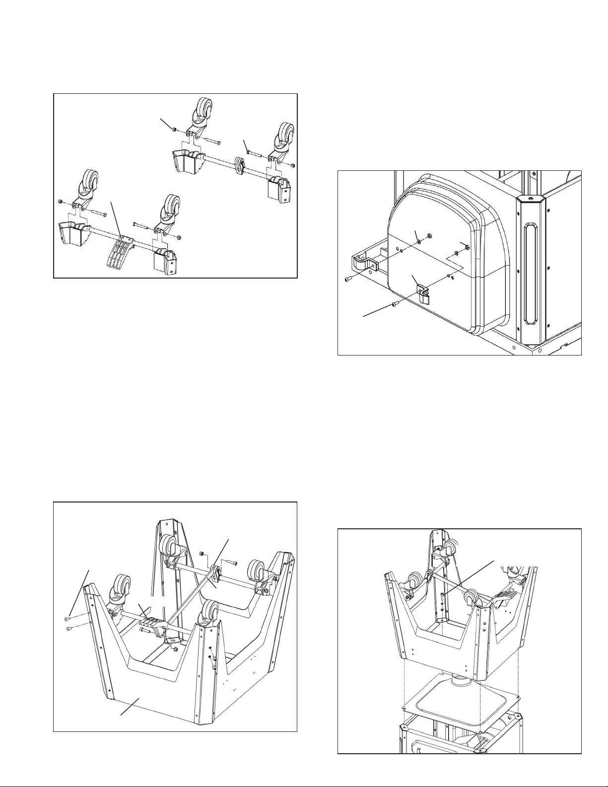
ASSEMBLE CASTER SETS
Refer to Figures 6 & 7.
Tools Required:
One 6mm Hex wrench and one 13mm
Open End or Adjustable Wrenches.
• Remove casters (4), link plate and caster supports (2) from
carton.
Figure 6
Casters
Packing Material
Caster Support (rear)
Link Plate
Caster Support (front)
6
• Loosen and remove the pre-installed bolts and hex nuts
from the brackets (see Figure 7).
• Rotate foot pedal bar so that foot pedal is pointing down
towards the oor.
• Place casters onto the brackets and secure in position with
bolts and hex nuts provided.
Figure 7
Hex Nut
Bolt
Foot Pedal
ATTACH CASTER SETS TO BASE
Refer to Figure 8.
ATTACH CORD WRAP HOOKS
Refer to Figure 9.
Tools Required:
Hex wrench 4mm and 10mm open end
wrench.
Hardware Required:
Two M6 x 20 socket pan head screws,
two M6 at washers and two M6 hex nuts (Hardware bag
#4).
• Place cord wrap hook into position on motor housing.
• Insert washer onto bolt. Insert bolt through hole and thread
nut onto bolt end on inside of housing.
• Repeat for other hook.
Figure 9
Flat Washer
M6
Hex Nut
M6
Cord Wrap
Hook
Tools Required:
Hex wrench 5mm, Hex wrench 6mm and
13mm Open end wrench.
Hardware Required:
Eight M8 x 16 socket pan head screws
(Hardware bag #4).
• Attach the foot pedal caster set to the two front corner
supports using four M8 x 16 socket pan head screws.
• Attach the link block caster set to the two rear corner
supports.
• Remove the socket head bolt and hex nut from the foot
pedal, insert the link plate into the slot of foot pedal and
secure in place with the socket bolt and hex nut.
• Remove the socket head bolt and hex nut from the link
block of rear caster set, insert the link plate into the slot of
link block and secure in place with the socket bolt and hex
nut.
Figure 8
Link Block
M8 x 16 Socket
Pan Head Screws
(8)
Link Plate
Foot Pedal
M6 x16 Socket
Pan Head
Screw
ATTACH BASE TO CABINET
Refer to Figure 10.
Tools Required:
Hardware Required:
8mm Hex Wrench.
Four M10 x 25 socket head bolts, four
M10 lock washers and four M10 at washers (Hardware bag
#4).
• Place dust chute over the cabinet as shown. Make sure
the holes in the corners are aligned with the slots in the
dust chute.
• Place the base assembly over the dust chute and secure
the base assembly to the cabinet using the at washers,
lock washers and bolts.
• Secure all fasteners in the base assembly fully tight.
Figure 10
Bolt/Lock Washer/Flat
Washer (x4)
Panel A (front)
Dust Chute
7
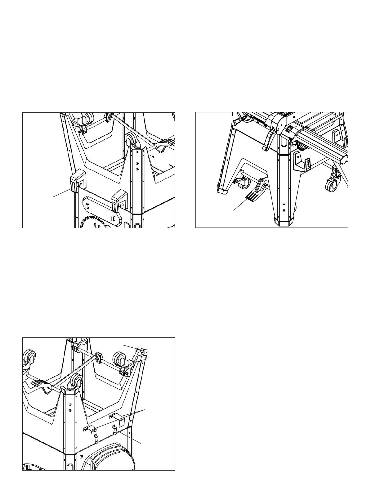
ATTACH RIP FENCE STORAGE BRACKETS
Refer to Figure 11.
Tools Required:
4mm Hex wrench and 10mm Open end
wrench.
Hardware Required:
Two M6 x 16 socket pan head screws,
two 6mm at washers and two 6mm hex nuts (Hardware bag
#4).
• Place rip fence bracket into position against right side panel
of cabinet.
• Insert washer onto bolt. Insert bolt through hole and thread
nut onto bolt end on inside of panel.
• Repeat for other bracket.
• Press the four molded plastic feet onto the base legs.
• With the aid of an assistant turn the saw upright. First, turn
the saw onto the back side. Then raise saw upright onto the
base feet.
WARNING:
To avoid injury,
Do Not
attempt to turn saw
upright by yourself.
TEST CASTER MECHANISM
Refer to Figure 12-2.
Press down on the foot pedal to raise the saw up onto the
casters. Move the saw back and forth on the casters to
ensure that the mechanism is properly working. Press the
foot pedal again to lower the saw onto the oor into a
stationary position.
Figure 11
Rip Fence Storage
Bracket (x2)
BLADE GUARD, PUSH STICK
STORAGE BRACKETS, RUBBER FEET
Refer to Figure 12-1.
Tools Required:
Hardware Required:
Phillips screwdriver.
Eight M4 x 8 pan head screws, eight
4mm at washers (Hardware bag #4).
• Install the push stick storage brackets to the left side panel
of the base using four M3 x 10 screws, four M3 lock
washers and four M3 at washers.
• Install the blade guard storage brackets to the left side
panel of the base using four M3 x 10 screws, four M3 lock
washers and four M3 at washers.
NOTE:
Attach the slotted bracket to the front side of the saw.
Figure 12-1
Rubber Feet
Blade Guard
Storage
Brackets
Push Stick
Storage
Bracket (x2)
Figure 12-2
Foot Pedal
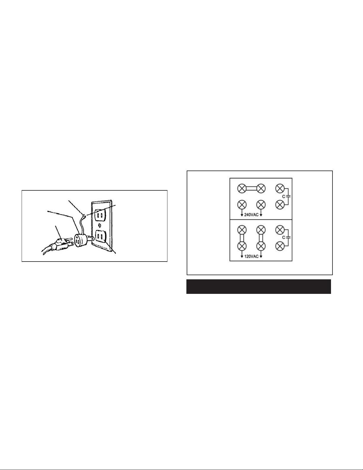
ATTACH EXTENSION TABLES
Refer to Figure 13.
IMPORTANT:
Table is coated with a protectant. To ensure
proper t and operation, remove coating. Coating is easily
removed with mild solvents, such as mineral spirits, and a
soft cloth. Avoid getting solution on paint or any of the rubber
or plastic parts. Solvents may deteriorate these nishes. Use
soap and water on paint, plastic or rubber components. After
cleaning, cover all exposed surfaces with a light coating of
oil. Paste wax is recommended for table top.
WARNING:
Never use highly volatile solvents. Non amma-
ble solvents are recommended to avoid possible re hazard.
Tools Required:
included).
.
Hardware Required:
8mm Hex Wrench and Straight Edge (not
Six M10 x 25 socket head bolts, six
10mm lock washers and six 10mm at washers (Hardware
bag #1).
• Assemble extension table to the table using socket head
bolts, lock washers and at washers.
• Wipe surface clean.
• Hand tighten only. Do not tighten completely until tables
are level. Use a straightedge to level tables.
• Repeat above procedure for the other extension table.
• Use a straight edge to check level and atness between
main and extension tables between main and extension
tables along their entire length.
• After tables are adjusted level and at, secure the exten-
sion tables by tightening the bolts completely.
8
Straight Edge
Figure 13
BLADE INSTALLATION
Refer to Figures 14 and 15.
CHECK TABLE ALIGNMENT
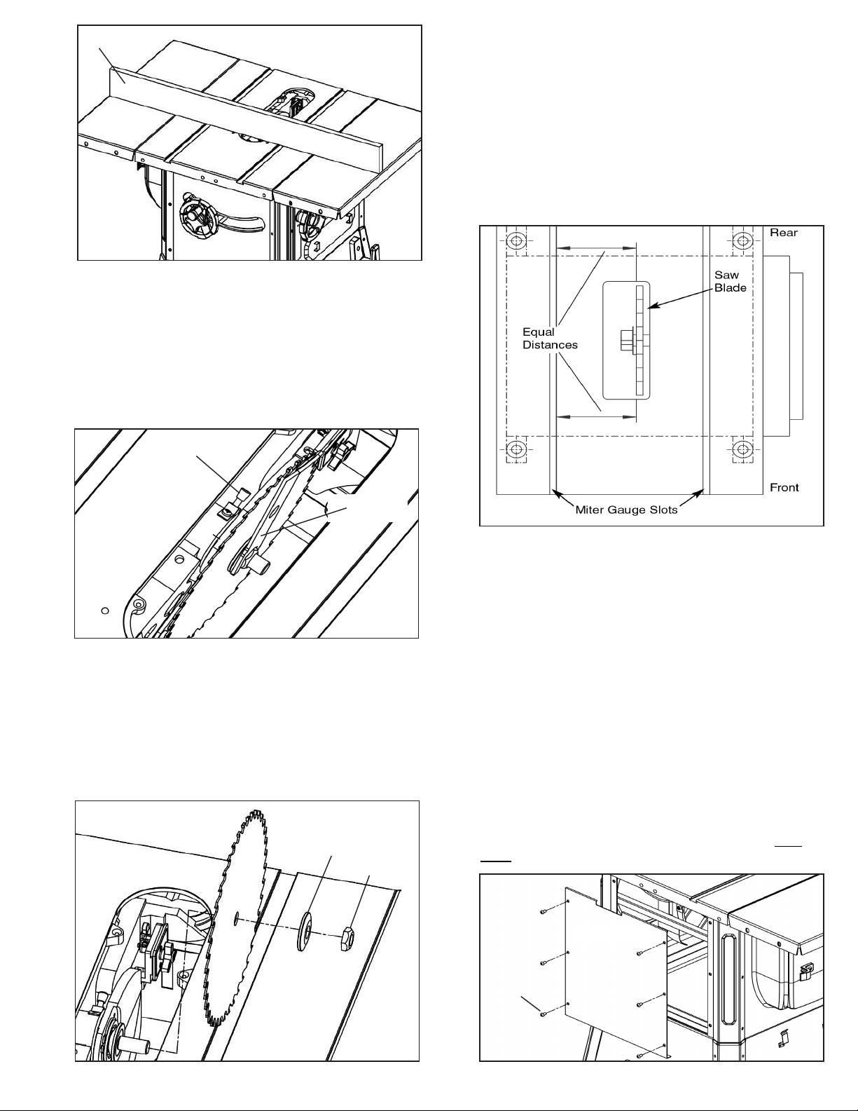
Refer to Figures 16, 17 and 18. Pages 9 and 10.
• Saws are shipped from the factory with the table adjusted
so the miter gauge slots are parallel to the saw blade.
However, in order to obtain the best results from the saw, it
is suggested this adjustment be checked before operating.
• A simple method of checking alignment is as follows: Bolt
or clamp a dowel rod or similar object to miter gauge (a
combination square can be substituted). Pick out a tooth
on front of blade and set the dowel to it so it is just touching.
Move same tooth to back of blade.
Tools Required:
24mm Open end Wrench.
• Loosen knob on right side of cabinet.
• Remove blade and wrench. Replace knob.
• Ensure the blade assembly is raised all the way up.
• Depress arbor lock and use wrench to loosen ange nut.
Remove ange and nut from arbor.
Depress Arbor Lock
24MM
Wrench
Figure 14
BLADE INSTALLATION Cont.
Refer to Figures 14 and 15.
• Place blade on arbor. Make sure arrow on blade and teeth
point towards front of saw.
• Replace ange and nut on arbor. Depress the arbor lock
and rotate arbor by hand until arbor locks in place. Keep
arbor lock depressed and use 8mm Hex Wrench to fully
tighten blade onto arbor.
Figure 15
Flange
Nut
Figure 16
• Gauge this tooth with the dowel rod. If the tooth is in the
same position, relative to the miter gauge slot, the table is
parallel with the blade. In short, the miter gauge slots must
be parallel with the blade. This means that when measuring
distance between blade and miter gauge slot at the
front and rear of the blade, the distances will be equal
(see Figure 16).
NOTE:
Be sure to measure the distance or make the test
on the same tooth of the saw blade in both front and rear
positions.
CHECK TABLE ALIGNMENT Cont.
Refer to Figures 16, 17 and 18. Pages 9 and 10.
• If an adjustment is necessary, proceed as follows: Loosen
and remove the six socket pan head screws and the rear
panel (see Figure 17). Loosen the four hex head bolts on
the trunnion (see Figure 18) and shift trunnions until a
position is found where the saw blade is parallel to the
miter guage slots.
NOTE:
Saw blade should also be centered within its table
insert opening.
Figure 17
Rear Panel
Pan Head
Screw (x6)
9
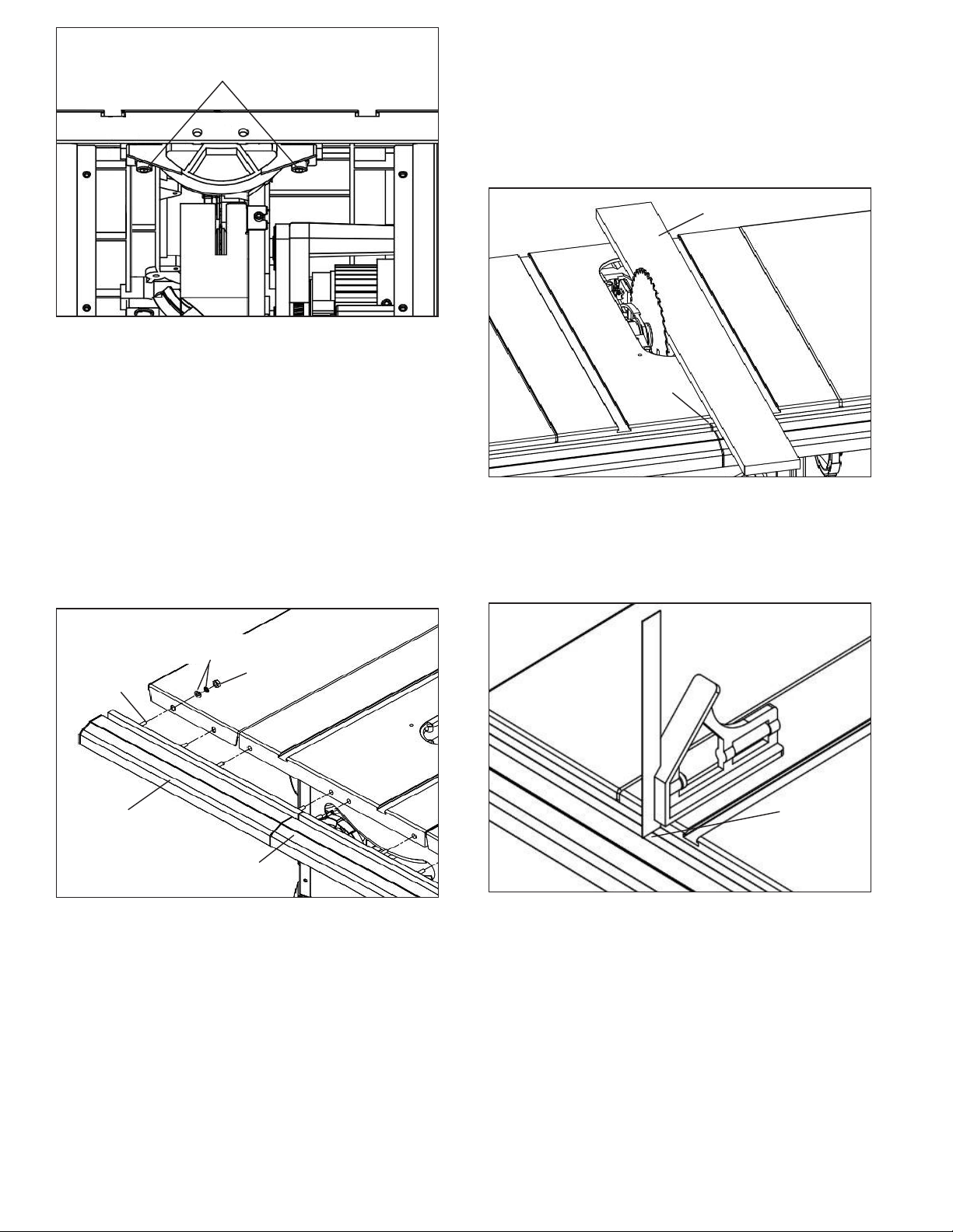
Figure 18
Trunnion Bolts (x4)
• Tighten the four trunnion hex head bolts and lock washers
securely.
This procedure will set the table and blade in parallel
position and prevent the trunnion from shifting.
NOTE:
If you perform this adjustment, leave the back panel
o to perform rear rail assembly as described in the next
section.
RAIL ASSEMBLY
Refer to Figures on Pages 10 and 11.
Tools Required:
Hardware Required:
13mm Open end Wrench
Sixteen M8 x 30 hex head bolts,
sixteen 8mm lock washers, sixteen 8mm at washers and
sixteen M8 hex nuts. (Hardware bag #2).
NOTE:
Hand tighten all hardware during rail assembly. Do
not completely tighten hardware until all rails are mounted.
NOTE:
You may have to shift right rail as far right as it will go
to attach left rail.
• Position rails so that rails are butted together and the joint
between rails is aligned with right side of the blade. You
may need a mallet to lightly tap rails together. Make sure
rails are completely butted together at the joint.
Figure 20 Straight Edge
Rail
Joint
• Use a straight edge to align right edge of rail joint to blade.
Fully tighten right rail.
• Use a level to check level and atness between right and
left rail. When level, fully tighten left rail.
• Before proceeding, ensure all hardware is tightly secured.
Figure 19
M8 Flat & Lock
M8 x 30 Hex
Head Bolts
Short Rail
(Left)
Washers
M8 Hex
Head Nut
Long Rail
(Right)
RAIL ASSEMBLY Cont.
Refer to Figures on Pages 10 and 11.
NOTE:
For this procedure the longer rail is installed to the
right; the shorter rail is installed to the left.
• Assemble the left front rail to the right front rail. Slide the
protruding pins from the left rail into the pin slots of the right
rail.
• Insert four M8 x 30 hex head bolts into the T-slot of the right
front guide rail.
• Insert four M8 x 30 hex head bolts into the T-slot of the left
front guide rail.
• Attach the assembled front rail to the table casting and to
the right and left table extensions using at washers, lock
washers and hex nuts.
Figure 21
Check Gap
Along Rail
• To allow for attachment of rear rails, loosen and remove the
six socket pan head screws and back panel. Figure 23,
page 11.
• Install and level the rear rails in the same manner as the
front rails. Use a straight edge to align the left edge of rail
joint to the blade. Figure 22, page 11.
• Before proceeding, ensure all hardware is tightly secured.
• Replace back panel of the cabinet. Figure 23, page 11.
10
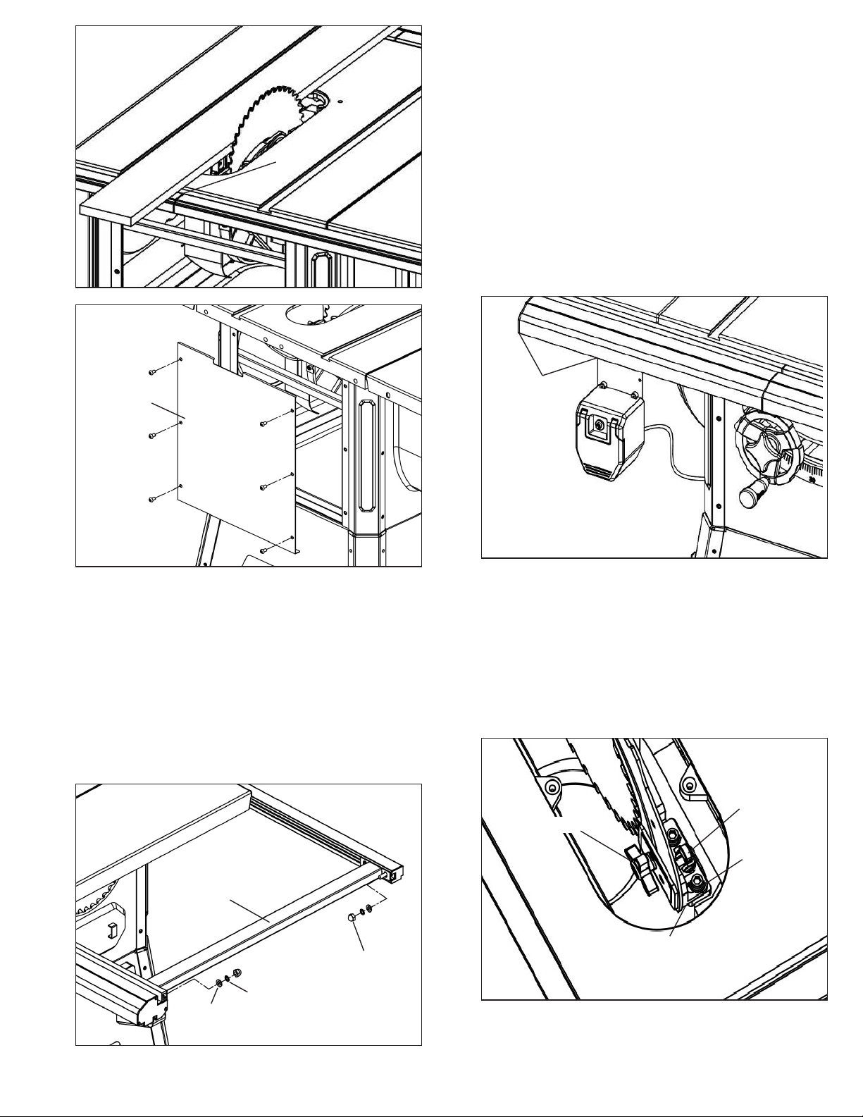
Figure 22
ATTACH SWITCH ASSEMBLY
Refer to Figure 25.
Figure 23
Replace
Rear Panel
Straight Edge
Rail
Joint
Tools Required:
Hardware Required:
at washers, two M6 lock washers and two M6 hex nuts.
(Hardware bag #3).
• From the top of the switch bracket, insert two bolts
through bracket holes.
• Loosely attach at washer, lock washer and nut to bolts.
• Insert bolt heads into T-slot on bottom of left front rail.
• Slide switch assembly 6″ to 8″ from left end of rail as
shown in Figure 25.
• Fully tighten at washers, lock washers and hex nuts to
secure switch assembly in place.
6″ to 8″ from
Left End of Rail
10mm Open end Wrench.
Two M6 x 16 hex head bolts, two M6
RAIL BRACE INSTALLATION
Refer to Figure 24.
Tools Required:
Hardware Required:
four 8mm lock washers, four 8mm at washers and four M8
acorn nuts. (Hardware bag #2).
• Insert four M8 x 16 hex bolts through holes in bracket at
each end of brace.
• Attach brace to the far right end of the rails by sliding hex
bolts into the rail T-slots. Secure bolts in position with 8mm
at washers, 8mm lock washers and 8mm acorn nuts.
Figure 24
13mm Open end Wrench
Four M8 x 16 hex head bolts,
Brace
8mm
Lock Washer
8mm
Flat Washer
8mm
Acorn Nut
Figure 25
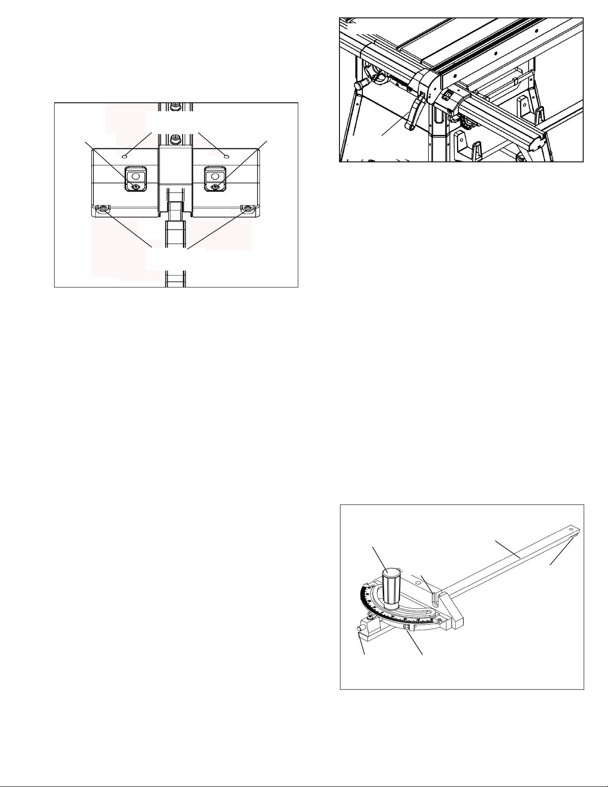
RIVING KNIFE POSITION AND ADJUSTMENT
Refer to Figure 26.
• The riving knife is pre-installed on the saw. Raise the blade
completely to access the riving knife.
• Loosen the locking knob and raise the riving knife to its
highest position. Riving knife has three holes for three posi-
tions. The highest position is for all thru cuts. The middle
position is for rabbets and other non-thru cuts, (with guard
and pawls removed). The lowest position is for dado cuts.
Figure 26
Locking Pin
Locking Knob
Socket Head
Cap Screw
Riving Knife
Bracket
RIVING KNIFE POSITION AND ADJUSTMENTS
CONTINUED ON PAGE 12
11
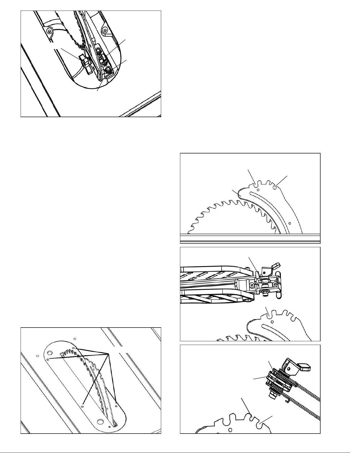
Figure 26
Locking Pin
Locking Knob
Socket Head
Cap Screw
Riving Knife
Bracket
• Make sure locking pin is aligned with riving knife hole and
secure in position by tightening locking knob.
• Riving knife must be in line with blade. Make sure riving
knife sits at against mounting bracket and lock plate.
ATTACH BLADE GUARD AND ANTI-KICKBACK
PAWLS
Refer to Figures 28-31, pages 12 and 13.
• Place the slot of blade guard body over the riving knife.
Slot of bushing is placed in the notch indicated in Figures
28 and 29.
• The bushings have a beveled edge and must be located in
the center of the notch to lock properly.
• Position guard completely down on riving knife and press
latch to lock in position.
• Blade guard body should be parallel to the table. If not,
adjust the 2mm set screws as necessary.
• Place anti-kickback pawl set onto riving knife at notches
indicated. The spring pin is placed in the front notch and
bolt is placed in the rear notch.
• Press pawl set completely down and press latch to secure
in position.
NOTE:
The teeth of anti-kickback pawls should touch table
surface. Use set screws to adjust if needed.
RIVING KNIFE TO BLADE ADJUSTMENT
Refer to Figure 26.
• Riving knife to blade clearance: the gap between the riving
knife and the saw blade should be an even distance
across the entire radius.
• The riving knife should also be in line with the saw blade. If
adjustment is necessary:
1. Locate the riving knife bracket.
2. Loosen the two socket head cap screws slightly enough
to move the bracket, bringing the riving knife in line with
the saw blade. Make sure the gap between the blade
and knife is even and from 1⁄4″ to 5⁄16″ in distance.
3. Once the riving knife is aligned with the blade, tighten
the socket head cap screws.
INSTALL TABLE INSERT
Refer to Figure 27.
• Make sure that the riving knife is raised to its highest
position.
• Place table insert into throat of table.
• Insert is held in position by magnet in table.
• To adjust insert level with table, adjust leveling screws up
or down.
Figure 28
Figure 29
Blade Guard Position
Pawl Set Position
Riving Knife
Bushing
Notch
Figure 27
Leveling Screws
Figure 30
Bolt
Pin
Insert Pin Here
Insert Bolt
Here
12
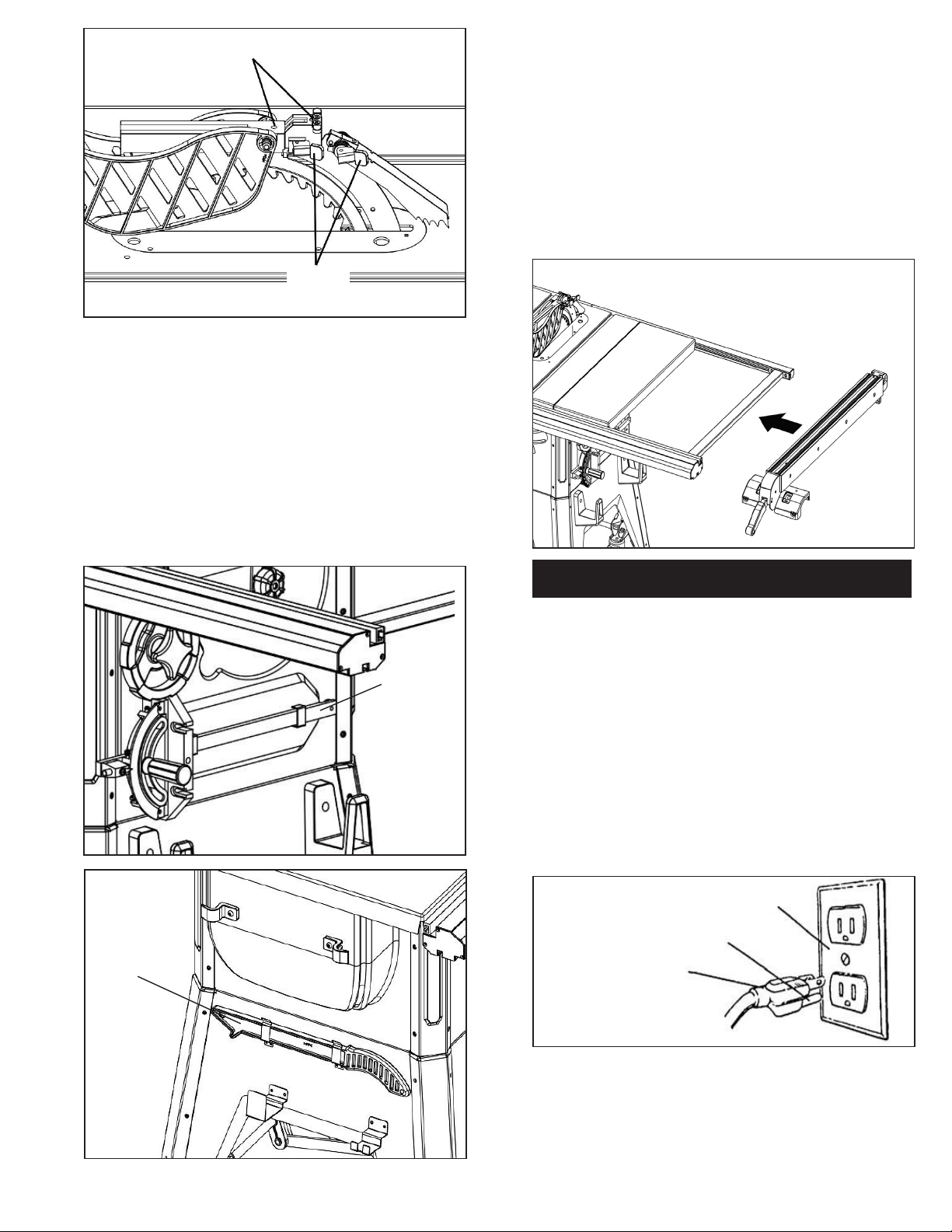
Figure 31
Set Screws
INSTALL RIP FENCE
Refer to Figure 34.
• Position rip fence assembly at end of saw. Be certain
locking lever is in UP unlocked position.
• Place rip fence assembly onto rails, positioning clamp over
rear rail and then placing rip fence onto front guide rail.
• Rip fence should now ride freely on rip fence rails. Once
rip fence is completely installed, it should be parallel with
the miter gauge and perpendicular to the table. If not, refer
to “Rip Fence Adjustment” found on pages 16 and 17 in the
Operation section of this manual.
Latches
NOTE:
The tension of the latch operation for both the Blade
Guard and Pawl Set is pre-set at the factorty. Adjustment (if
needed) can be done by loosening or tightening the 10mm
nylon locking nut on the opposite side of each latch.
INSTALL MITER GAUGE AND PUSH STICK
Refer to Figures 32 and 33.
• The miter gauge comes preassembled. Unpack the miter
gauge and clean thoroughly. Insert into storage slots on
right side of cabinet.
• Insert the push stick into brackets on left side of base.
Miter Gauge
Figure 32
Figure 34
INSTALLATION
GROUNDING INSTRUCTIONS
WARNING:
conductor can result in the risk of electrical shock. Equipment should be grounded while in use to protect operator
from electrical shock.
• Check with a qualied electrician if grounding instructions
are not understood or if in doubt as to whether the tool is
properly grounded.
• This tool is equipped with an approved 3-conductor cord
rated at 300V and a 3-prong grounding type plug
(see Figure 35) for your protection against shock hazards.
• Grounding plug should be plugged directly into a properly
installed and grounded 3- prong grounding-type receptacle,
as shown (Figure 35).
Improper connection of equipment grounding
Figure 33
Push Stick
Properly Grounded Outlet
Grounding Prong
3-Prong Plug
Figure 35
CONTINUED ON PAGE 14
13
• Do not remove or alter grounding prong in any manner. In
the event of a malfunction or breakdown, grounding
provides a path of least resistance for electrical shock.
WARNING:
plug when installing or removing from outlet.
• Plug must be plugged into matching outlet that is properly
installed and grounded in accordance with all local codes
and ordinances. Do not modify plug provided. If it will not t
in outlet, have proper outlet installed by a qualied
electrician.
• Inspect tool cords periodically and if damaged, have them
repaired by an authorized service facility.
• Green (or green and yellow) conductor in cord is the
grounding wire. If repair or replacement of the electric cord
or plug is necessary, do not connect the green (or green
and yellow) wire to a live terminal.
• Where a 2-prong wall receptacle is encountered, it must be
replaced with a properly grounded 3-prong receptacle
installed in accordance with National Electric Code and
local codes and ordinances.
WARNING:
electrician.
A temporary 3-prong to 2-prong grounding adapter (see
Figure 36) is available for connecting plugs to a two pole
outlet if it is properly grounded.
Do not permit ngers to touch the terminals of
This work should be performed by a qualied
Extension Cord Length (120V Operation)
Wire Size A.W.G.
Up to 25 ft. . . . . . . . . . . . . . . . . . . . . . . . . . . . . . . . . .14
Up to 50 ft. . . . . . . . . . . . . . . . . . . . . . . . . . . . . . . . . .12
NOTE:
recommended.
ELECTRICAL CONNECTIONS
WARNING:
power source before inspecting any wiring.
The saw is prewired for use on a 120 volt, 60Hz power
supply.
The power lines are inserted directly onto the switch. The
green ground line must remain securely fastened to the
frame to properly protect against electrical shock.
240 VOLT OPERATION
• To use the saw with a 240V, single-phase power supply,
have a qualied electrician attach a 240 volt, 15A 3-prong
(NEMA 6-15P) plug onto saw line cord and install the proper
connectors and receptacles to power supply.
• See wiring diagram (Figure 37) for wiring instructions.
Using extension cords over 50 ft. long is not
Make sure unit is o and disconnected from
Figure 37
Grounding Lug
Adapter
3-Prong Plug
• Do not use a 3-prong to 2-prong grounding adapter unless
permitted by local and national codes and ordinances.
• (A 3-prong to 2-prong grounding adapter is not permitted
in Canada.) Where permitted, the rigid green tab or terminal
on the side of the adapter must be securely connected
to a permanent electrical ground such as a properly
grounded water pipe, a properly grounded outlet box or a
properly grounded wire system.
• Many cover plate screws, water pipes and outlet boxes are
not properly grounded. To ensure proper ground, grounding
means must be tested by a qualied electrician.
EXTENSION CORDS
• The use of any extension cord will cause some drop in
voltage and loss of power.
• Wires of the extension cord must be of sucient size to
carry the current and maintain adequate voltage.
• Use the table to determine the minimum wire size (A.W.G.)
extension cord.
• Use only 3-wire extension cords having 3-prong grounding
type plugs and 3-pole receptacles which accept the tool
plug.
• If the extension cord is worn, cut, or damaged in any way,
replace it immediately.
Figure 36
Make Sure
This Is
Connected
To A Known
Ground
2-Prong Receptacle
Wiring Schematic
OPERATION
DESCRIPTION
The Craftsman 10″ Model Number 58833 contractor saw
oers precise cutting performance for all woods up to 3-1⁄8″
thick. The saw is designed for the professional user and is
ruggedly constructed for continuous service. The 10″ Saw is
recommended for use with a 10″ blade.
The saw features an extra large cast iron table. Saw body
has on board storage for push stick, miter gauge, rip fence
and saw blades. Saw is equipped with a riving knife and a
clear acrylic blade guard with anti-kickback feature. Cabinet
is constructed of heavy gauge welded steel, totally enclosed
and is ported for a 4″ vacuum hose.
Rip Fence Assembly features a heavy-duty precision rip
fence that is designed for simple and one-hand
maneuverability.
Front rail is calibrated in inches and millimeters with a
magnied window for close tolerances.
14
SPECIFICATIONS
Capacity with 10″ Blade:
Depth of cut at 90°..........................................................3-1/8″
Maximum tilt angle of arbor (left)........................................45°
Depth of cut at 45°........................................................2-3/16″
Max. cut right of blade with rip fence.............................29-1/2″
Max. cut left of blade with rip fence..............................14-1/2″
Saw Dimensions:
Table height..................................................................37-3/8″
Cabinet depth...............................................................21-3/4″
Cabinet width......................................................................19″
Table area ...........................................................27″ x 20-1/8″
Front of table to blade ..................................................11-3/8″
Rip Fence Dimensions:
Rip fence .....................................................................31-5/8″
Rip fence rails (front and rear) .................................... 56-1/2″
Blade capacity maximum ...................................................10″
Blade arbor .......................................................................5/8″
Dado blade capacity maximum .........................................3/4″
Saw Construction:
Cabinet ..................................... Totally Enclosed Steel Panel
Table ........................................................................ Cast Iron
Rip fence ................. Aluminum Tube with HDPE Guide Plate
Drive system.................................................................. V-belt
Exhaust port ....................................................................... 4″
Miter gauge ............... Cast Aluminum withT-slot Roller Guide
Blade guard ......................... Acrylic with Anti-kickback Pawls
Switch ......................... Locking Paddle Switch with Overload
Arbor RPM................................................ 3450 RPM approx.
Motor:................. 1-3/4 HP, 3450 RPM, 120V/15A, 240V/7.5A
Single-Phase, Capacitor Start/Run
Gross weight .............................................................. 308 lbs
STARTING AND STOPPING THE SAW
Refer to gure 38.
WARNING:
place. Be sure blade is not in contact with workpiece when
motor is started. Start motor and allow saw to come to full
speed.
WARNING:
nameplate and power source are the same.
• The ON/OFF switch is located under the front rail of the
table saw at the left side.
• To turn saw on, stand to either side of the blade—never
inline with it. Raise large red OFF paddle and pull up ON/
OFF switch. Always allow saw blade to come up to full
speed before cutting.
• Do not turn motor switch ON and OFF rapidly. This action
overheats the motor and may cause saw blade to loosen.
• Never leave saw unattended while the power is on.
• To turn the table saw o, press the large red OFF paddle.
Never leave saw unattended until the blade has come to a
complete stop.
The saw can be locked from unauthorized use by locking
the switch. To lock the switch:
• Turn the switch to OFF position and disconnect saw from
power source.
• Pull the key out. The switch cannot be turned on with the
key removed.
Never operate saw without blade guards in
Make sure the electrical characteristics of motor
NOTE:
Should the key be removed from the switch at the ON
position, the switch can be turned o but cannot be turned on
again.
• To replace key, slide key into the slot on switch until it
snaps.
WARNING:
below table surface. If blade is tilted, return it to vertical
position. Turn o safety disconnect or circuit breaker when
saw is not in use.
Figure 38
Large Red O Paddle
BLADE HEIGHT ADJUSTMENT
Refer to gure 39.
• Blade height is controlled by handwheel on the front of the
saw.
• To adjust height, loosen locking hand knob. Rotate knob
counterclockwise approximately three turns. Turn hand
wheel to desired blade height.
CAUTION:
the surface of the material to be cut. However, if hollow
ground blades are used, raise blade to its maximum height
to allow for greater blade clearance.
• Lock blade height into position. Lock handwheel by tighten-
ing locking knob clockwise. Tighten only until snug.
IMPORTANT:
pressure is necessary to lock handwheel securely.
Figure 39
For your own safety, lower blade or cutting tool
Switch Key
Switch
For safety, blade should be raised only 1/8″above
Do not over tighten. Only a small amount of
Lock Knob
Angle Indicator
Handwheel
BLADE HEIGHT ADJUSTMENT
CONTINUED ON PAGE 16
15
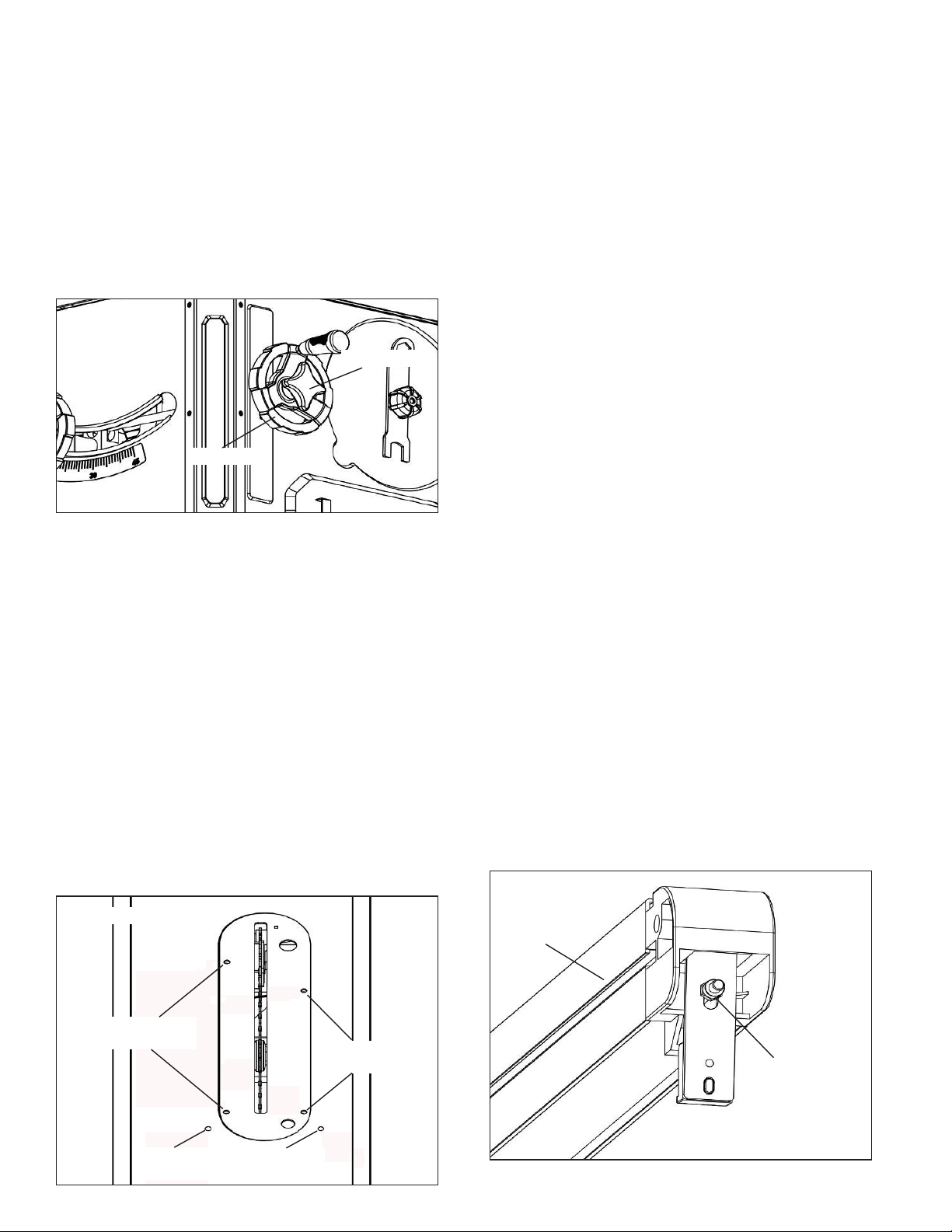
BLADE TILT ADJUSTMENT
Refer to Figures 39 and 40.
• The saw blade can be set at any angle between 90° and
45°. Blade tilt is controlled by the handwheel (Fig. 40) on
the right side of the saw. The indicator (Fig. 39, pg. 15) on
front of saw shows the tilt angle of the blade.
• To adjust tilt, loosen locking hand knob. Rotate knob coun-
terclockwise at least three turns. Turn handwheel to desired
blade angle. Lock blade angle into position.
• Lock handwheel by tightening locking hand knob clockwise.
Tighten only until snug.
• The saw is equipped with positive stops at 90° and 45°.
These positive stops allow operator to position saw blade
at 90° and 45° quickly and accurately.
Figure 40
Lock Knob
Handwheel
90° STOP ADJUSTMENT
Refer to Figures 39 thru 41.
• Raise saw blade above table as far as possible. Set blade
at 90° to table by turning the tilting handwheel. Place a
square on table and check to see if blade is perpendicular
to the table. When checking put square ush against saw
blade. Do not put square on teeth of saw blade.
• If the blade will not tilt to 90°, turn (counterclockwise) the
set screw at the left front of the table insert until the blade
can be positioned to 90°.
• Once the blade has been tilted to 90° (conrm this using
your square), tighten the bevel handwheel lock knob,
located on the side of the cabinet. This will keep the blade
from tilting further.
• Turn the set screw (clockwise) until it comes in contact
with the positive stop.
• Check tilt indicator pointer. If necessary, adjust pointer so it
points to 0° mark on scale. To adjust pointer, remove
handwheel and loosen screw on pointer. Be sure to tighten
screw securely after adjustment is completed.
Figure 41
45° STOP ADJUSTMENT
Refer to Figures 39 thru 41.
• Tilt the saw blade to 45°. Using a combination square,
check to see if blade is 45° to the table.
• If the blade will not tilt to 45°, turn (counterclockwise) the
set screw located at the right of the table insert, until the
blade can be positioned to 45°.
• With the blade at 45°, tighten the bevel handwheel lock
knob to keep the blade from further tilting.
• Turn the set screw clockwise until it comes in contact with
the positive stop.
TABLE INSERT ADJUSTMENT
Refer to Figure 41.
• The table insert must always be level with the saw table.
• Place a straight edge across the front and rear of the table
insert. Check that the insert is perfectly level with the saw
table.
• To level the table insert, turn one or more adjusting set
screws as needed and recheck.
• The table insert is equipped with two nger holes for easy
removal.
RIP FENCE ADJUSTMENT
The saw’s rip fence is precision manufactured, incorporating
ne adjustments for accurate cuts. The saw is built to allow
the operator to accurately adjust the rip fence without problems in a matter of seconds.
LEVELING THE FENCE TO THE TABLE
• Lift the lock handle to unlock the fence.
• Observe the space between the fence bottom and the
table. The space should be equal along the entire length
of the fence.
• If the space is not equal, the rails need to be adjusted so
that rails are at the same vertical position with respect to
the table. See Rail Assembly, pages 10-11.
SETTING FENCE CLAMPING PRESSURE
Refer to Figure 42.
The rip fence has been adjusted at the factory to lock
securely when the lock handle is pushed down. To adjust:
• Unlock fence and remove it from the rails.
• Adjust the hex nut until the fence is held securely when
the lock handle is pushed down.
Figure 42
Fence Body
Table Insert
Leveling Screws
90° Stop
Adjustment
45° Stop
Adjustment
Table Insert
Leveling Screws
Hex Nut
16
SETTING FENCE PERPENDICULAR AND PARALLEL
Refer to Figure 43.
PERPENDICULAR ADJUSTMENT
• Position fence anywhere on table and lock it down.
• Place a square on the table next to the fence and check to
see that the fence is at 90° to the table.
Figure 44
Figure 43
Curser Screw
PARALLEL ADJUSTMENT
• Position fence so that fence edge is aligned with slot edge.
• Slot and fence edge should be parallel.
• If an adjustment is necessary, unlock the fence and turn
either of the two adjusting screws.
• Lock fence in position and recheck. Continue this proce-
dure until fence is square to the table.
CURSOR ADJUSTMENT
Refer to Figure 43.
• Raise the saw blade above the table.
• Position the fence several inches to the right of the saw
blade.
• Lock the fence down and measure the exact distance
between the saw blade and the inside of the fence.
• Loosen the screw on the right lens and slide it left or right
until the cursor (red line) equals the measurement obtained
in the previous step.
• Retighten the screws and make a test cut. Measure the
cut piece to verify that the cursor is correctly set.
• Ax the rip fence several inches to the left of the saw blade
and perform the procedure described above for the left
lens.
NOTE:
This adjustment should be checked whenever a new
blade is installed.
Perpendicular
Adjustment
Curser Screw
Parallel
Adjustment
Fence Locking
Lever
MITER GAUGE ADJUSTMENT
Refer to Figure 45.
• Miter gauge supplied with saw is equipped with individually
adjustable index stops at 0° and 45°, right and left, and
can be manually adjusted up to 60° right and left.
Adjustment to index stops can be made by loosening the
desired locking nut and tightening or loosening three adjust ing screws. Be sure to tighten locking nut after adjustment
is made.
• Face of the miter gauge has two holes for the purpose of
attaching an auxiliary fence.
• Miter gauge is accurately constructed for precision work
and is guided through the T-slot with a roller guide
mounted at front of guide bar. Roller guide adds to miter
gauge’s stability and prevents the guide bar from leaving
the T-slot.
• To operate the miter gauge, simply loosen locking handle
and move the miter gauge body to the desired angle. The
miter gauge will stop at 0° and 45°, both right and left. To
position miter gauge body past these points, simply pull out
gauge stop.
• Position the miter gauge body at desired angle and tighten
the locking handle.
• Ensure the workpiece is straight and tight against miter
gauge body so that the workpiece does not rock or rotate.
Always use both hands when operating the miter gauge.
• The miter gauge is used for cross-cutting, compound miter
cutting, miter cutting, rabbeting, bevel cutting and dadoing.
Figure 45
Locking Handle
Miter Gauge
Body
Guide Bar
Roller Guide
RIP FENCE OPERATION
Refer to Figure 44.
• Unlock the fence by lifting the locking lever. Using the
scale for placement, position the rip fence. Lock the rip
fence into position by placing the locking lever in the down
position.
• The rip fence is used for the following operations: ripping,
bevel ripping, ploughing, resawing, rabbeting and dadoing.
17
Gauge Stop
Index Stop Adjusting
Screw & Lock Nut (x3)
INSTALLING AND REMOVING THE RIVING KNIFE
Refer to Figure 46. Additional instructions on page 12.
Install:
• Line up the riving knife in the proper direction to the
mounting bracket.
• Push the riving knife all the way down into the mounting
bracket. Make sure the lock pin is locked in the hole of the
riving knife. (The lock hole is on the button side of the
riving knife).
• If the riving knife is not locked properly, hold the locking
knob and pull the lock pin out; then re-insert the pin
securely in the hole of the riving knife. While raising or
lowering the knife, pin will snap in the hole of the knife when
located at one of the three positions.
• Tighten the locking knob.
Figure 47
Arbor Lock
Pin
Blade Wrench
Figure 46
Lock Pin
Riving Knife
Locking
Knob
Remove:
• Loosen the locking knob.
• Hold the knob and pull the locking pin out.
• Remove the riving knife out of the mounting bracket.
NOTE:
Make sure blade is at the highest position before
adding or removing the riving knife.
CHANGING THE SAW BLADE
Refer to Figure 47.
WARNING:
power cord from its power source when changing the saw
blade.
WARNING:
stamped onto the riving knife. You must select a blade with a
kerf width larger than the thickness of the riving knife.
Thinner blades may cause the workpiece to bind during cutting.
WARNING:
holes, rated at or higher than 3800 R.P.M.
• Remove blade guard assembly and pawl assembly.
• Remove the table insert.
• Unlock the raise/lower handwheel lock and raise saw
blade to maximum height.
• Depress the arbor lock pin (see Figure 47) and slowly
rotate blade toward you until pin engages into arbor. Hold
arbor in locked position.
Turn the power switch “OFF” and unplug the
When replacing blades, check the thickness
USE ONLY 10″ diameter blades with 5⁄8″ arbor
• Place supplied open-end wrench on the arbor nut. Turn
wrench counterclockwise to loosen nut. Remove arbor nut,
blade ange and saw blade.
• Place new blade on arbor. Make sure saw blade teeth
point down at the front side of saw table. Place ange and
nut on arbor and securely snug blade in position.
• Replace table insert.
• Replace blade guard assembly and pawl assembly.
TYPES OF SAWING OPERATIONS
WARNING:
following safety precautions.
• Never make any cut freehand (without using miter gauge
or rip fence). Blade can bind in the cut and cause a kick
back.
• Always lock miter gauge or rip fence securely when in use.
• Remove rip fence from the table when miter gauge is in
use.
• Remove miter gauge from table when rip fence is in use.
• Make sure blade guard is installed for all “through sawing”
operations. Through sawing operations are those opera-
tions in which the saw blade cuts completely through the
thickness of the wood. Replace guard immediately after
completion of resawing, rabbeting and dadoing.
Frequently check action of anti-kickback pawls by passing
the workpiece alongside the spreader while saw is o. Pull
the workpiece toward you. If the pawls do not dig into the
workpiece and hold it, the pawls must be sharpened. (See
Maintenance section, page 20.)
• Have blade extend approximately 1/8″ above top of work
piece. Additional blade exposure increases hazard
potential.
• Do not stand directly in front of blade in case of a kickback.
Stand to either side of the blade.
• Keep your hands clear of the blade and out of the path of
the blade.
• If the blade stalls or stops while cutting, turn switch OFF
and safety disconnect OFF before attempting to free the
blade.
• Do not reach over or behind the blade to pull the workpiece
through the cut, to support long or heavy workpieces,
to remove small cut-o pieces of material or for
any other reason.
For your own safety, always observe the
18
 Loading...