

Craftsman 11329450 Owner’s Manual

Sears owners manual
MODEL No.
113.29450
CAUTION:
Read Safety
Rules and
Instructions
Carefully
• Assembly
• Operating
• Repair Parts

CRArT MR"/
SAFETY RULES FOR POWER TOOLS
I. KNOW YOUR POWER TOOL
Read the owner's manual carefully. Learn its applica-
tion and limitations as well as the specific potential
hazards peculiar to this tool.
2. GROUND ALL TOOLS
If tool is equipped with three-prong plug, it should be
plugged into a three-hole receptacle. If adapter is used
to accommodate two-prong receptacle, the adapter wire
must be attached to a known ground. Never remove
third prong.
3. KEEP GUARDS IN PLACE
and in working order.
4. REMOVE ADJUSTING KEYS AND
WRENCHES
Form habit of checking to see that keys and adjusting
wrenches are removed from tool before turning on tool.
5. KEEP WORK AREA CLEAN
Cluttered areas and benches invite accidents.
6. AVOID DANGEROUS ENVIRONMENT
Don't use power tools in damp or wet locations. Keep
work area well illuminated.
7. KEEP CHILDREN AWAY
All visitors should be kept a safe distance from work
area.
8. MAKE WORKSHOP KID PROOF
--with padlocks, master switches, or by removing
starter keys.
9. DON'T FORCE TOOL
It will do the job better and be safer at the rate for
which it was designed.
I0. USE RIGHT TOOL
Don't force tool or attachment to do a job it was not
designed for.
11.
WEAR PROPER APPAREL
No loose clothing or jewelry to get caught in moving
parts.
12.
USE SAFETY GLASSES
Also use face or dust mask if cutting operation is dusty.
13.
SECURE WORK
Use clamps or a vise to hold work when practical. It's
safer than using your hand, frees both hands to oper-
ate tool.
14. DON'T OVERREACH
Keep your proper footing and balance at all times.
15.
MAINTAIN TOOLS IN TOP
CONDITION
Keep tools sharp and clean for best and safest per-
formance. Follow instructions for lubricating and
changing accessories.
16. DISCONNECT TOOLS
before servicing and when changing accessories such
as blades, bits, cutters.
17.
AVOID ACCIDENTAL STARTING
Make sure switch is "OFF" before plugging in cord.
18.
USE RECOMMENDED ACCESSORIES
Consult the owner°s manual. Use of improper acces-
soriesmay be hazardous.
WEAR YOUR
Copyright 1969 by Power Tool Institute, Inc. All rights reserved.
The operation of any power tool can result in foreign objects
being thrown into the eyes, which can result in severe eye
damage. Always wear safety glasses or eye shields before
commencing power tool operation. We recommend Wide
Vision Safety Mask for use over spectacles, or standard safety
glasses.., available at Sears retail or catalog stores.
THIS SAFETY SEAL OF THE
POWER TOOL INSTITUTE ASSURES YOU...
1. That the manufacturer's power tools, including the particular tool
associated with the Seal, are produced in accordance with applicable
Standards For Safety of Underwriters' Laboratories and American
National Standards (ANSI).
2. That compliance with applicable safety standards is assured by in-
dependent inspection and testing conducted by Underwriters" Labora-
tories (UL).
3. That every motorized tool is inspected under power.
4. That every tool has with it adequate instructions and a list of safety
rules for the protection of the user.
5. That the tool manufacturer is a member of the Power Tool Institute and
is a sponsor of the Institute's Consumer Safety Education Program.

ASSEMBLING AND ADJUSTING YOUR SAW
10 9
1
2
7
4
S
Figure 1
UNPACKING AND CHECKING CONTENTS
This Craftsman 10olnch Radial Saw is shipped complete in
one carton. In order to prevent damage during shipment
and facilitate packaging, certain items are removed at the
factory and must be assembled when received by the pur-
chaser. These "loose" items are listed below and should be
accounted for before discarding any packing materials.
Key No.
(Fig. 1) Item Name Qty.
1
2
3
4
5
6
7
8
9
10
11
Table Support, Left-hand .......... 1
Table, Front ..................... 1
Table, Rear ...................... 1
Table, Spacer .................... 1
Fence, Rip ....................... 1
Table Support, Right-hand ......... 1
Owner's Manual .................. 1
Unpacking Instructions ............. 1
Shaft Wrench .................... 1
Arbor Wrench .................... 1
Pack Assm., Loose Parts
(containing the following):
Wrench, Hex-L, 1/8" ............ 1
Wrench, Hex-L, 3/16" ........... 1
Wrench, Hex-L, 1/4" ............ 1
Wrench, Hex-L, 5/16" ........... 1
Washer, Plain, 11/32 x 7/8 x1/16 _/ 4
Lockwasher, 5/16x.125 x.078" . . . 4
Screw, Hex. Hd. 5/16-18 x 3/4 'I ... 4
Screw, M. Pan. SI., 1/4-20 x 1" .... 6
Washer, Plain, 17/64 x 5/8 x 1/32 p_ 7
Lockwasher, Steel, 1/4 x .109 x .062" 6
Nut, Hex., 1/4-20x7/16 x 3/16" .. 6
Nut, Tee ...................... 1
Key No.
(Fig. 1) Item Name Qty.
Screw, M. Pan. SI., 1/4-20x1-1/4" 1
Screw, SI. Cup Pt., Set, 1/4-20 x 1/2" 1
Screw, Type A, Pan Hd., Sl.,
No. 10x5/8" ................ 4
Screw, Type 23, Pan Hd., Sl.,
No. 6-32 x 5/16" ............. 2
Nut, U-Clip (1/4-20) ............ 1
Clamp, Table .................. 2
Switch Key .................... 2
Shoe, Carriage Lock ............ 1
Knob, Carriage Lock ............. 1
Indicator, Rip .................. 1
Nut, Twin ..................... 1
Bracket, Rear Table Support ...... 2
POWER SUPPLY AND MOTOR DATA
MOTOR SPECIFICATIONS
The a-c motor used in this Craftsman Radial Saw is of
the capacitor start, non-reversible type with the following
specifications:
Voltage .......................... 120
Amperes ........................ 12.5
Hertz ............................ 60
Phase ......................... Single
RPM ............................ 3450
Rotation (viewing saw blade end) Clockwise
CAUTION: This motor is wired for 120 volt
operation. Connect to 15 ampere branch
circuit and use a 15 ampere time-delay fuse.
3

MOTOR SAFETY PROTECTION
The saw motor is equipped with a manual-reset thermal
overload protector, designed to open the power line circuit
when the motor temperature exceeds a safe value.
1. If the protector opens the line and stops the saw motor,
press the saw switch to the "OFF" position immediately
and allow the motor to cool.
2. After cooling to a safe operating temperature, the
overload protector can be closed manually by pushing
in the red button on the motor cover and nameplate. If
the red button will not snap into place immediately, the
motor is still too hot and must be allowed to cool for a
while longer. (An audible click will indicate protector
is closed.)
3. As soon as the red button will snap into running position,
the saw may be started and operated normally by
pressing the saw switch to the "ON" position.
4. Frequent opening of fuses or circuit breakers may result
if motor is overloaded, or if the motor circuit is fused
with a fuse other than those recommended. Do not use
a fuse of greater capacity without consulting the power
company.
5. Although the motor is designed for operation on the
voltage and frequency specified on motor nameplate,
normal loads will be handled safely on voltages not more
than 10% above or below the nameplate voltage. Heavy
loads, however, require that voltage at motor terminals
be not less than the voltage specified on nameplate.
6. Most motor troubles may be traced to loose or incorrect
connections, overloading, reduced input voltage (which
results when small size wires are used in the supply
circuit) or when the supply circuit is extremely long.
Always check connections, load and supply circuit when
the motor fails to perform satisfactorily. Check wire
sizes and lengths with the table in the next paragraph.
IMPORTANT: The following wire sizes are
recommended for connecting the motor to
power source for trouble-free operation.
Length of Wire Size Required
Conductor (American Wlre Gauge No.)
50 feet or less ................. No. 12
100 feet or less ................. No. 10
100 feet to 150 feet ............. No. 8
150 feet to 200 feet ............. No. 6
200 feet to 400 feet ............. No. 4
For circuits of greater length the wire size must be in-
creased proportionally.
MOUNTING THE SAW ON A WORK BENCH
The saw should be placed on a suitable sturdy work bench,
or Craftsman Power Tool Bench. The base of the saw must
be mounted flush to a flat surface on the work bench to
prevent distortion of the saw base. The nuts, screws, and
washers which attach the wooden shipping skids to the
saw base may be used to secure the saw base to the work
bench, or tool bench.
ALIGNMENT INSTRUCTIONS
NOTE: The seven basic "steps" that follow are
essential in order to insure correct saw table
alignment.
WARNING: Make sure the power cord is
not plugged into an electrical outlet when
working on the saw.
STEP ONE--INSTALLATION AND ADJUSTMENT
OF TABLE SUPPORTS
1. Place the saw on a work bench or table.
2. Attach right-, and left-hand table supports to the saw
base as follows: (See figure "2.)
NOTE: Right-, and left-hand supports may be
identified by the three "keyholes" in the table
attaching surface of each support. These key-
holes are for attaching the table clamps and
are located at the rear of the saw. Also, the
angle of each support turns outward, away
from the saw base. (See figure 2.)
a. Place one 5/16-inch, split Iockwasher and one 11/32-
inch plain washer on each of the four 5/16-18 x 3/4-
inch, hex-head screws, all from the loose parts pack.
b. Attach each table support to the saw base with two
of the hex-head screws, Iockwashers and plain wash-
ers assembled in preceding step.
c. Position each support on the base so each screw is
approximately centered in the slotted hole in the
support.
d. Tighten the screws just enough to hold the table
supports in position, but loose enough to slip against
the base channel when tapped with a plastic mallet.
3. Adjust Table supports parallel to radial arm as follows:
a. Loosen the guard clamp screw and remove the guard.
b. Lock carriage and hold the motor shaft (at inner edge
of saw blade) with the shaft wrench and loosen the
I TABLE SUPPORT
(RIGHT-HAND)
PLAIN WASHER\ J
(11/32 INCH) _L'_ _--TABLE SUPPORT
_._ "'_ (LEFT-HAND)
_ LOCKWASHER (5/16 INCH)
(HEX-HD, 5/16-1_ _ 3/4 INCH)
SCREW Figure 2
ARBOR
WRENCH
SHAFT
Figure 3

SHAFT WRENCH
SAW BLADE
ARBOR
// AR OR
zJ NUT
COLLAR COLLAR LOCK
\ BEVEL KNOB
(OUTER) (INNER) KNOB
SWIVEL
INDEX
Figure 4
ELEVATION CRANK
ARM
HANDLE
TABLE
(LEFT-HAND)
ARM LOCK
HANDLE
TABLE SUPPORT
(RIGHT-HAND)
Figure 5
arbor nut and saw-blade collar with the arbor wrench.
(See figures 3 and 4). Remove nut, outer collar, saw
blade and inner collar. (See figure 4.)
c. Using the elevation crank (figure 5), raise the motor
high enough to swivel 90 ° , as described in the next
step.
d. Loosen the bevel lock knob and pull out on swivel
index knob. (See figure 4.) Swivel the motor to posi-
tion the saw end of shaft pointing straight down.
Tighten the bevel lock knob.
e. Loosen the arm lock handle (at upper right-hand side
of column) and release the arm latch handle (fig-
ure 5).
f. Move the radial arm to the left until the end of motor
shaft is directly over the left-hand table support.
g. Loosen the carriage lock knob and move the carriage
rearward as far as it will go. Then, with the elevation
crank, lower the carriage until the end of motor shaft
just touches the top surface of the left-hand table
support.
NOTE: Do not change this elevation setting
until both left- and right-hand table supports
have been adjusted.
h. Move the carriage out to the end of radial arm and
move the arm until the end of motor shaft is over the
table support at this poistion. (See figure 6.) Tap
the table support upward or downward until the end
of motor shaft just touches the surface. (See figure 6.)
i. After setting the forward position of table support,
move the carriage rearward and recheck the rear-
ward position to determine if adjusting the forward
position affected the rearward setting. Tap the table
support upward or downward as required.
j. Recheck forward and rearward positions as many
times as necessary to provide an accurate adjust-
ment of the support.
k. Tighten the two hex-head screws (figure 2) securely
to retain the adjustment. Recheck to make sure that
tightening screws did not affect the accuracy of the
adjustment.
I. Move the radial arm over to the right-hand table
support and adjust it in the same manner.
STEP TWO--ELIMINATING RADIAL ARM SIDE PLAY
1. Move the radial arm to a central (cross-cut) position and
engage the arm latch hc_ndle in the detent notch. (See
figure 7.) Tighten the arm lock handle.
NOTE: In order to insure an accurate setting
of the radial arm, refer to paragraph entitled
"Angular Movement and Locking the Radial
Arm", under "OPERATING CONTROLS".
2. Apply side force with one hand on radial arm in both
directions. If side play exists, an adjustment is required.
ii
ARM LATCH "_"% / _'_
HANDLE
< _ ° rOUCH
TA _LE SUPPORT
([ :::T-HAND)
CRANK RADIAL ARM
/
ARM LATCH
HANDLE
COLUMN ADJUSTING
SCREW
(TYPICAL)
\
ARM LOCK
HANDLE
\
(RIGHT-HAND)
P
KEYLOCKING
BOLTS
i
Figure 6
Figure 7

BOTTOM SIDE OF TABLE
FRONT
TABLE
REAR TABLE
SUPPORT BRACKET
T-NUT CORRECTLY INSTALLED
LEVELING SCRTW
BASE
TOP OF TABLE
LEVELING SCREW INSTALLED
T-NUT
IN T-NUT
Q,I
SCREW
(No. 10 x 5/8 IN.)
Figure 8
3. Loosen keylocking bolts (See figure 7) and inserta 3/16-
inch Hex-L wrench into the socket-head set-screw that
adjusts the column tube wedge key, as shown in figure 7.
Rotate the set-screw slowly in (clockwise) until no side
play can be felt in radial arm.
4. Check for binding by rotating the elevation crank. If the
crank rotates with noitceable resistance, loosen the set-
screw by rotating the Hex-L wrench counterclockwise
until rotation is normal. An effective method for finaliz-
ing the set-screw adjustment is to rotate the screw while
the elevation crank is being rotated, checking for side
play in radial arm as the adjustment progresses. The
adjustment is correct when all side play of radial arm
is eliminated and only very slight additional resistance
can be felt when rotating the elevation crank.
5. If some radial arm side play can still be detected after
performing the above adjustment, it will be necessary
to adjust the forward five screws through the right-,
and left-hand column supports as follows:
a. While rotating the elevation crank, tighten the five
column adjusting screws slightly at the forward edge
of column supports. Each screw should be tightened
only slightly, and each one the same amount, until
a slight resistance can be felt when rotating the
elevation crank, then each screw backed off just
enough to restore a normal feel to the elevation
crank.
b. Recheck the adjustment of the column tube wedge
key set-screw as outlined in preceding instructions.
COLUMN
SUPPORT
LEVELING SCREW
FRONT TABLE
HOLE FOR TABLE
HOLD-DOWN SCREW
HOLE
(SEVEN,TOTAL)
R.H. TABLE SUPPORT
Figure 9
6. After the above adjustments have been completed, re-
check the radial arm for absence of side play.
7. When all side play has been eliminated, lock the column
tube key in place by tightening keylocking bolts. (See
figure 7.)
STEP THREE--INSTALLATION OF FRONT TABLE
1. Place the large (front) table board upside-down on floor.
Distinguish between the one through-bored (leveling
screw) hole near the center of the board, and the seven
counterbore holes. The counterbores are in the top sur-
face of the board. Drive the T-nut into the through-hole.
(See figure 8 which shows the T-nut installed.)
2. With the front table board still in the upside-down posi-
tion, locate the two pre-drilled screw holes near each
end of the table. Attach the two rear table support
brackets to the table with two No. 10 x 5/8-inch screws
in each bracket. (See figure 8.)
3. Place the 1/4-20 U-clip nut on the base cross member
to receive the center front table attaching screw.
4. Place the large, front table board on the table supports.
(See figure 9.)
5. Align the counterbore holes with matching holes in table
supports.
6. Place a 17/64-inch plain washer and a 1/4-20 x 1-inch
pan-head machine screw from loose parts pack in each
of the six counterbore holes located above the table
supports. Use a 1/4-20 x 1-1/4-inch pan-head machine
screw in counterbored hole at the center of the table
board.
ii
Figure 10
Figure 11

7. Start the leveling screw into the T-nut on front table, but
do not allow the tip of the screw to protrude beyond the
bottom surface of front table.
8. Install Iockwashers and nuts on the six screws in the
table supports and tighten them finger tight. Start the
pan-head screw in the counterbored hole near the
center of front board into the U-nut on saw base, but
leave it approximately two turns loose.
9. At this time the front table should be checked and ad-
justed at the center position as follows:
a. Move carriage to maximum rear position.
b. Using one edge of the rear table board as a straight-
edge, lay the board on the front table as shown
in figure 10.
c. Sight between edge of rear table and surface of front
table, to determine if the front table is low or high
at the center position. If front table is high, tighten
the center hold-down screw until it is level, then rotate
the leveling screw clockwise until it is "snug" against
the base front member. If the table is low at the
center, loosen the hold-down screw and rotate the
leveling screw clockwise until the front table is level,
then tighten the hold-down screw.
NOTE: After tightening screws, as described
above, always recheck to make sure that the
front table remains level. In some cases, a final
"touch-up" adjustment may be required.
STEP FOUR--SQUARING THE CROSS-CUT TRAVEL
1. Loosen the bevel lock knob, pull out on swivel index
knob and swivel the motor until the swivel index knob
indexes the motor with the shaft in a horizontal (zero)
position. Tighten the bevel lock knob.
2. Check to make sure the arm latch handle is securely
latched in the detent an_l the arm lock handle is still tight.
3. Install the saw blade as follows:
a. Place the inner collar on motor shaft. (See figure 4.)
b. Slide saw blade on motor shaft. Make sure teeth are
pointed in direction of saw rotation. (See figure 42
c. Install outer collar and arbor nut.
NOTE: The arbor shaft has left-hand threads.
d. Use the shaft wrench on motor shaft and arbor wrench
on arbor nut to tighten the nut, as shown in figure 11.
e. Lower the saw blade (with elevation crank) until the
blade is approximately 1/32 inch above table surface.
4. Place a square on the table as shown in figure 12 and
position the saw and square until the leg of the square
just contacts a tooth of the saw blade. (Position "A °',
figure 12.) Mark this tooth with crayon or chalk.
5. When the blade is moved back and forth on the radial
arm, the saw tooth "A '° should just touch the square at
all positions. If saw tooth "A" does not touch the square
at oil points, make the following adjustments:
a. If saw tooth ("A", figure 12) moves away from the
square when moving the blade from the rear toward
the front of the table, tap the rear edge of front
board with a mallet on left side forward until the
table is square with the saw blade.
b. Reverse this procedure if tooth "A" moves into the
square when moving the saw from the rear toward
the front of the table.
c. Recheck blade squareness and, if correct, tighten the
six table hold-dawn screws securely.
6. After the crass-cut travel has been accurately squared,
check the 0° position on the indicator scale of the radial
arm cap to determine if the 0 ° position on the scale is
Figure 12 _ _ -
J_]_.-,,_- ELEV AT IO N CRANK
ARM LO _ -- _ j RADIAL ARM CAP
CK i "_
HANDLE _ _
l _ HANDLE
Figure 13 _ ! _
ELEVATION INDEX MARK
,L
Fjgure 14 ARM CAP AIi"ACHING SCREWS
ACCESS HOLES FOR RADIAL
aligned with index mark on radial arm. (See figure 14.)
If not aligned, proceed as follows:
a. Rotate the elevation crank to a position that will
locate the two access holes over screw heads of radial
arm cap attaching screws. (See figure 14.)
b. Loosen the two screws with a screwdriver inserted
through the access holes in elevation crank.
c. Reposition the radial arm cap by hand until the 0°
mark is aligned with the index mark and tighten the
two attaching screws.
7. In extreme cases, due to rough handling during ship-
ment, performing the above adjustment procedure may
not be sufficient. Make the following adjustment only
after tightening the table hold-down screws and the
cross-cut travel cannot be squared by performing the
preceding adjustment routine:
a. Using a 1/8-inch Hex-L wrench, loosen the two set-
screws that lock the arm latch screws. (See figure 13.)
b. Move saw blade forward along steel square (figure
12) to determine in which direction the radial arm
must be adjusted.
RADIAL ARM
i
7
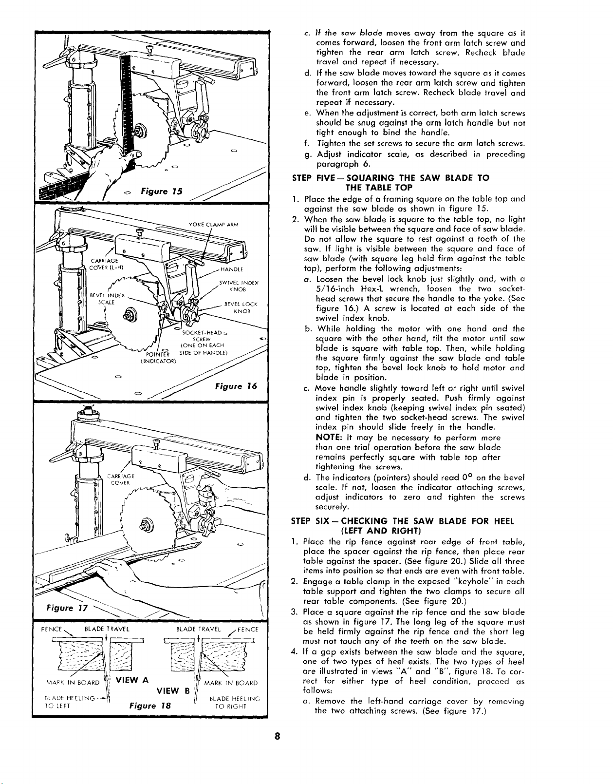
Figure 15
Figure 16
Figure 17
• I
FENCE,,,,,.,, BLADE TRAVEL BLADE TRAVEL //FENCE
BLADE.E EL,.O --ti VIEW Bill MARr._LADE,NHEEL,NGBOARD
To C[FT Figure 18 TO RIOHT
II
c. If the saw blade moves away from the square as it
comes forward, loosen the front arm latch screw and
tighten the rear arm latch screw. Recheck blade
travel and repeat if necessary.
d. If the saw blade moves toward the square as it comes
forward, loosen the rear arm latch screw and tighten
the front arm latch screw. Recheck blade travel and
repeat if necessary.
e. When the adjustment is correct, both arm latch screws
should be snug against the arm latch handle but not
tight enough to bind the handle.
f.
Tighten the set-screws to secure the arm latch screws.
g.
Adjust indicator scale, as described in preceding
paragraph 6.
STEP
FIVE--SQUARING THE SAW BLADE TO
THE TABLE TOP
1.
Place the edge of a framing square on the table top and
against the saw blade as shown in figure 15.
2.
When the saw blade is square to the table top, no light
will be visible between the square and face of saw blade.
Do not allow the square to rest against a tooth of the
saw. If light is visible between the square and face of
saw blade (with square leg held firm against the table
top), perform the following adjustments:
a. Loosen the bevel lock knob just slightly and, with a
5/16-inch Hex-L wrench, loosen the two socket-
head screws that secure the handle to the yoke. (See
figure 16.) A screw is located at each side of the
swivel index knob.
b. While holding the motor with one hand and the
square with the other hand, tilt the motor until saw
blade is square with table top. Then, while holding
the square firmly against the saw blade and table
top, tighten the bevel lock knob to hold motor and
blade in position.
c. Move handle slightly toward left or right until swivel
index pin is properly seated. Push firmly against
swivel index knob (keeping swivel index pin seated)
and tighten the two socket-head screws. The swivel
index pin should slide freely in the handle.
NOTE: It may be necessary to perform more
than one trial operation before the saw blade
remains perfectly square with table top after
tightening the screws.
d. The indicators (pointers) should read 0° on the bevel
scale. If not, loosen the indicator attaching screws,
adjust indicators to zero and tighten the screws
securely.
STEP SIX--CHECKING THE SAW BLADE FOR HEEL
(LEFT AND RIGHT)
1. Place the rip fence against rear edge of front table,
place the spacer against the rip fence, then place rear
table against the spacer. (See figure 20.) Slide all three
items into position so that ends are even with front table.
2. Engage a table clamp in the exposed "'keyhole" in each
table support and tighten the two clamps to secure all
rear table components. (See figure 20.)
3. Place a square against the rip fence and the saw blade
as shown in figure 17. The long leg of the square must
be held firmly against the rip fence and the short leg
must not touch any of the teeth on the saw blade.
4. If a gap exists between the saw blade and the square,
one of two types of heel exists. The two types of heel
are illustrated in views "A" and "B", figure 18. To cor-
rect for either type of heel condition, proceed as
follows:
a. Remove the left-hand carriage cover by removing
the two attaching screws. (See figure 17.)
8

b. Loosen the yoke clamp arm. (See figure 16.1
c. Loosen (slightly) the two hex-head screws at location
shown in figure 19.
d. With the square in position shown in figure 17, shift
the yoke until the gap between the saw blade and
square is eliminated.
e. Tighten the yoke clamp arm. Then tighten the two hex-
head screws. (See figure 19.)
f. Recheck for heel (figure 17) to make sure that tight-
ening the hex-head screws did not affect the setting.
Several trial settings may be required.
g. Re-install the left-hand carriage cover.
NOTE: If the carriage bearings need adjust-
ing for proper tension on radial arm tracks,
refer to "Carriage Bearings °' under "Adjust°
ments to Compensate for Wear". If this adjust-
ment is required, be sure to recheck for "heel"
after completing the adjustment.
STEP SEVEN- DOUBLE CHECK ADJUSTMENTS AND
1. Recheck for correct adjustment on the saw by perform-
ing "STEPS ONE through SIX" consecutively.
2. If the cross-cut travel is not perfectly squared, proceed
with "STEP FOUR" and make all adjustments listed in
the "STEP FOUR" procedure.
ADJUSTMENT OF RIP SCALE INDICATORS.
NOTE: The rip scales and pointer are intended
to be used for quick settings. For greater ac-
curacy, take direct measurement between blade
and fence.
1. When the fence is in its normal position (next to the front
table), loosen the yoke clamp arm and index the yoke
90 ° from the cross-cut position so the blade is between
the mator and the fence. Lock the yoke by tightening
the yoke clamp arm.
2. Loosen the carriage lock knob and move the motor and
carriage assembly along the radial arm until the blade,
when spun by hand, just touches the front face of the
fence. Tighten the carriage lock knob. (See figure 21.)
3. The rip-scale indicator (on the right-hand side of radial
arm) should now be aligned with the "0 °'' mark on the
lower ("In-Rip") scale. If not, loosen the two indicator
attaching screws and shift the indicator until it is aligned
with the "0 °'° mark, then tighten the attaching screws.
(See figure 21 .) When the indicator is set for the "In-Rip °'
(lower) scale, it will be correct for the "Out-Rip" (upper/
scale.
4. Loosen the carriage lock knob, move the motor and
carriage assembly outward on the arm, enough for the
blade to clear the fence. Loosen the yoke clamp arm
and index the yoke in the cross-cut position. Tighten the
yoke clamp arm.
5. Install the guard assembly, making sure the locating
notch on the guard engages with the mating "tongue"
on the motor housing. Tighten the guard clamp screw
finger tight. (See figure 22.)
ADJUSTING SPREADER ON ANTI-KICKBACK
ASSEMBLY.
1. Loosen the wing nut (figure 22) and raise the anti-kick-
back assembly to near maximum height. Tighten the
wing nut.
2. Sight (visually) to check for proper alignment of spreader
with saw blade, as shown in figure 22. If the spreader is
not aligned, adjust it as follows:
a. Loosen the two hex-head screws that secure the anti-
kickback mounting bracket, shift the spreader into
alignment with the blade and tighten the two hex-
head screws.
INSTALL GUARD
i i
HEX_HEAD__
Figure /
E
_k:d " I
. TABLESPACER Figure 20
CARRIAGE LOCK KNOB RIP SCALE INDICATOR
• Z
÷"' It" '''_ ' '''_''_' ' "_' ' "I_"' -i"_ g__ _._
YOKE __ :_ ATTACHING
CLAMPARMI- _-, SCREWS
Figure 21 __//________
Figure 22 _=_ _ _
b. Recheck to make sure that tightening the screws did
not affect the setting. Several trial adjustments may
be required.
3. Reposition spreader to maximum down position and
(sight) check alignment. Adjust position (with two hex-
head screws) until in alignment throughout the range.
4. Periodically check and maintain sharp tips on anti-kick-
back pawls.
NOTE: Two de|ents are "pressed" into the lower
end of the spreader to facilitate positioning
when ripping. The setting is correct (for anti-
kickback pawls and spreader) when upper ends
of detents are even with the surface of the board
being ripped.
_ / _INDICATOR
- i).-J /
9
 Loading...