

Craftsman 11324250 Owner’s Manual

Serial
Number
Model and serial
number may be found
at the rear
of the base.
You should record both
model and serial number
in a safe place for
future use.
12-iNCH MO TORIZED
CAUTION:
Read GENERAL
and ADDITIONAL
SAFETY
iNSTRUCTiONS
carefully
TABLE SAW
• assembly
e operating
• repair parts
Sold by SEARS, ROEBUCK AND CO., Chicago, IL. 60684 U.S.A.
Part No. 62732

FULL ONE YEAR WARRANTY ON CRAFTSMAN TABLE SAWS
If within one year from the date of purchase, this Craftsman Table Saw fails due to a defect in material or
workmanship, Searswill repair it, free of charge.
Warranty service is available by simply contacting the nearest Sears store or Service Center throughout the
United States.
This warranty gives you specific legal rights, arid you may also have other rights which vary from state to
state. SEARS, ROEBUCK AND CO.
BSC 41-3
SEARS TOWER
CHICAGO, IL 60684
general safety instructions for power tools
1. KNOW YOUR POWER TOOL 13. SECURE WORK
Read the owner's manual carefully, Learn its Use clamps or a vzse to hold work when practical. It's
application and limitations as well as the specific safer than using your hand. frees both hands to operate
potential hazards peculiar to this tool. tool.
2, GROUND ALL TOOLS 14. DON'T OVERREACH
This tool is equipped With an approved 3-conductor Keep proper footing and balance at all times.
cord and a 3-prong grounding type plug to fit the
proper ground ng type receptacle. The green conductor 15. MAINTAi N TOOLS WITH CARE
in the cord is the grounding wire. Never connect the Keep tools sharp and clean for best and safest
green wire to a live terminal, performance. Follow instructions for lubricating and
3. KEEP GUARDS IN PLACE changing accessories.
in working order, and in proper adjustment and 16. DISCONNECT TOOLS
alignment, before servicing; when changing accessories such as
4. REMOVE ADJUSTING KEYS blades,bits, cutters, etc.
AND WRENCHES 17. AVOID ACCIDENTAL STARTING
Form habit of checking to see that keys and adjusting
wrenches are removed from tool before turning it on. Make. sure switch is in "OFF" position before plugging
5. KEEP WORK AREA CLEAN
Cluttered areas and benches invite accidentS. Floor
must not be Slippery due to wax or sawdust. Consult the owner's manual for recommended
6. AVOID DANGEROUS ENVIRONMENT the accessories. The use of improper accessories may
Don't use power tools in damp or wet locations or
expose them to rain. Keep work area well lighted.
Provide adequate surrounding work space.
7. KEEP CHILDREN AWAY
Al! visitors should be kept a safe distance from work
area.
8. MAKE WORKSHOP KID-PROOF
-- with padlocks, master switches, or by removing
starter keys. 20. CHECK DAMAGED PARTS
9. DON'T FORCE TOOL Before further use of the tool, a guard or other part that
It will do the .,ob betterand safer at the rate for which is damaged should be carefully checked to ensure that it
it was designed, wit! operate properly and perform its intended function.
10. USE RIGHT TOOL Check for alignment of moving parts, binding of moving
Don't force tool or attachment to do a job it was not
designed for. conditions that may .affect its operation. A guard or
11. WEAR PROPER APPAREL or replaced.
Do not wear loose clothing, gloves, neckties or jewelry
(rings, wrist watches) to get caught in moving parts.
Nonslip footwear is recommended. Wear protective
hair covering to contain long hair_ Roll Iongsleeves Feed work into a blade or cutter against the eirection
above the elbow, of rotation of the blade or cutter only.
12. USE SAFETY GOGGLES (Head Protection)
Wear Safety goggles (must comply with ANS Z87.1) at
all times, Also, use face or dust mask if cutting .... UNATTENDED
operation is dusty, and ear protectors (piugs,or muffs_ Turn power off; Don't leave tool until it comes to a
during extended per_6Cls of operation. "......... complete stop.
I 22 NEVER LEAVE TOOL RUNNING
In.
18. USE RECOMMENDED ACCESSORIES
accessories Fo low the instructions that accompany
cause hazards.
19.
NEVER STAND ON TOOL
Serious injury could occur if the tool is tipped or if the
cutting tool is accidentally contacted.
Do not store materials above or near the tool such that
it is necessary to stand on the tool to reach them.
parts, breakage of parts, mounting, and any other
other part that is damaged should be properly repaired
21. DIRECTION OF FEED

ADDITIONAL SAFETY iNSTRUCTiONS
FOR TABLE SAWS
WARNING: FOR YOUR OWN SAFETY, DO NOT
OPERATE YOUR SAW UNTIL iT IS COMPLETELY
ASSEMBLED AND INSTALLED ACCORDING TO THE
INSTRUCTIONS ... AND UNTIL YOU HAVE READ
AND UNDERSTOOD THE FOLLOWING.
1°
GENERAL SAFETY INSTRUCTIONS FOR POWER
TOOLS... SEE PAGE 2
2.
GETTING TO KNOW YOUR SAW... SEE PAGE 15
3.
BASIC SAW OPERATION... SEE PAGE 17
4.
ADJUSTMENTS... SEE PAGE 23
MAINTENANCE... SEE PAGE 26
5.
6.
STABILITY OF SAW
If there is any tendency for the saw to tip over or move
during certain Cutting operations such as cutting
extremely large heavy panelsor long heavy boards, the
saw should be bolted down.
If you attach any kind of table extensions over 24 in.
wide, make sure they are supported underneath by a
sturdy brace attached to saw base or bench.
LOCATI ON
7.
The saw should be positioned so neither the operator
nor a casual observer is forced to stand in line with the
saw blade.
B.
KI CKBACKS
Kickbacks can cause serious injury: A "KICKBACK"
occurs when a part of the workpiece binds between the
sawblade and the rip fence or other fixed object, rises
from the table, and is thrown toward the operator.
Keep your face and body to one side of the sawblade,
out of line with a possible "Kickback."
Kickbacks - and possible injury from them - can
usually be avoided by:
A. Maintaining the rip fence parallel to the sawblade.
B. Keeping the sawblade sharp. Replacing antikickback
pawls when points become dull.
C. Keeping sawblade guard, spreader, and antikickback
pawls in place and operating properly. The spreader
must be in alignment with the sawblade and the
pawls must stop a kickback once it has started.
Check their action before ripping.
D. NOT ripping work that is twisted or warped or does
not have a straight edge to guide along the rip fence.
E. NOT releasing work until you have pushed it all the
way past the sawblade.
F. Using a "PUSH STICK" (See Page 16) for ripping
widths of 2 to 6 in,, and an auxiliary fence and push
block for ripping widtt_s narrower than 2 in. (See
"Basic Saw Operation Using The Rip Fence" section.)
G. NOT confining the cut-off piece when ripping or
crosscutti ng.
H. When ripping apply the feed force to the section of
the workpiece between the saw blade and the rip
fence.
PROTECTION: EYES, HANDS, FACE, EARS, BODY
9.
A. If any part of your saw is malfunctioning, has been
damaged or broken.., such as the motor switch, or
other operating control, a safety device or the
power cord .. cease operating immediately until
the particular part is properly repaired or replaced.
B. Wear safety goggles that comply with ANS! Z87.1,
and a face shield if operation is dusty. Wear ear
plugs or muffs during extended periods of
operation.
C. Small loose pieces of wood or other objects that
contact the rear of the revolving blade can be
thrown back at the operator at excessive speed. This
can usually be avoided by keeping the guard and
spreader in place for all "THRU-SAWING"
operations (sawing entirely thru the work) AND by
removing all loose pieces from the table with a long
stick of wood IMMEDIATELY after they are cut
off.
D. Use extra caution when the guard assembly is
removed for resawing, dadoing, rabbeting, or
molding - replace the guard as soon as that
operation is completed.
E. NEVER turn the saw "ON" before clearing the
table of all tools, wood scraps, etc., except the
workpiece and related feed or support devices for
the operation planned.
F. NEVER place your face or body in line with the
cutting tool.
G. NEVER place your fingers or hands in the path of
the sawblade or other cutting tool.
H. NEVER reach in back of the cutting tool with
either hand to hold down or support the workpiece,
remove wood scraps, or for any other reason. Avoid
awkward operations and hand positions where a
sudden slip could cause fingers or hand to move
into a sawbtade or other cutting tool.
I. DO NOT perform any operation "FREEHAND" -
always use either the rip fence or the miter gauge to
position and guide the work.
J. NEVER use the rip fence when crosscutting or the
miter gauge when ripping. DO NOT use the rip
fence as a length stop.
Never hold onto or touch the "free end" of the
workpiece or a "free piece" that is cut off, while
power is "ON" and/or the sawblade is rotating.
K. Shut "OFF" the saw and disconnect the power cord
when removing the table insert, changing the
cutting tool, removing or replacing the blade guard,
or making adjustments.
L. Provide adequate support to the rear and sides of
the saw table for wider or long workpieces.
M. Plastic and composition (like hardboard) materials
may be cut on your saw. However, since these are
usually quite hard and slippery, the antikickback
pawls may not stop a kickback.
Therefore. be especially attentive to following
proper set-up and cutting procedures for ripping.
Do not stand, or permit anyone else to stand, in line
with a potential kickback.
N. DO NOT perform layout, assembly, or setup work
on the table while the cutting tool is rotating.
O. If you stall or jam the sawblade in the workpiece,
turn saw "OFF", remove the workpiece from the
sawblade, and check to see if the sawblade is
parallel to the miter gauge grooves and if the
spreader is in proper alignment with the sawblade.
If ripping at the time, check to see if the rip fence is
parallel with the sawblade. Readjust as indicated.
10. KNOW YOUR CUTTING TOOLS
A Dull, gummy, or improperly sharpened or set cutting
tools can cause material to stick, jam. stall the saw
or kickback at the operator,
Minimize potential injury by proper cutting too_
and mach{ne maintenance.
NEVER ATTEMPT TO FREE A STALLED
SAWBLADE WITHOUT F_RST TURNING THE
SAW OFF.

B. Never use grinding wheels, abrasive cut-off wheels,
friction wheels (metal slitting blades)wire wheels or
buffing wheelS.
11. USE ONLY ACCESSORIES DESIGNED FOR THIS
SAW.
12. Crosscutting operations are more conveniently worked
functioning of the sawblade guard.
13; Make sure the top of the arbor or Cutting tool rotates
toward you when standing in normal operating
position. Also make sure the cutting tool, arbor collars
and arbor nut are installed properly. Keep the cutting
tool as low as possible for the operation being
performed. Keepall guards in place whenever possible.
14. Do not use any blade or other cutting tool marked for
an operating speed less than 3450 RPM. Never use a
cutting tool larger in diameter than the diameter for
which the saw was designed. For greatest safety and
efficiency when ripping, use the maximum diameter
blade for which the saw is designed,since under these
conditions the spreader is nearest the blade.
15. Adjust table inserts flush with the table top. NEVER
Operate the saw unlessthe proper insert is installed.
16. Never feed material into the cutting tool from the rear
of the saw. An accident and seriousinjury could result.
WEAR YOUR
17. Always maintain control of the workpiece -- DO NOT
"let go" the workpiece until the cutting tool has come
to a stop.
18. IF YOUR SAW MAKES AN UNFAMILIAR NOISE OR
IF IT VIBRATES EXCESSIVELY CEASE
OPERATING IMMEDIATELY UNTIL THE SOURCE
HAS BEEN LOCATED AND THE PROBLEM
CORRECTED.
19. If any part of this table saw is missing or should break,
bend or fail in any way, or any electrical component
fail to perform properly, shut off power switch, remove
cord from power supply and replace damaged, missing
and/or failed parts before resuming operation.
20. THINK SAFETY.
Safety is a combination of operator common senseand
alertness at all times when the saw is being used.
21. NOTE AND FOLLOW SAFETY INSTRUCTIONS
THAT APPEAR ON THE FRONT OF YOUR SAW.
FOR YOUR OWN SAFETY
READ AND UNDERSTAND OWNER'S MANUAL
BEFORE OPERATING MACHINE
1 WEAR SAFETY GOGGLES
USE SAW BLADE GUARD FOR "'THRU-SAWING-
i KEEP HANDS OUT OF PATH OF SAWBLADE
USE A "PUSH-STICK" WHEN REQUIRED
I il DANGER
KNOW HOWTO AVOID "KICKBACKS"
DO MOT PERFORM OPERATIONS "F REEHAND-
NEVER REACH AROUND OR OVER SAW BLADE
22. WARNING: DO NOT ALLOW FAMILIARITY
(GAINED FROM FREQUENT USE OF YOUR SAW)
TO BECOME COMMONPLACE. ALWAYS
REMEMBER THAT A CARELESS FRACTION OF A
SECOND IS SUFFICIENT TO INFLICT SEVERE
INJURY.
The operation of any power tool can result in foreign
objects being-thrown into the eyes, which can result in
severe eye damage. Always wear safety gogglescomplying
with ANSI Z87.1 (shown on Package) before commencing
power tool operation. Safety Goggles are available at Sears
retail or catalog stores.
MOTOR SPECIFICATIONS AND
ELECTRICAL REQUIREMENTS
MOTOR SPECIFICATIONS 1. "If motor is overloaded and overload protector is
The AC motor used in this saw is a capacitor start, actuated (stopping motor) BE POSITIVE you push
non-reversible type, with the following specifications: switch "OFF" immediately and allow the motor to cool
Voltage ................................. 240 protector is near the sawblade,.the switch must not be
Amperes .................................. 7
Hertz ................................... 60
Phase ............ .................... Single
RPM .................................. 3450
Rotation (viewed from
sawblade end) ............... Counterclockwise
MOTOR SAFETY PROTECTION
The saw motor is equipped with a manual-reset thermal
overload protector, designed to open the power line circu it
when the motor temperature exceeds a safe value.
before attempting to reset the protector. Since the
turnee "ON" until after you have reset the protector.
2. If the red button will hot snap into place immediately,
the motor is still too hot and must be allowed to cool
for a while longer.
3. As soon as the red button will snap into running
position, the saw may be started and operated normally
by moving the saw switch lever to the "ON" position.
4. Frequent opening of fuses or circuit breakers may result
if motor is overloaded, or if the motor circuit is fused
with a fuse other than those recommended. Do not use
a fuse of greater capacity without consulting the power
company.
5. Although the motor is designed for operation on the
voltage and frequency specified on motor nameplate,
normal loads will be handled safely on voltages not
more than 10% above or below the nameplate voltage.
terminals be not less than the voltage specified on
nameplate.
//
O incorrect connections, overloading, reduced input
6. Most motor troubles may be traced to loose or
Heavy loads, however, require that voltage at motor
TECTOR voltage (which results when small size wires are used in
J (RED BUTTON)
4

the supply circuit) or when the supply circuit is
extremely tong. Always check connections, load and
supply circuit when the motor fails to perform
satisfactorily. Check wire sizes and lengths with the
table in the next paragraph. Replace or repair damaged
or worn cord immediately.
CONNECTING TO POWER SOURCE OUTLET
This saw must be grounded while in use to protect the
operator from electrical shock.
If power cord is worn or cut, or damaged in any way, have
it replaced immediately.
CAUTION: This saw is wired for operation on 240 volts
only. Connect to a 15 ampere branch circuit protected by a
15 ampere time delay or circuit saver fuse or circuit
breaker.
WARNING: Do not permit fingers to contact the terminals
of power or motor plugs when installing or removing the
plug to or from a live power source. Hold the plug as
shown.
iF YOU ARE NOT SURE THAT YOUR OUTLET IS
PROPERLY GROUNDED, HAVE IT CHECKED BY A
QUALIFIED ELECTRICIAN.
GROUNDINGBLADE_s
LONGEST OF 3 BLADES
GROUNDED
OUTLET BOX
/ NO ADAPTER IS
j THIS TYPE PLUG
AVAILABLE FOR
WARNING: DO NOT PERMIT FINGERS TO TOUCH
THE TERMINALS OF PLUGS WHEN INSTALLING OR
REMOVING THE PLUG TO OR FROM THE OUTLET.
CONTENTS
WARRANTY ................................. 2
GENERAL SAFETY INSTRUCTIONS
FOR POWER TOOLS ......................... 2
ADDITIONAL SAFETY INSTRUCTIONS
FOR TABLE SAWS ........................... 3
MOTOR SPECIFICATIONS AND ELECTRICAL
REQUIREMENTS ............................ 4
UNPACKING AND CHECKING CONTENTS ........ 6
Tools Needed ................................ 6
List of Loose Parts ............................ 6
ASSEMBLY .................................. 7
Attaching Legs ............................... 7
Checking Table Insert ......................... 7
Checking Blade Squareness to Table .............. 8
Attaching Table Extension ..................... 8
Installing Rip Fence Guide Bars .................. 9
Aligning Rip Fence .......................... 11
Adjusting Rip Scale Pointer .................... 12
Installing Blade Guard ........................ 12
GETTING TO KNOW YOUR SAW ............... 14
On-Off Switch .............................. 14
Elevation Handwheel ......................... 15
Elevation Lock ............................. 15
Tilt Crank ................................. 15
Rip Fence ................................. 15
Miter Gauge ................................ 15
Blade Guard ................................ 15
Table insert ................................ 15
WARNING: IF NOT PROPERLY GROUNDED THiS
POWER TOOL CAN INCUR THE POTENTIAL HAZARD
OF ELECTRICAL SHOCK, PARTICULARLY WHEN
USED IN DAMP LOCATIONS, IN PROXIMITY TO
PLUMBING, OR OUT OF DOORS. IF AN ELECTRICAL
SHOCK OCCURS THERE IS THE POTENTIAL OF A
SECONDARY HAZARD SUCH AS YOUR HANDS
CONTACTING THE SAWBLADE.
This power tool is equipped with a 3-conductor cord and
grou nding type plug which has a ground ing prong, approved
by Underwriters' Laboratories and the Canadian Standards
Association. The ground conductor has a green lug and is
attached to the tool housing at one end and to the ground
prong in the attachment plug at the other end.
The use of any extension cord will cause some loss of
power. To keep this to a minimum and to prevent
over-heating and motor burn-out, use the table below to
determine the minimum wire size (A.W:G.) extension cord.
Use only 3 wire extension cords which have 3 prong
grounding type lugs and 3-pole receptacles which accept the
tools plug.
Extension Cord Length Wire Size A.W.G,
Up to 100 ft ......................... 14
100 ft. to 200ft ...................... 12
200 ft. to 400 ft ....................... 8
NOTE: For circuits of greater length, the wire size must be
increased proportionately in order to deliver ample voltage
to the saw motor.
'-'_ ,_,_ SWITCH
t
GROUND GROUND
Removing and Installing Sawblade ............... 16
Exacti-Cut ................................. 16
BASIC SAW OPERATION USING THE MITER GAUGE 17
Work Helpers ............................... t7
Crosscutting ................................ 18
Repetitive Cutting ........................... 18
Miter Cutting ............................... 19
Bevel Crosscutting ........................... 19
Compound Miter Cutting ...................... 19
BASIC SAW OPERATION USING THE RIP FENCE .. 20
Ripping ................................... 20
Bevel Ripping .............................. 20
Resawing .................................. 22
Cutting Panels .............................. 22
Rabbeting ................................. 22
ADJUSTMENTS .............................. 23
Miter Gauge ................................ 23
Heeling Adjustment or Parallelism of
Sawblade to Miter Gauge Groove ............... 23
Blede Tilt, or Squareness of
Blade to Table ............................. 24
Elevation Lock ............................. 26
MAINTENANCE ............................. 2'3
LUBRICATION .............................. 27
RECOMMENDED ACCESSORIES ............... 2?
TROUBLE SHOOTING ........................ 2£,
REPAIR PARTS .............................. 30

UNPACKING AND CHECKING CONTENTS
/_ TOOLS NEEDED
_:_ ........ Small Screwdriver
Hammer Medium Screwdriver
Combination Square 3/4 in.
COMBINATION SQUARE MUST BE TRUE.
STRAIGHT EDGE OF BOARD
DRAW LIGHT LINE ON BE PERFECTLY STRAIGHT.
3/4" THICK• THIS EDGE MUST
1/2 in. 9/16 in.
_A_DALONGTHISEDGE.,,%_ /
\i 1 I
[JII
, I
SHOJLD BE NO GAP OR OVERLAP
HERE WHEN SQUARE IS FLIPPED
OVER IN DOTTED POSITION,
Model 113.24250 Motorized Table Saw isshippedcomplete
in one carton including Two Table Extensions and Steel
Legs....
Separate all parts from packing materials and check each
one with the illustration and the list of Loose Parts to make
certain all items are accounted for, before discarding any
packingmaterial.
If any parts are missing, do not attempt to assemble the
table saw, plug in the power cord or turn the switch on
until the missing parts are obtained and are installed
correctly.
Remove the protective oil that is applied to the table top
and edges of the table. Use any ordinary household type
greaseand spot remover.
1
J
CAUTION: Never use gasoline, naptha or similar highly
volatile solvents.
Apply a coat of automobile wax to the table.
Wipe all parts thoroughly with a clean, dry cloth.
WARNING: FOR YOUR OWN SAFETY, NEVER
CONNECT PLUG TO POWER SOURCE OUTLET UNTIL
ALL ASSEMBLY STEPS ARE COMPLETE, AND YOU
HAVE READ AND UNDERSTAND THE SAFETY AND
OPERATIONAL INSTRUCTIONS.
LiST OF LOOSE PARTS
Item Part Marne Qty.
A Leg ..................................... 4
B Stiffener ................................. 4
C TableExtension........................... 2
D SpreaderSupport .......................... 1
E BladeGuardandSpreader ................... 1
F FenceGuideBar(Rear) ..................... 1
G Miter Gauge .............................. I
H RipFence ............................... 1
J GuideBarRod ............................ 1
K Arbor Nut Wrench ......................... 1
L Arbor Wrench ............................ 1
M FenceGuideBarwith RipScale(Front) ........ 1
N OwnersManual ........................... 1
Pkg.of MiscellaneousSmallPartsNo. 62596
Consistingof the Following:
O
SetscrewWrench,3/32 in................... 1
O
SetscrewWrench,1/8 in.................... 1
O
SetscrewWrench,5/32 in................... 1
O
SetscrewWrench,3/1G in................... 1
P
Switch Key ............................. 2
Q
Self-ThreadingNut ....................... 2
R
Hex HeadScrew,5/16-18 x 1-1]2 in. long ..... 2
R
Hex HeadScrew,5/16-18 x 1 in. long ........ 2
R
Hex HeadScrew,5/16-18 x 5/8 in. long ...... 16
R
Hex HeadScrew,1/4-20 x 1/2 in. long ....... 16
Hex HeadScrew,5/16-18 x 1-1/4 in. long ..... 8
R
HexHeadScrew,1/4-20 x 5/8 in. long ....... 2
R
S
HexNut, 5/16-18
(approx.dia.of hole 5/16 in.) ............. 28
S HexNut, 1/4-20
(approx.dia.of hole1/4 in.) .............. 18
S HexNut, 1/2-13
T L0ckwasher,5/16 in. ExternalType
T L0ckwasher,1/4 in. ExternalType
V Thumbscrew,5/16-18 x 1 in. long ........... 1
W LevelingFoot ........................... 4
(approx.dia.of hole1/2 in.) .............. 8
(approx.dia.of hole5/16 in.) ............. 28
(approx.dia.of h01e1/4 in.) .............. 18
U Guide BarSpacer ........................ 2
• 6
y
W

ASSEMBLy
END STLFFENER
LEG
\
ATTACHING LEGS
1. Turn the saw upside down.
NOTE: DO NOT LAY IT ON THE FLOOR AS THIS
MAY SCRATCH THE TABLE SURFACE. PLACE IT
ON STRIPS OF WOOD OR PARTS OF THE PACKING
MATERIAL.
2. From among the loose parts, find the following
hardware:
16 Hex. Head Screws, 5/16-18 x 5/8 in. long
16 Hex. Nuts, 5/16-18 (approx. din. of hole, 5/16 in.)
16 Hex. HeadScrews, 1/4 in.-20 x 1/2 in. long
16 Hex. Nuts, 1/4--20 (approx. din. of hole, 1/4 in.)
8 Hex. Nuts, 1/2--13 (approx. din. of hole, 1/2 in.)
4 Leveling Feet
16 Lockwashers, 1/4 in. External Type (approx. din. of
hole, 1/4 in.)
16 Lockwashers, 5/16 in. External Type (approx. din.
of hole, 5/16 in.)
NOTE: The four stiffeners are identical. BE SURE TO
ATTACH THE SIDE STIFFENERS USING THE
OUTER HOLES ... ATTACH END STIFFENERS
USING INNER HOLES.
3. Insert screws through legs then through stiffeners.
Install Iockwashersand nuts. DO NOT TIGHTEN.
4. After all screws,washers and nuts are installed, tighten
all nuts.
5. Install levelingfeet.
6. Place saw in upright position.
SIDE STIFFENER
5/16 -18 x 5/8
BEFORE PROCEEDING WITH THE ASSEMBLY, THE
TABLE INSERT, BLADE SQUARENESS, AND BLADE
PARALLELISM MUST BE CHECKED AT THIS TIME.
CHECKING TABLE INSERT
Insert should be flush with table top, Check as shown.
1.
Loosen flat head screw that holds insert and adjust the
four set screws as necessary. Tighten flat head screw.
Do not tighten screw to the point whereit deflects the
insert.
2. To remove insert.
A) Loosen Screw
B) Lift insert from front end, and pull toward front of
saw.
3. To replace insert.
Place insert into insert opening in table and push
toward rear of saw to engage spring clip and until
keyslot in insert will drop over screw. Tighten screw.
Do not tighten screw to the point where it will deflect
the insert.
3/'32 IN.
SETSCREW WRENCH

CHECKINGBLADESQUARENESSTOTABLE
1. Loosen ELEVATION LOCK by pulling KNOB forward.
2. Turn ELEVATION handwheel clockwise until blade is
ashigh up as it will go.
IMPORTANT: BLADE must be SQUARE (90° ) to
TABLE, in order to ALIGN rip fence.
3." Check for BLADE SQUARENESS... if blade is not
squareto table, adjust it at this time.
NOTE: The combination square must be "true" -- see
start of "Unpacking and Checking Contents" section on
page6 for checking method.
Refer to "BLADE TILT, OR SQUARENESS OF BLADE
TO TAB LE" adjustments on page24.
TILT CLAMP KNOB
ELEVATION
HANDWHEEL
TILT CRANK
MAKE SURE SQUARE
IS NOT TOUCHING
TIP OF TOOTH
SAWBLADE PARALLELISM
The sawblade must be parallel to the miter gauge slots and
the rip fence in order to prevent heeling. To check for
parallelism:
1. Raise blade all theway up.
2. Mark an "'x" on one of the teeth which is SET (bent) to
the LEFT.
3. Place the head of a combination square in the
GROOVE , . . adjust blade of square so that it just
touches the tip of the MARKED tooth.
4. Move square to REAR, rotate blade to see if MARKED
tooth again touches blade of square,
5. If tooth touches square the same amount at FRONT
and REAR . . . sawblade is PARALLEL to MITER
GAUGE GROOVE.
If tooth does not touch front and rear, adjust immediately
according to instructions on pg. 23 under heading:
"'HEELING ADJUSTMENT: PARALLELISM OF
SAWBLADE TO MITER GAUGE GROOVE,"
ELEVATION' LOCK KNOB
MARK "X" ON TOOTH
ATTACHING TABLE EXTENSIONS
1. From among the loose parts find the following
hardware:
8 Hex Head Screws5/16--18 x 1-1/4 in. long
8 Lockwashers, 5/16 in. External Type (approx. alia. of
hole 5/16 in.)
8 Hex Nuts, 5/16-18 (approx. dia. of hole 5/16 in.)
insert screws through holes in EXTENSION then through
table. Install Iockwashers and screw on the nuts .,. DO
NOT TIGHTEN.
Align front edge of extension with front edge of saw table.
Pull Extension UPWARDS above table surface ...
SLIGHTLY TIGHTEN SCREWS using 1/2 in. wrench.
Using small block of hardwood and hammer, tap extension
DOVVNWARDS at front, center & rear, until it is EVEN
with table surface ... TIGHTEN SCRE_/S.
BLOCK OF WOOD
\
/
/

Lay REAR FENCE GUIDE BAR on table to act as a
straightedge. If outer edge of extension is higher or lower
than table surface;
A. Slightly loosen nuts holding bracket to extension
using 7/16 in. wrench.
B. Move end of extension up or down until outer edge
is even with table surface ... check with GUIDE
BAR ... tighten nuts.
C. Recheck INNER edge of extension to make sure it
has not moved ... readjust, if necessary,
mNSTALLING RiP FENCE GUIDE BARS
From among the loose parts find the following
hardware:
2 Hex. Head Screws, 5/16-18 x 1-1/2 in. long
2 Hex. Head Screws, 5/16-18x 1 in. long
4 Hex. Nuts, 5/16 18 (approx. dia. of hole 5/16 in.)
4 External Lockwashers, 5/16 in. (approx. dia. of hole
5/16 in.)
2 Spacers, 3/4 in. dia. x 1/2 in. long
2 Self-threading nuts
2,
Lay guide bars on table.
NOTE: The various holes in the bars allow them to be
repositioned on the saw and also makes them adaptable
to other models.
3.
Insert 1-1/2 in. long screw through the FIRST hole
from the LEFT IN THE FRONT BAR ... insert another
1-1/2 in. long screw through LARGE hole at
\
EXTREME LEFT SIDE OF SWITCH BRACKET ther_
through SIXTH hole in bar. Hold them in place with a
piece of masking tape from the underside,
4.
Place spacers on screws.
\
Insert bolts through holes in middle and on right side of
front of saw table ... install !ockwashers and nuts.
DON'T SCREW NUTS ON ALL THE WAY, just get
them started on the screws.
6o
Remove the 3 screws from rear of table extension.
7.
Insert 1 in. long screws 'n FIRST and THIRD holes of
rear bar and attach to table the same way.
Insert ends of FENCE GUIDE BAR ROD through
8.
round holes at outer end of bars.
NOTE: The ends of the ROD are not threaded ., . the
SELF THREADING NUTS will cut threads on the rod
as they are screwed on.
\
\

9. Hold rod with one hand and with a 7/16 in. wrench or
pliers start screwing on ONE of the nuts only ,A TURN
OR TWO ... screw on other nut the same way.
10. Using TWO 7/16 in. wrenches or pliers tighten both of
the nuts.
IMPORTANT: Apply a coat of paste wax to the top surface
and front edge of the front guide bar. This will allow the
fence to slide more easily.
11. Slide the bars so that screws are in the MIDDLE of the
slotted holes.
12. Position rip fence over miter gauge groove, holding up
the rear end while engaging front end with bar ...
Iower fence onto table.
13. Raiseblade all the way up.
of rear guide bar.
19. Move fence to RIGHT edge of table . .. make sure it is
approx. 1/32 in. above table at front and rear and
tighten screws.
8 THICKNESSES
8 THICKNESSES
OF PAPER
• 10
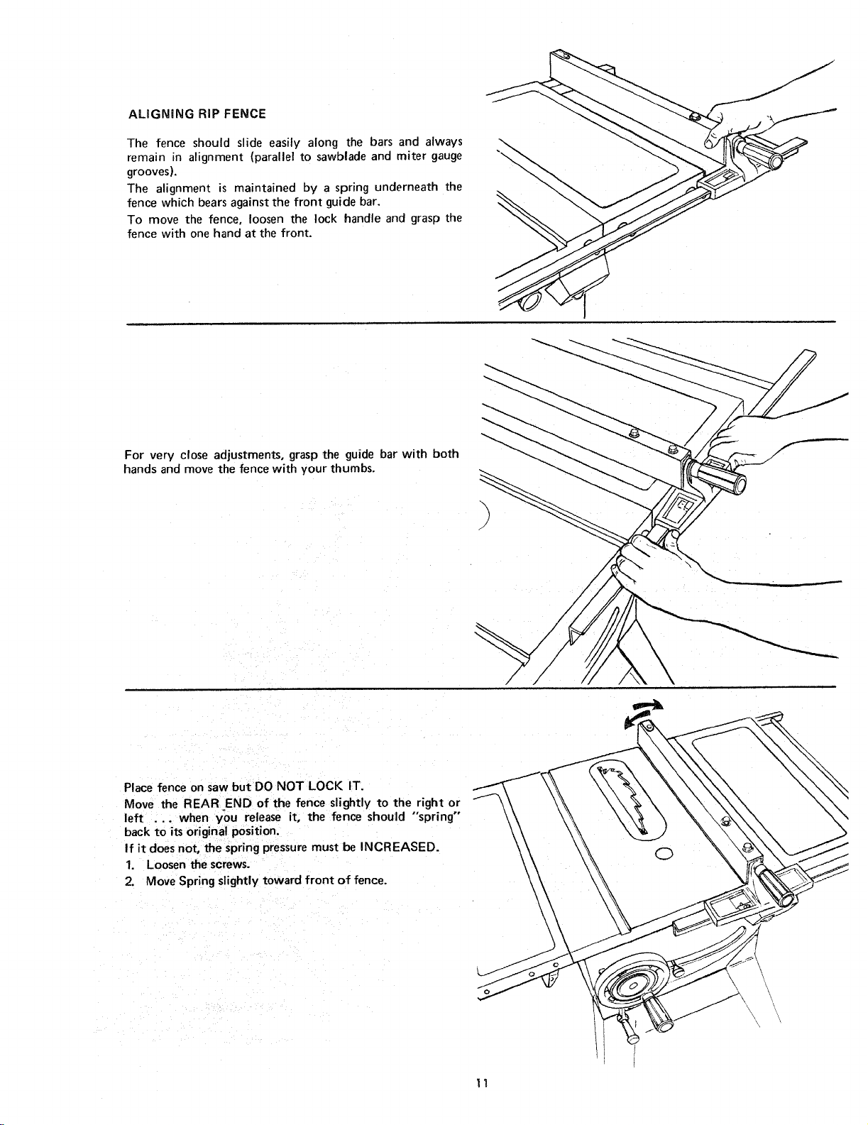
ALiGNiNGRIPFENCE
The fence should slide easily along the bars and always
remain in alignment (parallel to sawblade and miter gauge
grooves).
The alignment is maintained by a spring underneath the
fence which bears against the front guide bar.
To move the fence, loosen the lock handle and grasp the
fence with one hand at the front.
For very close adjustments, grasp the guide bar with both
hands and move the fence with your thumbs.
Place fence on saw but DO NOT LOCK IT,
Move the REAR END of the fence slightly to the right or
left ... when you release it, the fence should "'spring'"
back to its original position.
If it does not, the spring pressure must be INCREASED.
1. Loosen the screws.
2. Move Spring slightly toward front of fence.
/
11

If the fence does notslide easily along the bars. the pressure
of the springcan be R EDUCED.
1. Loosen the screws.
2. Move spring slightly toward rear of fence . .. tighten
screws.
, The rip fence must be PARALLEL with the sawblade
and Miter Gauge grooves ... Move fence until it is
along side of groove. Do NOT LOCK IT. It should be
parallel to groove. If it is not;
A. Loosen the two "Hex. Head Screws."
B. Hold fence head tightly against bar .., move end
of fence so that it isparallel with groove,
C. Alternately tighten the screws.
SPRING
SCREWS _
\\
HEX SCREWS
:E NCE
ADJUSTING RIP SCALE POINTER
1. Turn ELEVATION handwheel clockwise until blade is
up ashigh as it will go.
IMPORTANT: BLADE must be SQUARE |90o| to
TABLE, in order to ALIGN rip fence.
2. Position fence on right side of sawblade so that it
touches the sidesof the teeth.., tighten lock knob.
3. Loosen screw holding the pointer.., adjust pointer so
that ispoints to "0"... tighten screw.
NOTE: If you cannot adjust pointer sothat it points to
"0", loosen the screws holding the front guide bar and
move the guide bar.
INSTALLING BLADE GUARD
1. From amoung the loose parts, find the hardware.
2. Attach SPREADER to SPREADER SUPPORT so that
screws are all the way back in the SLOTS of SUPPO RT
... hand tighten screws,
XLOCK HANDLE _
v4-2ox 5/8 // I_
_ SI_EADER
'_ SUPPORT
12
EXT. I/4
I
NUT, HEX I/4
 Loading...