

Craftsman 113213151 Owner’s Manual

Save ThisManuam _'_
For FutureReference
MODEL NO.
113.213151
DRmLLPRESS WiTH
MAXIMUM DEVELOPED
1 HP MOTOR
Serial
Number
Model and serial number
may be found at the rear
of the head.
You should record both
model and serial number in
a safe place for future use,
FORYOU
SAFETY:
READALL
INSTRUCTIONS
CAREFULLY
MOTORIZED
® assembJy
® operating
e repair parts
Sold by SEARS,ROEBUCK AND COo_Chicago_ _L606_ U.S.A.
Part No, SP5643

GENERAL SAFETY iNSTRUCTiONS FOR POWER TOOLS
t, KNOW YOUR POWER TOOL
R_a<_ atd ur_de_st_rx, _ file tw_er,% r_anuat _uxi
iabeis affixed to the _ooI. Learn ,ts appi_cabor_ and
hm_tatfo_s as w,_Has the spec&c poter_tai hazar(js
pecuha_ to th,_stoo_
2. GROUND ALL TOOLS
[_'_ _X_ _S @u_,;iDDed w£h ?_rl ; _DDrewed {_-c Dnd _C_Of
(:ors-:ar_ u,,3_prona grouP,ping w_)e :)_ua "- l_, rr,r_
duCto_ _ 1R_' cord _< the {]roi._n(rlrtg w_rt: Neve
connect the q_,_,_,nw_re tda lwr, _emn_na!
3. KEEP GUARDS tN PLACE
_r_ wor_ln_ o_(_el af3d tQ [)r(_De[ _c_ju,_ffr11(_r3] ;_[](i
al_qnmen!
4. REMOVE ADJUSTING KEYS AND WRENCHES
FoH'r_ a h_;_t_t (_t checklnq 10 _t'e th_ _. k_:!_'s _rt_l
adiushng wrench_< are removed from too_ before
'_urf!ff'lQ _t Ot*i
5, KEEP WORK AREA CLEAN
CkJ|tered ;_[_3as atwl t)ertchet_ irlvlte accldeflt_, F/col
m_st not t:,_ _.dlppery gue I_o w_x or saw(_ust
6, AVOID DANGEROUS ENVIRONMENT
DeW[ Ugh: power tools _n damp nr wet _ocattor'_s o{
exI:K_s;eth_',m to ram. Keep work area we!l hqhled
Provide adequate surrour_dmg work space}
7. KEEP CHIfLOREN AWAY
A}I v_S_tors should be k_pl a ;;a_e dista_c_:, from
work area
8, _AKE WORKSHOP CHILD-PROOF
W_th padlocks, master sw_tches by remowng star.
_er keys Or Slortng tOOlS where ch4dren can't get
them
9. DON'T FORCE TOOL
it wilI do the _ob better and safer at me rate for
wR_cn _t wa_ designed
10. USE RIGHTTOOL
Don't force too_s or attachm.ent to do a leo _ was
not deslgnea fon
11. WEAR PROPER APPAREL
Do no_ wear loose CtOth_ng gioves necKhes or
lewe_ry ,nngs. wnst watches_ to get caught tn rnov.
_g parts NONSLIP footwear _s recommended
Wear protectwe hair covering to con[am _ong hatr
Roti long sleeves peeve the elbow
12, USE SAFETY GOGGLES (HEAD PROTECTION)
Wear safety goggles [must compty w_tn ANSI
Z871) a! aF t_H_es 8ve, yx!ay eyegh:!_sses a,e not
safety glasses P:ey oniy have mpact resistant
encq.s Aiso use face o_ dust mask ff cutting oper
abon _s dusty and ear ;;_;)t,;ttots (plugs or ¢,Aufis}
cunng ex_encted periods or ope_at:o;s
13. SECURE WORK
L!Sf o_rT,,DS Or a VIS© PC DO/C _ ,%,{-!r_, W_!(_n _tac_(:a .
'_ fie( nov hands tC oDe-a[( [o(;
t4 DON'T OVERREACH
I'_'_'_b_ OtgDer tO()_r_q aqc oah:ince al ai! t_mt)s
15. MAINTAIN TOOLS WITH CARE
_eeD too_s snaq:_ an,(_ c_:an for best and safes.;
;;eqormanc( Follow mstru(;t_or_s for _ubncatmg and
cr,,angir}g accessones
16, DISCONNECT TOOLS
Before serwcmq wber chanqmg accessories such
a_ Modes [)_fs c_dtf_,rs etc
17. AVOID ACCIDENTAL STARTING
Make sure sw_tcn ,_m -OF:I::cos€on before pJug*
grog m
18. USE RECOMMENDED ACCESSORIES
Consun the owner_ manual for recommended ac-
cessones Follow the _nstruct}ons that accompany
the accessones ]he use of ,<[)roPer accessories
may cause hazards
19. NEVER STAND ON TOOL OR ITS STAND
Serious _njury could occur if the too_ is tipped Or _f
the cuthng tool _sacc_den_a_ y contacted. Do not
store matenals above or near me too! such that it
_s necessary to stand on the _oo_ or its stand to
_each them.
20. CHECK DAMAGED PARTS
Before furthe_ use of the [oo_ a guard or other part
that _s damageo should De carefully checked to
ensure that _twdl e_>erate DroDeny and perform its
re[ended function Check for alignment of moving
parrs Dmd_n9 or mowng parrs, breakage of parts.
rnoun[_ng, aria any other COnditions that may affect
its operation. A guara or other part that is damaged
should oe oroDerly reoaired o_ reoiaoed.
21. DIRECTION OF FEED
Feed work into a blade or cutter against the d_rec-
t_on of rotation of the blade or cutter only.
22. NEVER LEAVETOOL RUNNING UNATTENDED
Turn power off. Don't leave tool until it comes to a
complete stop.
additional safety instructions for drim presses
c
o
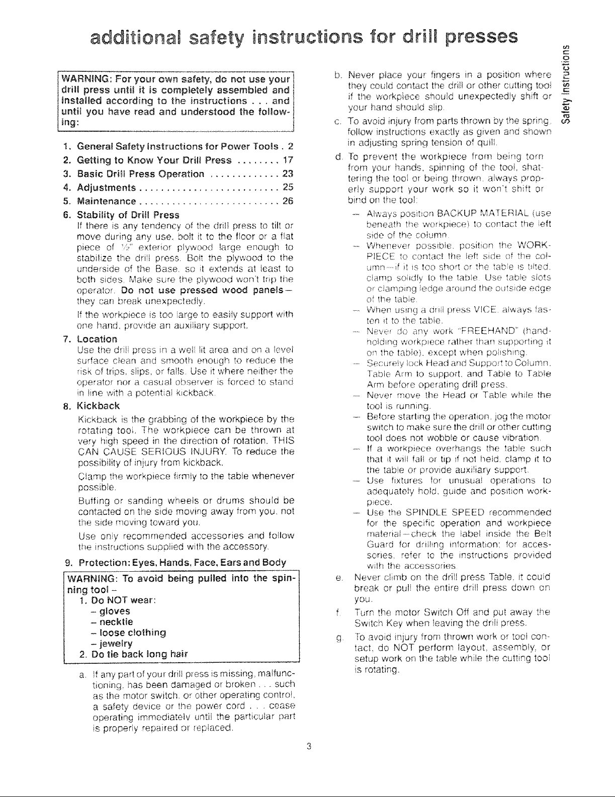
WARNING: For your own safety, do not use your I
drill press unti] it is completely assembled and
installed according to the instructions ° . , and _i
unti_ you have read and understood the follow- I
ing: ]
1. General Safety instructions for Power Too_s, 2
2. Getting to Know Your Drill Press ........ 17
3. Basic Drill Press Operation ............. 23
4. Adjustments .......................... 25
5. Maintenance .......................... 26
6. Stability of Dri_l Press
If there is any tendency of the dril] press to tilt or
move during any use, boit it to the floor or a fiat
piece of !i_" exterior p_ywood _arge enough to
stabilize the drill press Bolt the plywood to the
underside of the Base. so 4t extends at least to
both sides Make sure the plywood won't trip the
operater. Do not use pressed wood panels--
they can break unexpectediy.
If the workpiece is too iarge to easily support with
one hand_ provide an a_xiiary support.
7, Location
Use the dril press in a wei lit area and on a ieve;
surface cfean and smooth enough to reduce the
risk of trips, slips, or falls Use it where neither the
eperator nor a casuat observer is forced to stand
in line with a potent af kickback
8. Kickback
Kickb_ck i._;the grabbing of the workpiece by the
rotating tooi, The workp_ece can be thrown at
very high speed in tI_e d rection of rotation. THIS
CAN CAUSE SERIOUS tNJURY To reduce the
possibility of injury from kickback.
Clamp the workpiece firmly to the table whenever
possible.
Buffing or sanding wheeis or drums should be
contacted on the side moving away from you, not
the side moving toward you.
Use oniy recommended accessories and follow
the instructions supplied with the accessory.
9. Protection: Eyes, Hands, Face, Ears and Body
WARNING: To avoid being pulled into the spin-
ning too] -
1, Do NOT wear:
- g_oves
- necktie
- loose clothing
- jewetry
2. DO tie back tong hair
If any part of your drill p_ess is missing malfunc-
tioning, has been damaged or broken .... such
as the motor switch, or other operating centre!,
a safety device or the power cord . . . cease
operating immediateiv until the particular pa_t
is properly repaired or _epiaced.
b Never p_ace your fingers in a position where
they could contact the drill or other c_ttir_g tooi
if the workpiece should unexpectedly shift or
your hand sho_id slip
c. To avoid injury from parts thrown by the spring
follow instRJctions exactly as given and shown
in adjusting spring tension of quiti.
d [0 preverit the workpiece from being tom
flora your hands, spinning of the tooi, shat
tering the tooi or being thrown, always prop-
erly support your work so it won't shift or
b;nd or_ the tool:
..-.- Always posit_on BACKUP MATERIAL use
beneath the workpiece} to cortact the eft
side of _he ce_umn
-- Whenever possible, position the WORK-
PIECE to contac! lhe ieft side of the c,_:_l-
ufnn if it iS tOO short or the tabe _st_/ted
claret:) soiidiy I(:)the table Use tabe slots
or (s/amp ng ledge around the o_ts de edge
of the table
.... When us_ngadriilpressViCE awaysfas-
ten _[ to the tabie.
..... Neve_ do any work "FREEHAND" (hand-
ilo}d_ng workp_ece rather tf-'a_ suppo_ti_g t
on the tab e). except when poiishi_g
- Secu_e!y lock ;'-lead ar)d Support to Co!utah.
J-able Arrn tO support, and Table to "[abe
Arm before operating driiI press.
-- Never move the Head or Table whJle the
too} is running.
-_- Before starting the operation, jog the moto_
switch tO make sure the dritl or other cutting
tool does not wobbie or cause vibration
•_-. If a workpieee overhangs !he _ab!e such
that it wili fali or tip if not hefd clamp it to
the tab]e or provide auxiliary supper1
--o Use fixtu{es for uNusuai operations to
adequately hofd, guide and position work-
p_ece.
-_ Use the SPINDLE SPEED recommended
for the specific operation and workpiece
material--check the iabei inside the Belt
Guard for driihng information: for acces-
series, refer to the instructions provided
wilh the accessories
e. Never climb on the drill press Table it couid
break or put! the entire drili press down ors,
you
f Turn the motor Switch Off and put away the
Switch Key when !eaving the dril press.
g to avoid injury from thrown work o_ tool con.-
tact do NOT perform _ayout assembly, or
setup work on the table wh]e the c_xtt_ngtooi
is rotating.
/( i ¸¸
i! iiiiii!i!iii iii:i i!iiiiil) !i i ii ii)ii !ii ! i i , :ili i Iii!iiii i : !ii i : !ililiiii : ! i iiii i ii i:
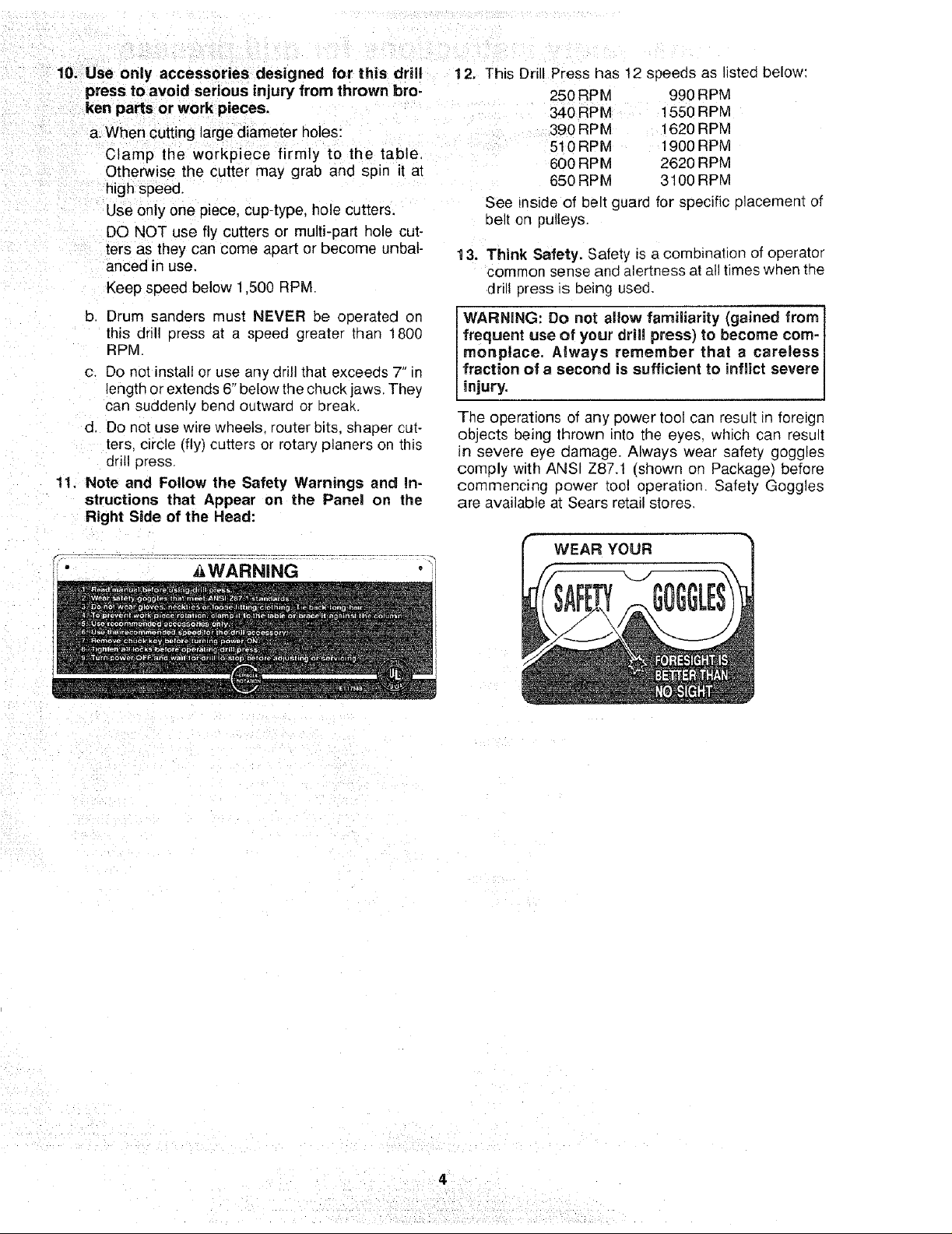
10i Use °nly accessories designed for this drill 121 This Drill Press has 12 speeds as listed below:
Press to avoid se!ious injury from thrown bro; 250 RPM 990 RPM
pa_s or work pieces. 340 RPM i 550 RPM
cutting large dlameter holes: 390 RPM 1620 RPM
the workpiece iirmly to the tablel 510RPM 1900RPM
Otherwise the cutter may grab and spin it at
high speed.
Use only one piece, Cup-type, hole cutters.
DO NOT use fly cutters or multi-part hole cut-
: ters as they can come apart or become unbal-
anced in use.
Keep speed below 1,500 RPM.
b. Drum sanders must NEVER be operated on
this drill press at a speed greater than 1800
RPM.
c. Do not install or use any drill that exceeds 7" in
length or extends 6" below the chuck jaws, They
can suddenly bend outward or break.
d, Do not use wire wheels, router bits, shaper cut-
ters, circle (fly) cutters or rotary planers on this
drill press.
11_ Note and Follow the Safety Warnings and in-
structions that Appear on the Panel on the
Right Side of the Head:
See inside of belt guard for specific placement of
belt on pulleys.
13. Think Safety. Safety is a combination of operator
common sense and alertness at all times when the
drill press is being used.
WARNING: Do not allow familiarity (gained from]
frequent use of your drill press) to become com- I
monplace. Always remember that a carelessJ
fraction of a second is sufficient to inflict severe I
injury, j
The operations of any power tool can result in foreign
objects being thrown into the eyes, which can result
in severe eye damage. Always wear safety goggles
comply with ANSI Z87.t (shown on Package) before
commencing power tool operation. Safety Goggles
are available at Sears retail stores.
600 RPM 2620 RPM
650 RPM 3100 RPM
i " _WARNING
WEAR YOUR
gmessary of terms
1. Workpiece
The item on which the cutting operations is being
performed.
2. Drill
The cutting tool used in the drill press to make holes
in a workpiece,
3. Backup Material
A piece of wood placed between the workpiece and
table .... it prevents wood in the workpiece from
splintering when the drill passes through the back-
side of the workpiece .... also prevents drilling into
the table top.
table of contents
Page
General Safety Instructions for Power Tools ...... 2
Additional Safety Instructions for Drill Presses .... 3
Glossary of Terms .......................... 5
Table of Contents ........................... 5
Motor Specifications and Electrical
Requirements .............................. 6
Unpacking and Checking Contents ............. 7
Table of Loose Parts ........................ 8
Location and Function of Controls .............. 9
Assembly ................................ 10
Assembly of Column and Table Hardware... 10
Installing the Table ..................... 11
Installing the Head ..................... 11
Mounting Motor ........................ 12
Installing Motor Pulley ................... 12
Tensioning Belt ........................ 12
Installing Belt Guard Knob ............... 13
Motor Connections ..................... 14
Installing Feed Handles ................. 14
Installing the Chuck ..................... 14
Installing Light Bulb ..................... 16
4. Revolution Per Minute (R.P.M.)
The number of turns completed by a spinning object
in one minute.
5, Spindle Speed
The RPM of the spindle,
_E
Page
Adjusting the Table Square to Head ....... 16
Bevel Scale ........................... 16
Getting to Know Your Drill Press .............. 17
On-Off Switch ......................... 19
Drilling to a Specific Depth ............... 20
Locking Chuck Desired Depth ............ 20
Removing Chuck and Arbor .............. 21
Re-Installing the Chuck and Arbor ......... 22
Basic Drill Press Operation .................. 23
Installing Drills ......................... 23
Positioning Table and Workpiece .......... 24
Tilting Table ........................... 25
Hole Location ......................... 25
Feeding .............................. 25
Adjustments .............................. 25
Quill Return Spring ..................... 25
Maintenance .............................. 26
Lubrication ............................... 26
Recommended Accessories .................. 26
Trouble Shooting .......................... 27
Repair Parts .............................. 28
motor specificationsand emectricam
requirements
o pE nCAT O.s
This drill press is designed to use a 1725 RPM motor
only, Do not use any motor that runs faster than 1725
RPM It is wired for operation on 110-120 volts. 60 Hz.
alteinat ng current.
WARNING: To avoid injury from unexpected
startup, do not use blower or washing machine I
motors or any motor with an automatic reset I
overload protector.
CONNECTING TO POWER
SOURCE OUTLET
This machine must be grounded while in use to protect
the operator from electric shock.
Plug power cord into a 110-120V properly grounded
type outlet protected by a 15-amp. dual element time
delay or Circuit breaker.
Not all outlets are properly grounded. If you are not
sure that your outlet, as pictured below, is properly
grounded, have it checked by a qualified electrician.
WARNING: To avoid electric shock, do not touch I
the metal prongs on the plug, when installing or
removing the plug to or from the outlet.
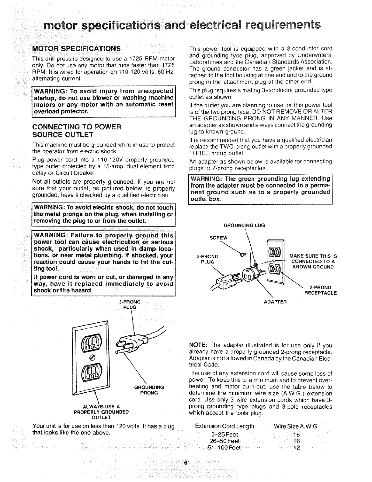
Th!s powe_ too! is equipped with a 3-conductor cord
and grounding type plug, approved by Underwriters'
Laboratories and the Canadian Standards Association.
The ground conductor has a green jacket and is at-
tached to the toot housing at one end and to the ground
prong in the attachment plug at the other end.
This plug requires a mating 3-conductor grounded type
outlet as shown,
if the outlet you are planning to use for this power tool
isof the two prong type, DO NOT REMOVE OR ALTER
I
THE GROUNDING PRONG IN ANY MANNER. Use
an adapter as shown and always connect the grounding
lug to known ground.
It is recommended that you have a qualified electrician
replace the TWO prong outlet with a properly grounded
THREE prong outlet.
An adapter as shown below is available for connecting
plugs to 2-prong receptacles,
WARNING: The green grounding lug extending 1
from the adapter must be connected to a perma- t
nent ground such as to a proper_y grounded
outlet box.
GROUNDING LUG
WARNING! Failure to properly ground this
I
power tool can cause electrmution or serious
shock, particularly when used in damp loca-
tions, or near metal plumbing;if shocked, your
reaction could cause your hands tohit the cut-
ring tool.
'if power cord is worn or cut, or damaged in any
Way, have it replaced immediately to avoic
shock or fire hazard.
3-PRONG
PLI IG
NOTE: The adapter illustrated is for use only if you
already have a properly grounded 2-prong receptacle.
Adapter is not allowed in Canada by the Canadian Elec-
trical Code.
The use of any extension cord will cause some loss of
power. To keep this to a minimum and to prevent over-
heating and motor burn-out, use the table below to
determine the minimum wire size (A.W.G) extension
cord. Use only 3 wire extension cords which have 3-
ALWAYS USE A
PROPERLY GROUNDED
OUTLET
Your unit is for use on less than 120 volts. It has a plug Extension Cord Length Wire Size A.W.G
that looks like the one above, 0-25 Feet 16
prong grounding type plugs and 3-pole receptacles
which accept the tools plug.
SCR_,,., \
3-PRONG _ _ MAKE SURE THIS IS
ADAPTER
2_50 Feet 16
5i-100 Feet 12
unpacking and checking contents
WARNING: To avoid injury from unexpected
starting or electrical shock, do not pmugthe
power cord into a source of power. This cord
must remain unpJugged whenever you are work-
ing on the drill press.
Model 113.213151 Drill Press is shipped complete in
one box.
1. Unpacking and Checking Contents
a. Separate all "loose parts" from packaging mate-
rials and check each item with "Table of Loose
Parts" to make sure all items are accounted for,
before discarding any packing material.
WARNING: if any parts are missing, do not I
attempt to assemble drill press, plug in the I
power cord, or turn the switch on until the miss- I
ing parts are obtained and are instamled correct- I
[Y" J
2. Remove the protective oil that is applied to the
table and column. Use any ordinary household type
grease and spot remover.
WARNING: To avoid fire or toxic reaction, never
use gasoline, naptha or similar highly volatile
so vents.
3. Apply a coat of paste wax to the table and column
to prevent rust. Wipe all parts thoroughly with a clean
dry cloth.
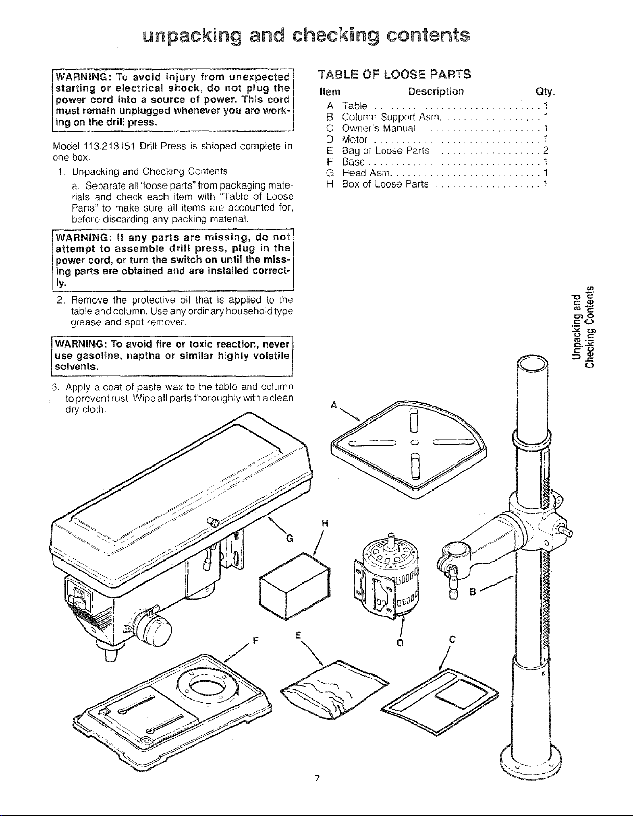
TABLE OF LOOSE PARTS
gtem Description City.
A Table .............................. 1
B Column Support Asm .................. 1
C Owner's Manual ...................... 1
D Motor .............................. 1
E Bag of Loose Parts ................... 2
F Base ............................... 1
G Head Asm ........................... 1
H Box of Loose Parts ................... 1
A
°/
H
D
C
A
\ A
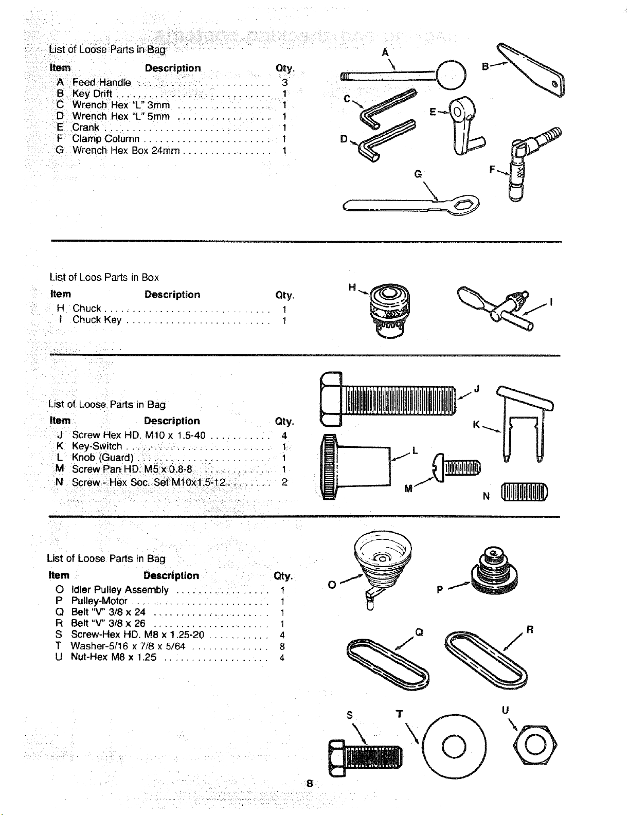
,i_iii_iI'_ _ It_r_ Descr _p_ior_ _ Oty, __ __P _
A FeedHandle ::. : i.i:i:i..i... 3 _--- -- -'_
B Key Drift.,. , : ; .......... 1
C WrenchHex "L',3mm'''', ...: .... .i:...i:, 1 C,,_,-
D Wrench Rex"L 5mm ,.i: ...... :..:..i 1
E Cranki. ........... i: ..... i.,::..., i
F Clamp Column ............... i ...... : 1 D_,_
G Wrench Hex Box 24rnrn ................ 1
G
List of Loos Parts in Box
Item Description Qty.
H Chuck .............................. 1
I Chuck Key .......................... 1
i
!
List of Loose Parts in Bag
item Description Qty.
J Screw Hex HD. M10 x 1.5-40 ........... 4
K Key-Switch., ._.., ................. 1
L Knob (Guard) : .................... 1
,!
List of Loose Parts in Bag
Item Description Qty.
O idler Pulley Assembly ........ .... i. ,. 1
P Pulley-Motor ......................... 1
Q Belt "V" 3/8 x 24 ..................... 1
R Belt "V" 3/8 x 26 ..................... 1
S Screw-Hex HD. M8 x 1.25-20 ........... 4
T Washer-5/16 x 7/8 x 5/64 .............. 8
U Nut-Hex M8 x 1.25 ................... 4
J
J
N
_ _ _i i _ i _ _ i _
$
8
T U
ooation and function of controls
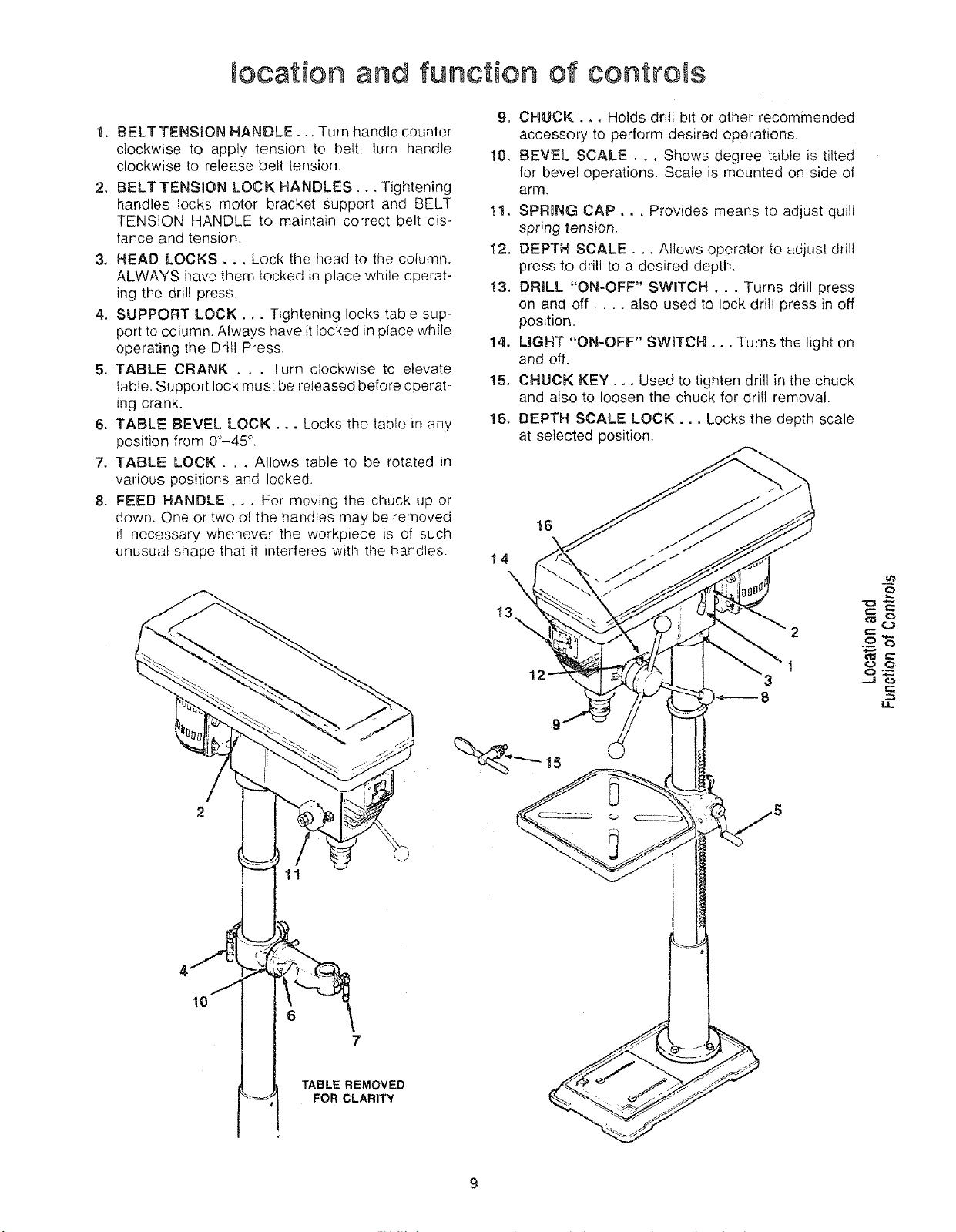
1. BELTTENSION HANDLE... Turn handle counter
clockwise to apply tension to belt, turn handle
clockwise to release belt tension.
2. BELT TENSION LOCK HANDLES... Tightening
handles locks motor bracket support and BELT
TENSION HANDLE to maintain correct belt dis-
tance and tension.
3. HEAD LOCKS, ., Lock the head to the column.
ALWAYS have them locked in place while operat-
ing the drill press.
4. SUPPORT LOCK... Tightening locks table sup-
port to column. Always have it locked in place while
operating the Drill Press.
5. TABLE CRANK . . . Turn clockwise to elevate
table. Support lock must be released before operat-
ing crank.
6. TABLE BEVEL LOCK... Locks the table in any
position from 0"-45 °
7. TABLE LOCK... Allows table to be rotated in
various positions and locked.
8. FEED HANDLE . . . For moving the chuck up or
down. One or two of the handles may be removed
if necessary whenever the workpiece is of such
unusual shape that it interferes with the handles.
9. CHUCK... Holds drill bit or other recommended
accessory to perform desired operations,
10, BEVEL SCALE . .. Shows degree table is tilted
for bevel operations. Scale is mounted on side of
arm.
11. SPRUNG CAP,.. Provides means to adjust quill
spring tension.
12. DEPTH SCALE... Allows operator to adjust drill
press to drill to a desired depth.
13. DRILL "ON-OFF" SWITCH ... Turns drill press
on and off .... also used to lock drill press in off
position.
14. LIGHT "ON-OFF" SWITCH... Turns the light on
and off.
t5. CHUCK KEY... Used to tighten drill in the chuck
and also to loosen the chuck for drill removal.
16, DEPTH SCALE LOCK.., Locks the depth scale
at selected position.
16
14
10
P
13
0:._.
Q
Q
£::::
6
7
TABLE REMOVED
FOR CLARITY
assembly
IWARNiNG: For your own safety, never connect
l plug to power source outlet until all assembly
I steps are completed.
- TOOLS NEEDED ......................
COMBINATION
SQUARE
MEDIUM 8-iNCH ADJUSTABLE
SCREWDRIVER WRENCH
-- 03
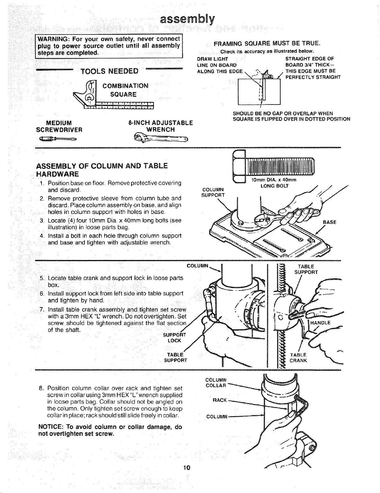
ASSEMBLY OF COLUMN AND TABLE
HARDWARE
1. Position base on floor, Remove protective covering
and discard
2. Remove protective sleeve from column tube and
discard. Place column assembly on base. and aligr
holes in column support with holes Ln oase,
3, Locate (4) four lOmm Di& x 40mm long bolts (see
illustration) in loose parts bag.
4, Install a bolt in each hole through column support
and base and tighten with adjustable wrench.
FRAMING SQUARE MUST BE TRUE.
Check its accuracy as illustrated below.
DRAW LIGHT
LINE ON BOARD
EDGE '_',
ALONG THIS X,,,.__ ,_ //
J
SHOULD BE NO GAP OR OVERLAP WHEN
SQUARE IS FLIPPED OVER IN DOTTED POSiTiON
1Omm DIA. x 40rnm
COLUMN LONG BOLT / _," /
STRAIGHT EDGE OF
BOARD 3/4" THICK--
THIS EDGE MUST BE
PERFECTLY STRAIGHT
soPpO.T . f /
5. Locate table crank and support lock in loose parts
bOX,
6. Install support lock from left side into table support
and tighten by hand.
7. Install table crank assembly and tighten set screw
with a 3mm HEX "E'wrench, Do not overtighten. Set
screw should be tightened against the flat section
of the shaft.
SUPPORT
LOCK
TABLE
SUPPORT
8. Position column collar over rack and tighten set
screw in collar using 3rnm HEX "L" wrench supplied
in loose parts bag. Collar shou d not be angled on
the column. Only tighten set screw enough to keep
collar _nplace: rack should still slide freely in collar
NOTICE: To avoid column or collar damage, do
not ovettighten set screw.
COLUMN
=L__/PTABLE
PORT
COLUMN
COLUMI
10
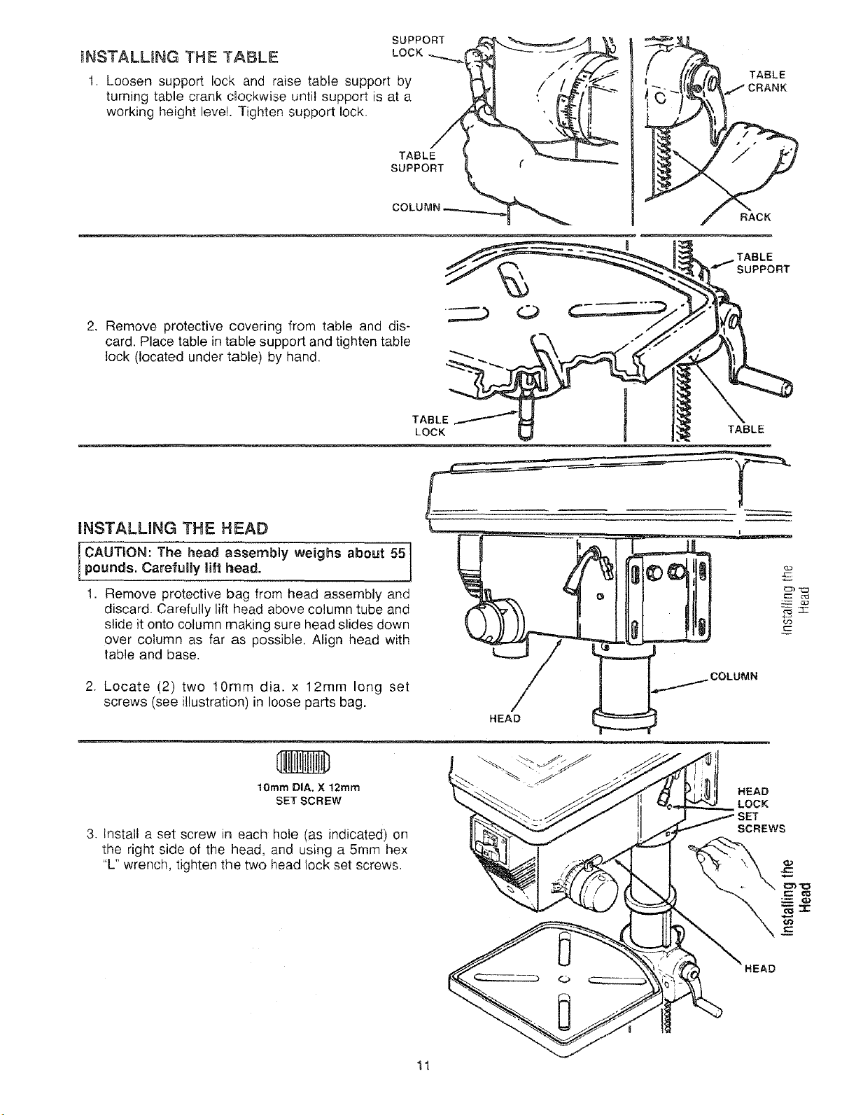
INSTALLING THE TABLE
t. Loosen support lock and raise table support by
turning table crank cRockwise until support is at a
working height level. Tighten support lock.
Remove protective covering from table and dis-
card. Place table in table support and tighten table
lock (located under table) by hand.
SUPPORT
LOCK
TABLE
SUPPORT
TABLE t
LOCK TABLE
TABLE
RACK
TABLE
SUPPORT
mNSTALLING THE HEAD
[ CAUT'ON: The head assembly weighs about 551
pounds, Carelully lift head.
1. Remove protective bag from head assembly and
discard. Carefully lift head above column tube and
slide it onto column making sure head slides down
over column as far as possible, Align head with
table and base.
2. Locate (2) two lOmm dia. x 12ram long set
screws (see illustration) in loose parts bag.
lOmm DIA. X 12mm "
SET SCREW
3. Install a set screw in each hole (as indicated) on
the right side of the head, and using a 5mm hex
"L" wrench, tighten the two head lock set screws.
.i_; _ f
HEAD
LOCK
11
 Loading...