

Craftsman 113213130 Owner’s Manual

//_ Save This Manual "_
For Future Reference
MODEL NO.
'_!3.2'13!30
DRILL PRESS WITH
MAXIMUM DD!ELOPED
2/3 HP MOTOR
Serial
Number
Model and serial number
may be found at the rear of
the head.
You should record both
model and serial number in
a safe place for future use,
l lll
CAUTION:
READ ALL
iNSTRUCTIONS
CAREFULLY
MOTORIZED
I
EL
e assembly
e operating
• repair parts
,L Pl
x,..
Part No. SP5186
Sold by SEARS, ROEBUCK AND CO., Chicago, tL 60684 U.S.A.
Printed in ÷_;, _"_,_
FULL ONE YEAR WARRANTY ON CRAFTSMAN DRILL PRESS
If within one year from the date of purchase, this Craftsman Drill Press fails due to a defect
in material or workmanship, Sears will repair it, free of charge.
WARRANTY SERVICE IS AVAILABLE BY SIMPLY CONTACTING THE NEAREST SEARS SER-
ViCE CENTER!DEPARTMENT THROUGHOUT THE UNITED STATES.
This warranty applies only while this product is used in the United States.
This warranty gives you specific legal rights, and you may also have other rights which
vary from state to state.
SEARS, ROEBUCK AND CO., Dept. 698/73tA, Sears Tower, Chicago, IL 60684
GENERAL SAFETY INSTRUCTmONS FOR POWER TOOLS
1. KNOW YOUR POWER TOOL
Read and understand the owner's manual and
labels affixed to the tool, Learn its application and
fimkations as welt as the specific potential hazards
pecuiiar to th{s tool,
2. GROUND ALL TOOLS
Thistoolisequippedwithan approved3-conductor
cord and a 3-prong grounding tyoe pIug to fit the
proper grounding type receptacle, The green con-
ductor in the cord is the groundin 9 wire Never
connect the green wire to a live terminal.
3. KEEP GUARDS IN PLACE
in working order, and in proper adjustment and
alignment.
4. REMOVE ADJUSTING KEYS AND WRENCHES
Form a habit of checking to see that keys and
adjusting wrenches are removed from tool before
turning it on.
5. KEEP WORK AREA CLEAN
Cluttered areas and benches invite accidents. Floor
must not be slippery due to wax or sawdust,
6. AVOID DANGEROUS ENVIRONMENT
Don't use power tools in damp or wet locations or
expose them to rain. Keep work area well lighted.
Provi(_e adequate surrounding work space.
7. KEEP CHILDREN AWAY
A_tvisitors should be kept a safe distance from
work area.
8. MAKE WORKSHOP CHILD-PROOF
With padlocks, master switches, by removing star-
ter keys, or storing tools where children can't get
them,
9. DON'T FORCE TOOL
It will do the job better and safer at the rate for
which it was designed,
10. USE RIGHTTOOL
Don_tforce tools or attachment to do a job it w&s
not designed for,
11. WEAR PROPER APPAREL
Do not wear loose clothing, gloves, neckties, or
jewelry (rings, wrist watches) to get caught in mov-
ing parts. NONSLtP footwear is recommended.
Wear protective hair covering to contain long hair.
Rolt long sleeves above the elbow.
12. USE SAFETY GOGGLES (HEAD PROTECTION)
Wear safety goggles (must comply with ANSI
Z87.1) at al! times. Everyday eyeglasses are not
safety glasses, They only have impact resistant
ienses. Also, use face or dust mask if cutting oper-
ation is dusty, and ear protectors (plugs or muffs)
during extended periods of operation.
13. SECURE WORK
Use clamps or a vise to hold work when practical
It frees both hands to operate tool.
14. DON"I" OVERREACH
Keep proper foobng and balance at aft times,
15. MAINTAIN TOOLS WiTH CARE
Keep tools sharp and clean for best and safest
performance. Follow instructions for lubricating and
changing accessories.
16. DISCONNECT TOOLS
Before servicing;when changing accessories such
as blades, bits, cutters, etc.
17. AVOID ACCIDENTAL STARTING
Make sure switch is in "OFF" position before plug-
ging in.
18. USE RECOMMENDED ACCESSORIES
Consult the owner's manual for recommended ac-
cessories. Follow the instructions that accompany
the accessories, The use of improper accessories
may cause hazards.
19. NEVER STAND ON TOOL OR ITS STAND
Serious injury could occur if the tool is tipped or if
the cutting tool is accidentally contacted. Do not
store rnatenais above or near the tool such that it
is necessary to stand on the tool or its stand to
reach them.
20. CHECK DAMAGED PARTS
Before further use of the too!, a guard or other part
that is damaged should be carefully checked to
ensure that it will operate properly and perform its
_ntended function, Check for alignment of moving
parts, binding or moving parts, breakage of parts,
mounting, and any other conditions that may affect
its operation. A guard or other part that is damaged
should be properly repaired or replaced.
21. DIRECTION OF FEED
Feed work into a blade or cutter against the direc-
tion of rotation of the blade or cutter only.
22. NEVER LEAVETOOL RUNNING UNATTENDED
Turn power off Don't teave too! until it comes to a
complete stop.
additional safety instructions for drill presses
WARNING: FOR YOUR OWN SAFETY, DO NOT
USE YOUR DRILL PRESS UNTIL mT IS COM-
PLETELY ASSEMBLED AND INSTALLED ACCORD-
ING TO THE INSTRUCTIONS... AND UNTIL YOU
HAVE READ AND UNDERSTAND THE FOLLOW-
iNG:
1. General Safety Instructions for Power Tools. 2
2. Getting to Know Your Drill Press ........ 17
3. Basic Drill Press Operation ............. 22
4. Adjustments .......................... 24
5. Maintenance .......................... 25
6. Stability of Drill Press
If there is any tendency of the drill press to tilt or
move during any use, bolt it to the floor or a flat
piece of W" exterior plywood large enough to
stabilize the drill press. Bolt the plywood to the
underside of the Base, so it extends at least to
both sides, Make sure the plywood won't trip the
operator. Do not use pressed wood panels
they can break unexpectedly.
If the workpiece is too large to easily support with
one hand, provide an auxiliary support.
7. Location
Use the drill press in a well tit area and on a leve!
surface clean and smooth enough to reduce the
risk of trips, slips, or faIts, Use it where neither the
operator nor a casual observer is forced to stand
in line with a potential kickback.
8. Kickback
A kickback occurs when the workpiece is suddenly
thrown in the OPPOSITE direction to the DIREC-
TION OF FEED: THIS CAN CAUSE SERIOUS IN-
JURY. Kickbacks are most commonly caused by
use of accessories NOT recommended for this tool,
9. Protection: Eyes, Hands, Face, Earsand Body
WARNING: TO AVOID BEING PULLED INTO
THE SPINNING TOOL --
1. Do NOT wear:
-- gloves
necktie
-- loose clothing
-- jewelry
2. Do tie back long hair
a. If any partofyourdrill press _smissing, malfunc-
tioning, has been damaged or broken.., such
as the motor switch, or other operating control
a safety device or the 0ower cord . cease
operating immediately until the particular part
is properly repaired or replaced.
b. Never place your fingers in a position where
they could contact the drill or other cutting tool
if the workpiece should unexpectedly shift or
your hand should slip,
c. To avoid injury from parts thrown by the spring,
follow instructions exactly as given and shown
in adjusting spring tension of quill.
d. To prevent the workpiece from being
torn from your hands, spinning of the
tool, shattering the too/or being thrown,
always properly support your work so
it won't shift or bind on the toot:
-- Always position BACKUP MATERIAL (use
beneath the workpiece) to contact the left
side of the column.
-- Whenever possible, position the WORK-
PIECE to contact the left side of the col-
umn-if it is too short or the table is tilted,
clamp solidly to the table. Use table slots
or clamping ledge around the outside edge
of the table.
-- When using a drill press VICE, always fas-
ten it to the table.
-- Never do any work "FREEHAND" (hand-
holding workpiece rather than supporting it
on the table), except when polishing.
-- Securely lock Head and Support to Column,
Table Arm to support, and Table to Table
Arm before operating drill press.
-- Never move the Head or Table while the
tool is running.
-- Before starting the operation, jog the motor
switch to make sure the drill or other cutting
toot does not wobble or cause vibration.
-- If a workpiece overhangs the table such
that it will fall or tip if not held, clamp it to
the table or provide auxihary support.
-- Use fixtures for unusual operations to
adequately hold, guide and position work-
piece.
-- Use the SPINDLE SPEED recommended
for the specific operation and workpiece
material--check the label inside the Belt
Guard for drilling information; for acces-
sories, refer to the instructions p_ovided
with the accessories.
f. Never climb on the drill press Table, it
could break or pull the entire drill press
down on you.
g. Turn the motor Switch Off and put away
the Switch Key when leaving the drilt
press.
h To avoid injury from thrown work ortool
contact, do NOT perform layout, as-
sembly, or setup work on the table wNe
the cutting tool is rotating.
10. Use only accessories designed for this
drill press to avoid serious injury from
thrown broken parts or work pieces,
a Holesaws must NEVER be operated on
this drill press at a speed greater than
400 RPM.
_:_ Dum NEVER be operated on
ths dd pi'e_ at a _ed g_eater than t800
RPM
c Do _ot inStait o_ ,,,_seany driP!that exceeds 7" in
engt_ 0 e×te_tds 6!t'below the Chuck aws. They
car_ S_dden_y be_d outward o_ break,
d Do not Use Wire wheets, _outer bits shaper cut-
ters circle ffly}: cutters Or rotary ptaners on this
1!_ Note and Follow the Safety Warnings and In-
structions that Appear on the Panell on the Left
Side of the Head:
FOR YOUR OWN SAFETY:
Know This Toot! Read and Understand Owner's _anuai before Using this Machine.
Use Recommended Drill Speed_See Chart inside Puitey Cover.
= Always wear safety goggles that comply
with ANSI Z87,1.
mDo not wear gloves, necktie or loose
clothing, Tie back long hair.
mSecurely clamp work to table if it is too
short to contact the column when in
operating position.
12, Th_s Dd_t Press has 5 speeds as hsted below:
500 RPM
990 RPM
1500 RPM
2250 RPM
3100 RPM
See inside of belt guard for specific p_acernent of
beit on puiteys
t3. Think Safety. Safety is a combination of operator
common sense and alertness at all times when the
dr_li press is being used.
WARNING: DO NOT ALLOW FAMILIARITY (GAINED
FROM FREQUENT USE OF YOUR DRILL PRESS)
TO BECOME COMMONPLACE. ALWAYS RE-
MEMBER THAT A CARELESS FRACTION OF A
SECOND tS SUFFICIENT TO INFLICT SEVERE
INJURY.
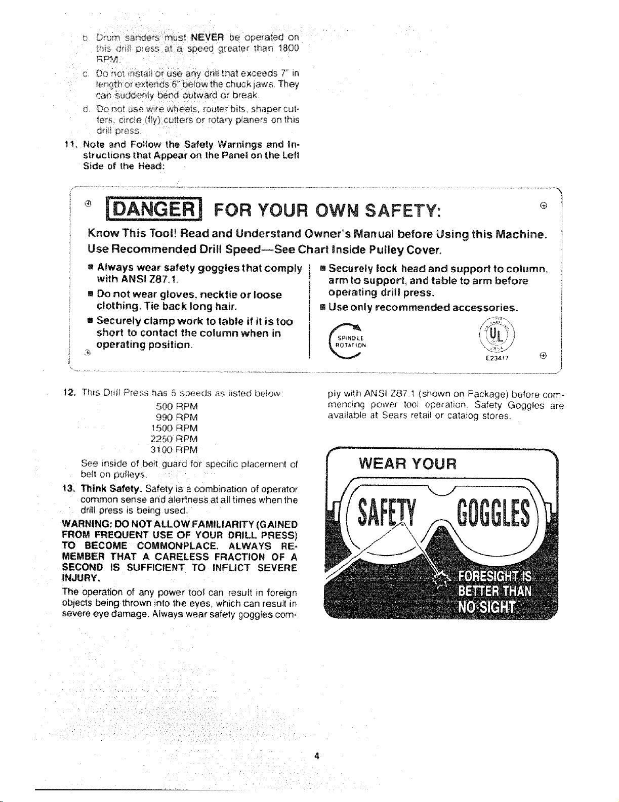
The operation of any power tool can result in foreign
objects being thrown into the eyes. which can result Rn
severe eye damage. Always wear safety goggles corn-
a Securely took head and support to column,
arm to support, and table to arm before
operating drill press.
mUse only recommended accessories.
p!y with AK_S! Z87 1 (shown on Package) before corn-
rnencing power tool operation. Safety Goggles are
avai!able at Sears retail or catatog stores.
gaossary of terms
1. Workpiece
The item or_ which the cutti_'_g operations is being
performed.
2. Drill
The cutting tool used in the drii_ press to make hotes
in a workpiece.
3. Backup Material
A piece of wood placed between the workpiece and
table .... it prevents wood in the workpiece from
splintering when the dril! passes through the back--
side of the workpiece .... also prevents drilling into
the table top
table of
Page
General Safety Instructions for Power Toots ...... 2
Additional Safety Instructions for Drill Presses .... 3
Glossary of Terms .......................... 5
Table of Contents .......................... 5
Motor Specifications and Electrical
Requirements .............................. 6
Unpacking and Checking Contents ............. 7
Table of Loose Parts ........................ 8
Location and Function of Controls ............. 9
Assembly ................................ 10
Assembly of Column and Table Hardware... 10
Installing the Table ..................... 11
Installing the Head .................... 11
Mounting Motor ........................ 12
Installing Motor Pulley ................... 12
Tensioning Belt ........................ 12
Installing Belt Guard Knob ............... 13
Motor Connections ..................... t 4
Installing Feed Handles ................. 14
Installing the Chuck ..................... 14
4. Revolution Per Minute (R.P.M.)
]he number of turns ,,:ompleled by a sp_nn_ng object
in one minute
5. Spindle Speed
The RPM of the spindie.
contents
Page
Adjusting the Table Square to Head ....... 16
Bevel Scale .......................... ! 6
Getting to Know Your Drill Press .............. 17
On-Off Switch ......................... I g
Drilling to a Specific Depth ............... 20
Locking Chuck Desired Depth ............ 20
Removing Chuck ...................... 21
Basic Drill Press Operation .................. 22
Installing Drills ......................... 22
Positioning Table and Workpiece ......... 23
Tilting Table ........................... 24
Hole Location ........................ 24
Feeding ............................. 24
Adjustments .............................. 24
Quill Return Spring ................... 24
Maintenance .............................. 25
Lubrication .............................. 25
Recommended Accessories .................. 25
Troubie Shooting .......................... 26
Repair Parts .............................. 27
motor specifications electrical
i,
MOTOR SPECiFICATiONS
ThiS drili press is designed to use a 1725 RPM motor
only. Do not use any motor that runs faster than t725
RPM, It is wired for operation on 1t0-120 volts, 60 Hz.
alternating current.
WARNING: TO AVOID INJURY FROM UNEX-
PECTED STARTUP, DO NOT USE BLOWER OR
WASHING MACHINE MOTORS OR ANY MOTOR
WiTH AN AUTOMATIC RESET OVERLOAD PRO-
TECTOR.
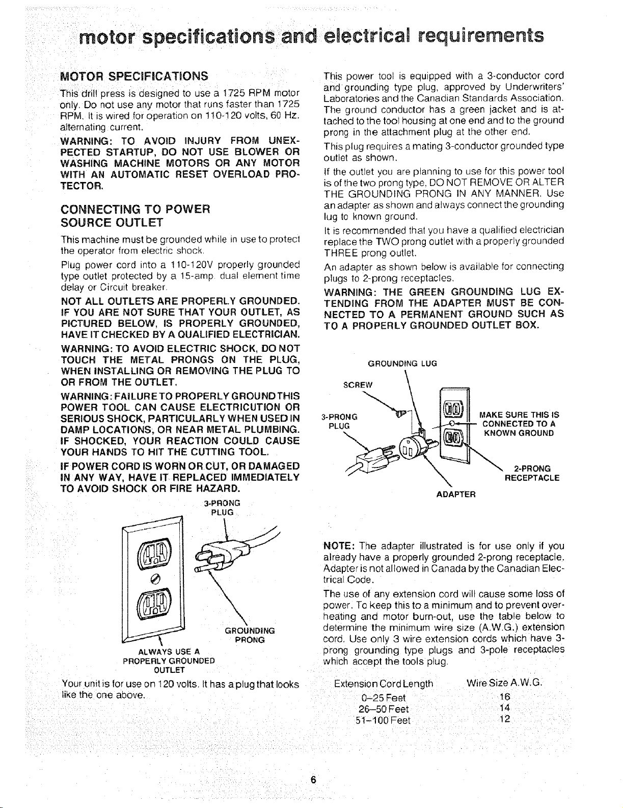
This power tool is equipped with a 3-conductor cord
and grounding type plug, approved by Underwriters'
Laboratories and the Canadian Standards Association.
The ground conductor has a green jacket and is at-
tached to the tool housing at one end and to the ground
prong in the attachment plug at the other end.
This plug requires a mating 3-conductor grounded type
outlet as shown.
If the outlet you are planning to use for this power tool
is of the two prong type, DO NOT REMOVE OR ALTER
requirements
THE GROUNDING PRONG IN ANY MANNER. Use
CONNECTING TO POWER
SOURCE OUTLET
an adapter as shown and always connect the grounding
lug to known ground.
It is recommended that you have a qualified electrician
This machine must be grounded while in use to protect
the operator from electric shock,
Plug power cord into a 110-120V properly grounded
type outlet protected by a 15-amp dual element time
deiay or Circuit breaker.
NOT ALL OUTLETS ARE PROPERLY GROUNDED.
IF YOU ARE NOT SURE THAT YOUR OUTLET, AS
PICTURED BELOW, IS PROPERLY GROUNDED,
replace the TWO prong outlet with a properly grounded
THREE prong outlet.
An adapter as shown below is available for connecting
plugs to 2-prong receptacles,
WARNING: THE GREEN GROUNDING LUG EX-
TENDING FROM THE ADAPTER MUST BE CON-
NECTED TO A PERMANENT GROUND SUCH AS
TO A PROPERLY GROUNDED OUTLET BOX.
HAVE IT CHECKED BY A QUAUFIED ELECTRICIAN.
WARNING: TO AVOID ELECTRIC SHOCK, DO NOT
TOUCH THE METAL PRONGS ON THE PLUG,
GROUNDING LUG
WHEN iNSTALLING OR REMOVING THE PLUG TO
OR FROM THE OUTLET.
SCREW \
WARNING: FAILURETO PROPERLY GROUNDTHIS
POWER TOOL CAN CAUSE ELECTRICUTION OR
SERIOUS SHOCK. PARTICULARLY WHEN USED IN
DAMP LOCATIONS. OR NEAR METAL PLUMBING.
IF SHOCKED, YOUR REACTION COULD CAUSE
YOUR HANDS TO HIT THE CUTTING TOOL.
IF POWER CORD IS WORN OR CUT, OR DAMAGED
IN ANY WAY, HAVE IT REPLACED IMMEDIATELY
TO AVOID SHOCK OR FIRE HAZARD.
3*PRONG
PLUG
//'_ ", X 2*PRONG
X RECEPTACLE
ADAPTER
NOTE: The adapter illustrated is for use only if you
already have a properly grounded 2-prong receptacle.
Adapter is not allowed in Canada bythe Canadian Elec-
trical Code.
The use of any extension cord will cause some loss of
3ower. To keep this to a mmrmum and to prevent over-
'\
GROUNDING
PRONG
ALWAYS USE A
PROPERLY GROUNDED
OUTLET
qeating ano motor burn-out, use the table below to
determine the minimum wire s=ze (A.W.G.) extension
cora, Use only 3 wire extension cords which have 3-
prong grounding type plugs and 3-pole receptacles
which accept the tools p_ug.
Your unit is for use on 120 volts. Ithas a plug that looks ...................
like the one above. 0-25 Feet
26-50 Feet
51-100 Feet
Wire Size A.W.G.
16
14
t2
unpacking and checking contents
WARNING: TO AVOID iNJURY FROM UNEX-
PECTED STARTING OR ELECTRICAL SHOCK, DO
NOT PLUG THE POWER CORD INTO A SOURCE
OF POWER. THIS CORD MUST REMAIN UNPLUG-
GED WHENEVER YOU ARE WORKING ON THE
DRILL PRESS.
Mode! 113.213130 Drift Press is shipped complete in
one box.
1. Unpacking and Checking Contents
a. Separate all "loose parts" from packaging mate-
rials and check each item with "Table of Loose
Parts" to make sure all items are accounted for.
before discarding any packing material. Some
loose parts are contained inside the belt guard.
Open the belt guard cover to find them,
WARNING: _F ANY PARTS ARE MKSSING, DO NOT
ATTEMPT TO ASSEMBLE DRILL PRESS, PLUG iN
THE POWER CORD, OR TURN THE SW_TCH ON
UNTIL THE MiSSiNG PARTS ARE OBTAINED AND
ARE INSTALLED CORRECTLY.
2. Remove the protective oil that is applied to the
table and column. Use any ordinary household type
grease and spot remover,
WARNING: TO AVOID FiRE OR TO×mC REAC-
TION, NEVER USE GASOLINE, NAPTHA OR
SIMILAR HIGHLY VOLATILE SOLVENTS.
3. Apply a coat of paste wax to the table and column
to prevent rust, Wipe at1parts thoroughly with a clean
dry cloth.
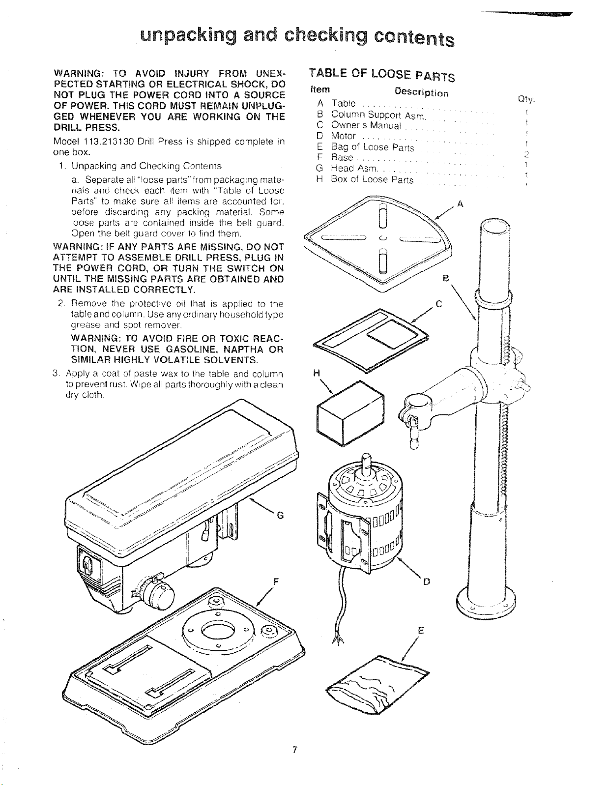
TABLE OF LOOSE PARTS
item Description
A Tab!e
B Column SUppori Asm.
c Owner s Manual .
D Motor .......
E Bag of Loose Parts
F Base ......
G Head Asm. ..
H Box of Loose Parts
H
\
2
i
!
F
/
E
B C
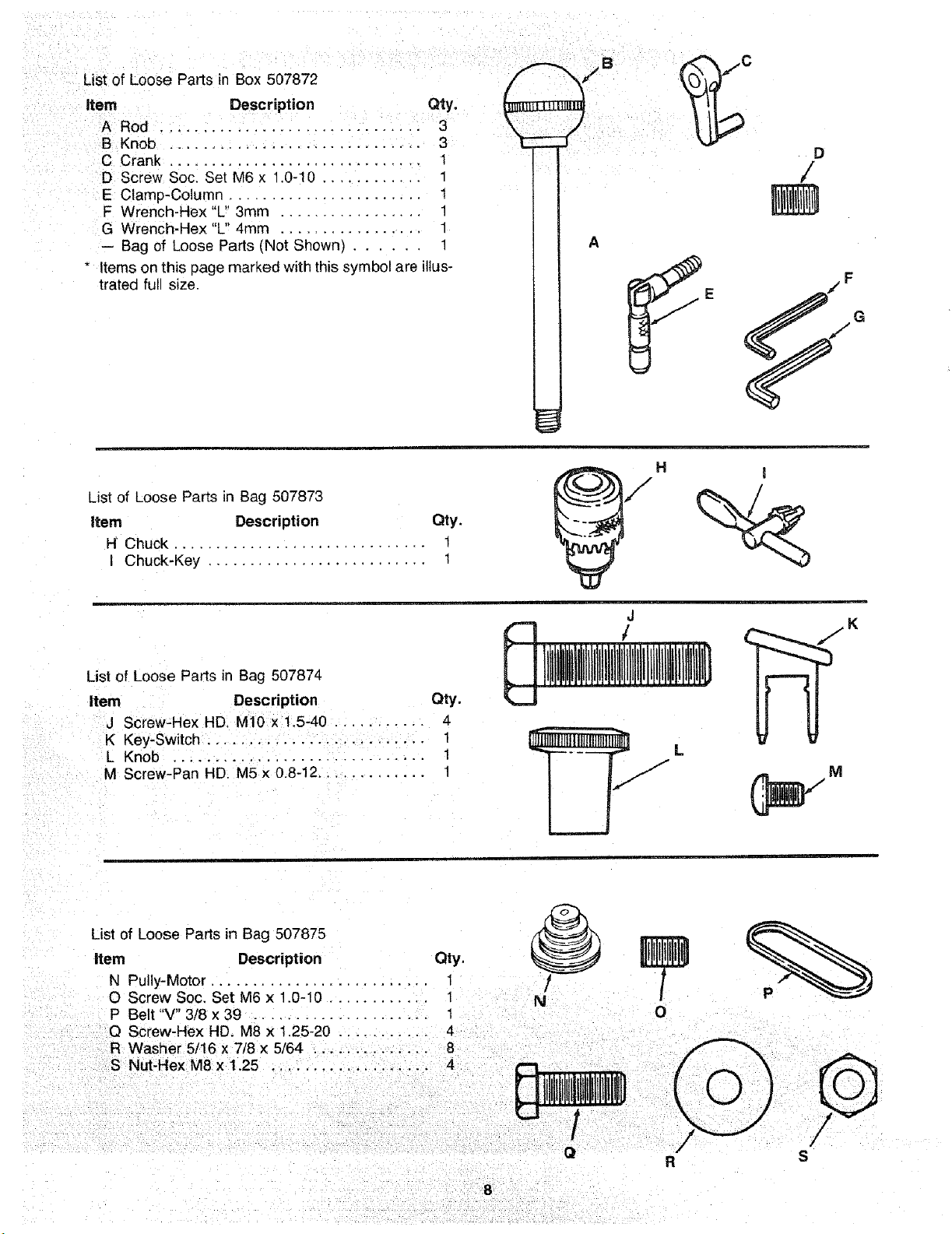
List of Loose Parts in Box 507872 /_'_/' _/
,tern Description Qty. _LU_ \ I1_'
Rod...................... 3 \ J I11
B Knob .................. 3 "_ --:f _ _
C Crank .............................. 1 /_
D Screw Soc. Set M6 x 1.0-10 ............ 1 /
E Clamp-Column,,. ...................... 1 _]_
F Wrench-Hex"L 3mm ................. 1
G Wrench-Hex "L" 4mm ................. 1
-- Bag of Loose Parts (Not Shown) ...... 1 A
* Items on this page marked with this symbol are illus-
trated full size. _E ._/F
H I
List of Loose Parts in Bag 507873
item Description Qty.
H Chuck ............................. t
Chuck-Key .......................... 1
List of Loose Parts in Bag 507874
Item Description Qty.
J Screw-Hex HD. M10 x !.5-40 ........... 4
K Key-Switch .......................... I
L Knob .............................. 1
M Screw-Pan HD. M5 x 0.8-12............. 1
List of Loose Parts in Bag 507875
Item Description Qty.
N Pully-Motor .......................... 1 /
O Screw Soc. Set M6 x 1.0-10 ............ 1
P Belt "V" 3/8 x 39 .................... 1
O Screw-Hex HD. M8 x 1.25-20 ........... 4
R Washer 5/16 x 7/8 × 5/64 .............. 8
S Nut-Hex M8 x 1.25 ................... 4
J
1
÷
0
l,l,Il!,BI,I,
8
/
O
/" /
R S
mecation and functien ef centrols
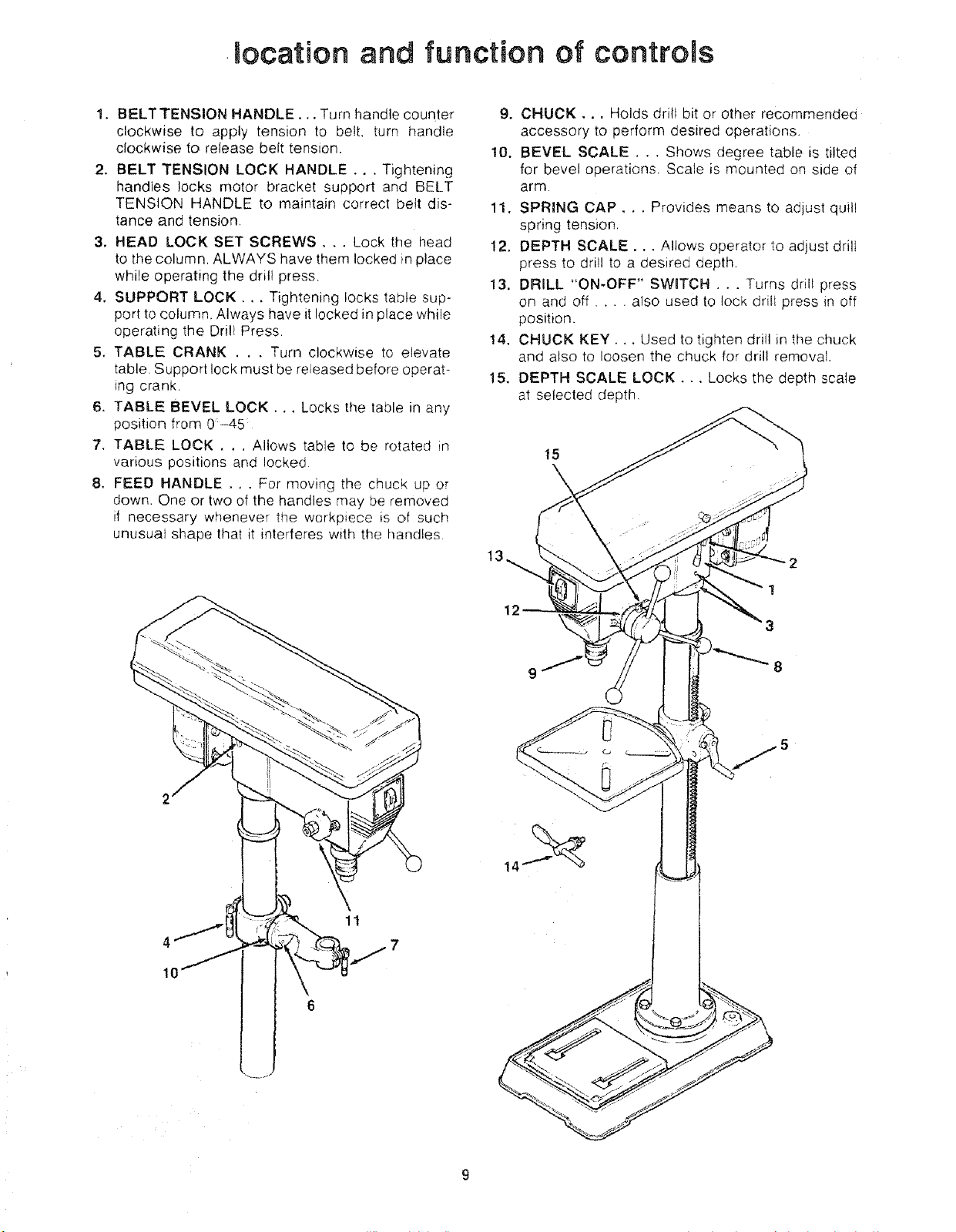
1. BELTTENSION HANDLE..• Turn handle counter
clockwise to apply tension to belt. turn handle
clockwise to release belt tension,
2. BELT TENSION LOCK HANDLE... Tightening
handles locks motor bracket support and BELT
TENSION HANDLE to maintain correct bett dis-
tance and tension
3. HEAD LOCK SET SCREWS... Lock the head
to the column, ALWAYS have them locked in place
while operating the drill press
4. SUPPORT LOCK •.. Tightening locks table sup-
port to column, Always have it locked in place while
operating the Drill Press
5. TABLE CRANK . , . Turn clockwise to elevate
table Support lock must be released before operat-
ing crank.
6. TABLE BEVEL LOCK.., Locks the table in any
position from 0-45
7. TABLE LOCK . . , Allows table to be rotated in
various positions and locked
8. FEED HANDLE . . . For moving the chuck up or
down One or two of the handles may be removed
if necessary whenever the workpiece is of such
unusual shape that it interferes with the handles
9. CHUCK.., Holds drill bit or other recommended
accessory to perform desired operations.
10. BEVEL SCALE, . . Shows degree table is tilted
for bevel operations. Scale is mounted on side of
arm
11. SPRING CAP, . . Provides means to adjust quill
spring tension,
12. DEPTH SCALE... Allows operator to adjust drill
press to drill to a desired depth.
13. DRILL "ON-OFF" SWBTCH . . . Turns drill press
on and off .... also used to lock drill press in off
position.
14, CHUCK KEY... Used to tighten drill in the chuck
and also to loosen the chuck for drill removal.
15. DEPTH SCALE LOCK.,. Locks the depth scale
at selected depth,
15
4
10
1
12
3
8
11
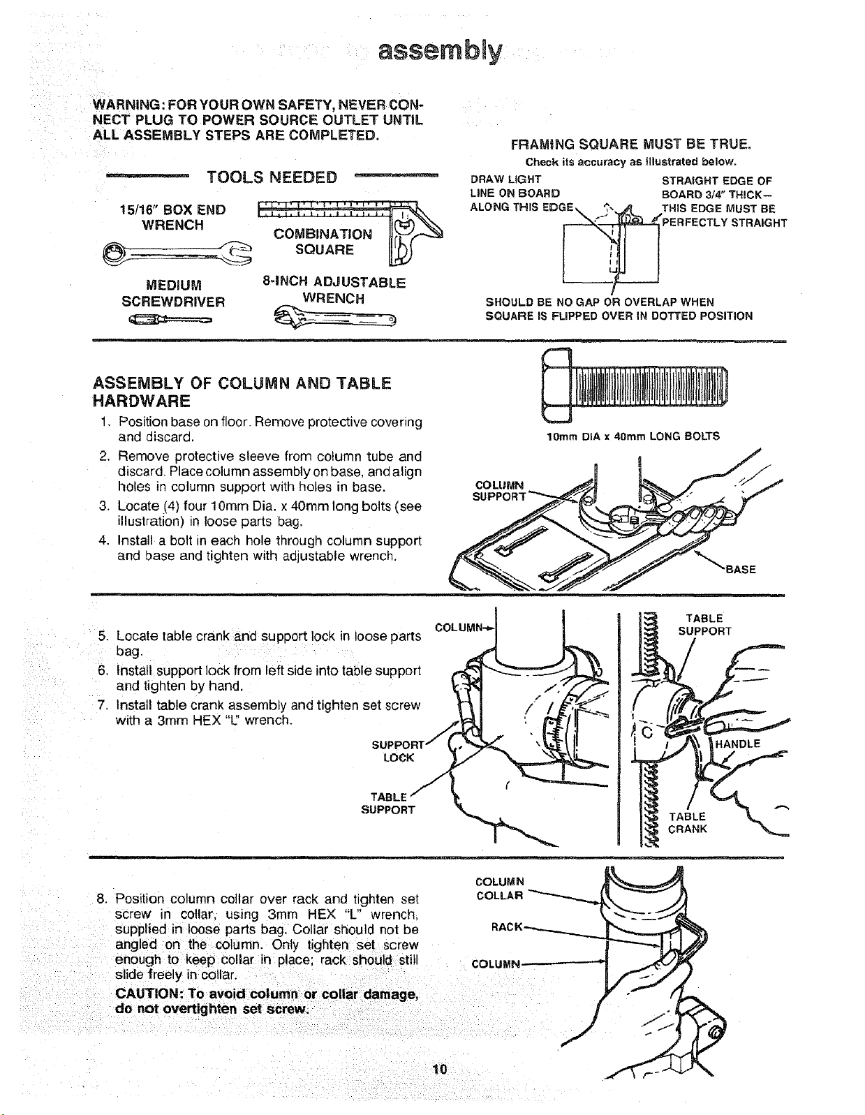
assembgy
WARNING :FOR YOUR OWN SAFETY, NEVER CON"
NECT PLUG TO POWER SOURCE OUTLET UNTIL
ALL ASSEMBLY STEPS ARE COMPLETED.
TOOLS NEEDED
15/16" BOX END
WRENCH
COMBINATION I[(_(.._
SQUARE [L_
FRAMING SQUARE MUST BE TRUE.
Check its accuracy as Illustrated belowo
DRAW LIGHT STRAIGHT EDGE OF
LiNE ON BOARD BOARD 3/4" THICK--
MEDIUM
SCREWDRIVER
8-INCH ADJUSTABLE
WRENCH
SHOULD BE NO GAP OR OVERLAP WHEN
SQUARE IS FLIPPED OVER iN DOTTED POSiTiON
ASSEMBLY OF COLUMN AND TABLE
HARDWARE
1, Positionbase on floor. Remove protective covering
and discard.
2. Remove protective sleeve from column tube and
discard. Place column assembly on base. one align
holes in column support with holes in base.
COLUMN
3. Locate (4) four 10turn Dia. x 40mrn long bolts (see
illustration) in loose parts bag.
4. Install a bolt in each hole through column support
and base and tighten with aojustable wrench.
m__
Locate table crank and support lock in loose arts COLLIMN"_I !
.
bag P J!P
6.
Install support lock from left side into tablesupport _ _ ._'-_'F__J._L
and tighten by hand _-."3_ ..-"/f
I ' '" " _'_
7.
nstal, table crank assembly and t,ghten set screw "_ 1 /" "/_
10mm DIA x 40ram LONG BOLTS
_'_BASE
TABLE
SUPPORT
witha 3mmHEX"L:'wrench. TJr_y (' _fr "-_'_,.._..,.._ \_L,.,qi'
COLUMN
8. Position column collar over rack and tignteP set COLLAR
screw in collar, using 3mm HEX "L" wrench.
supplied in loose parts bag, Collar should not be
angled on the column. Only tighten set screw
enough to keep collar in place: rack should still COLUMN
slide freely in collar.
CAUTION: To avoid column or collar damage,
do not overtlghten set screw.
10
HANDLE
TABLE
CRANK
 Loading...