

Craftsman 11320680 Owner’s Manual

owners
manual
MODEL NO.
113.20680
Serial
Number
Model and serial
number may be found
on a plate attached
to your infeed table.
You should record both
model and serial number
in a safe place for
future use.
CAUTION-.
Read GENERAL
and ADDITIONAL
SAFETY
INSTRUCTIONS
carefully
Sold by SEARS, ROEBUCK AND CO., Chicago, IL. 60684 U.SA.
Part No, 67018
6_- INCH JOIN TER-PLA NER
. assembly
o operating
e repair parts
CRRFTSMRNo

FULL ONE YEAR WARRANTY ON CRAFTSMAN JOINTER/PLANER
This warranty_giVesyou specific legal rights; and you may :alsohave other rights which varyfrom state to state.
SEARS. ROEBUCK AND CO.
BSC 41-3
SEARS TOWE R
CHICAGO, I L 60684
general safety instructions for power fools
KNOW YOUR POWE R TOOL
Read the owner's manual carefully, Learn its
application and limitations as well as the specific
potential hazards peculiar to this tool.
13. SECURE WORK
Use damps or a vise to hold work when practical. It's
safer than using your hand. frees both hands to operate
tool.
2. GROUND ALL TOOLS 14. DON'T OVERREACH
This tool is equipped with an approved 3-conductor Keep proper footing and balance at all times.
cord and a 3-prong grounding type plug to fit the
proper grounding type receptacle. The green conductor 15. MAINTAIN TOOLS WITH CAR E
in the cord is the grounding wire. Never connect the Keep tools sharp and clean for best and safest
green wire to a live terminal, performance. Follow instructions for lubricating and
3. KEEP GUARDS IN PLACE changing accessories.
in working order, and in proper adjustment and 16. DISCONNECT TOOLS
alignment, before servicing; when changing accessories such as
4. REMOVE ADJUSTING KEYS blades,bits, cutters, etc,
AND WRENCHES
Form habit of checking to see that keys and adjusting 17. AVOID ACCIDENTAL STARTING
wrenches are removed from toot before turning it on. Make sure switch is in "OFF" position before plugging
in.
5. KEEP WORK AREA CLEAN
Cluttered areas and benches invite accidents. Floor 18. USE RECOMMENDED ACCESSORIES
must not be slippery due to wax or sawdust, Consult the owner's manual for recommended
accessories. Follow the instructions that accompany
-6, AVOID DANGEROUS ENVIRONMENT the accessories. The use of improper accessories may
Don't use power tools in damp or wet locations or cause hazards,
expose them to _r_ain.: Keep, work area well lighted,
Provide adequate surrounding work space. _:: : z19_:NEVER STAND ON TOOL
7 k'l=l=P r_l-lllr_Rl=l_i _ " Serious in'ur cou d occur f the too ti if the
.................... •-,WAY : . ,. j y is pped or
All visitors should 5ekept a Safe ........ .
area, , Donor store materials above or near the tool .such that
cutting too s accidentally contacted
8. MAKE WORKSHOP KID-PROOF iris necessary to stand on the toot to reach them.
- with padlocks, master switches, or by removing
starter keys. 20. CHECK DAMAGED PARTS
9. DON'T FORCE TOOL Before further use of the tool, a guard or other part that
It will do the job better and safer at the rate for which is damaged should be carefully checked to ensure that it
it was designed, will operate properly and perform its intended function.
10. USE RIGHT TOOL Check for alignment of moving parts, binding of moving
Don't force tool or attachment to do a job it was not parts, breakage of parts, mounting, and any other
designed for, conditions that may ,affect its operation. A guard or
11. WEAR PROPER APPAREL other part that is damaged should be properly repaired
Do not wear loose clothing, gloves, neckties or jewelry
(rings, wrist watches) to get caught in moving parts;
Nonslip footwear is recommended. Wear protective 21. DIRECTION OF FEED
hair covering to contain long hair. Roll long sleeves : Feed work into a blade or cutter against the direction
above the elbow, of rotation of the blade or cutter only.
or replaced,
: 12, USE SAFETY GOGGLES (Head Protection)': • :
: Wear:Safety og es (must corn I w th ANSZ87 1)at : i 22. NEVER LEAVE TOOL RUNNING
:: ati times. A_so g Use::: face orP_tYust mask ill.cuffing: _: UNATTENDED
: operation is duSty_i andear protectors:(piugs,or muffS): : Turn power off. Don't eave tool until t comes to a
duringextended:_HodsiOf opel_atiort.=_:-: :: :: : complete stop.

additionaB safety instructions for iointer-paaner
Safety is a combination of operator common sense and
alertness at all times when the Jointer-Ptaner is being used.
WARNING: FOR YOUR OWN SAFETY, DO NOT AT-
TEMPT TO OPERATE YOUR JOINTER-PLANER UNTIL
IT IS COMPLETELY ASSEMBLED AND INSTALLED
ACCORDING TO THE INSTRUCTIONS,.. AND UNTIL
YOU HAVE READ AND UNDERSTOOD THE FOLLOW-
ING,
PAG E
t. GENERAL SAFETY INSTRUCTIONS FOR POWER
TOOLS .............................. 2
2. GETTING TO KNOW YOUR JOINTER-PLANER . . 12
3. BASIC MACHINE OPERATION .............. 19
4. USE OF HOLD-DOWN/PUSH BLOCKS ......... 20
5. MAINTENANCE ........................ 22
6. STABILITY OF MACHINE
If there is any tendency for the Jointer-Planer to tip
over or move during certain operations such as when
planing or jointing long heavy boards, the Jointer-
Planer (stand) should be bolted to the floor,
7. LOCATION
The Jointer-Planer should be positioned so neither the
operator nor a casual observer is forced to stand in line
with the wood while it is being planed.
This machine is intended for indoor use only. Provide
adequate lighting.
8. KICKBACKS
Kickbacks can cause serious injury. A kickback occurs
when the operator looses control of the workpiece
causing it to be kicked back toward him.
Kickbacks - and possible injury from them can usually be
avoided by:
a,
Holding the workpiece firmly against tables and fence.
b.
Not taking too deep a cut at one time. A deep cut
requires more effort to feed the wood while planing
and can cause the wood to kickback. A cut between
1/32 and 1/16 of an inch deep will produce the best
results.
C.
Not jointing, planing, or beveling pieces of wood
smaller than recommended. (See section in this man-
ual,'BasicJointer-Planer Operations.") Smaller pieces
of wood can tip over on the tables, or into the cutter
head and can be kicked back toward you.
9. PROTECTION: EYES, HANDS, FACE, EARS, BODY
a.
If any part of your jointer is malfunctioning, has been
damaged or broken.., such as the motor switch, or
other operating control, a safety device or the power
cord . . . cease operating immediately until the
particular part is properly repaired or replaced.
b.
Wear safety goggles that comply with ANSZ87. 1-
1968, and a face shield if operation is dusty. Wear
ear plugs or muffs during extended periods of opera-
tion.
C,
Do not plane, joint, or bevel wood shorter than t2
in. Smaller pieces of wood can tip over on the
tables, or into the cutterhead and be kicked back to-
ward you.
d_
Always use the hold down/push block when jointing
or beveling wood narrower than 3 in. but never joint
or bevel wood narrower than 3/4 in. under any cir-
cumstances.
e.
Always use the hold down/push blocks when planing
wood thinner than 3 in. but never plane wood thinner
than 1/2 in. under any circumstances.
f.
Avoid awkward hand positions, where a sudden slip
could cause a hand to move into the cutters.
g.
Never turn your Jointer-Planer "ON" before clearing
the table(s) of all objects (tools, scraps of wood, etc.)
except for the workpiece and related feed or support
devicesfor the operation planned.
h_
Make sure the cutterhead revolves in the right direc-
tion, (toward the infeed table).
KEEP CUTTER GUARD IN PLACE AND OPERAT-
ING PROPERLY AT ALL TIMES. Regularly check
the tension of the cutter guard spring to assure
satisfactory operation. (See Getting To Know Your
Jointer-Planer section,}
Always feed the wood completely through the cutter
head and past the cutter guard so that the guard re-
turns to the rest position against the fence. When
using only one hold down/push block to feed the
wood, do not place your other hand on the Jointer-
Planer.
10. Warped wood should be surface planed on the concave
sidefor best results.
11. To avoid a rough planed surface, determine if possible,
which way the grain emerges from the wood and feed
the wood accordingly.
d. Keeping blades sharp. BIades that are dull or nicked
require more effort While planing and will tend to
pound the wood rather than cut it, which can cause
the wood to kickback. A nicked blade will cut a rid-
ge in your wood and cause the wood to ride up on the
outfeed table, Make sure the cutter blades are in-
stalled properly, and cutter blade wedge screws are
tight.
_%"GRAIN EMERGtN/G
12. Do not plane edges of plywood, composition materials,
or wood that has glue on it or is painted or varnished.
Planing these materials will dull the blades quickiy.
3

additional safety instructions for a'ointer-pmaner ....
TO BECOME COMMONPLACE. ALWAYS REMEMBER
THAT A CARELESS FRACTION OF A SECOND IS
depth wanted, then raise the table to the desired depth_ SUFFICIENT TO INFLICT SEVERE INJURY.
14_:When planing, jointing, or beveling wood over:four (4)
feet Iongi make sure it is supported at table height.
15.: Never leave the Jointer-Planer work area with the power
on; before the Jointer-Planer has come to a complete
stop, or without removing and storing the switch key.
16, Never operate the Jointer-Planer with protective cover
on the unused shaft end of the motor removed.
WARNING: THE 2" JOINTER-PLANER PULLEY AND
THE 2-1/2"" MOTOR PULLEY FURNISHED WILL RUN
THE CUTTER HEAD AT APPROXIMATELY 4300 RPM
WHEN USED WITH A 3450 RPM MOTOR. NEVER
SUBSTITUTE OTHER PULLEYS TO INCREASE THIS
SPEED BECAUSE IT COULD BE DANGEROUS.
WARNING: DO NOT ALLOW FAMILIARITY (GAINED
FROM FREQUENT USE OF YOUR JOINTER-PLANER)
The operation of any power tool can result in foreign
objects being thrown into the eyes, which can result in
severe eye damage. Always wear safety goggles complying
with ANSI Z87.1 (shown on Package) before commencing
power tool operation. Safety Goggles are available at Sears
retail or catalog stores.
17: Read and followthe instructions appearing on the danger
label on the cutter guard.
DANGER
FOR YOUR OWN SAFETY
READ AND FOLLOW SAFETY INSTRUCTIONS IN
OWNERS MANUAL BEFORE OPERATING THIS MA-
CHINE.
NEVER OPERATE THIS MACHINE WITH THE CUT-
TER GUARD, SLIDING GUARD OR BELT GUARDS
REMOVED.
3.
NEVER MAKE J01NTING OR PLANING CUTS DEEP-
ER THAN 1/16 INCH,
4.
ALWAYS USE HOLD DOWN/PUSH BLOCKS FOR
JOINTING MATERIAL NARROWER THAN 3 iNCHES
OR PLANING MATERIAL THINNER THAN 3 INCHES.
cOntents
POWER TOOL GUARANTEE. ................... 2
GENERAL SAFETY INSTRUCTIONS FOR
POWER TOOLS .......................... 2
ADDITIONAL SAFETY INSTRUCTIONS FOR
JOINTER-PLANER ........................ 3
MOTOR SPECl FICATtONS AND ELECTRICAL
REQUIREMENTS ......................... 5
Connecting to Power Source Outlet ............ 5
Check Motor Rotation .................... 5
UNPACKING AND CHECKING CONTENTS ....... 6
ASSEMBLY ............................. 7
Mounting Jointer-Planer On Recommended
Craftsman Stand ........................ 7
Checking Cutterblade Screws ................ 7
Installing Sliding Guard .................... 8
Mounting Recommended Craftsman Motor and
Belt Guards ...........................
Check Motor Rotation. .................... 9
Jointer-Pulley Belt Guard Installation ........... 11
GETTING TO KNOW YOUR JOINTER-PLANER .... 12
Depth of Cut Handwheel .................. 12
Fence Locks and Stops .................... 13
Fence Tilt Scale ......................... 13
Cutterguard ............................ 15
Infeed Table ........................... 15
On-Off Switch .......................... 17
BASIC JOINTER-PLANER OPERATION ......... 19
Feeding the Workpiece .................... 19
Using the Hold Down/Push Blocks ............ 20
Beveling .............................. 21
MAINTENANCE .......................... 22
Replacing Cutter Blades.................... 22
Installing Cutter Guard Spring ............... 24
Sharpening Cutter Blades .................. 25
GENERAL MAINTENANCE .................. 26
WIRING DIAGRAM ........................ 26
8
LUBRICATION .......................... 26
TROUBLE SHOOTING ...................... 27
RECOMMENDED ACCESSORIES .............. 27
REPAIR PARTS ............. ............. 28
4
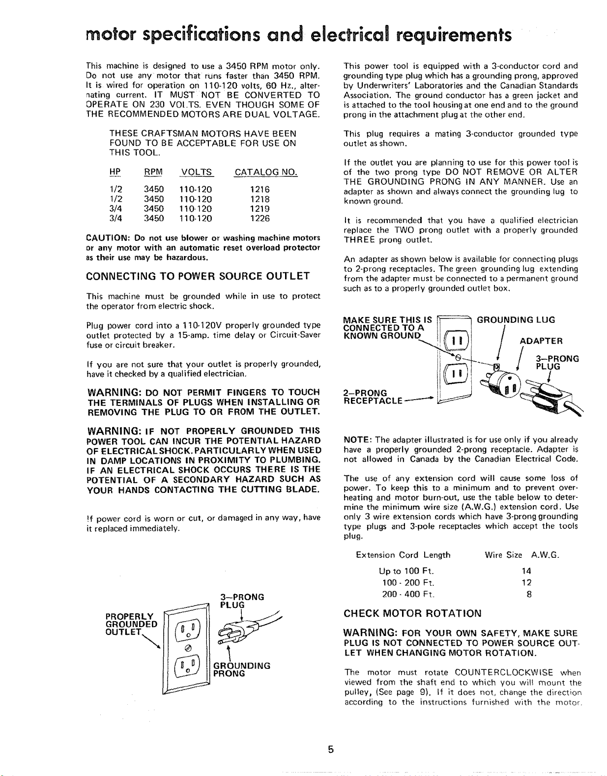
motor specifications and electrical requirements
]'his machine is designed to use a 3450 RPM motor only.
Do not use any motor that runs faster than 3450 RPM.
It is wired for operation on 1t0-120 volts, 60 Hz,, alter-
nating current. IT MUST NOT BE CONVERTED TO
OPERATE ON 230 VOI.TS. EVEN THOUGH SOME OF
]-HE RECOMMENDED MOTORS ARE DUAL VOLTAGE.
THESE CRAFTSMAN MOTORS HAVE BEEN
FOUND TO BE ACCEPTABLE FOR USE ON
THIS TOOL.
HP RP.___M VOLTS CATALOG NO.
1/2 3450 110-120 12t6
t/2 3450 110-120 1218
3/4 3450 1t0-120 1219
3/4 3450 t10-120 1226
CAUTION: Do not use blower or washing machine motors
or any motor with an automatic reset overload protector
as their use may be hazardous,
CONNECTING TO POWER SOURCE OUTLET
This machine must be grounded while in use to protect
the operator from electric shock.
Plug power cord into a 1 t0-120V properly grounded type
outlet protected by a 15-amp. time delay or Circuit-Saver
fuse or circuit breaker.
If you are not sure that your outlet is properly grounded,
have it checked by a qualified electrician,
This power tool is equipped with a 3-conductor cord and
grounding type plug which has a grounding prong, approved
by Underwriters' Laboratories and the Canadian Standards
Association. The ground conductor has a green jacket and
is attached to the tool housing at one end and to the ground
prong in the attachment piug at the other end.
This plug requires a mating 3-conductor grounded type
outlet as shown.
If the outlet you are planning to use for this power toot is
of the two prong type DO NOT REMOVE OR ALTER
THE GROUNDING PRONG tN ANY MANNER. Use an
adapter as shown and always connect the grounding tug to
known ground.
It is recommended that you have a qualified electrician
replace the TWO prong outlet with a properly grounded
THREE prong outlet.
An adapter as shown below is available for connecting plugs
to 2-prong receptacles. The green grounding lug extending
from the adapter must be connected to a permanent ground
such as to a properly grounded outlet box,
MAKE SURE THIS IS
CONNECTED TO A
KNOWN GROUND
GROUNDING LUG
ADAPTER
/ 3--PRONG
"-""-_.F._,/ PLUG
WARNING: DO NOT PERMIT FINGERS TO TOUCH
THE TERMINALS OF PLUGS WHEN INSTALLING OR
REMOVING THE PLUG TO OR FROM THE OUTLET.
WARNING: IF NOT PROPERLY GROUNDED THIS
POWER TOOL CAN INCUR THE POTENTIAL HAZARD
OF ELECTRICAL SHOCK, PARTICULARLY WHEN USED
IN DAMP LOCATIONS IN PROXIMITY TO PLUMBING.
IF AN ELECTRICAL SHOCK OCCURS THERE IS THE
POTENTIAL OF A SECONDARY HAZARD SUCH AS
YOUR HANDS CONTACTING THE CUTTING BLADE.
!f power cord is worn or cut, or damaged in any way, have
it replaced immediately.
3--PRONG
PLUG
PROPERLY
GROUNDED
OUTLET.
GROUNDING
PRONG
2-PRONG
RECEPTACLE ------'-_
NOTE: The adapter iltustrated is for use only if you already
have a properly grounded 2-prong receptacle. Adapter is
not allowed in Canada by the Canadian Electrical Code.
The use of any extension cord will cause some loss of
power. To keep this to a minimum and to prevent over-
heating and motor burn-out, use the table below to deter-
mine the minimum wire size (A.W.G.) extension cord. Use
only 3 wire extension cords which have 3-prong grounding
type plugs and 3-pole receptacles which accept the tools
plug.
Extension Cord Length Wire Size A.W.G.
Upto 100 Ft. !4
100- 200 Ft, 12
200- 400 Ft. 8
CHECK MOTOR ROTATION
WARNING: FOR YOUR OWN SAFETY, MAKE SURE
PLUG IS NOT CONNECTED TO POWER SOURCE OUT-
LET WHEN CHANGING MOTOR ROTATION.
The motor must rotate COUNTERCLOCKWISE when
viewed from the shaft end to which you wit_ mount the
pulley, (See page 9), if it does not, change the direction
according to the instructions furnished with the motor.
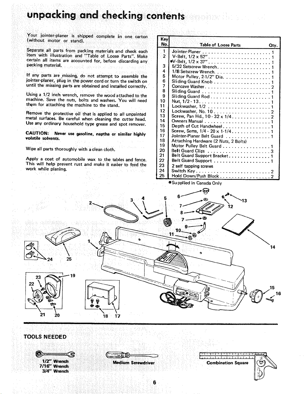
unpacking and heckmg contents:
Your: jointer:planer is ;shipped: complete in one carton
(_thou_: motor or Stand)_
Separateatl parts from packing materials and check each
item ;with illustration and "*Tabie: of Loose Parts'. Make
certain all items are accounted for, before discarding any
packing material.
If any parts are missing, do not attempt to assemble the
jointer-ptaner, plug in thepower cord or turn the switch on
until the missing parts are obtained and installed correctly.
Using a 1/2 inch wrench, remove the wood attached to the
machine. Save the nuts, bolts and washers. You will need
them for attaching the machine to the stand.
Remove the protective 0il that is applied to all unpainted
metal surfaces. Be careful when cleaning the cutter head.
Use any ordinary household type grease and spot remover.
CAUTION: Never use gasoline, na_ha or similar highly
volatile solvents.
Wipe all parts thoroughly with a clean cloth.
Apply a coat of automobile wax to the tables and fence.
This will help prevent rust and make it easier to feed the
work while planing.
C • i ¸ . • • • •• •
1 : Jointer-Planer ....................... 1
12 .i V:Belt, li2x 52". .................... !
IV-Belt, 1/2 x 37", .................... 1
3 5/32 Setscrew Wrench .................. 1
4 1/8 Setscrew Wrench ................... 1
5 Motor Pulley, 2-1/2"' Dia ................ 1
6 Sliding Guard Knob ................... 1
7 Concave Washer ...................... 2
8 Sliding Guard ....................... 1
9 Sliding Guard Rod .................... 1
10 Nut, 1/2- 13 ........................ 1
11 Lockwasher, 1/2 ..................... 1
12 Lockwasher, No. 10 ................... 2
13 Screw, Pan Hd., 10- 32 x !/4 ............. 2
14 Owners Manual ...................... 1
15 Depth of Cut Handwheel ................ 1
16 Screw, Sims, 1/4 - 20 x 1-1/4 ............. 1
17 Jointer-Ptaner Belt Guard ............... t
18 Attaching Hardware (2 Nuts, 2 Bolts)
19 Motor Pulley Belt Guard ................ 1
20 Belt Guard Clips ..................... 3
21 Belt Guard Support Bracket .............. 1
22 Belt Guard Support ................... 1
23 2 self tapping screws
24 Switch Key ......................... 2
t 25 Hold OownlPush Block .... • • ..._.. ..... 2
eSu pplied in Canada Only
Qty.
3 4
1,,.
19
21 20
II IIII IIII II II I I III , I, 11 HI IIIIIIIIIIII I I "'; '": ' , ......................................................
18 t7
5
14
16
•• : : ; ::•:•: : :/:i/: : i' %•
Square

assembly
MOUNTING JOINTER-PLANER ON RECOM-
MENDED CRAFTSMAN STAND
(NOT SUPPLIED IN CANADA)
See page 27 for recommended stand.
PARTS NEEDED
Nuts, Bolts and Washers removed when unpacking Jointer.
1 - Round Hd. Mach. Screw t/4-20 x 1-t/4 in. with Ext.
Tooth Lockwasher attached
1 - Depth of Cut Handwheel
TOOLS NEEDED
1/2 in. Wrench
Medium Screwdriver
1, Loosen FENCE LOCK KNOB.Tilt fence upward and slide
{t toward the pulley.
2, Place the machine on the stand as shown, and align
mounting holes.
FENCE LOCK
KNOB
1-1/4 IN. SCREW
It _.,2"/ _ _ FLAT WASHER
3. Place a fiat washer, a lock washer and a nut on each boff
from underneath the stand and tighten.
NOTE: The length of threads may vary on some bolts
and it may be necessary to add extra flat washers in order
to tighten the nuts securely,
4, Place handwheel on shaft aligning flat surfaces on shaft
with flat surfaces on handwheel,., attach with 1-1/4 in.
screw.
.....: ......................................... i,,, i i nl i i.,
CHECKING CUTTER BLADES AND SCREWS
TOOLS NEEDED
5/32" and 1/8" Setscrew Wrenches (furnished with
Jointer).
Lead Pencil
Short straight edge (or head of combination square)
1. Insert pencil in space at end of cutterhead to hold
cutterhead guard open.
2. Lower the infeed table with the Depth of Cut
HandwheeL
3. Rest the straight edge on edge on the surface of outfeed
table so it extends across the opening between the
tables, at three positions: near each end and at the
middle of the cutter blade.
4, Rotate the cutterhead by grasping the 2" dia. driven
pulley and make sure each knife ticks (touches) the
straight edge at all three positions, If not, follow
procedure under "REPLACING CUTTER BLADES" on
ppg. 22 & 23.
5/32 IN. SETSCREW
OUTFEED TABLE
WRENCH
WEDGE
PENCI L
CUTTER GUARD
5. If a cutter blade adjustment is not required, check each
locking screw of each wedge (5/32" setscrew wrench)
and tighten if necessary. Hold the pu{le¥ whiie
tightening screws and be careful that your fingers do not
slip off the wrench."
7

assembly
:= INSTALLING SLIDING GUARD
PARTS NEEDED
1; Sliding Guard
1: Sliding Guard Knob
1 Sliding Guard Rod
2 SlidingGuard Washers (one side of washer is concave)
1 Hex. Nut 1/2 in.- 13
1 Split Iockwasher 1/2 in.
2: EXt. tooth lockwashers
2 10-32x 1/4 Pan Hd. Screws
1. screw nut all the way onto long end of rod.., place
1/2 in. lockwasher next to nut.
2. Screw rod all the way into Jointer with short end up...
tighten nut.
3. Attach sliding guard to fence with two machine screws
and Iockwashers.
4. Place one Sliding Guard Washer, concave side DOWN on
support rod.
SLIDING GUARD ROD
SLIDING GUARD KNOB
10-32xl/4 SCREWS
EXT. TOOTH
LOCKWASH ERS
,: : i •:: i¸:•:I:
1/2 IN. HEX NUT
WASHER
(CONCAVE SIDE UP)
5. Drop sliding guard onto rod.., place other washer, con-
cave side UP on rod.., screw on Sliding Guard Knob.
MOUNTING RECOMMENDED CRAFTSMAN
MOTOR AND BELT GUARDS
See page 5 for recommended motors.
PARTS NEEDED
4 carriage bolts, 5/16 - 18 x 1 in., flat washers, lock washers
and nuts supplied with Craftsman Stand.
1 Jointer Planer Belt Guard
1 Motor Pulley Belt Guard
I Belt Guard Support
1 BeltGuard Support Bracket
3 Belt Guard Clips
1: Motor Pulleys,2-1/2 in; dia.
11 V-Bett:..
2 Pan Head S_rews 10 - 32 x 1/2 in. ......... '
2 Hex. Hd. Screws 1/4 -20x 1/2 in.
2 Hex. Nuts 1/4- 20
TOOLS NEEDED
Medium Screwdriver
5/32 in. Setscrew Wrench (furnished with Jointer)
1/2 and 7/16 in. Wrenches
8
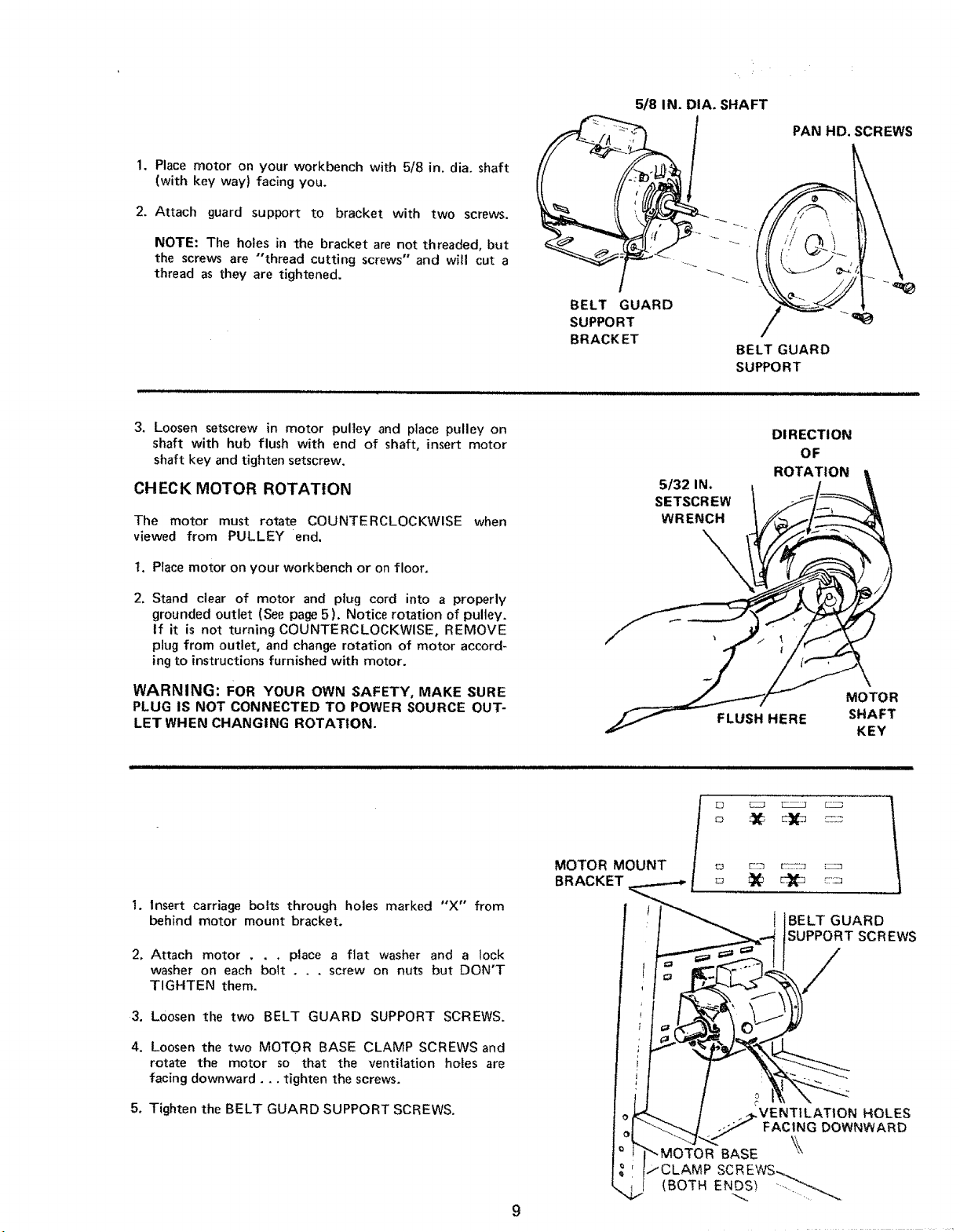
1. Place motor on your workbench with 5/8 in. dia. shaft
(with key way) facing you.
2. Attach guard support to bracket with two screws.
NOTE: The holes in the bracket are not threaded, but
the screws are "thread cutting screws" and will cut a
thread as they are tightened.
5/8 IN. DIA. SHAFT
BELT GUARD
SUPPORT
BRACK ET
PAN HID. SCREWS
BELT GUARD
SUPPORT
3, Loosen setscrew in motor pulley and place pulley on
shaft with hub flush with end of shaft, insert motor
shaft key and tighten setscrew.
CHECK MOTOR ROTATION
The motor must route COUNTERCLOCKWISE when
viewed from PULLEY end.
1. Place motor on your workbench or on floor,
2. Stand clear of motor and plug cord into a properly
grounded outlet (See page 5). Notice rotation of pulley.
If it is not turning COUNTERCLOCKWISE, REMOVE
plug from outlet, and change rotation of motor accord-
ing to instructions furnished with motor.
WARNING: FOR YOUR OWN SAFETY, MAKE SURE
PLUG IS NOT CONNECTED TO POWER SOURCE OUT-
LET WHEN CHANGING ROTATION.
1. Insert carriage bolts through holes marked "X" from
behind motor mount bracket.
2, Attach motor . . , place a flat washer and a lock
washer on each bolt . . . screw on nuts but DON'T
TIGHTEN them.
MOTOR MOUNT
BRACKET
5/32 IN,
SETSCREW
WRENCH
\,
DIRECTION
ROTATION
FLUSH HERE
BELT GUARD
OF
MOTOR
SHAFT
KEY
SCREWS
/
3. Loosen the two BELT GUARD SUPPORT SCREWS.
4. Loosen the two MOTOR BASE CLAMP SCREWS and
rotate the motor so that the ventilation holes are
facing downward.., tighten the screws.
5. Tighten the BELT GUARD SUPPORT SCREWS.
o
JCLAMP SCREWS
(BOTH ENOS_ _
.VENTILATION HOLES
FACING DOWNWARD
BASE
9

assembly
6.
Install three clips on belt guard 90° apart with long tabs
pointing AWAY from round opening.
7. Insert belt into open end of guard.
BELT
/
8. Snap guard into position as shown.
_'_"BELT GUARD CLIPS
(90° APART)
= .
10
 Loading...