

Craftsman 113201392 Owner’s Manual
Serial
Number ............
ModeJ and serial
number may be found
at the rear
of the cabinet.
You should record both
model and serial number
in a safe place for
future use.
CAUTION:
Read
SAFETY
iNSTRUCTIONS
carefully
CRRFTSMRHo
295 AMP
DUAL RANGE
ARC WELDER
® assembly
® operating
• repair parts
Sold by SEARS, ROEBUCK AND CO., Chicago, IL 60684 U,S.A.
Part No. 61341 _ :'_ ' . _ _,
SAFETY iNSTRUCTiONS TO OPERATOR
For your own protection, read and observe all instructions
mcluded nn this manual as well as the following specific
safety precautions.
1. PROTECTION FROM ELECTRICAL SHOCK
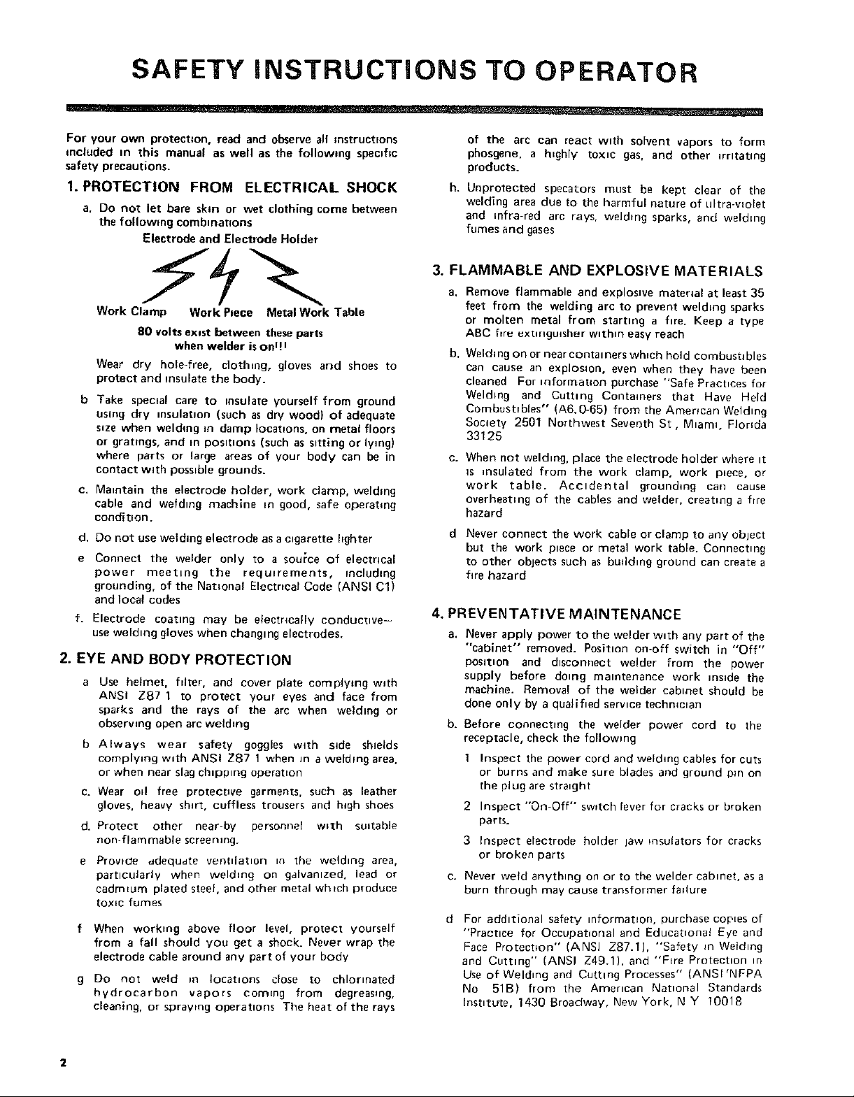
a. Do not let bare skin or wet clothing come between
the following combnnatlons
Electrode and Electrode Holder
Work Clamp Work Piece Metal Work Table
80 volts exast between these parts
when welder is onq I
Wear dry hole-free, clothing, gloves and shoes to
protect and insulate the body.
b Take special care to insulate yourself from ground
using dry =nsulatuon (such as dry wood} of adequate
s=ze when welding m damp Iocat,ons, on metal floors
or gratings, and in positions (such as s_tting or lying)
where parts or large areas of your body can be in
contact w_th possible grounds.
c. Manntain the electrode holder, work clamp, welding
cable and welding machine in good, safe operating
condition.
d. Do not use welding electrode as a cigarette hghter
e Connect the welder only to a source of electrical
power meeting the requ,rements, including
grounding, of the National Electrical Code (ANSI C1)
and local codes
f. Electrode coating may be eleetncaUy conductnve-
use welding gloves when ehangnng electrodes.
2. EYE AND BODY PROTECTION
a Use helmet, filter, and cover plate complytng with
ANSI Z87 1 to protect your eyes and face from
sparks and the rays of the arc when welding or
obserwng open arc weld=rig
b Always wear safety goggles with side shields
complying with ANSI Z87 1 when Jn a welding area,
or when near slag chipping operation
c. Wear od free protective garments, such as leather
gloves, heavy shirt, cuffless trousers and high shoes
d. Protect other near-by personnel w_th suitable
non flammable screening.
e Provide ddequdte ventilation in the welding area,
particularly when welding on galvanized, lead or
cadmeum plated steel, and other metal whtch produce
toxic fumes
f When worktng above floor level, protect yourself
from a fall should you get a shock. Never wrap the
electrode cable around any part of your body
g Do not weld m Iocat=ons close to chlorinated
hydrocarbon vapors com=ng from degreasmg.
cleaning, or sprawng operations The heat of the rays
of the arc can react with solvent vapors to form
phosgene, a highly toxic gas, and other irritating
products.
h. Unprotected specators must be kept clear of the
welding area doe to the harmful nature of ultra-wolet
and infra-red arc rays, welding sparks, and welding
fumes and gases
3. FLAMMABLE AND EXPLOSIVE MATERIALS
a. Remove flammable and explosive mater_al at least 35
feet from the welding arc to prevent welding sparks
or molten metal from starting a fire. Keep a type
ABC f_r_ extinguisher within easy reach
b,
Welding on or near containers wh,ch hold combustibles
can cause an expiosmn, even when they have been
cleaned For =nforn_atcon purchase "Safe Practtces for
Welding and Cutting Containers that Have Held
Combustrbles" (A6.0-65} from the Amerfcan Welding
Society 2501 Northwest Seventh St, Mnam_ FJorlda
33125
C.
When not welding, place the electrode holder where it
is _nsulated from the work clamp, work p=ece, or
work table. Accidental grounding can cause
overheating of the cables and wetder, creating a fire
hazard
d
Never connect the work cable or clamp to any object
but the work piece or metal work table. Connectnng
to other objects such as budding ground can create a
fire hazard
4. PREVENTATIVE MAINTENANCE
a,
Never apply power to the welder wnth any part of the
"cabinet" removed. Position on-off switch in "Off"
posltnon and disconnect welder from the power
supply before donng maintenance work inside the
machine. Removal of the welder cabinet should be
done only by a qualifned servnce techmcran
b. Before connecting the welder power cord to the
receptacle, check the following
1 Inspect the power cord and welding cables for cuts
or burns and make sure blades and ground pm on
the plug are stranght
2 Inspect "On-Off" sw_tch fever for cracks or broken
parts.
3 Inspect electrode holder law insulators for cracks
or broken parts
e. Never weld anything on or to the welder cabinet, as a
burn through may cause transformer failure
d
For additional safety information, purchase copies of
"Practice for Occupational and Educational Eye and
Face Protection" (ANSI Z87.1), "Safety _n Welding
and Cutting" (ANSI Z49.1), and "F_re Protection in
Use of Welding and Cutting Processes" (ANSI'NFPA
No 51B) from the Amerncan Natnonal Standards
[nstntute, 1430 Broadway, New York, N Y 10018
2
READ AND OBSERVE THE INSTRUCTIONS
APPEARING ON THE WARNING LABELS FOUND ON
THE INSIDE OF THE WELDING HELMET, SELECTOR
PLATE, AND CABINET,
_ARNIrJG Pro_e_t _ou,_lf and _ther_ R_d and
_U',IES _rJD GASE_ _arl be _l_r,ge,v_s to _,l_r ne_h_
_pC RA' g _an 1nitre eves _nd bdrr, ,kin _LECTRIC
SHOCK, n r,ll
• _ead _rd understand the m=m_fJ_l_r_, ,n,tr_¢tlons
• Feep y_ur he_d our _t th_ f_,,_es
• U,e en_o@h vent,lab,on eqhust _ tb_ _rc o_ _oth
• Wea_ correct eye eor _ml uauy protect,on
• See Am=r,_n p_uonal Sl_n_rJ Z49 I S_fel_ ,n
un_,stalld thl_ Idbel
•n_ y_ur enlp_owr • _fet, praCtl_eS
ro keep fu,_e_ and qase, rr_nl y_r ble_th,ng _one
and th_ _ner_l are_
¢,eld, l_ _,1_ (urr,,_g m,_h,hall b, the ,_er,c_n
'_eld,nc Society 2501 _ 71h St "1_,_, FL_r,da
_3125 OSH& S,r_t_ a,lo H_lhh _ta_cla,_, ?gCFR
_910 _,l_b_e Tr_rn U _ D_pJrtn,e_l_ _f L_bar
,_asn,_l_n DC 2O210
O0 NOT _E_O. E THIS L_BEL
_AFTSMRn
12_ 0_fy for €_c1__ _ Pr_ecb0n
a_,_hr_l _nlU_o_ rays from _C _dhng
_,hPn _m_ lil_S _v_ce _mpacl re
3rid serI_L_SI_ reduce pt01_CllOn--
Inspe_l rr_quenll 7 ,_nd _mm_al_l_
_NOT REMOVE THiS L_L
LENS @
SHADENO
WARNING -- FOR YOUR SAFETY
REGARD;NG 80 VOLT pO'_ENTIAL
_HOCK AT ELECTRODE
R£GARDING POTENTIAL SHOCK 0_ CABI¢_ET
• , _ u _ _ , _ ,. _ _ _
REGARDI_IG EYE _NJU_y
FIEGARDFNG F_ItE
WARNING" ARC WELDING CAN BE INJURIOUS TO OPERATOR AND PERSONS IN WORK AREA -
READ AND UNDERSTAND OWNERS MANUAL BEFORE OPERATING WELDER
FULL ONE YEAR WARRANTY ON CRAFTSMAN ELECTRIC WELDER
If this Craftsman Electrm Welder fails to perform properly, due to a defect in material or workmanship,
within one year from the date of purchase, Sears wdl repair It, free of charge
Warranty service is available by simply returning the welder to the nearest Sears store or Serwce Center
throughout the United States.
Th_s warranty gives you specific legal rights, and you may also have other rights which vary from state to
state.
SEARS, ROEBUCK AND CO
BSC 41-3
SEARS TOWER
CHICAGO. IL 60684
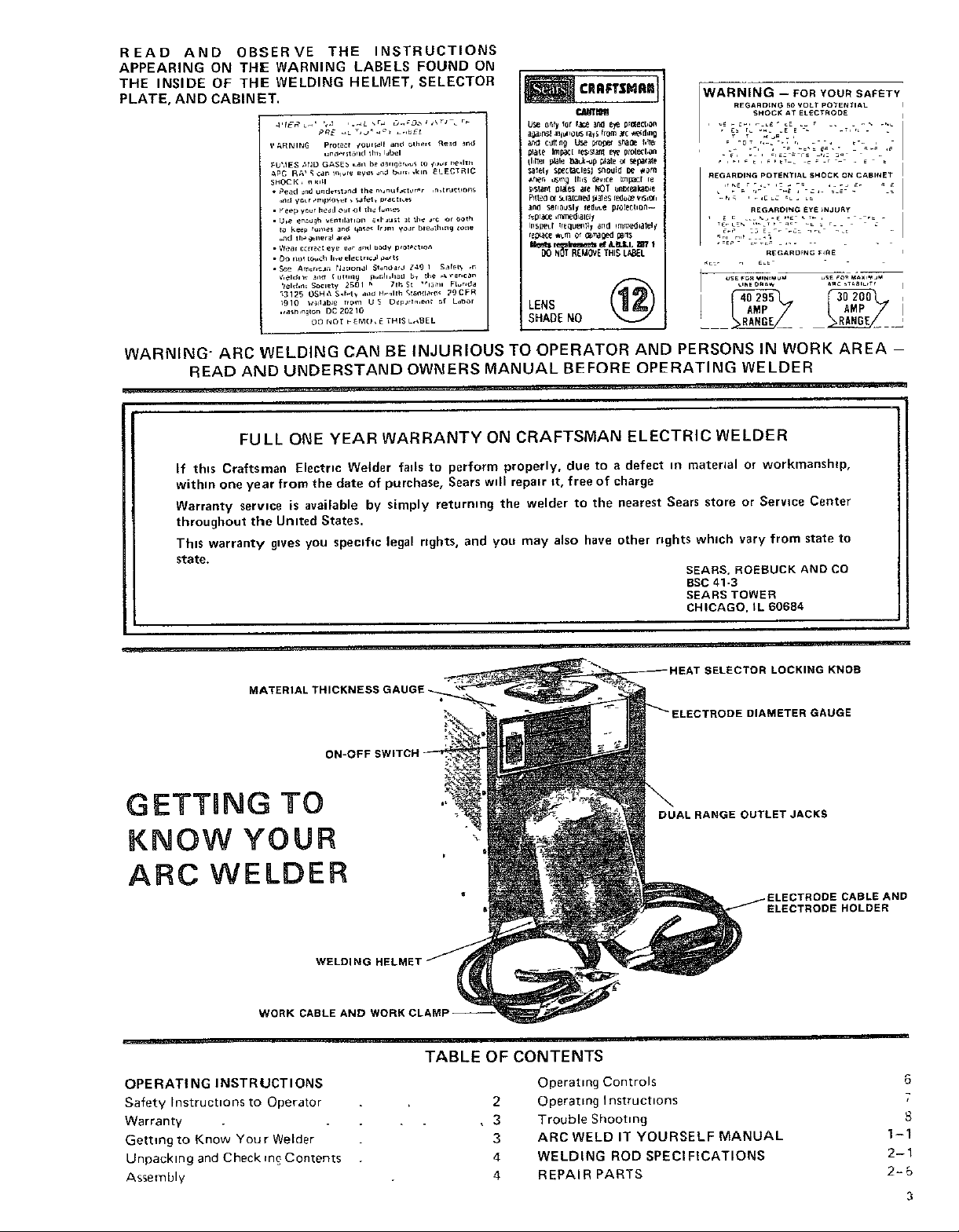
MATERIAL
GETTING TO
KNOW YOUR
ARC WELDER
WORK CABLE AND
OPERATING INSTRUCTIONS
Safety Instructions to Operator
Warranty
Getting to Know Your Welder
Unpacking and Check m_ Contents
Assembly
WELDING
TABLE OFCONTENTS
Operating Controls
2
Operating Instructions
• 3
Trouble Shooting
ARC WELD IT YOURSELF MANUAL
3
4
WELDING ROD SPECIFICATIONS
4
REPAIR PARTS
;ELECTOR LOCKING KNOB
LECTRODE DIAMETER GAUGE
DUAL RANGE OUTLET JACKS
:TRODE CABLE AND
ELECTRODE HOLDER
6
7
1-1
2-1
2=5
3
SPECIFICATIONS
Welding Range .............. 30 - 295 amps Hertz .............................. 60
Primary Volts (AC) ........ 230 Open C=rcult Volts (Max.) ................. 80
Amps Input (Max.) ................... 60 Duty Cycle ..................... 20% to 100%
Fuse Requ=red (Delayed Act=on Type) ......... 60 Etectrode Capacity .......... 1/16" thre 1/4"
Phase ....................... Single Over-all Dimensions .......... 21" x 14'" x 15"
UNPACKING AND CHECKING CONTENTS
SET-UP INSTR UCTIONS
Th_s Craftsman welder =s sh_pped complete _n one carton
In order to facd=tate packaging, certain =terns have been
removed at the factory and must be assembled when
received by the purchaser Remove all =terns from the
carton and =dent=fy =tern as shown m the exploded view
If'_l
,,,4:,:
1 2
WELDER _'_""'_ 4 5
_llustratton These "Loose Parts" should be accounted for
before discarding any packaging matertal
LOOSE PARTS LIST
Key
No. PartName Qty.
1
Welding Helmet (Partraflyassembled) .....
2
Helmetbandassembly{NotAssembled) . .
3
Electrodecableassembly .......
4
OwnersManual ..............
5
LoosePartsBag- Containingthefollowmg ttems
ElectrodeHolder .....
1/4" Hex"'L" Wrench .........
Work Clamp . ....
ElectrtaalOutletBox
Screw.Pan Hd Ty "AB" N'O"10x'1"/2 " ""
Outlet Box Cover ......
GroundTerminal
Screw,PanHd 10-32 x 1/2 ....
Lockwasher,No. 10 ....... :
Nut, Hex 10-32 ....
Connection Label .....
1
1
1
1
]
1
!
1
2
!
1
1
1
1
1
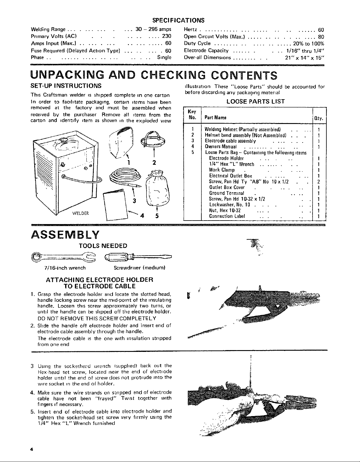
ASSEMBLY
TOOLS NEEDED
7/16-inch wrench Screwdriver (medluml
ATTACHING ELECTRODE HOLDER
TO ELECTRODE CABLE
1. Grasp the electrode holder and locate the slotted head,
handle locking screw near the rind-point of the insulating
handle. Loosen th_s screw approximately two terns, or
until the handle can be shpped off the electrode holder.
DO NOT REMOVE THIS SCREW COMPLETELY
2. Sbde the handle off electrode holder and insert end of
electrode cable assembly through the handle.
The electrode cable =s the one with insulation stopped
from one end
3 Using the socke[he_d wrench Isupphedl back oet the
Hex head set screw, Ioca[ed near the end of electlode
holder untd the end of screw does not protrude into the
wire socket m the end of holder.
4. Make sure the wire strands on stopped end of electrode
cable have not been "frayed" Twist together with
fingers _f necessary.
5. Insert end of electrode cable into electrode holder and
tighten the socket-head set screw very hrmly usmg the
1/4" Hex "L'" Wrench furnished
_r
4
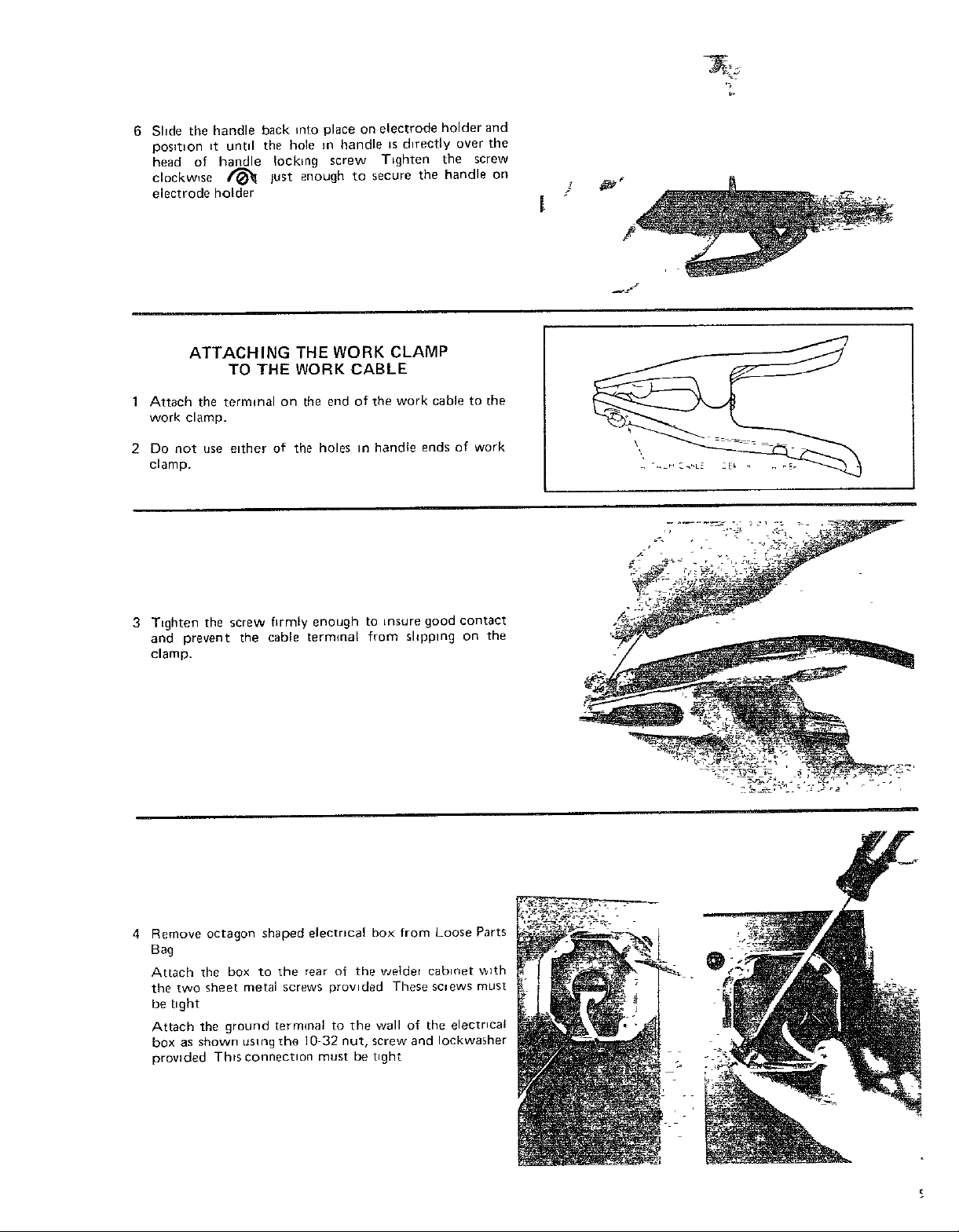
6 Slide the handle back into place on electrode holder and
pos_t_on tt untd the hole m handle _s d_rectly over the
head of handle locking screw TLghten the screw
clockwise _ lust enough to secure the handle on
electrode holder
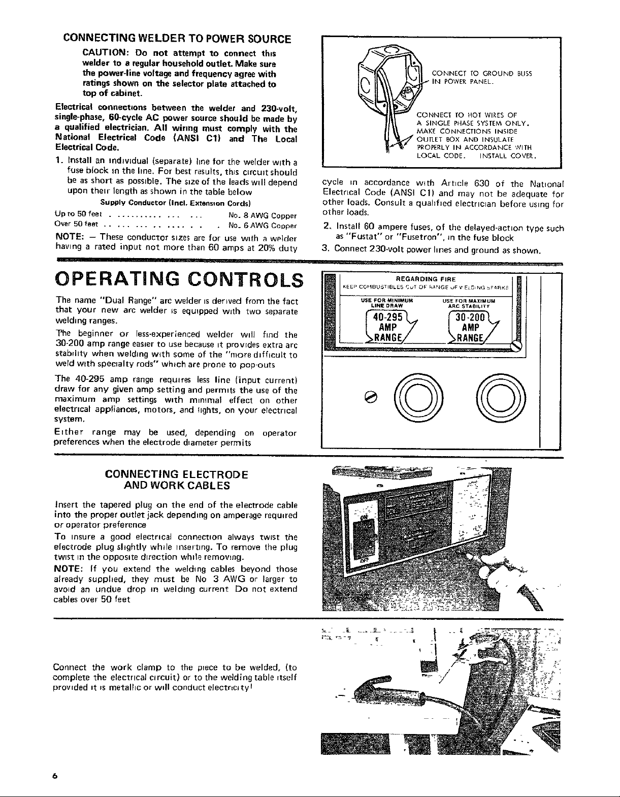
ATTACHING THE WORK CLAMP
TO THE WORK CABLE
1 Attach the terminal on the end of the work cable to the
work clamp•
2 Do not use e_ther of the holes m handle ends of work
clamp.
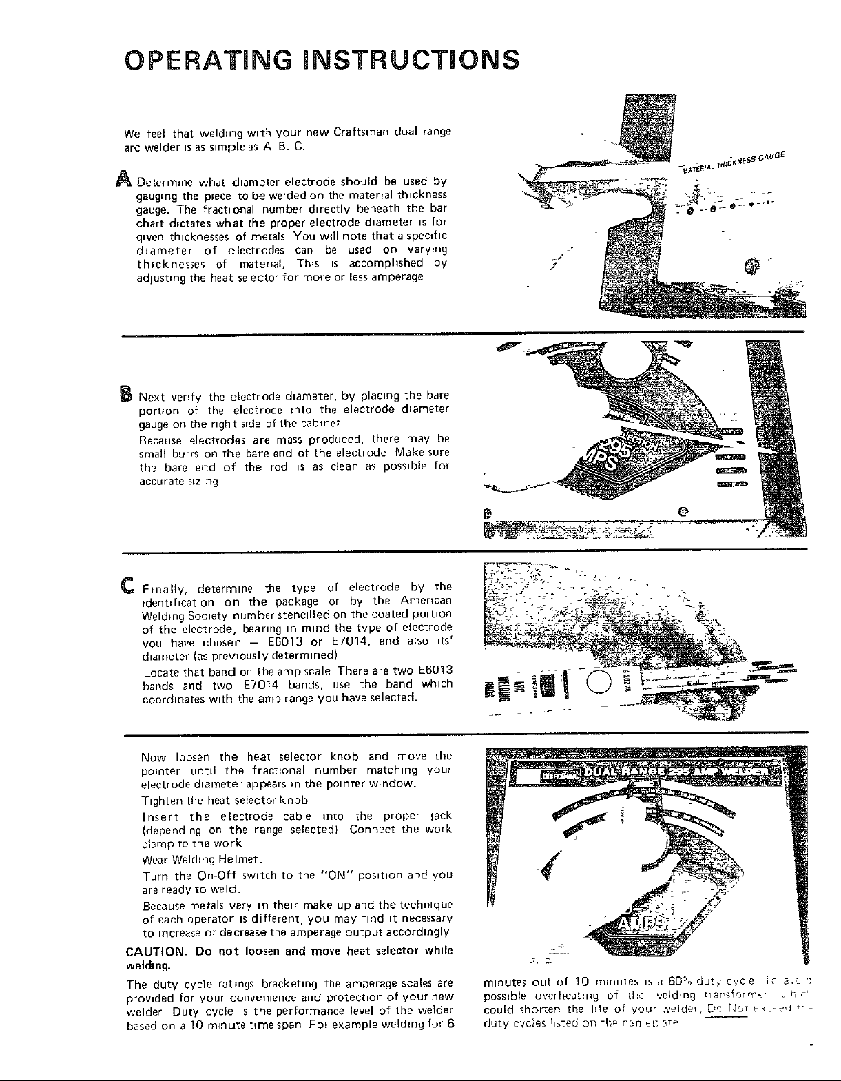
3 T_ghten the screw hrmly enough to insure good contact
and prevent the cable terminal from shppmg on the
clamp.
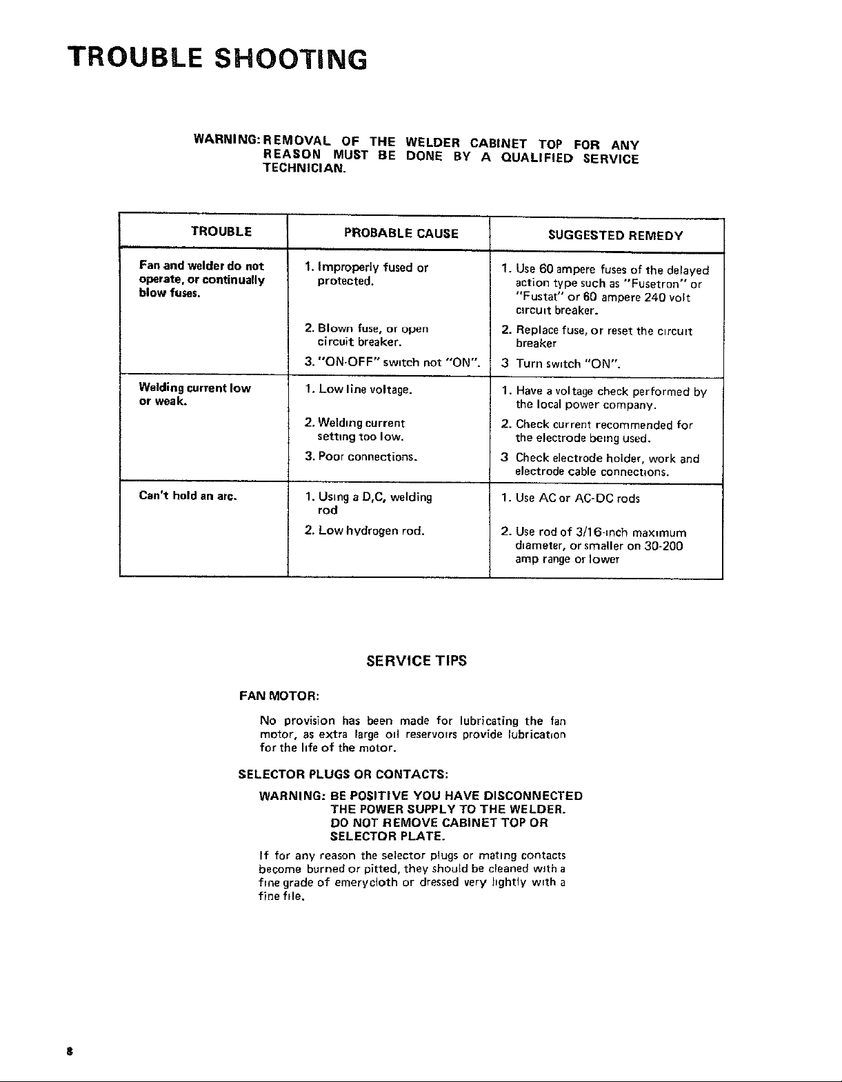
4 Remove octagon shaped electrical box from Loose Parts
Bag
Attach _he box to the rear of the we_det cabinet _th
the two sheet metal screws provided These screws must
be bght
Attach the ground terminal to the wall of the electrical
box as shown using zhe 10-32 nut, screw and Iockwasher
provided This connection must be t_ght
• %
CONNECTING WELDER TO POWER SOURCE
CAUTION: 0o not attempt to connect this
welder to a regular household outlet. Make sure
the power-line voltage and frequency agree with
ratings shown on the selector plate attached to
top of cabinet.
Electrical connections between the welder and 230-volt,
single-phase, 60-cycle AC power source should be made by
a qualified electrician, A_| wiring must comply with the
National Electrical Code (ANSI C1) and The Local
Electrical Code,
1. install an individual (separate) line for the we[der with a
fuse block m the hne. For best results, this circuit should
be as short as possible. The size of the leads will depend
upon their length as shown in the table below
Supply Conductor (incl. Extension Cords)
Up to 50 feet ................. No. 8 AWG Copper
Over 50 feet ................. No. 6 AWG Copper
NOTE: -- These conductor sizes are for use with _ wP]der
having a rated input not more than 60 amps at 20% duty
OPERATING CONTROLS
The name "Dual Range" arc welder tsderwed from the fact
that your new arc welder =s equtpped with two separate
welding ranges.
?he be_jinner or less-experienced welder will f_nd the
30-200 amp range easier to use because it provides extra arc
stabdlty when welding with some of the "more d_fhcult to
weld with specralty rods" which are prone to pop-outs
The 40-295 amp range requires less line (input current)
draw for any given amp setting and permits the use of the
maximum amp settings w=th minimal effect on other
electncal appliances, motors, and hghts, on your electrtcal
system.
Either range may be used, depending on operator
preferences when the electrode diameter permits
IN POWER £ANEL.
CONNECT TO HOT WIRES OF
A SINGLE PHASE SYSTEM, ONLY,
CONNECT rO GROUND BURS
MAKE CONNECTIONS INSIDE
OUTLET BOX AND INSULATE
pERkY IN ACCORDANCE '/ITH
LOCAL CODE. INSTALL COVER,
cycle in accordance with Article 630 of the Nat_ona{
Electrical Code (ANSi CI) and may not be adequate for
other loads. Consult a quahfled electrician before us=ng for
other loads.
2, install 60 ampere fuses, of the delayed-action type such
as "Fustat'" or "Fusetron", m the fuse block
3. Connect 230-volt power hnes and ground as shown.
iii, ...............
KEEP C_tBU_TIBLES _JT OF RA_JGE _F V ELDI_G _FC_K_
USE FOR MINIMUM US_ FOR MAXIMUM
REGARDING FIRE
CONNECTING ELECTRODE
AND WORK CABLES
Insert the tapered plug on the end of the electrode cable
into the proper outlet jack depending on amperage required
or operato_ preference
To Insure a good electrical connectFon always twist the
electrode plug slightly whde inserting. To remove the plug
twist in the opposite direction whde removing.
NOTE: If you extend the welding cables beyond those
already supphed, they must be No 3 AWG or larger to
avoid an undue drop in welding current Do not extend
cables over 50 feet
Connect the work clamp to the mece to be welded, (to
complete the electrical circuit) or to the welding table rtself
provided it rs metalhc or wdl conduct electncl ty r
%
OPERATING iNSTRUCTiONS
We feel that weldtng wtth your new Craftsman dual range
arc welder isas s_mple as A B. C.
A Determine what diameter electrode should be used by
gauging the piece to be welded on the material thickness
gauge. The fractional number d_rectly beneath the bar
chart d_ctates what the proper electrode d_ameter is for
g_ven thicknesses of metals You wgl note that a specific
diameter of electrodes can be used on varying
thicknesses of mater_al, Th_s _s accomphshed by
adlustmg the heat selector for more or less amperage
B Next verdy the electrode diameter, by placing the bare
porbon of the electrode into the electrode d_ameter
gauge on the right s_de of the cabinet
Because electrodes are mass produced, there may be
smag burrs on the bare end of the electrode Make sure
the bare end of the rod _s as clean as possible for
accurate sizing
/
C Finally, determine the type of electrode by the
tdent_ficatlon on the package or by the American
Welding Soctety number stenctlled on the coated portion
of the electrode, bearing in m_nd the type of electrode
you have chosen - E6013 or E7014, and also _ts'
diameter (as prewously determtned)
Locate that band on the amp scale There are two E6013
bands and two E7014 bands, use the band which
coordinates w_th the amp range you have selected.
Now loosen the heat selector knob and move [he
pointer untd the fractional number matching your
electrode diameter appears m the pointer window.
Tighten the heat seEector knob
Insert the electrode cable mto the proper tack
(dependmg on the range selected) Connect the work
clamp to the work
Wear Welding Helmet.
Turn the On-Off swttch to the "ON" positron and you
are ready to weld.
Because metals vary m their make up and the techntque
of each operator [s different, you may find _t necessary
to increase or decrease the amperage output accordingly
CAUTION. Do not loosen and move heat selector whde
welding.
The duty cycle ratings bracketing the amperage scales are
provided for your convenience and protection of your new
welder Duty cycle is the performance level of the welder
based on a 10 m4nutehrnespan Fo_ example wetdlng for 6
minutes out of 10 minutes _s a 60% dut,, c,,,ele Tc a,c !
possible overheatlr_g of _he _e_dlng tTal,s{o_q_',_ ' _ h _'
could shorten the hfe of your ,velde_, Dc [.Jo7 v<.-._,J tr
duty c,/c_es t_ied ON "h_ r-213 _D'3_ _"
TROUBLE SHOOTING
WARNING:REMOVAL OF THE WELDER CABINET TOP FOR ANY
REASON MUST BE DONE BY A QUALIFIED SERVICE
TECHNICIAN.
TROUBLE PROBABLE CAUSE SUGGESTED REMEDY
Fan and welder do not
operate, or continually
blow fuses.
Welding current low
or weak.
Can't hold an arc.
1. Improperly fused or
protected.
2. Blown fuse, or opeR
circuit breaker.
3. "ON-OFF" sw=tch not "ON".
1. Low line voltage.
2. Welding current
setting too low.
3. Poor connections.
1. Using a D,C, welding
rod
2. Low hydrogen rod.
SERVICE TIPS
1.
Use 60 ampere fuses of the delayed
action type such as "'Fusetron" or
"'Fustat" or 60 ampere 240 volt
mrcutt breaker.
2.
Replace fuse, or reset the ctrcu_t
breaker
3
Turn switch "ON".
1. Have a voltage check performed by
the local power company.
2. Check current recommended for
the electrode being used.
3 Check electrode holder, work and
electrode cable connections.
1. Use ACor AC-DC rods
2. Use rod of 3!16-inch maximum
d=ameter, or smaller on 30-200
amp range or lower
FAN MOTOR:
No provision has been made for lubricating the fan
motor, as extra large otl reservoirs provide lubrication
for the hfe of the motor.
SELECTOR PLUGS OR CONTACTS:
WARNING: BE POSITIVE YOU HAVE DISCONNECTED
THE POWER SUPPLY TO THE WELDER.
DO NOT REMOVE CABINET TOP OR
SELECTOR PLATE.
If for any reason the selector plugs or mating contacts
become burned or pitted, they should be cleaned with a
fine grade of emerycloth or dressed very bghtly w=th a
fine file.
8
t:RRFTSMRNo
A COMPREHENSIVE
GUIDE FOR YOUR
NEW CRAFTSMAN
ARC WELDER AND
WHAT iT WiLL DO
CONTAINS:
INFORMATION ABOUT
• VARIOUS TYPESOF RODS
• USEFUL ACCESSORIES
• TIPS ON CUTTING° WELDING
AND BRAZING
J
Form No. SP574-4 _'_
r.._o_.;__ _,_ __ ,_j_ ___,_ ,L_ .
TABLE OF CONTENTS
Your Welder and What It Will no ............. 1-3
How the Craftsmen Contact Rod Simplifies Welding 1-3
Wkat Happens When You Weld? .............. 1-3
Read Before Welding ...................... 14
Learn By Doing .......................... 1-5
Position Welding ......................... t-t 1
Cest-lron Welding ........................ 1.14
Hsrd Surfacing Worn Cutting Edges .......... 1-15
The Twin Carbon Arc Torch .............. 1-16
Cutting and Other Milcellaneo=JsOperations , .. !-17
Inert-Gas Metal*Arc Welding ................ 1-19
Page
Read this Manual carefully for additional welding information.
1-2
SEARS, ROEBUCK AND COMPANY
AND SIMPSONS-SEARS LIMITED
YOUR WELDER and what it will do..,
Your CRAFTSMANArc Welderisasturdilyconstructedandthoroughlytestedmachineengineeredto
give many years of efficient trouble-free service.It is listed by Underwriters' Laboratories,
incorporated,which meansthat it passesall requirementsof safety, fire hazardandtemperaturerise
limitsasspecifiedintheir Standardfor Transfer-TypeArc-WeldingEquipment.
HOWTHE CRAFTSMAN ELECTRODE
SIMPLIFIES WELDING
Craftsman Contact Electrode is self-starting--plusautomatic
restarting... The electrodestartsoncontact.
CraftsmanContact Electrode is self-cleaning ... Under nnrmai
conditionsthe slagremovesitselfastheweld cools.Spatter isalmost
non-existent. Craftsman Contact Electrode has an exceptionally
good appearance .., With fine ripple, unusually clean,smooth
appearance,and reducedslaginclusions.
CraftsmanContact Electrodedepositsmoremetalfaster.., Because
the powderedironin theflux goesintothe weld.
W H AT H A P P m=N S VHEN YOU WELD?
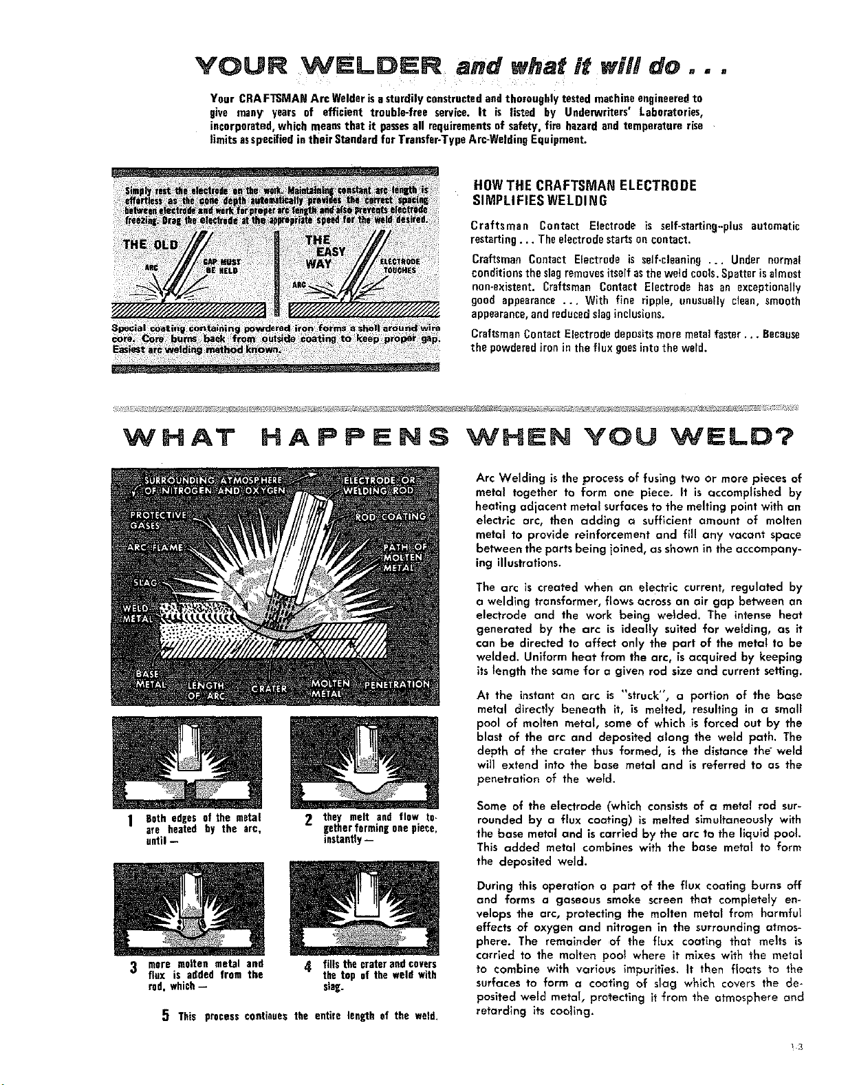
1 Beth edges of the metal
are heated by the arc,
until --
2 they melt and flow te-
EetherforminE onepiece,
instantly--
Arc Welding is the process of fusing two or more pieces of
metal together to form one piece. It is c=ccompiished by
heating adjacent metal surfaces to the melting point with an
electric arc, then adding o sufficient amount of molten
metal to provide reinforcement and fill any vacant space
between the parts being joined, as shown in the accompany-
ing illustrations.
The arc is created when an etectrlc current, regulated by
a welding transformer, flows across an air gap between an
electrode and the work being welded. The intense heat
generated by the arc is ideally suited for welding, c=sit
can be directed to affect only the part of the metal to be
welded. Uniform heat from the arc, is acquired by keeping
its length the same for a given rod size and current setting.
At the instant an arc is "struck", a portion of the base
metal directly beneath it, is melted, resulting in a small
pool of molten metal, some of which is forced out by the
blast of the arc and deposited along the weld path. The
depth of the crater thus formed, is the distance the weld
will extend into the base metal and is referred to as the
penetration of the weFd.
Some of the electrode (which consists of o metal rod sur-
rounded by a flux coating) is melted simultaneously with
the base metal and is carried by the arc to the liquid pool
This added metal combines with the base metat to form
the deposited weld.
3 more molten metal and
flux is added from the
rod, which--
5 This processcontinues the entire length of the weld,
4[ fills the craterand covers
the top of the weld with
slag.
During this operation a part of the flux coating burns off
and forms a gaseous smoke screen that completely en-
velops the arc, protecting the molten meta_ from harmful
effects of oxygen and nitrogen in the surrounding atmos-
phere. The remainder of the flux coating that melts is
carried to the molten pool where it mixes with the metal
to combine with various impurities. It then floats to the
surfaces to form a coating of slag which covers the de-
posited weld metal, protecting it from the atmosphere and
retarding its cooling.
_3
 Loading...