

Craftsman 113201372 Owner’s Manual
MODEL N_ °
113.201372 _
Serial
Number
Model and serial
number may be found
at the rear
of the cabinet.
You should record both
model and serial number
in a safe place for
future use,
CAUTION:
Read
230 AMP
DUAL RANGE
ARC WELDER
SAFETY
UNSTRUCTIONS
carefully
® assembly
e operating
® repair parts
Sold by SEARS, ROEBUCK AND CO., Chicago, IL 60684 U.S.A.
Part No. 61337 Printed in U SA
SAFETY gNSTRUCTIONS TO OPERATOR
For your own protection, read and observe all instructions
included in this manual as well as the following specific
safety precautions:
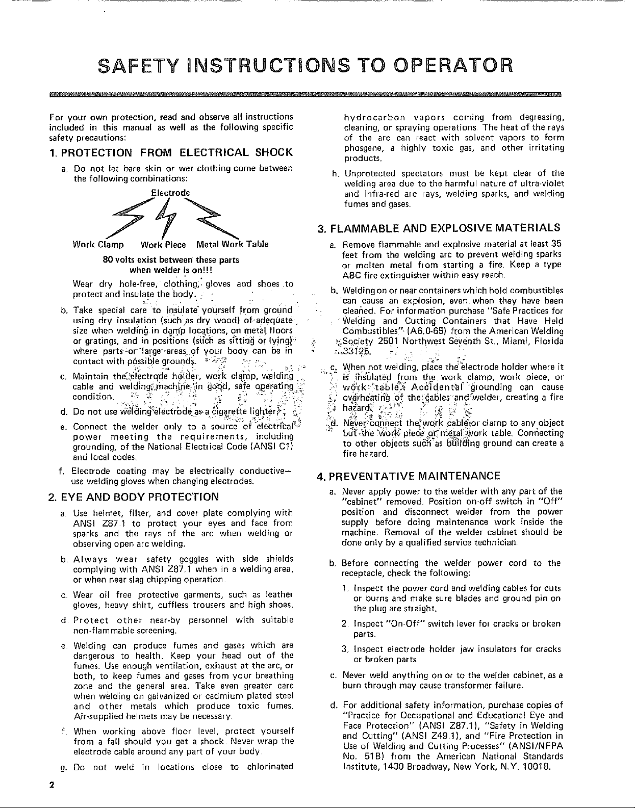
1, PROTECTION FROM ELECTRICAL SHOCK
a_ Do not let bare skin or wet clothing come between
the following combinations:
Electrode
Work Clamp
Work Piece Metal Work 'Table
80 volts exist between these parts
when welder is onH!
Wear dry hole-free, clothing,_ gloves and shoes to
protect and insulate the body.
b. Take special care to insulate" yourself from ground
using dry insulation (suchas dry wood) of-ad.equate
size when welding] in dam'p locations on metal floors
or grat ngs, and m poslt_ons (such as s=ttmgor lying ! "
where parts-or"large"areas of your body can be ir
contact with phssible ground_. ; ".;_ ro "_
C. Maintain the_.#l_ctr_de h_tder work clamp, w_ldin'g
cable and welding_:rnach_ne'._n_Qd, safe operating._
condition, : _ _; " " ,:' -' • "
Do not use weldm_ electrode as-aclaarette hg_ter, . -
e. Connect the welder only to a source of electncal'.-
power meeting the requirements, irrcluding
grounding, of the National Electrical Code (ANSI Cl)
and local codes.
f. Electrode coating may be electrically conductive-
use welding gloves when changing electrodes.
2. EYE AND BODY PROTECTION
a. Use helmet, filter, and cover plate complying with
ANSI Z87 1 to protect your eyes and face from
sparks and the rays of the arc when welding or
observing open arc welding,
b Always wear safety goggles with side shields
complying with ANSI Z871 when in a welding area,
or when near slag chipping operation
c. Wear oil free protective garments, such as leather
gloves, heavy shirt, cuffless trousers and high shoes.
d Protect other near-by personnel with suitable
non-flammable screening_
e
Welding can produce fumes and gases which are
dangerous to health, Keep your head out of the
fumes, Use enough ventilation, exhaust at the arc, or
both, to keep fumes and gases from your breathing
zone and the general area, Take even greater care
when welding on galvanized or cadmium plated steel
and other metals which produce toxic fumes
Ab-supplied helmets may be necessary
f When working above floor level, protect yourself
from a fall should you get a shock Never wrap the
electrode cable around arty part of your body
g Do not weld in locations close to chlorinated
2
hydrocarbon vapors coming from degreasing,
cleaning, or spraying operations The heat of the rays
of the arc can react with solvent vapors to form
phosgene, a highly toxic gas, and other irritating
products
h Unprotected spectators must be kept clear of the
welding area due to the harmful nature of ultra÷violet
and infra-red arc rays, welding sparks, and welding
fumes and gases
3. FLAMMABLE AND EXPLOSIVE MATERIALS
a Remove flammable and explosive material at least 35
feet from the welding arc to prevent welding sparks
or molten metal from starting a fire Keep a type
ABC fire extinguisher within easy reach.
b, Welding on or near containers which hold combustibles
can cause ar_explosion, even when they have been
cleaned= For information purchase "Safe Practices for
Welding one Cutting Containers that Have Hel d
Combustibles" (A6.0-65_ from the American Welding
:.Society 2501 Northwest Seventh St Miami, Florida
c. When not welding, place the electrode holder where it
"" i_ ihs'61ated from the work clamp, work piece, or'
wc_rk 'table_._ Ac_'idental grounding can cause
,_ overheating of the_ables'and_welder, creating a fire
haz_rd_ _ ::_" _ "
iild Never-c_nnect the_work cablelor clamp to any obJect
b_ _'he 'worl<:p e_e o_ me.to_ork tab e Conr]ecting
to other objects such as bu_l_mg ground can create a
fire hazard.
4. PREVENTATIVE MAINTENANCE
a. Never apply power to the welder with any part of the
"cabinet" removed_ Position on-off switch in "Off"
position and disconnect welder from the power
supply before doing maintenance work inside the
machine. Removal of the welder cabinet should be
done only by a qualified service technician,
b.
Before connecting the welder power cord to the
receptacle, check the following:
1 Inspect the power cord and welding cables for cuts
or burns and make sure blades and ground pin on
the plug are straighL
2 Inspect "On-Off" switch lever for cracks or broken
parts.
3 Inspect electrode holder jaw insulators for cracks
or broken parts.
c.
Never weld anything on or to the welder cabinet, as a
burn through may cause transformer failure.
d_
For additional safety information, purchase copies of
"Practice for Occupational and Educational Eye and
Face Protection" (ANSI Z87.1), "Safety in Welding
and Cutting" (ANSI Z49.1), and "Fire Protection in
Use of Welding and Cutting Processes" (ANSI/NFPA
No. 518) from the American National Standards
institute, 1430 Sroadway, New York, N.Y 10018_
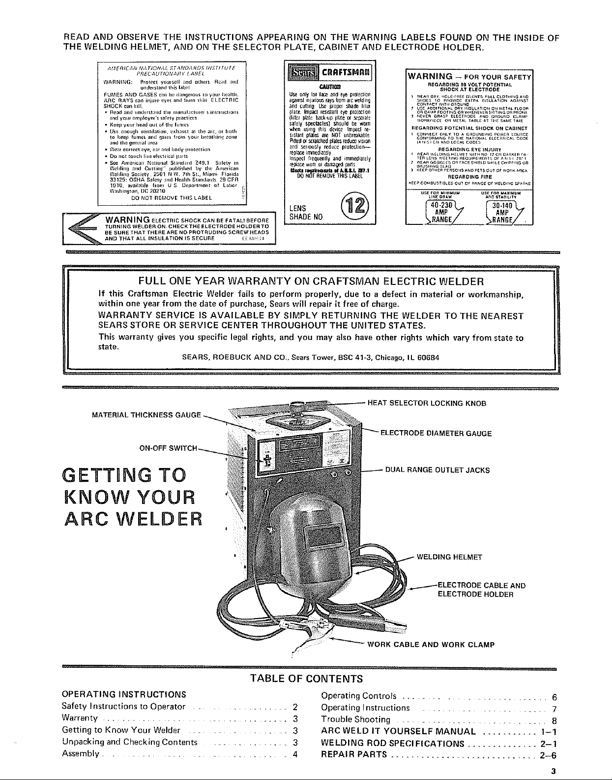
READANDOBSERVETHEINSTRUCTIONSAPPEARINGONTHEWARNINGLABELSFOUNDONTHEINSIDEOF
THEWELDINGHELMET,ANDONTHESELECTORPLATE,CABINETANDELECTRODEHOLDER.
_MERIEAN N,_ 71ON,_L ST,INI,),_RDS hV_TITUTE
WARNII_G: prolel:I VotJt_ell _t_d {_thefs _e;l(I ;_f_{I
F UJ%_ES AND GASES c;lll he (i,ln{J_ fal_s tn ymJl he_hh
ARC RAYS call inlllle eyel and hum stroll ELECTRIC
SHOCK cml kill
• Be,_d and understand _l_e incm_Hanh_fef _ =nslnJ_io_t_
• Keep your head aut of _1_ h_nles
• U_a enmJ_h Vel_il_iOl_, _xha_Jst al Ihe ;_,c, ot boUI
• Wear cot _ecl eye, _ar _nd body ltlo_ectlon
• Do I_O_ _ouch llve elec_ rical I)aFt_
• See American National Si,_nIt,_f(I Z49.1 S_lety in
WARNING ELeCTR,C SHOCK CAN BE FATALt BEFORE
TURNING WELDER ON CHECK THE ELECTRODE HOLDER TO
BE SURE THAT THERE ARE NO PROTRUDING SCREW HEADS
AND THAT ALL INSULATION IS SECURE _ _ll!! 2
PttEC,_UTION_RY I Af]EL
unders14_mt lh_ I_bel
and yo_Jt amployef's _alely pr acllce_
lo kee I) _ume_ and _ase_ from 7o_f I_re;_lhi_ I z_)m_
and the {Jene[al area
Wl!h_hlg mid Cliilin=j ¸' i)_JIilillle(I I}7 lhe Ait/eficalt
Wohthlg Sociel¥ 2501 N W 71h SI,, _,tbm_ Florida
33125; OSIIA Saf_W _1_{IHe_hh SI,_ndatds 29 CFR
1910, availal)_J_ hont U S Dep_tmenl o_ Labor
Washinglon , DC 20210
DO NOT R E_,_OV E THIS LABEL
CllRI0_
USe _lJ 101 IE,_ _n0 _y_ pi01egi0n
a_ins$ =nj_io_ rays Itom _c _ding
_nd culling US_ propel shade li!I_
plale _P¢_.I {ssi_IO _12 plo[_ction
(Iil_ pble b_ck_up plale• s_p_lale
salely spectacles) shou+d be worn
wheII U_l_ 0 this device It_cl fe-
sislanl plal_ ale DOT un_le.lkable
elted ¢_ s_la_h_d _Je_ t_u_ VISI_I
al_{_ 5_liO_$1 le_uc8 pI01eGIJ0r_--
{epia_eintricately
Inspecl {(equ_Ily an_ immedi31_ly
I_p_u_ _om ot d_m_ged p_tls
t,it4_ ir_ t¢=¢.¢_ =f JJ.I.L zr/1
DO NOT REMOVE "fills [/_3,E L
LENS
SHADENO
FULL ONE YEAR WARRANTY ON CRAFTSMAN ELECTRIC WELDER
If this Craftsman Electric Welder fails to perform properly, due to a defect in material or workmanship,
within one year from the date of purchase, Sears will repair it free of charge,
WARRANTY SERVICE IS AVAILABLE BY SIMPLY RETURNING THE WELDER TO THE NEAREST
SEARS STORE OR SERVICE CENTER THROUGHOUT THE UNITED STATES.
This warranty gives you specific legal rights, and you may also have other rights which vary from state to
state,
SEARS, ROEBUCK AND CO. Sears Tower_ BSC 41-3, Chicago, IL 60684
WARNING - FOR YOUR SAFET'_
R_GAR_ING B0 VOLT POTENTIAL
SHOC;{ AT ELECT}IOD_
REGARDING POTENTIAL SHOCK ON CABINET
COW,FORMING TO 1H_ _ATIONAL _L_CTnlCAL COD_
REGAROING £yE INJURY
REGARDING FIRE
LI_ O_AW _*nC eT_muY't
MATERIAL THICKNESS GAUGE.
ON-OFF SWITCH.-.
GETTING TO
KNOW YOUR
ARC WELDER
TABLE OF CONTENTS
OPERATING INSTRUCTIONS
Safety I nstructions to Operator .............................. 2
Warranty ............................................ 3
Getting to Know Your Welder ............................. 3
Unpacking and Checking Contents .......................... 3
Assembly ................................... 4
LOCKING KNOB
'IAMETER GAUGE
DUTLETJACKS
HELMET
AND
ELECTRODE HOLDER
WORK CABLE AND WORK CLAMP
Operating Controls ................................ 6
Operating Instructions ........................... 7
Trouble Shooting ............................... 8
ARC WELD IT YOURSELF MANUAL .............. 1-1
WELDING ROD SPECIFICATIONS ............... 2-1
REPAIR PARTS ..................................... 2-6
SPECIFICATIONS
Input Volts (AC): ........... 230
Hertz (Cycles): ................ 60
Output Amperage: ........ 30 to 140
40 to 230
Rated Input Amps: ............... 50
Short Circuit Input Amps: ......... 66
Fuse or Circuit
Breaker Required: ......... 50 Amps
Arc Voltage: ............... 25
KVA: .................... 108
KW: ........................... 7 1
Max Open Circuit
Output Volts .......... 80
Power Factor ........... 66%
Duty Cycle: ........ 20 to 100%
Electrode Capacity: 1/16" to 3/16"
UNPACKING AND CHECKUNG CONTENTS
SET-UP INSTRUCTIONS
This Craftsman welder is shipped complete in one carton
In order to facilitate packaging, certain items have been
removed at the factory and must be assembled when
3 4
ASSEMBLY
TOOLS NEEDED
received by the purchaser Remove all items from the
carton and identify item as shown in the exploded view
illustration These "Loose Parts" should be accounted for
before discarding any packaging material.
LOOSE PARTS LIST
Key
No. Part Name
1 WeldingHelmet(Partially assembled) ..........
2 Helmet bandassembly(Not Assembled) ........
3 Electrodecableassembly .........................
4 LoosePartsBag- Containing the following items:
Electrode Holder .....................................
Work Clamp ........................................... 1
Screw,Hex.-Hd.,1/4-20 x 3/4 in............... 1
Nut, Hex., 1/4-20 ........................... 1
Washer,Flat 17/64 in............................... 1
Loci{washer,1/4 in 1
O.ty.
i
t
1
1
I
1
,,lOinchwrenchScrewdriver(medium)
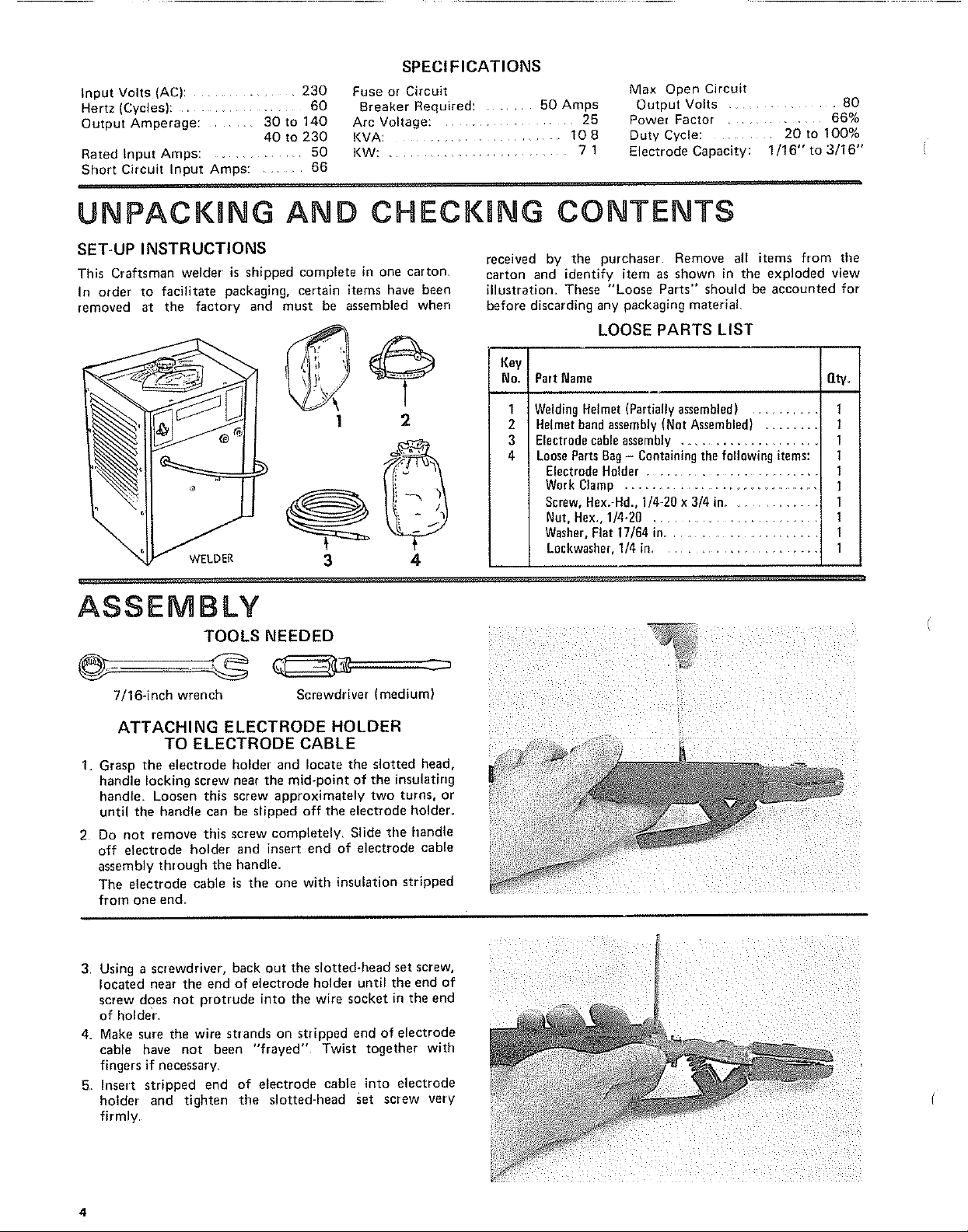
ATTACHING ELECTRODE HOLDER ............. ....
TO ELECTRODE CABLE
I. Grasp the electrode holder and locate the slotted head,
handle locking screw near the mid-point of the insulating
handle Loosen this screw approximately two turns, or
until the handle can be slipped off the electrode bolder..
2 Do not remove this screw completely. Slide tile handle
off electrode holder and insert end of electrode cable
assembly through the handle.
The electrode cable is the one with insulation stripped
from one end
3 Using a screwdriver, back out the slotted-head set screw,
located near the end of electrode holder until the end of
screw does not protrude into the wire socket in the end
of holder
4. Make sure the wire strands on stripped end of electrode
cable have not been "frayed" Twist together with
fingers if necessary.
5 Insert stripped end of electrode cable into electrode
holder and tighten the slotted-head set screw very
firmly
4
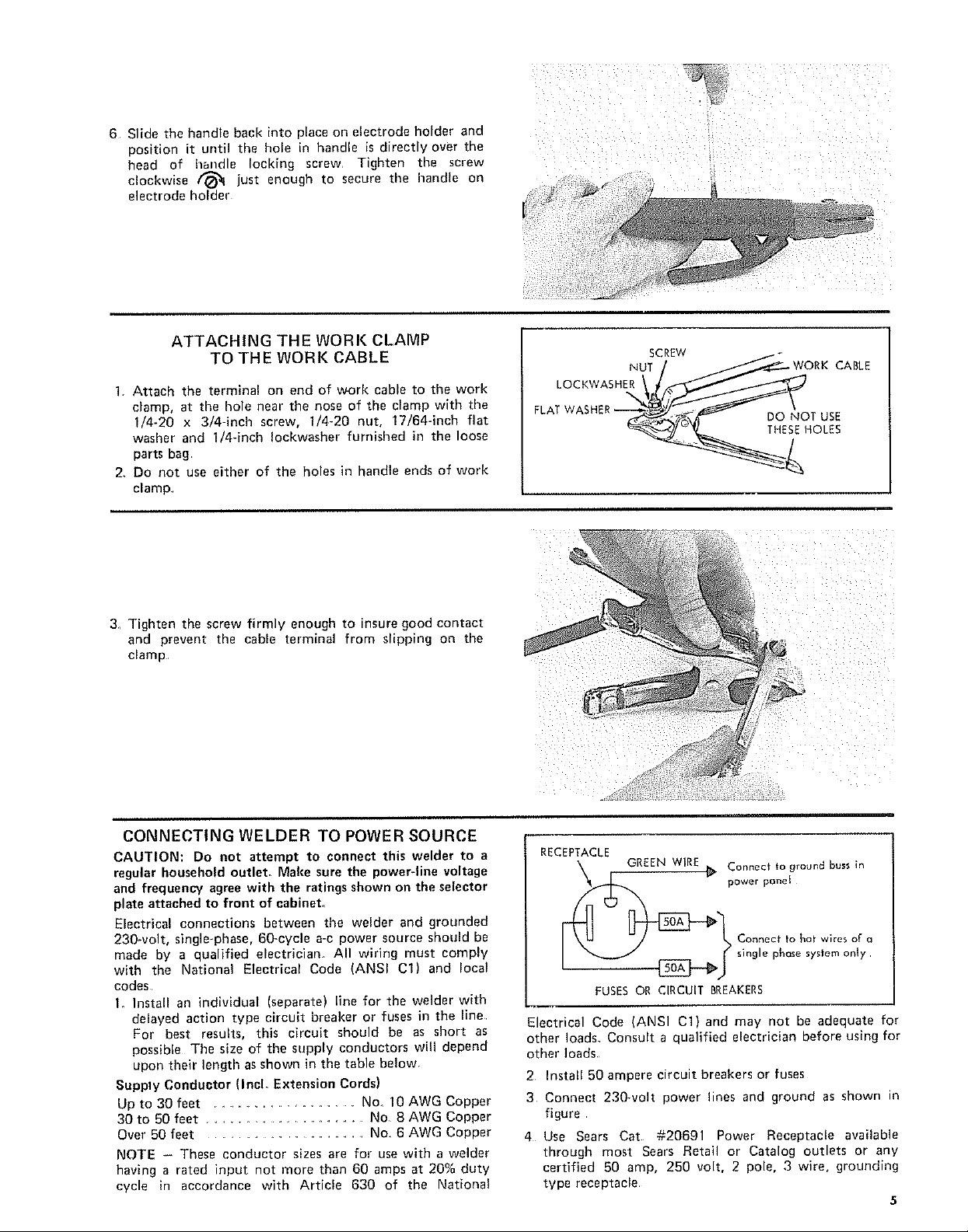
6 Slide the handle back into place on electrode holder and
position it until the hole in handle is directly over the
head of handle locking screw Tighten the screw
clockwise @ just enough to secure the Inandle on
electrode holder
_i_i ii _' _ i
ATTACHING THE WORK CLAMP
TO THE WORK CABLE
1. Attach the terminal on end of work cable to the work
clamp, at the hole near the nose of the clamp with the
1/4-20 x 3/4-inch screw, 1/4-20 nut, 17/64-inch flat
washer and I/4-inch Iockwasher furnished in the loose
parts bag
2_ Do not use either of the holes in handle ends of work
clamp
3_ Tighten the screw firmly enough to insure good contact
and prevent the cable terminal from slipping on the
clamp
SCREW
LOCKWASHNUTE_ HWORKCABLE
CONNECTING WELDER TO POWER SOURCE
CAUTION: Do not attempt to connect this welder to a
regular household outlet. Make sure the power-line voltage
and frequency agree with the ratings shown on the selector
plate attached to front of eabinet.
Electrical connections between the welder and grounded
230-volt, single-phase, 60-cycle a-c power source should be
made by a qualified electrician. All wiring must comply
with the National Electrical Code (ANSI C1) and local
codes
1. Install an individual (separate) line for the welder with
delayed action type circuit breaker or fuses in the line
For best results, this circuit should be as short as
possible The size of the supply conductors will depend
upon their length as shown in the table below
Supply Conductor (Incl. Extension Cords)
Up to 30 feet ............................ No_ 10 AWG Copper
30 to 50 feet ............................. No 8 AWG Copper
Over 50 feet ................................... No 6 AWG Copper
NOTE - These conductor sizes are for use with a welder
having a rated input not more than 60 amps at 20% duty
cycle in accordance with Article 630 of the National
RECEPTACLE
k GREENWIRE_. Connectto ground bussin
Connect to hot wires o[ Q
powerponet
single phase system only
FUSES OR CIRCUIT BREAKERS
Electrical Code (ANSI C1) and may not be adequate for
other loads Consult a qualified electrician before using for
other loads
2 Install 50 ampere circuit breakers or fuses
3 Connect 230wolt power lines and ground as shown in
figure
4 Use Sears Cat #20691 Power Receptacle available
through most Sears Retail or Catalog outlets or any
certified 50 amp, 250 volt, 2 pole, 3 wire, grounding
type receptacle.
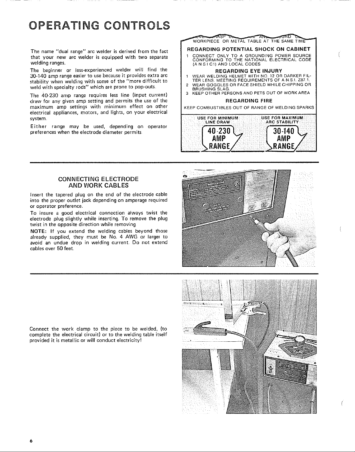
OPERATnNG CONTROLS
The name "dual range" arc welder is derived from the fact
that your new arc welder is equipped with two separate
welding ranges,
The beginner or less-experienced welder will find the
30-140 amp range easier to use because it provides extra arc
stability when welding with some of the "more difficult to
weld with specialty rods" which are prone to pop-outs
The 40-230 amp range requires less line (input current)
draw for any given amp setting and permits the use of the
maximum amp settings with minimum effect on other'
electrical appliances, motors, and lights, on your electrical
system,
Either range may be used, depending on operator
preferences when the electrode diameter permits
CONNECTING ELECTRODE
AND WORK CABLES
insert the tapered plug on the end of the electrode cable
into the proper outlet jack depending on amperage required
or operator preference.
To insure a good electrical connection always twist the
electrode plug slightly while inserting_ To remove the plug
twist in the opposite direction while removing
NOTE: If you extend the welding cables beyond those
already supplied, they must be No= 4 AWG or larger to
avoid an undue drop in welding current Do not extend
cables over 50 feet,
_TAL TABLE AT THE SAME TIM
REGARDING POTENTIAL SHOCK ON CABINET
1 CONNECT ONLY TO A GROUNDING POWER SOURCE
CONFORMING TO THE NATIONAL ELECTRICAL CODE
(A N S I C1) AND LOCAL CODES
1 WEAR WELDING HELMET WITH NO 12 OR DARKER FIL-
TER LENS MEETING REQUIREMENTS OF A NSI. Z87,1.
2 WEAR GOGGLES OR FACE SHIELD WHILE CHIPPING OR
BRUSHING SLAG.
3 KEEP OTHER PERSONS AND PETS OUT OF WORK AREA
KEEP COMBUSTIBLES OUT OF RANGE OF WELDING SPARKS
uSE FOR MINIMUM UsE FOR MAXIMUM
REGARDING EYE INJURY
REGARDING FIRE
LINE DRAW ARC STABILITY
AMP AMP Z
RANGE/
Connect the work clamp to the piece to be welded, (to
complete the electrical circuit) or to the welding table itself
provided it is metallic or will conduct electricity!
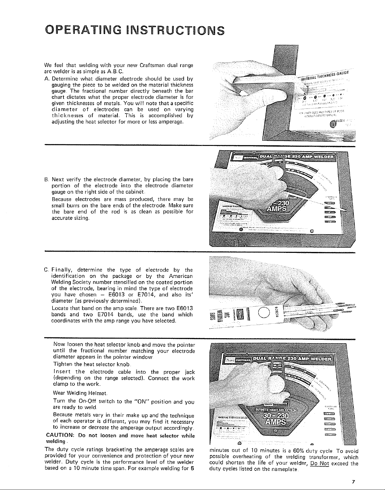
OPERATING RNSTRUCTIONS
We feel that welding with your new Craftsman dual range
arc welder is assimple asA B C
A Determine what diameter electrode should be used by
gauging the piece to be welded on the material thickness
gauge The fractional number directly beneath the bar
chart dictates what the proper electrode diameter is for
given thicknesses of metals You will note that a specific
diameter of electrodes can be used on varying
thicknesses of material. This is accomplished by
adjusting the heat selector for more or less amperage•
B Next verify the electrode diameter, by placing the bare
portion of the electrode into the electrode diameter
gauge on the right side of the cabinet
Because electrodes are mass produced, there may be
small burrs on the bare ends of the electrode Make sure
the bare end of the rod is as clean as possible for
accurate sizing,
C, Finally, determine the type of electrode by the
identification on the package or by the American
Welding Society number stencilled on the coated portion
of the electrode, bearing in mind the type of electrode
you have chosen - E6013 or E7014, and also its'
diameter (as previously determined)_
Locate that band on the amp scale There are two E6013
bands and two E7014 bands, use the band which
coordinates with the amp range you have selected•
Now loosen the heat selector knob and move the pointer
until the fractional number matching your electrode
diameter appears in the pointer window
Tighten the heat selector knob
Insert the electrode cable into the proper jack
(depending on the range selected), Connect the work
clamp to the work.
Wear Welding Helmet,
Turn the On-Off switch to the "ON" position and you
are ready to weld
Because metals vary in their make up and the technique
of each operator is different, you may find it necessary
to increase or decrease the amperage output accordingly,
CAUTION: Do not loosen and move heat selector while
welding
The duty cycle ratings bracketing the amperage scales are
provided for your convenience and protection of your new
welder_ Duty cycle is the performance level of the welder
based on a 10 minute time span. For example welding for 6
minutes out of 10 minutes is a 60% duty cycle To avoid
possible overheating of the welding transformer, which
could shorten the life of your welder, Do Not exceed the
duty cycles listed on the nameplate
7
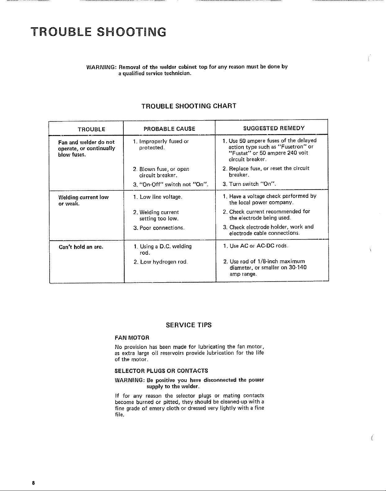
TROUBLE SHOOTING
WARNING: Removal of the welder cabinet top for any reason must be done by
a qualified service technician.
TROUBLE SHOOTING CHART
TROUBLE SUGGESTED REMEDY
Fan and welder do not
operate, or continually
blow fuses.
Welding current low
or weak,
Can't hold an arc.
PROBABLE CAUSE
1. Improperly fused or
protected_
2 Blown fuse, or open
circuit breaker_
3_"On-Off" switch not "On".
1. Low line voltage,
2_ Welding current
setting too Iow_
3, Poor connections.
1 Using a D.C. welding
rod.
2. Low hydrogen rod
1. Use 50 ampere fuses of the delayed
action type such as "'Fusetron" or
"Fustat" or 50 ampere 240 volt
circuit breaker.
2 Replace fuse, or reset the circuit
breaker.
3 Turn switch "On".
1_ Have a voltage check performed by
the local power company_
2. Check current recommended for
the electrode being used.
3, Check electrode holder, work and
electrode cable connections
1_Use AC or AC-DC rods
2, Use rod of 1/8-inch maximum
dian'leter, or' smaller on 30-140
amp range.
SERVICE TIPS
FAN MOTOR
No provision has been made for lubricating the fan motor,
as extra large oil reservoirs provide lubrication for the life
of the motor.
SELECTOR PLUGS OR CONTACTS
WARNING: Be positive you have disconnected the power
supply to the welder_
If for any reason the selector plugs or mating contacts
become burned or pitted, tiley should be cleaned-up with a
fine grade of emery cloth or dressed very lightly with a fine
file,
f
A COMPREHENSIVE
GUIDE FOR YOUR
NEW CRAFTSMAN
ARC WELDER AND
WHAT iT W_LL DO
CONTAINS:
INFORMATION ABOUT
o VARIOUS TYPES OF RODS
o USEFUL ACCESSORIES
TIPS ON CUTTING, WELDING
AND BRAZING
,,,J
Form No SP574-4 1-]
IJELD gT Y©U SELF
TABLE OF CONTENTS
Your WelderandWhat It Will Oo ............. 1-3
How the CraftsmanContactRodSimplifiesWelding 1-3
WhatHappensWhenYou Weld? .............. 1-3
ReadBeforaWelding ....................... 14
LearnBy Doing .......................... 1-5
PositionWelding ......................... 1-11
Cast-IronWelding ........................ 1-14
HardSurfacingWornCuttingEdges .......... 1-15
TheTwin CarbonArc Torch ............... 1-16
CuttingandOther MiscellaneousOperations ..o 1-17
Inert-GasMetal-ArcWelding ................ 1-19
Page
Read this Manual carefully for additional welding information.
1o2
SEARS, ROEBUCK AND COMPANY
AND SIMPSONS-SEARS LIMITED
YOUR WELDER and what it will do =°.
Your CRAFTSMAN Arc Welderisasturdilyconstructedendthoroughlytestedmachineengineeredto
give many years of efficient trouble-free service. It is listed by Underwriters' Laboratories,
incorporated,which meansthat it passesall requirementsof safety,fire hazardand temperaturerise
limitsasspecifiedin theirStandardfor Transfer-TypeArc-WeldingEquipment,
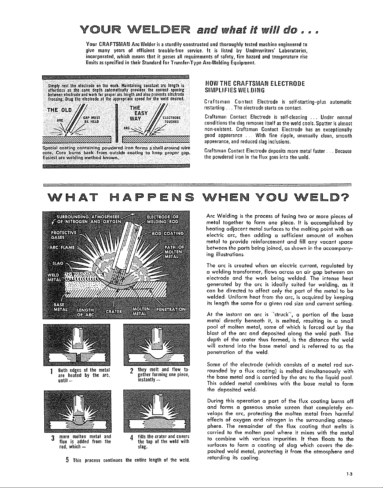
HOW THE CRAFTSMAN ELECTRODE
SIMPLIFIES WELDING
Craftsman Contact Electrode is self-starting-plus automatic
restarting , The electrodestartson contacL
Craftsman Contact Electrode is serf-cleaning..... Under normal
conditionstheslagremovesitselfasthe weld cools,Spatter is almost
nen-existenL Craftsman Contact Electrode has an exceptionally
good appearance _ With fine ripple, unusually clean, smooth
appearance,andreduced slaginclusions
CraftsmanContact Electrode depositsmore metalfaster . Because
the powderediron in the flux goesintotile weld_
1 Beth edges of the metal
are heated by the arc,
until--
2 they melt and flow to
gether formingone piece,
instantly--
Arc Welding is the process of fusing two or more pieces of
metal together to form one piece. It is accomplished by
heating adjacent metal surfaces to the melting point with an
electric arc, then adding a sufficient amount of molten
metal to provide reinforcement and fill any vacant space
between the parts being joined, as shown in the accompany-
ing illustrations
The arc is created when an electric current, regulated by
a welding transformer, flows across an air gap between an
electrode and the work being welded, The intense heat
generated by the arc is ideally suited for welding, as it
can be directed to affect only the part of the metal to be
welded, Uniform heat from the arc, is acquired by keeping
its length the same for a given rod size and current setting,
At the instant an arc is "struck", a portion of the base
metal directly beneath it, is melted, resulting in a small
pool of molten metal, some of which is forced out by the
blast of the arc and deposited along the weld path, The
depth of the crater thus formed, is the distance the weld
will extend into the base metal and is referred to as the
penetration of the weld
Some of the electrode (which consists of o metal rod sur-
rounded by a flux coating) is melted simultaneously with
the base metal and is carried by the arc to the liquid pool
This added metal combines with the base metal to form
the deposited weld,
3 mere molten metal and
flux is added from the
rod, which-
5 This process continues the entire length of the weld
4 fills the crater andcovers
the top of the weld with
slag,
During th_s operation a part of the flux coating burns off
and forms a gaseous smoke screen that completely en-
velops the arc, protecting the molten metal from harmful
effects of oxygen and nitrogen in the surrounding atmos-
phere, The remainder of the flux coating that melts is
carried to the molten pool where it mixes with the metal
to combine with various impurities It then floats to the
surfaces to form a coating of slag which covers the de-
posited weld metal, protecting it from the atmosphere and
retarding its cooilng
I-3
 Loading...