

Craftsman 113198251, 113198211 Owner’s Manual
I SaveThisManual
ForFutureReference
I
10" ELECTRONIC
RADIAL SAW WITH
23" CABINET AND
1 DOOR
10" ELECTRONIC
RADIAL SAW WITH
LEG SET
Serial
Number
Model and serial numbers
may be found at the rear of
the base
You should record both
model and serial number in
a safe place for future use,
113°198211_\
113o19825t
10-.INCH ELECTRONUC
RADIAL SAW
CAUTION:
® Assembly
READ ALL
INSTRUCTIONS
CAREFULLY
Sold by SEARS, ROEBUCK AND CO., Chicago, JL. 60684 U.S.A.
Part No, SP5102 Printed in U,S,A
® Operating
® Repair parts
FULLONEYEARWARRANTYONCRAFTSMANRADIALSAW
!t within one year from the date of purchase, this Craftsman Radial Saw fails due to a defect in material or
workmanship, Sears wilt repair it, free of charge.
WARRANTY SERVICE IS AVAILABLE BY SIMPLY CONTACTING THE NEAREST SEARS SERVICE
CENTER/DEPARTMENT THROUGHOUT THE UNITED STATES,
This warranty applies only while this product is used in the United States.=
This warranty gives you specific legal rights and you may also have other rights which vary from state to state.
SEARS, ROEBUCK AND CO, DEPT. 698/73tA Sears Tower, Chicago, IL 60684
i1,1 ,,i,1,1111 i, ,,
Table of Contents
,i ,i,, i .... , ii III II
Section Title Page Numbers
Safety Information ......................................................... 3-6
Putting Your Saw Iogether. .............................................. 7-18
Location and Function of Controls ..................................... t9-22
Alignment of Blade ..................................................... 23-38
Digital Display .................................. ........................... 39-44
Electrica! Connections ......................................... 45-46
Crosscutting ............................................................... 47-53
Ripping .................................................................... 54-62
Cutting Accessories ................................................... 63-66
Recommended Accessories .................................................. 67
Glossary ..................................................................... 68
Helpful Hints .......................................................... 69-71
Maintaining Your Saw ................................................ 72-77
"[rouble Shooting ..................................................... 78-83
Parts Lists ............................................................. 84-99
2
Safety Information ......................
The operator's manual contains safety infor-
mation, instructions and signs for your protec-
tion against serious injuries, including:
I_x)ssof fingers, hand, arm or leg from contact
with the saw blade.
Eye injuries, including being blinded from
being hit by a thrown workpiece, workpiece
chips or pieces of the saw blade.
Impact injuries, including broken bones and
internal organ damage, from being hit by a
thrown workpiece, workpiece chips or pieces
of the saw blade.
Shock, electrocution, or burn injuries from
contact with wires, motor or other saw parts.
Safety Symbol and Signal Words
The safety information in this manual is high-
lighted by the following safety alert symbol.
Major Hazards
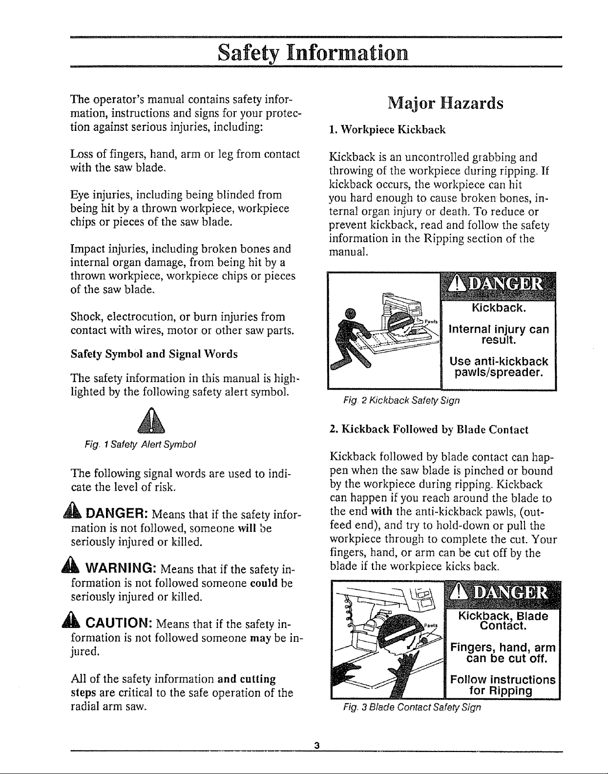
1. Workpiece Kickback
Kickback is an uncontrolled grabbing and
throwing of the workpiece during ripping. If
kickback occurs, the workpiece can hit
you hard enough to cause broken bones, in-
ternal organ injury or death. To reduce or
prevent kickback, read and follow the safety
information in the Ripping section of the
manual.
Fig 2 Kickback Safety Sign
&
Fig_ 1Safety Alert Symbol
The following signal words are used to indi-
cate the level of risk.
,_k DANGER: Means that if the safety infor-
mation is not followed, someone will be
seriously injured or killed.
WARNING: Means that if the safety in-
formation is not followed someone could be
seriously injured or killed.
,_k CAUTION: Means that if the safety in-
formation is not followed someone may be in-
jured.
All of the safety information and cutting
steps are critical to the safe operation of the
radial arm saw.
2. Kickback Followed by Blade Contact
Kickback followed by blade contact can hap-
pen when the saw blade is pinched or bound
by the workpiece during ripping. Kickback
can happen if you reach around the blade to
the end with the anti-kickback pawls, (out-
feed end), and try to hold-down or pull the
workpiece through to complete the cut. Your
fingers, hand, or arm can be cut off by the
blade if the workpiece kicks back.
Kickback, Blade
Contact.
Fingers, hand, arm
can be cut off.
Follow instructions
for Ripping
Fig. 3 Blade Contact Safety Sign
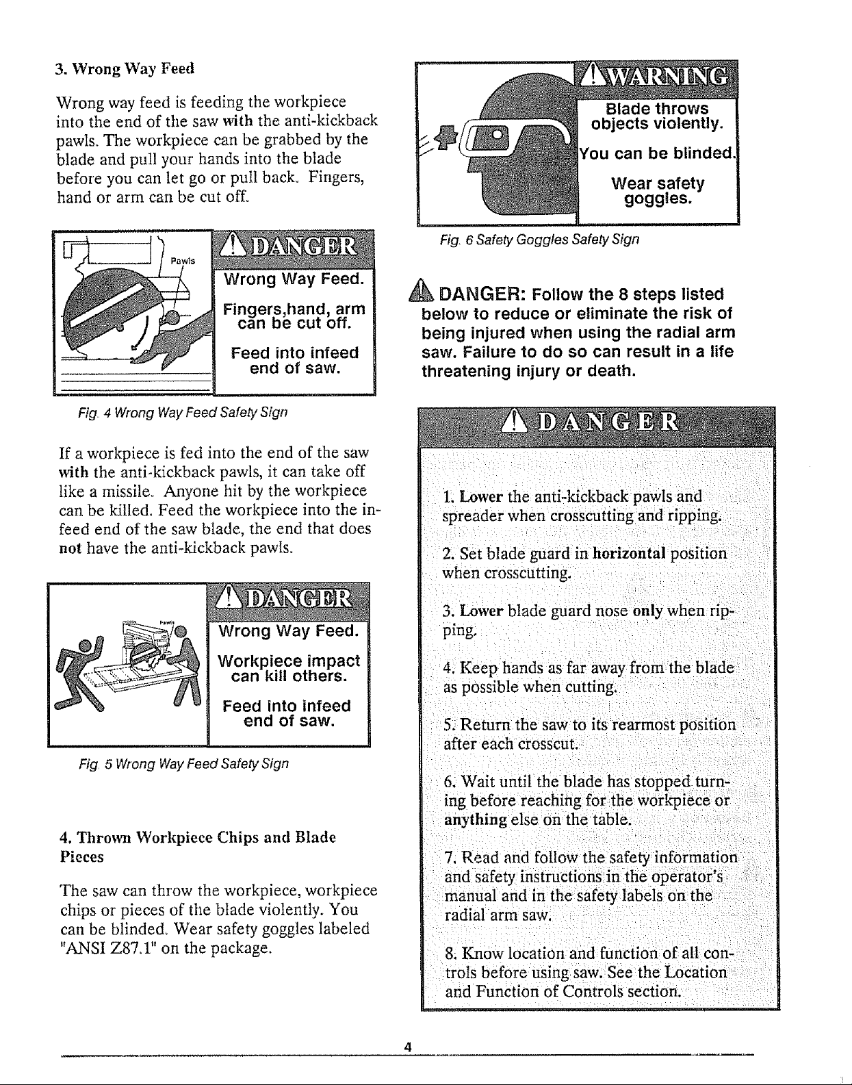
3. Wrong Way Feed
Wrong way feed is feeding the workpiece
into the end of the saw with the anti-kickback
pawls_ The worl_iece can be grabbed by the
blade and pull your hands into the blade
before you can let go or pull back. Fingers,
hand or arm carl be cut off°
Fig 4 Wrong Way Feed Safely Sign
If a workpiece is fed into the end of the saw
with the anti-kickback pawls, it can take off
like a missile. Anyone hit by the workpiece
can be killed. Feed the workpiece into the in-
feed end of the saw blade, the end that does
not have the anti-kickback pawls°
Fig, 6 Safety Goggles Safety Sign
DANGER: Follow the 8 steps listed
below to reduce or eliminate the risk of
being injured when using the radial arm
saw. Failure to do so can result in a life
threatening injury or death.
1. Lower the anti-kickback pawls and
spreader when crosscutting and ripping.
2. Set blade guard in horizontal position
when crosscutting.
Wrong Way Feed.
Workpiece impact
can kill others.
Feed into infeed
end of saw.
Fig 5 Wrong Way Feed Safely Sign
4. Thrown Workpiece Chips and Blade
Pieces
The saw can throw the workpiece, workpiece
chips or pieces of the blade violently. You
can be blinded_ Wear safety goggles labeled
"ANSI Z87A" on the package.
3. Lower blade guard nose only when rip-
ping.
4. Keep hands as far away from the blade
as possible when cutting.
5. Return the saw to its rearmost position
after each crosscut.
6, Wait until the blade has stopped turn-
[ng before reaching:for the workpiece or
anything else on the table.
7, Read and follow the: safety information
and safety instructions in the operator's
manual and in the safety labels on the
radia! arm saw,
8. Know location and function of a[1 con-
trols before using saw. See the Location
and Function of Controls section.
Personal Safety
Saw Safety
L Wear safety goggles labeled "ANSI Z87A"
on the package. Do not wear regular glasses,
they are not safety glasses.
2. Wear snug fitting clothes, short sleeve
shirts and nonslip footwear. Cover up or tie
long hair. Do not wear loose, baggy clothes,
gleves, neckties, rings, watches or any other
,jewelry.
3. Wear a dust mask, with your safety gog-
gles, if cutting operation is dusty.
4. Wear hearing protectors, ear plugs or
muffs, if you use the saw daily°
5. Keep good footing and balance. Don't over-
reach.
Work Area Safety
1. Keep children, pets and visitors out of the
work area.
2. Make the work area child proof. Remove
the yellow key from the red switch and place
it out of reach and sight. Lock work area.
!. Keep guards and anti-kickback pawls in
place and in working order.
2. Check for broken or damaged parts before
using saw. A damaged guard or other saw
part should be checked for alignment, bind-
ing, breakage and correct mounting to make
sure they are working properly. Repair or
replace damaged guards or other saw parts.
3. Unplug saw before doing maintenance,
making adjustments, and changing blades and
accessories.
4_Use clamps or vice to hold workpiece
when practical° It's safer than using your
hands and frees them to operate the saw.
5. Do not force the saw, saw blade or acces-
sories to do jobs they are not designed to do.
6. Make sure the yellow key is removed and
the red switch is in the off position before
plugging in the power cord.
7. Cut only wood, woodlike or plastic
materials. Do not cut metal materials.
3. Keep floors dry and free from sawdust, wax
or other slippery materials.
4. Keep work area clean, uncluttered and
well lighted_
5. Use the saw in a dry area. Do not use in
wet or damp area. Do not use outside.
6. Clear the table of all objects (adjusting
wrenches, tools, scraps of wood etc.) except
the workpiece to be cut, fixtures or clamps
before turning the saw on.
7. Do not do layout, assembly or setup work
on the table while the blade is turning.
8. Store items away from the saw. Do not
climb on the saw to reach items. Do not
stand on the table; the saw can tip oven
8. Secure the saw to floor, wall, bench or
table if it slides, tips or walks during use°
9. Feed the workpiece against the direction
of rotation of the blade when ripping.
!0. Turn the saw off before leaving work
area. Do not leave the saw until the blade
has stopped.
1t. Lock the rip and miter locks before
moving the saw from one location to another°
12. Turn the saw off and remove yellow key if
the blade jams° Do not try to free a jammed
workpiece with the saw on.
13. Turn the saw off if it vibrates excessively
or makes an unfamiliar noise. Correct any
problems before restarting saw.
14. Rip workpieces that are longer than the
diameter of the blade being used. Do not rip
a workpiece that is shorter than the diameter
of the blade being used.
15. Cut only one workpiece at a timer Do
not cut stacked workpieces or lay them edge
to edge for cutting,
Workpiece Support Safety
Safety Labels on the Radial Arm Saw
The following labels are on your radial arm
saw. Locate, read and follow the safety in-
structions and information contained in these
labels.
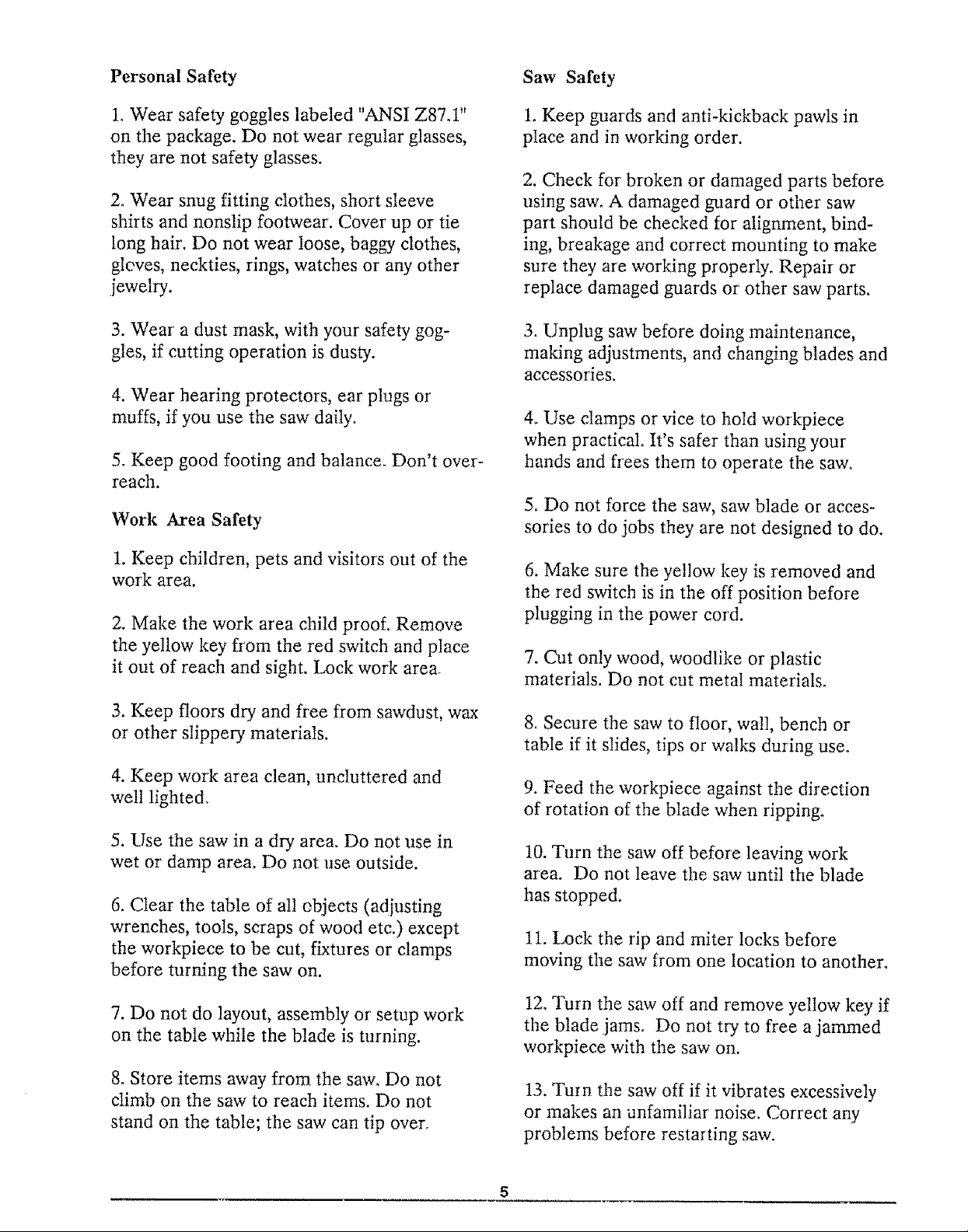
1. Wrong way feed label located on the out-
feed end of the blade guard.
1. Use additional supports for workpieces
which extend beyond the saw table. Large
workpieces can shift, twist, rise from table or
fall after they are cut.
2. Helpers can be hit by a thrown workpiece,
workpiece chips or pieces of the blade. Use
table extensions or other supports. Do not
use helpers.
3. Helpers can cause the workpiece to kick-
back_ Do not use other people to support or
assist in feeding or pulling the workpiece.
Use table extensions. See Recommended Ac-
cessories section of the manual°
4. When table extensions over 24 inches wide
are added to either side of the saw, make
sure you either bolt the saw to the floor or
support the outer end of the extension from
the floor with sturdy legs or an outrigger.
TO AVOID
INJURY DO NOT
FEED MATERIAL
INTO CUTTING
TOOL FROM
THIS END
Fig, 7 Wrong Way Feed Label
2. Safety instruction label located on the
front of the saw near tile handwheel.
IDAN ERI
FOR YOUR OWN SAFETY:
t Readandunderstandowner'smanua!
before operating machine.
2 Wear safety goggles complying with
ANSI Z87 t,
3 Keep hands out el pat h of saw blade
4 Know how to avoid "KICKBACKS','
5 Use "PUSH STICK '_ for narrow work
6 Never reach around the saw blade
7, Never perform any operation
"FREEHAND?
8 Returncarriagetothefutlrearposttion
after each cross-cut type operation
9, Shut off power and allow saw blade to
stop before adjusting or servicing
Blade Safety
1. Use blades marked for 3450 rpm or higher.
2. Do not use blades larger than 10 inches in
diameter.
3J Keep blade sharp and clean.
4_Do not cycle motor switch on and off rapid-
ly; the blade can loosen.
5. Do not overtighten the blade; the blade
collar can be warped°
Fig. 8 Safety Instruction Label
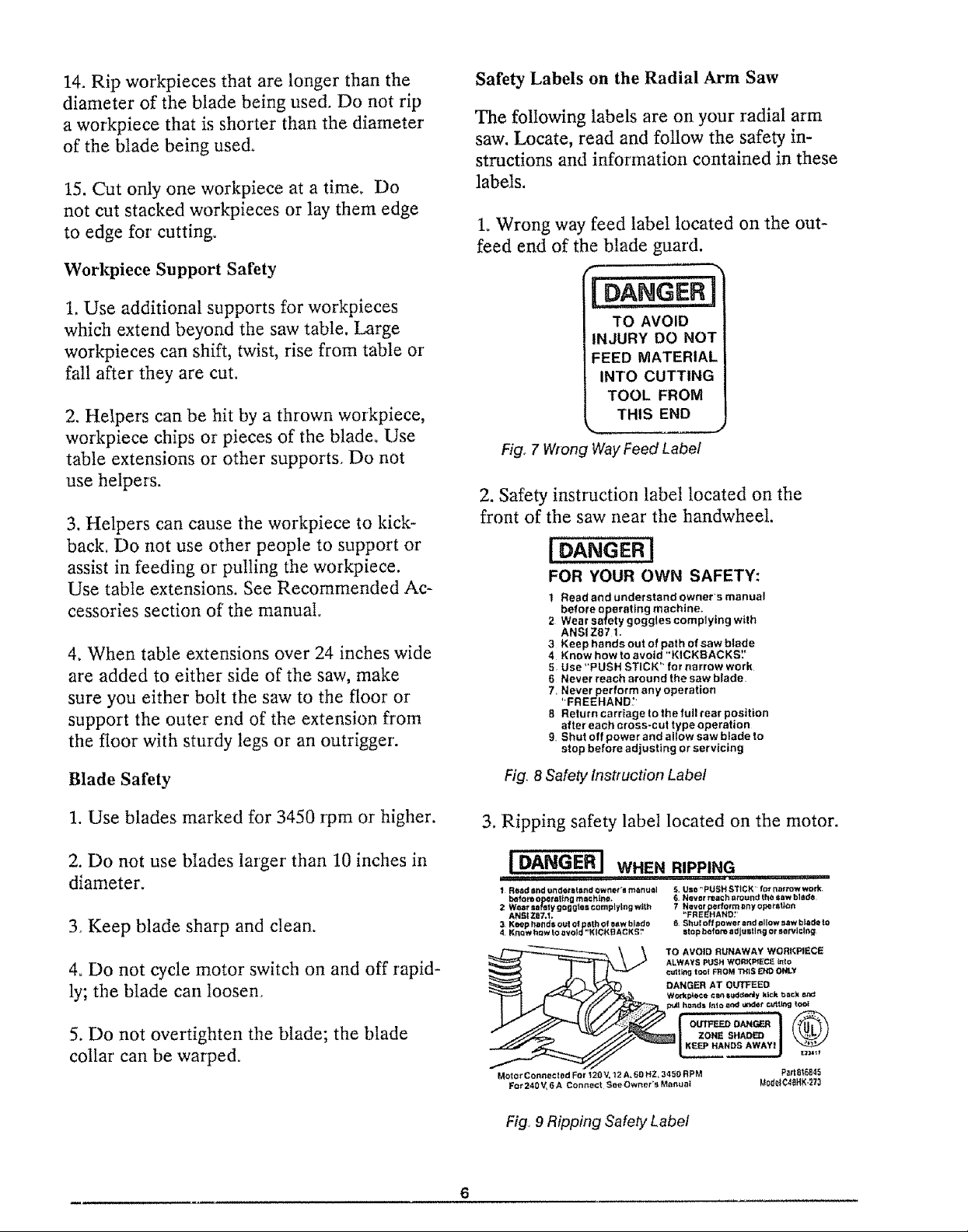
3. Ripping safety label located on the motor.
[ DANGER I WHENRIPPING
1 Rea=dBndunflot_l_ndownst'_rn_nu_l 5. Uso"PUSH_TICK' for naf_wwork,
before o_ toting mnchtna. _ N_ver reor:h around the sow bl0{]e
2 ANslW_t=Qfaty goggtos complyingwtt_zaT.1. 7 Nev_t,,FRE_p_/_NO/,ffotm_rt y opott_lto_t
31K_phallde_oulo(p_thofeawhlt_ds 8 ShuloffpowerandallowP.awb)Qdato
Krlow haw Io avoid "N tCN1EIA C I(=-;',' IStop before ad|u_llng or _tvlcllt,_
TO AVOID RUNAWAY WORKPIECE
, i, ,,,,11
,'_,%'L%"oW%';_ o%
DANGER AT OUTFEED
WO_p_CO Cart I_dd_y kick t_=¢X
MoIo_ Connected For 120 V, 12 A, 60 HZ, 3450 RPM P_'I 8t6815
For 240V_ 6 A Cont_ect See Owner's Manual MsdelCt_HK,273
Fig° 9 Ripping Safety Label
: Putting Your Saw Together .....................................
Your radial arm saw is easy to put together,
however it will take time. Ask a friend to
help, and follow these assembly instructions°
It is important for your safety, and for the
quality of your cuts, that the saw be put
together with care.
This manual was written for two different
models of the radia! arm saw: model
113, 198211 with cabinet and door, and model
t 13.198251 with leg set.
The following assembly sections should be
followed for both models:
Unpacking / Set up
Information
Attaching Handwheel
Mounting Motor
Mounting Saw
Attaching Trim Ledge and Trim Caps
Mounting Table Locks
Mounting the Front Table
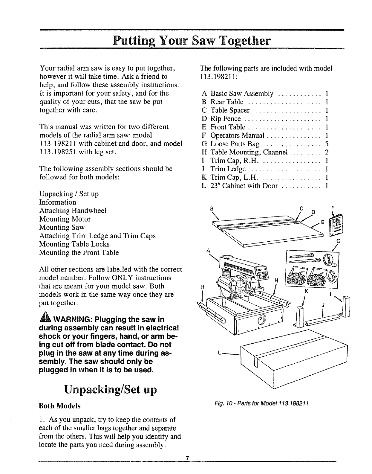
The following parts are included with model
I13_198211:
A Basic Saw Assembly ............ 1
B Rear Table .................... 1
C Table Spacer .................. 1
D Rip Fence ...................... 1
E Front Table ..................... 1
F Operators Manual ............... 1
G Loose Parts Bag ................ 5
H Table Mounting, Channel ........ 2
I Trim Cap, R.H ................... 1
J Trim Ledge .................... 1
K Trim Cap, L.H ................. 1
L 23" Cabinet with Door ........... 1
C F
G
A
\
All other sections are labelled with the correct
model number_ Follow ONLY instructions
that are meant for your model saw. Both
models work in the same way once they are
put together°
_ WARNING: Plugging the saw in
during assembly can result in electrical
shock or your fingers, hand, or arm be-
ing cut off from blade contact. Do not
plug in the saw at any time during as-
sembly. The saw should only be
plugged in when it is to be used.
Unpacking/Set up
Both Models
1. As you unpack, try to keep the contents of
each of the smaller bags together and separate
from the others. This will help you identify and
locate the parts you need during assembly.
H
Fig, 10 - Parts for Model !13,t98211
K
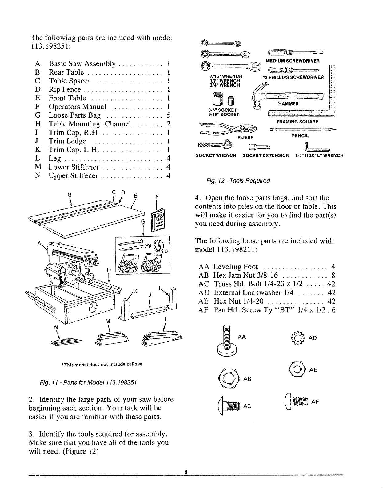
The following parts are included with model
113.198251:
A Basic Saw Assembly ............ !
B Rear Table .................... 1
C Table Spacer .................. t
D Rip Fence ........................ I
E Front Table ................................ 1
F Operators Manual ............... i
G Loose Parts Bag ............... 5
H Table Mounting Channel ........ 2
I Trim Cap, Roll ................. 1
J Trim Ledge .................... 1
K Trim Cap, Loll .................. 1
L Leg ...................................... 4
M Lower Stiffener ,................... 4
N UpperStiffener . .................. 4
B C D E F
MEDIUM SCREWDRIVER
7/16" WRENCH
112" WRENCH
3/4" WRENCH
314" SOCKET
9/16" SOCKET
PLIERS PENCIL
SOCKET WRENCH SOCKET EXTENSION 118" HEX "L" WRENCH
Fig° 12 - Tools Required
#2 PHILLIPS SCREWDRIVER
_T"? t;" g _ "t?t:'? t_
FRAMING SQUARE
4. Open the loose parts bags, and sort the
contents into piles on the floor or table. This
will make it easier for' you to find the part(s)
you need during assembly_
M
*This model does not include bellow_
Fig,_11 - Parts for Model 113.198251
2. Identify the large parts of your saw before
beginning each sectiom Your task will be
easier if you are familiar with these parts.
The following loose parts are included with
model 113.198211 :
AA Leveling Foot ....................... 4
AB Hex Jam Nut 3/8-16 .............. 8
AC Truss Hd, Bolt 1/4-20 x 1/2 ..... 42
AD External Lockwasher 1/4 ....... 42
AE Hex Nut 1/4-20 ....................... 42
AF Pan Hd. Screw Ty "BT" 1/4 x 1/2 • 6
AA _ AD
AF
3. Identify the tools required for assembly.
Make sure that you have all of the tools you
will need° (Figure 12)
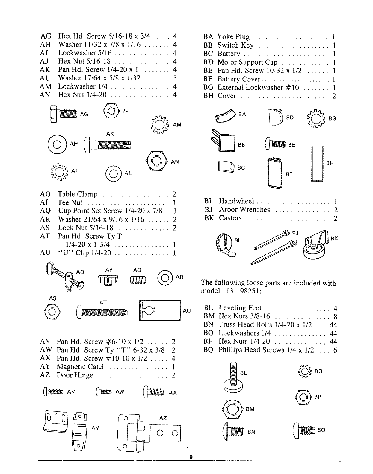
AG Hex Hd_ Screw 5/16-18 x 3/4 .... 4
AH Washer 11/32 x 7/8 x t/I6 ....... 4
AI Lockwasher 5/16 ....................... 4
AJ Hex Nut 5/16-18 ..................... 4
AK Pan Hd. Screw i/4-20 x 1 ........... 4
AL Washer I7/64 x 5/8 x 1/32 ....... 5
AM Lockwasher I/4 ................. 4
AN Hex Nut I/4-20 ................ 4
BA Yoke Plug ........................ 1
BB Switch Key ........................ t
BC Battery ............................ t
BD Motor Support Cap .................. t
BE Pan Hd. Screw 10-32 x 1/2 .......... I
BF Battery Cover, ....................... 1
BG External Lockwasher #10 ........ t
BH Cover. ............................. 2
_AG @ AJ
AK
_At _ AL
AO Table Clamp ...................... 2
AP Tee Nut ................................ 1
AQ Cup Point Set Screw 1/4-20 x 7/8 . 1
AR Washer 21/64 x 9/16 x !/t6 ...... 2
AS Lock Nut 5/16-18 ................. 2
AT Pan Hd. ScrewTyT
1/4-20 x I-3/4 ................... 1
AU "U" Clip 1/4-20 ................ t
AP AQ
AS
_BA _ BD 0 BG
Be
BF
BI Handwheel ........................ 1
BJ Arbor Wrenches .................. 2
BK Casters ............................. 2
BJ
BK
AR
The following loose parts are included with
model 1 I3.198251"
©
AV Pan Hd. Screw #6-I0 x 1/2 ...... 2
AW Pan Hdo Screw Ty "T" 6-32 x 3/8 2
AX Pan Hd. Screw #10-t0 x t/2 ..... 4
AY Magnetic Catch ....................... 1
AZ Door Hinge ....................... 2
_AV (_AW _AX
AT
AY
AU
BL Leveling Feet ......................... 4
BM Hex Nuts 3/8-16 ................. 8
BN Truss Head Bolts 1/4-20 x I/2 ,.. 44
BO Lockwashers 1/4 ................. 44
BP Hex Nuts 1/4-20 .............. 44
BQ Phillips Head Screws t/4 x !/2 .... 6
L
©
BM
BN
BQ
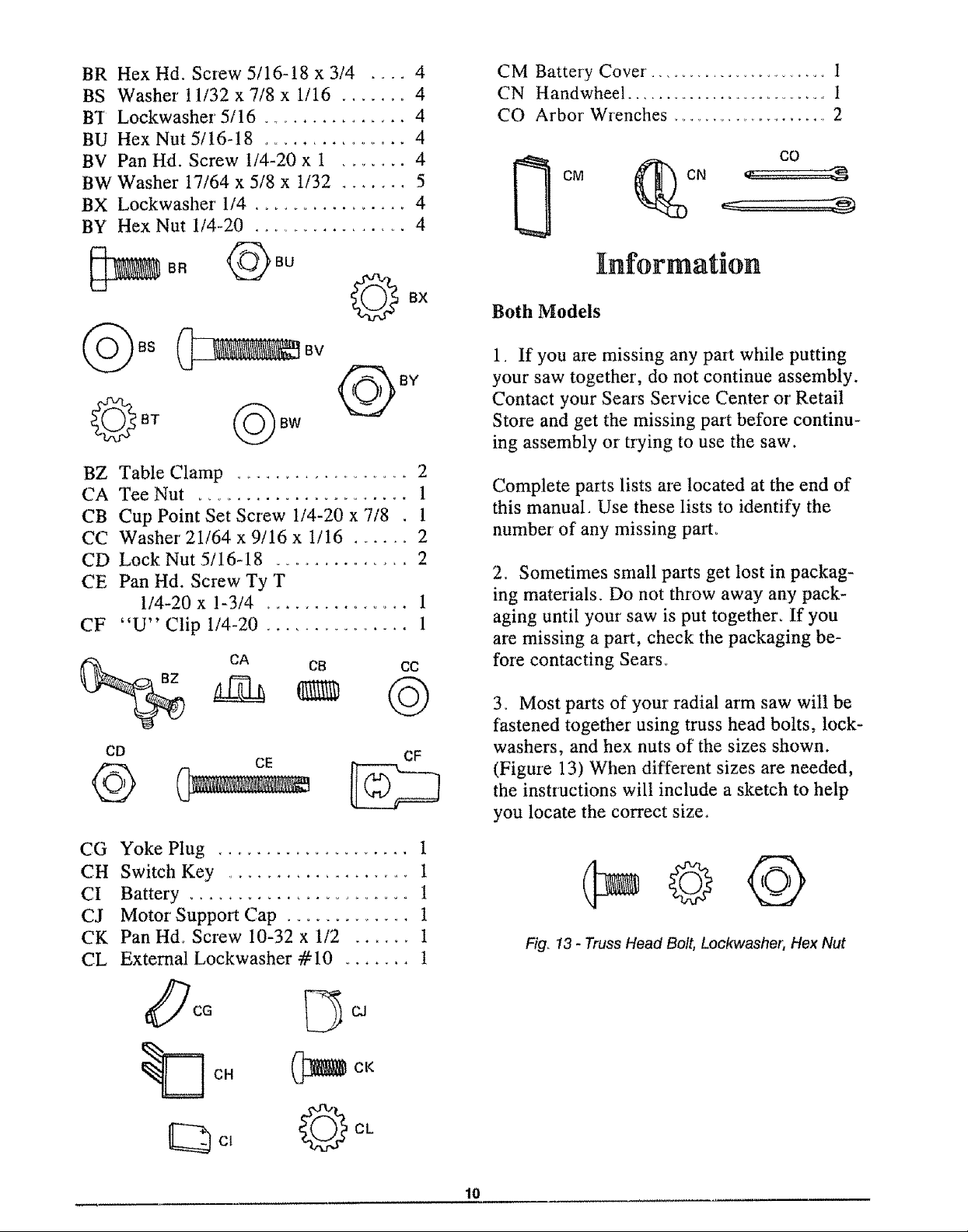
BR Hex Hd. Screw 5/16-18 x 3/4 .... 4
BS Washer 11/32 x 7/8 x 1/16 ....... 4
B'I Lockwasher 5/16 ................ 4
BU Hex Nut 5/16-18 ................ 4
BV Pan Hd. Screw t/4-20 x 1 ....... 4
BW Washer 17/64 x 5/8 x 1/32 ....... 5
BX Lockwasher 1/4 ................ 4
BY Hex Nut 1/4-20 ................ 4
CM Battery Cover _............................ 1
CN Handwheel ............................. 1
CO Arbor' Wrenches ......................... 2
CO
CM (_DCN
BR
BZ Table Clamp ...................... 2
CA Tee Nut ....................... 1
CB Cup Point Set Screw 1/4-20 x 7/8 . 1
CC Washer' 21/64 x 9/16 x t/16 ...... 2
CD Lock Nut 5/16-18 ................. 2
CE Pan Hd. Screw Ty T
1/4-20 x !-3/4 ............... 1
CF "U" Clip I/4-20 ................ 1
CD CE CF
BU
BV
BY
CA CB C@
Information
Both Models
1. If you are missing any part while putting
your saw together, do not continue assembly.
Contact your Sears Service Center or Retail
Store and get the missing part before continu-
ing assembly or trying to use the saw.
Complete parts lists are located at the end of
this manual, Use these lists to identify the
number of any missing part_
2. Sometimes small parts get lost in packag-
ing materials. Do not throw away any pack-
aging until your saw is put together. If you
are missing a part, check the packaging be-
fore contacting Sears°
3. Most parts of your radial arm saw will be
fastened together using truss head bolts, lock-
washers, and hex nuts of the sizes shown.
(Figure 13) When different sizes are needed,
the instructions will include a sketch to help
you locate the correct size,
CG Yoke Plug
CH Switch Key
CI
Battery ....................... !
CJ
Motor' Support Cap ............. 1
Pan Hd. Screw 10-32 x 1/2 ...... 1
CK
CL
External Lockwasher #10 ....... 1
OCG _ CJ
O c,
Fig_ 13 - Truss Head Belt, Lockwashet; Hex Nut
10
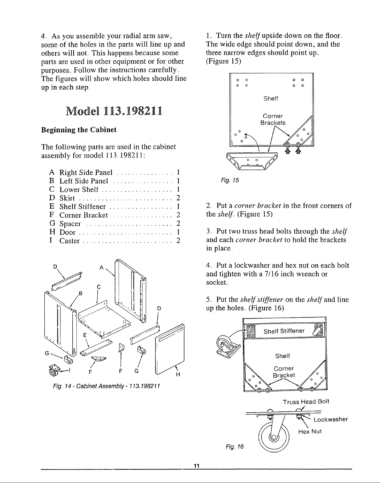
4, As you assemble your radial arm saw,
some of the holes in the parts will line up and
others will not, This happens because some
parts are used in other equipment or for other
purposes_ Follow the instructions carefully,,
The figures will show which holes should line
up in each step,
t, Turn the shelJ upside down on the floor°
The wide edge should point down, and the
three narrow edges should point up.
(Figure 15)
0 o 0 0
0 0 0 0
Shelf
Model 11t3.19821.1
Beginning the Cabinet
The following parts are used in the cabinet
assembly for model t 13_ 198211:
A Right Side Panel .................. 1
B Left Side Panel .................... 1
C Lower Shelf ....................... 1
D Skirt ................................... 2
E Shelf Stiffener ..................... 1
F Corner Bracket ................... 2
G Spacer ....................... 2
H Door° ............................... 1
I Caster ............................. 2
Corner /j
Brackets f
0 0 0 O0_
Fig. 15
2. Put a corner bracket in the front corners of
the shelf (Figure 15)
,3. Put two truss head bolts through the shelf
and each corner bracket to hold the brackets
in place,
4o Put a lockwasher and hex nut on each bolt
and tighten with a 7/16 inch wrench or
socket,
F G
Fig, 14 - Cabinet Assembly - 113.198211
5. Put the she!jstiffener on the shelf and line
D
up the holes. (Figure 16)
Truss Head Bolt
(m
Lockwasher
Hex Nut
Fig° 16
11
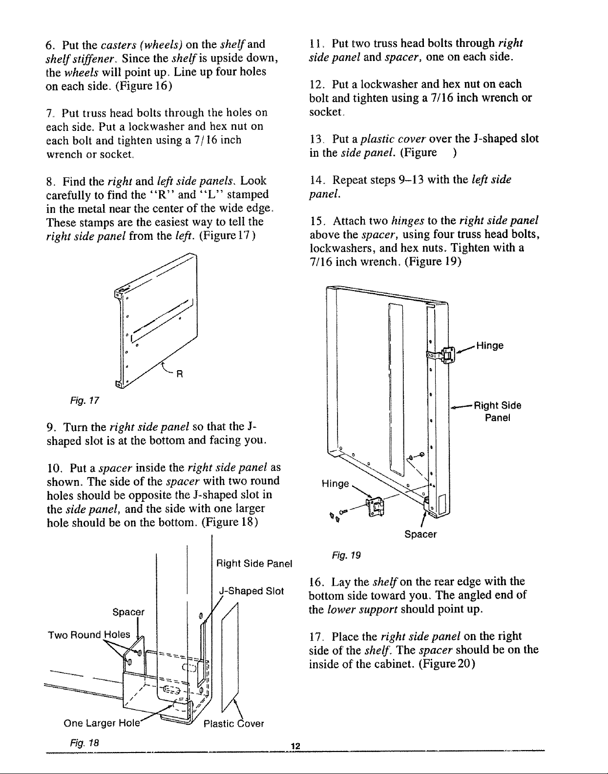
6. Put the casters (wheels) on the shelf and
shelfstiffenero Since the shelf is upside down,
the wheels will point up oLine up four holes
on each side. (Figme 16)
% Put truss head bolts through the holes on
each side. Put a lockwasher and hex nut on
each bolt and tighten using a 7/16 inch
wrench or socket°
1t_ Put two truss head bolts through right
side panel and spacer, one on each side.
12. Put a lockwasher and hex nut on each
bolt and tighten using a 7/16 inch wrench or
socket.
13. Put a plastic cover over the J-shaped slot
in the side panel. (Figure )
8. Find the right and left side panels, Look
carefully to find the "R" and "L" stamped
in the metal near the center of the wide edge.
These stamps are the easiest way to tell the
right side panel from the left. (Figure 1'7)
R
Fi9.17
9. Turn the right side panel so that the J-
shaped slot is at the bottom and facing you.
t4. Repeat steps 9-13 with the left side
panel.
15. Attach two hinges to the right side panel
above the spacer, using four truss head bolts,
lockwashers, and hex nuts. Tighten with a
7/16 inch wrench_ (Figure 19)
10. Put a spacer inside the right side panel as
shown_ The side of the spacer with two round
holes should be opposite the J-shaped slot in
the side panel, and the side with one larger
hole should be on the bottom. (Figure 18)
Right Side Panel
, -Shaped Slot
/
Spacer
One Larger Hole
Fig.la
Plastic Cover
%
Spacer
Fig. 19
!6. Lay the shelf on the rear edge with the
bottom side toward you_ The angled end of
the lower support should point up.
17. Place the right side panel on the right
side of the shelf. The spacer should be on the
inside of the cabinet. (Figure 20)
12
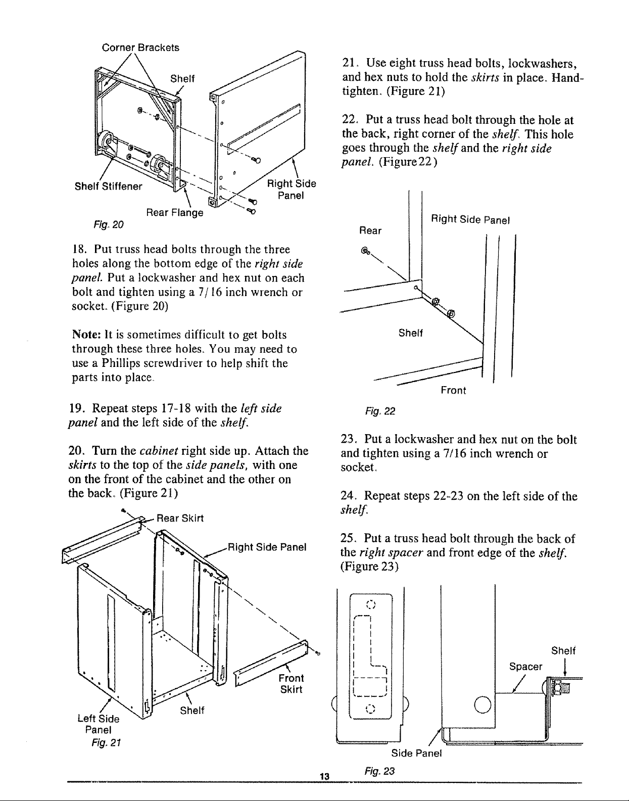
Corner Brackets
Shelf
21, Use eight truss head bolts, lockwashers,
and hex nuts to hold the skirts in place. Hand-
tighten. (Figure 21)
22, Put a truss head bolt through the hole at
the back, right corner of the shelf, This hole
goes through the shelf and the right side
panel. (Figure22)
Shelf Stiffener
Rear Flange
Fig_20
18, Put truss head bolts through the three
holes along the bottom edge of the right side
panel Put a lockwasher and hex nut on each
bolt and tighten using a 7/16 inch wrench or
socket. (Figure 20)
Note: It is sometimes difficult to get bolts
through these three holes. You may need to
use a Phillips screwdriver to help shift the
parts into place.
_" Right Side
Panel
19. Repeat steps 17-18 with the left side
panel and the left side of the shelf.
20. Turn the cabinet right side up. Attach the
skirts to the top of the side panels, with one
on the front of the cabinet and the other on
the back. (Figure 21)
Skirt
Rear
I Right Side Panel
I
I
Shelf
Front
Fig, 22
23. Put a lockwasher and hex nut on the bolt
and tighten using a 7/16 inch wrench or
socket.
24° Repeat steps 22-23 on the left side of the
shelf,
Left Side
Panel
Fig. 21
Shelf
Side Panel
\
\
\
Skirt
25. Put a truss head bolt through the back of
the right spacer and front edge of the shelf.
(Figure 23)
I
I
I
t
I
.... 2
Spacer !
©
Side Panel
13
Fig. 23
Shelf
26 Put a lockwasher and hex nut on the bolt
and tighten using a 7/16 inch wrench or
socket.
35. Adjust the lower' nut with the 9/16 inch
wrench until the leveling foot is at the desired
height°
27° Repeat steps 25-26 with the left spacer_
28_ Move the cabinet to the location where
you will use your saw.
29° Put a hex nut on each of the levelingfeeto
(Figure 24)
Fig° 24 - Hex Nut for Leveling Foot
30. Put the leveling feet through the holes in
the bottom of the side panels, at the four
corner's of the shelf
31. Put another hex nut on each of the
leveling feet and hand-tighten until they are
against the side panels_
WARNING: Saw blade can roll for-
ward toward you if the leveling feet are
not correctly adjusted. Workpiece or
saw can move unexpectedly if cabinet
rocks. Fingers, hand, or arm can be cut
off from blade contact. Adjust leveling
feet before using your saw.
36. Tighten the top nut by hand,
37_ Repeat steps 33-36 for the other' three
leveling feet if necessary.
38. Tighten all four bottom nuts using a 9/16
inch wrench.
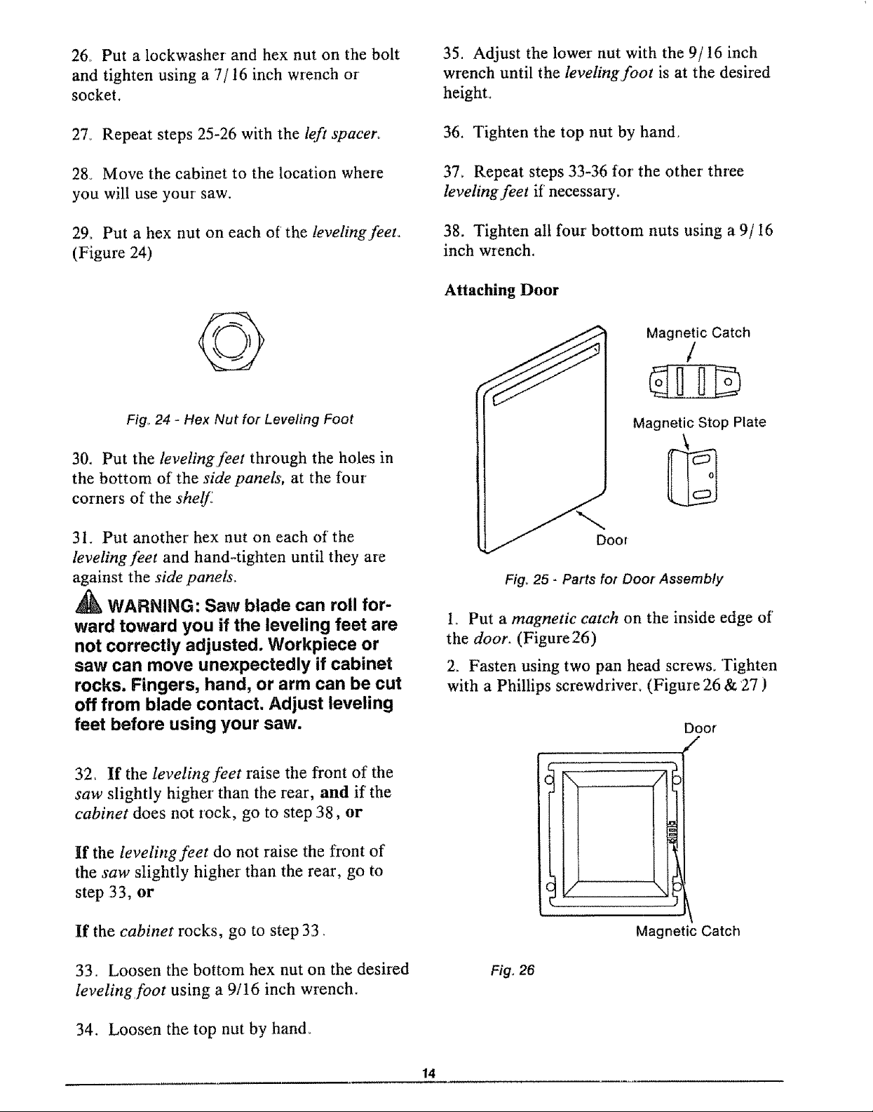
Attaching Door
Magnetic Catch
/
Magnetic Stop Plate
Fig, 25 - Parts for Door Assembly
Io Put a magnet& catch on the inside edge of'
the door. (Figure26)
2_ Fasten using two pan head screws. Tighten
with a Phillips screwdriver_ (Figure 26 & 27 )
Door
,,,-
32, If the leveling feet raise the front of tile
saw slightly higher than the rear, and if the
cabinet does not rock, go to step 38, or
If the leveling feet do not raise the front of
the saw slightly higher than the rear, go to
step 33, or
If the cabinet rocks, go to step 33,
33. Loosen the bottom hex nut on the desired
leveling foot using a 9/16 inch wrench.
34. Loosen the top nut by hand_
Magnetic Catch
Fig, 26
14
Fig° 27 - Pan Head Screw
3. Attach the door to the hinges on the side
panel using four plastite screws, Tighten with
a Phillips screwdriver. (Figure 28)
Fig_28 - Plastite Screw
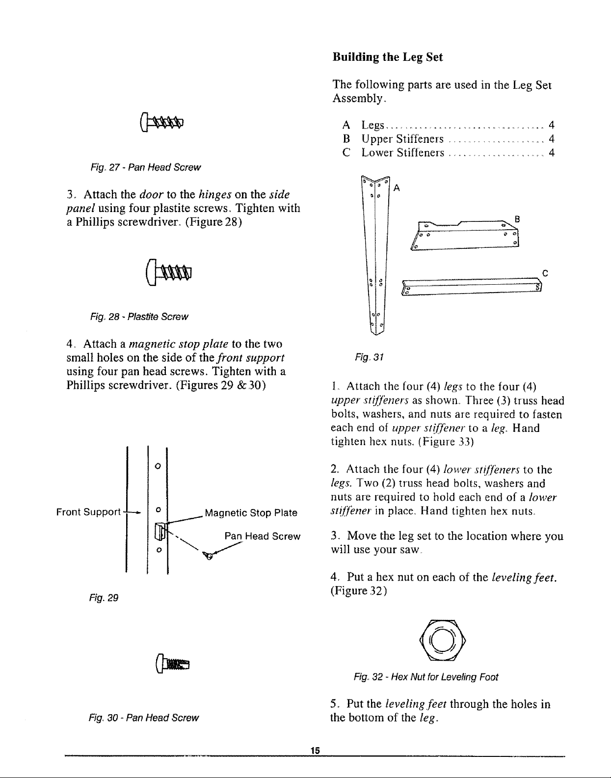
Building the Leg Set
The following parts are used in the Leg Set
Assembly.
A Legs .................................... 4
B Upper Stiffeners ....................... 4
C Lower Stiffeners ....................... 4
rA
B
C
4, Attach a magnetic stop plate to the two
small holes on the side of the front support
using four pan head screws. Tighten with a
Phillips screwdriver. (Figures 29 & 30)
o
Front Support
Fig. 29
0
/ Magnetic Stop Plate
tS{
_. Pan Head Screw
LII
o
Fig31
i. Attach the four (4) legs to the four (4)
upper st!ffeners as shown, Three (3) truss head
bolts, washers, and nuts are required to fasten
each end of upper stiffener to a leg. Hand
tighten hex nuts. (Figure 33)
2. Attach the four (4) lower st!ffeners to the
legs. Two (2) truss head bolts, washers and
nuts are required to hold each end of a lower
st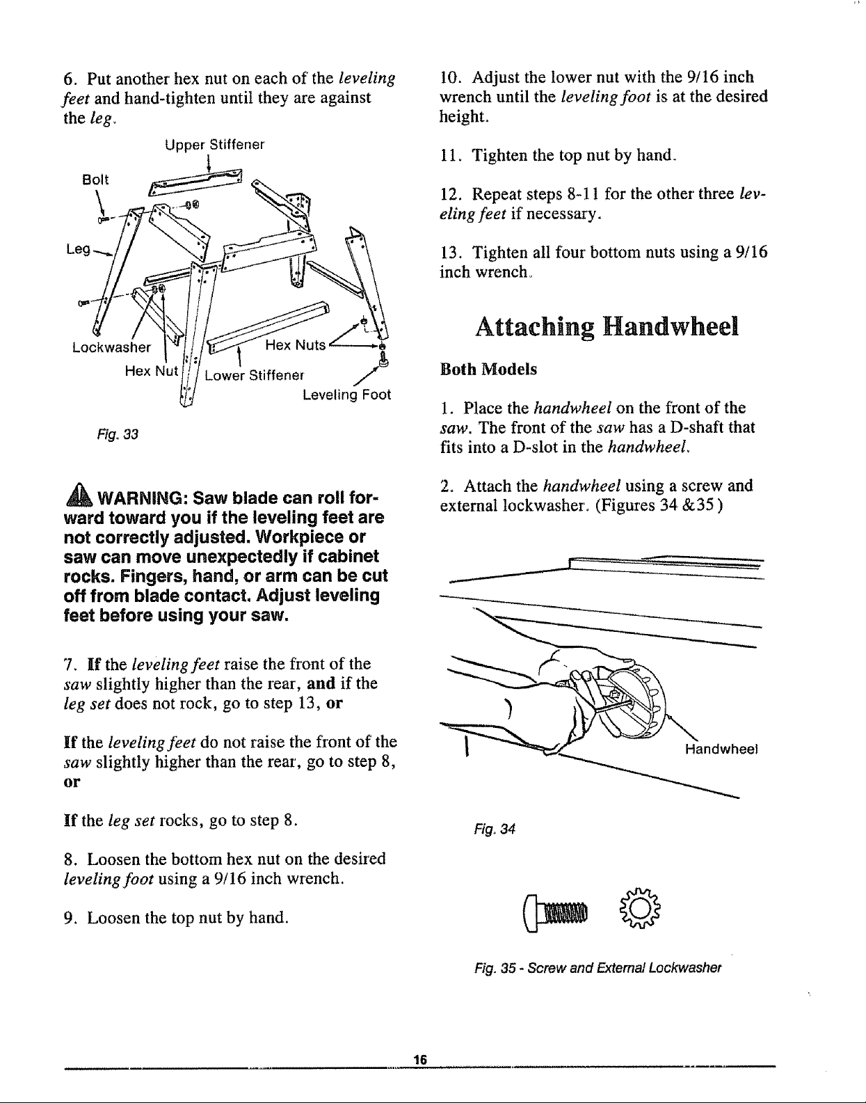
6. Put another' hex nut on each of the leveling
feet and hand-tighten until they are against
the leg_
10. Adjust the lower nut with the 9/16 inch
wrench until the leveling foot is at the desired
height.
Upper Stiffener
Bolt
Leg
Lockwasher Hex Nuts
Hex Nut Lower Stiffener /_
Leveling Foot
F/go33
WARNING: Saw blade can roll for-
ward toward you if the leveling feet are
not correctly adjusted. Workpiece or
saw can move unexpectedly if cabinet
rocks. Fingers, hand, or arm can be cut
off from blade contact. Adjust leveling
feet before using your saw.
11. Tighten the top nut by hand.
12. Repeat steps 8-1 t for the other' three lev-
eling feet if necessary.
13. Tighten all four bottom nuts using a 9/16
inch wrench°
Attaching Handwheel
Both Models
1. Place the handwheel on the front of the
saw. The front of the saw has a D-shaft that
fits into a D-slot in the handwheeL
2. Attach the handwheel using a screw and
extemat lockwasher. (Figures 34 &35 )
7. If the leveling feet raise the front of the
saw slightly higher than the rear, and if the
leg set does not rock, go to step 13, or
If the leveling feet do not raise the front of the
saw slightly higher than the rear, go to step 8,
OF
if the leg set rocks, go to step 8.
8. Loosen the bottom hex nut on the desired
leveling foot using a 9/16 inch wrench.
9. Loosen the top nut by hand.
Handwheel
Fig. 34
Fig. 35 - Screw and Extemal Lockwashet
16
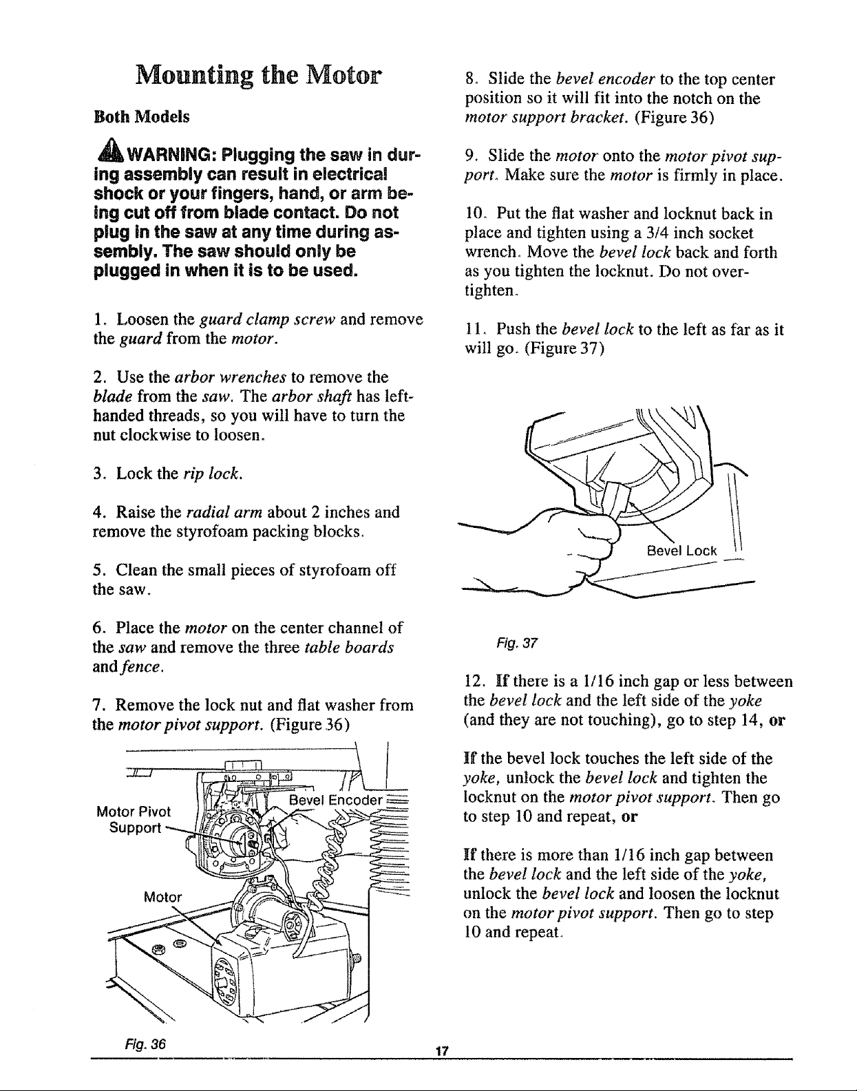
Mounting the Motor
Both Models
8o Slide the bevel encoder to the top center
position so it will fit into the notch on the
motor support bracket. (Figure 36)
_WARNING: Plugging the saw in dur-
ing assembly can result in electrical
shock or your fingers, hand, or arm be-
ing cut off from blade contact. Do not
plug in the saw at any time during as-
sembly. The saw should only be
plugged in when it is to be used.
1. Loosen the guard clamp screw and remove
the guard from the motor.
2. Use the arbor wrenches to remove the
blade from the saw. The arbor shaft has left-
handed threads, so you will have to turn the
nut clockwise to loosen.
3. Lock the rip lock.
4. Raise the radial arm about 2 inches and
remove the styrofoam packing blocks.
9. Slide the motor onto the motorpivot sup-
port_ Make sure the motor is firmly in place.
10. Put the flat washer and locknut back in
place and tighten using a 3/4 inch socket
wrench° Move the bevel lock back and forth
as you tighten the locknut. Do not over-
tighten°
11. Push the bevel lock to the left as far as it
will go. (Figure 37)
5. Clean the small pieces of styrofoam off
the saw.
6. Place the motor on the center channel of
the saw and remove the three table boards
and fence.
7. Remove the lock nut and flat washer from
the motorpivot support. (Figure 36)
Bevel Encoder
Motor Pivot
Support _
Motor
Fig, 37
12. If there is a 1/16 inch gap or less between
the bevel lock and the left side of the yoke
(and they are not touching), go to step 14, or
If the bevel lock touches the left side of the
yoke, unlock the bevel lock and tighten the
locknut on the motor pivot support. Then go
to step 10 and repeat, or
If there is more than t/16 inch gap between
the bevel lock and the left side of the yoke,
unlock the bevel lock and loosen the locknut
on the motor pivot support. Then go to step
10 and repeal
Fig. 36 17
13o Repeat steps 10-11 until the bevel lock
wilt not touch the left side of the ,yoke, and
the gap is not more than 1/16 inch_
14. Lock the bevel lock.
Attaching Trim Ledge and
Trim Caps
Both Models
15. Snap the yokeplug into place. The yoke
plug is in the loose parts bag
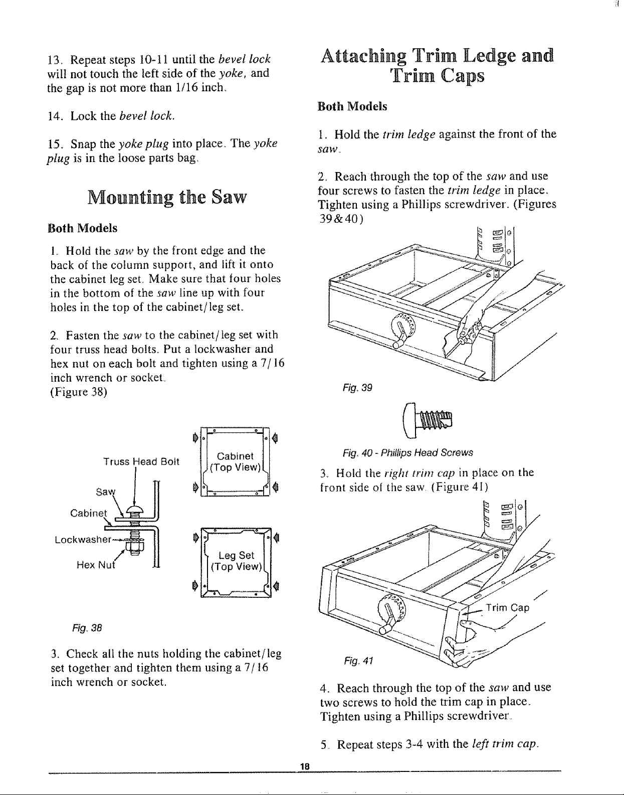
Mounting the Saw
Both Models
1 Hold the saw by the front edge and the
back of the column support, and lift it onto
the cabinet leg seL Make sure that four holes
in the bottom of the saw line up with four
holes in the top of the cabinet/leg seL
2. Fasten the saw to the cabinet/leg set with
four truss head bolts_ Put a lockwasher and
hex nut on each bolt and tighten using a 7/16
inch wrench or socket°
(Figuie 38)
1. Hold the trim ledge against the front of the
saw.
2.. Reach through the top of the saw and use
four screws to fasten the trim ledge in place.
Tighten using a Phillips screwdriver. (Figures
39&40)
Fig, 39
01°Foto[0
Truss Head Bolt
Cabinet
Loci
Hex Nut
Fig. 38
3. Check all the nuts holding the cabinet/leg
set together and tighten them using a 7/16
inch wrench or socket.
11Cabinet I /
Fig_40 - Phillips Head Screws
3. Hold the right trim cap in place on the
front side of the saw (Figure 41)
J
Trim Cap
Fig,.41
4. Reach through the top of the saw and use
two screws to hold the trim cap in place,
Tighten using a Phillips screwdriver_
5_ Repeat steps 3-4 with the left trim cap.
18
,i,
Location and Function of Controls
Fig_42 - Radial Saw Controls
I,II,l,ll,,
113 198211
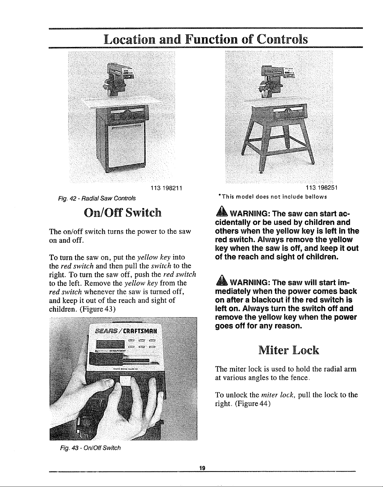
On/Off Switch
The on/off switch turns the power to the saw
on and off.
To turn the saw on, put the yellow key into
the red switch and then pull the switch to the
right. To turn the saw off, push the red switch
to the lefL Remove the yellow key from the
red switch whenever the saw is turned off,
and keep it out of the reach and sight of
children. (Figure 43)
WARNING: The saw can start ac-
cidentally or be used by children and
others when the yellow key is left in the
red switch. Always remove the yellow
key when the saw is off, and keep it out
of the reach and sight of children.
_, WARNING: The saw will start im-
mediately when the power comes back
on after a blackout if the red switch is
left on. Always turn the switch off and
remove the yellow key when the power
goes off for any reason.
Miter Lock
The miter lock is used to hold the radial arm
at various angles to the fence,
Fig. 43 - On/Off Switch
To unlock the miter lock, pull the lock to the
right, (Figure 44)
19
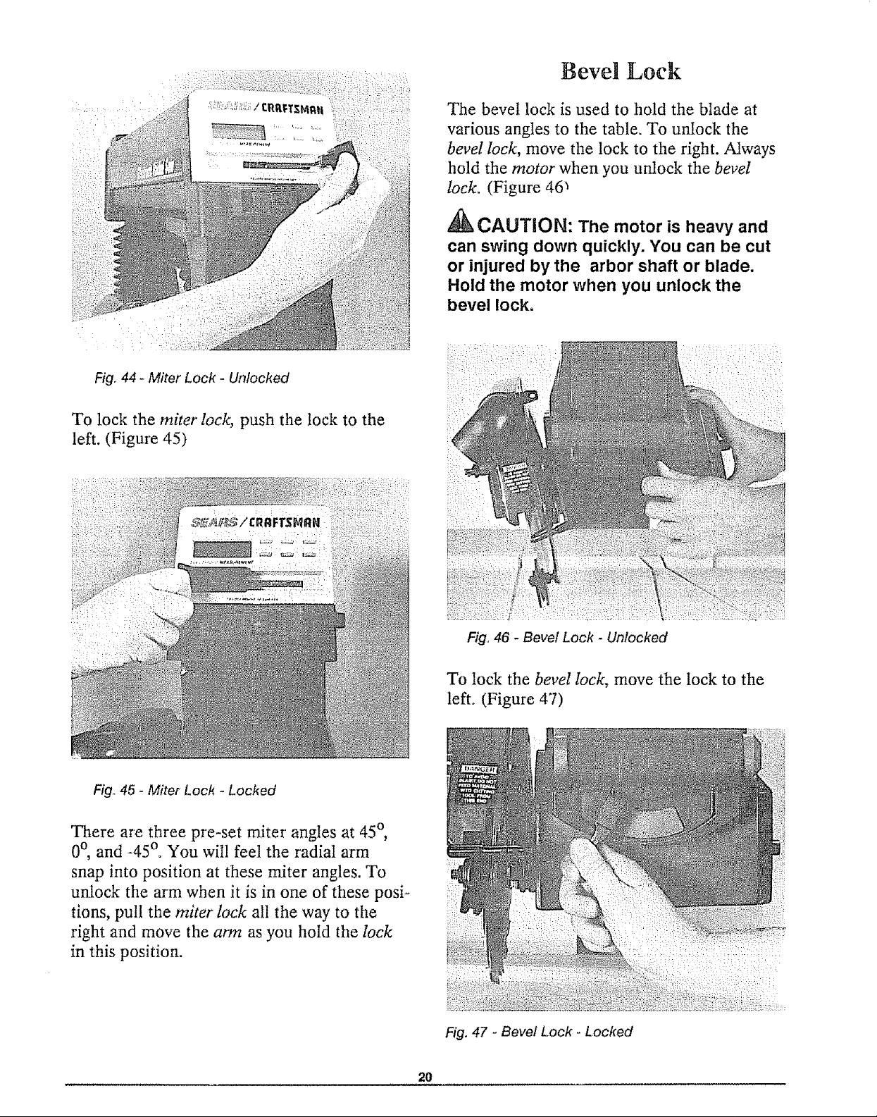
Fig,,44 - Miter Lock - Unlocked
To lock the miter lock, push the lock to the
left. (Figure 45)
Bevel Lock
The bevel lock is used to hold the blade at
various angles to the table. To unlock the
bevel lock, move the lock to the right. Always
hold the motor when you unlock the bevel
lock. (Figure 46_
,_k CAUTION: The motor is heavy and
can swing clown quickly. You can be cut
or injured by the arbor shaft or blade.
Hold the motor when you unlock the
bevel lock.
Fig.,45 - Miter Lock - Locked
There are three pre-set miter angles at 45°,
0°, and -45°° You will feel the radial arm
snap into position at these miter angles. To
unlock the arm when it is in one of these posi-
tions, pull the miter lock all the way to the
right and move the arm as you hold the lock
in this position.
Fig° 46 - Bevel Lock - Unlocked
To lock the bevel lock, move the lock to the
left. (Figure 47)
Fig. 47 - Bevel Lock - Locked
20
There are five pre-set bevel angles at -90°,
-45°, 0°, 45°, and 90°. To unlock the bevel
lock when the blade is at one of these angles,
move the bevel lock all the way to the right
and turn the motor while holding the lock in
this position.
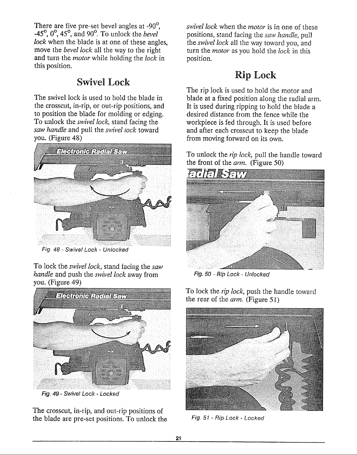
Swivel Lock
The swivel lock is used to hold the blade in
the crosscut, in-rip, or out-rip positions, and
to position the blade for molding or edging.
To unlock the swivel lock, stand facing the
saw handle and pull the swivel lock toward
you. (Figure 48)
swivel lock when the motor is in one of these
positions, stand facing the saw handle, puI!
the swivel lock all the way toward you, and
turn the motor as you hold the lock in this
position.
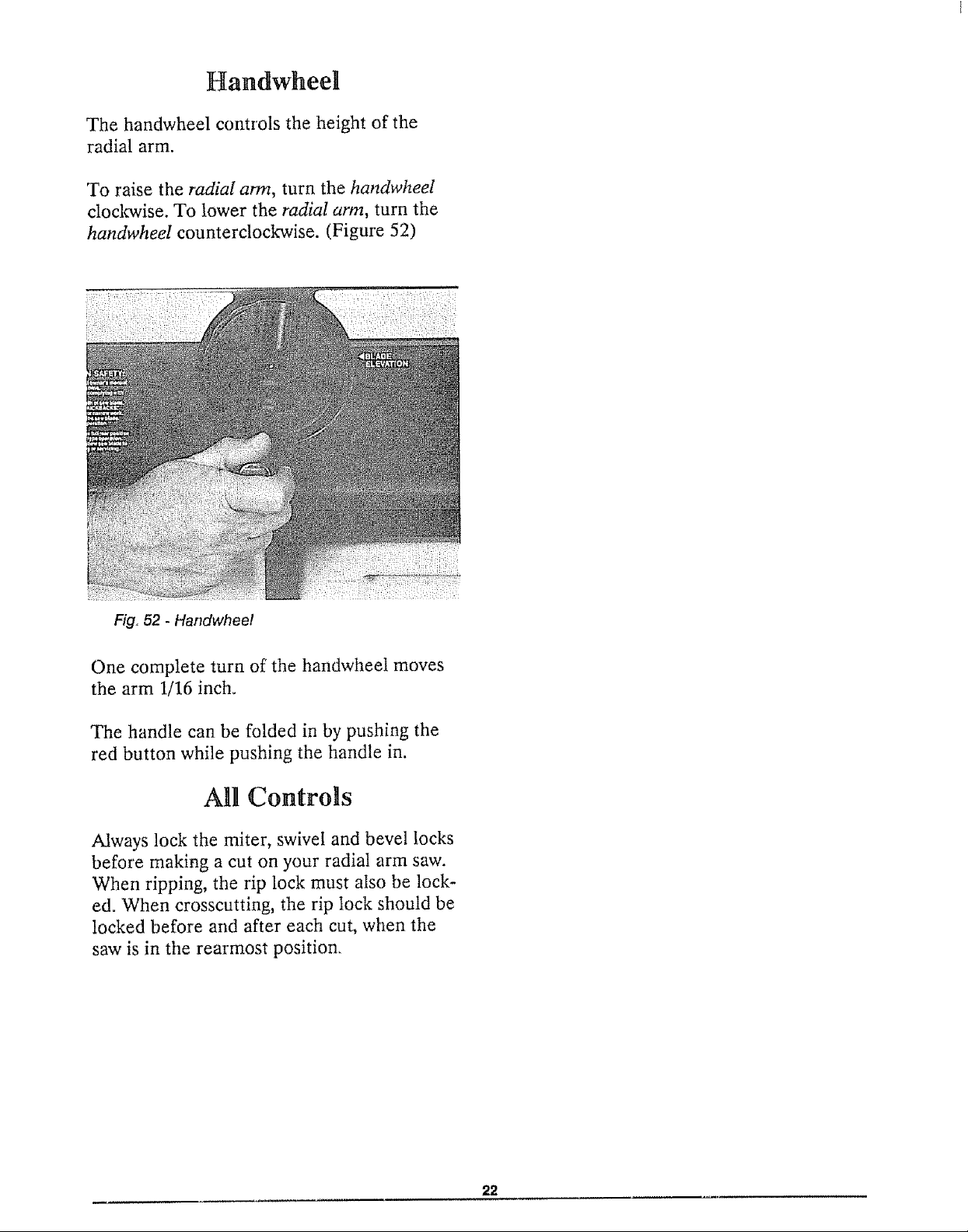
Rip Lock
The rip lock is used to hoId the motor and
blade at a fixed position along the radial arm.
It is used during ripping to hold the blade a
desired distance from the fence while the
workpiece is fed through. It is used before
and after each crosscut to keep the blade
from moving forward on its own.
To unlock the tip lock, pull the handle toward
the front of the ann. (Figure 50)
Fig 48 - Swivel Lock - Unlocked
To lock the swivel lock, stand facing the saw
handle and push the swivel lock away from
you. (Figure 49)
Fig° 49 - Swivel Lock - Locked
The crosscut, in-rip, and out-rip positions of
the blade are pre-set positions. To unlock the
Fig, 50 - Rip Lock - Unlocked
To lock the rip lock, push the handte toward
the rear of the arm. (Figure 5 I)
Fig, 51 - Rip Lock - Locked
21
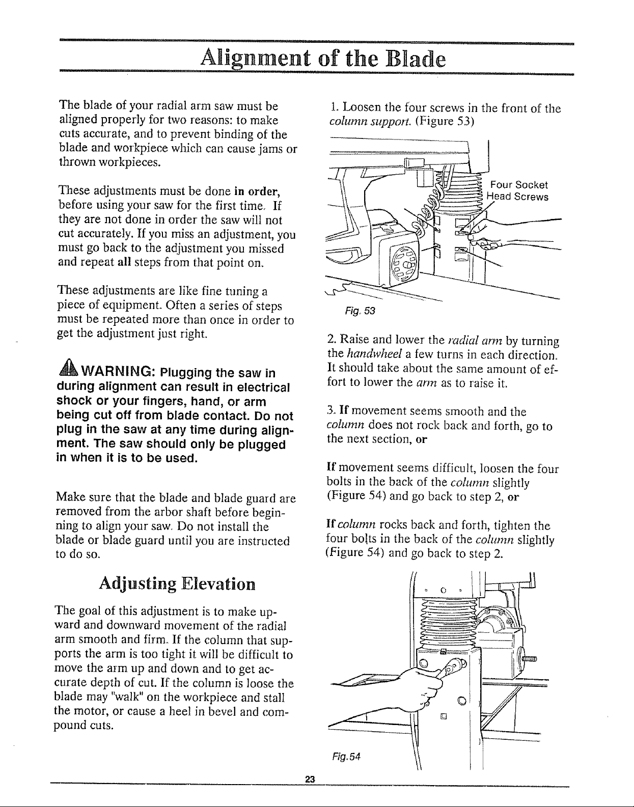
Handwheel
The handwheel controls the height of the
radial arm.
To raise the radial arm, turn the handwheel
clocle, vise. To lower the radial arm, turn the
handwheeI counterclockwise. (Figure 52)
Fig. 52 - Handwheel
One complete turn of the handwheel moves
the arm 1/16 inch.
The handle can be folded in by pushing the
red button while pushing the handle in.
All Controls
Always lock the miter, swivel and bevel locks
before making a cut on your radial arm saw.
When ripping, the rip lock must also be lock-
ed. When crosscutting, the rip Iock should be
locked before and after each cut, when the
saw is in the rearmost position.
22
The blade of your radial arm saw must be
aligned properly for two reasons: to make
cuts accurate, and to prevent binding of the
blade and workpiece which can cause jams or
thrown workpieces.
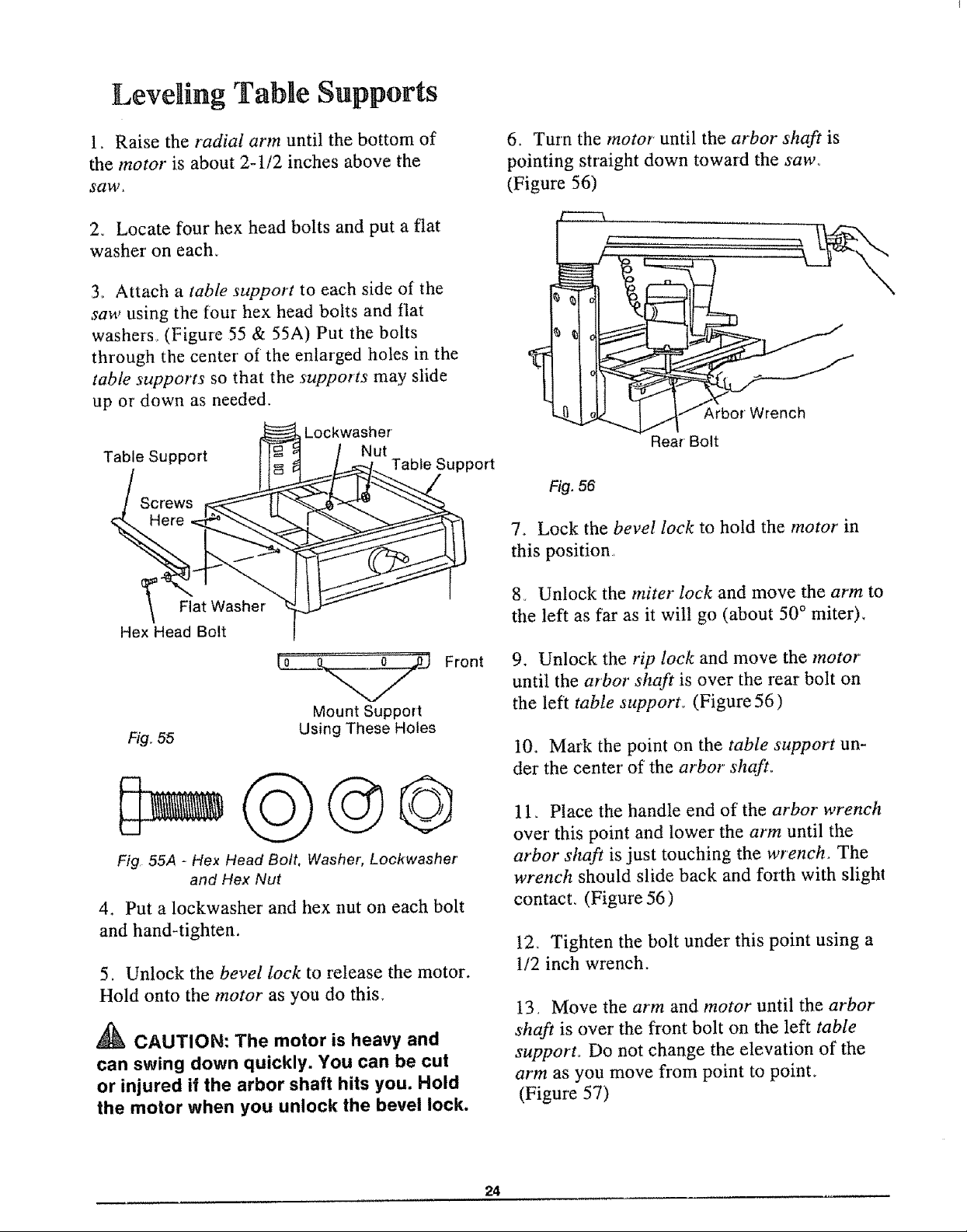
1. Loosen the four screws in the front of the
cohmm support. (Figure 53)
These adjustments must be done in order,
before using your saw for the first time. If
they are not done in order' the saw will not
cut accurately. If you miss an adjustment, you
must go back to the adjustment you missed
and repeat all steps from that point on.
These adjustments are like fine tuning a
piece of equipment. Often a series of steps
must be repeated more than once in order to
get the adjustment just right.
gk _
_WARNINL_: Plugging the saw in
during alignment can result in electrical
shock or your fingers, hand, or arm
being cut off from blade contact. Do not
plug in the saw at any time during align-
ment. The saw should only be plugged
in when it is to be used.
Make sure that the blade and blade guard are
removed from the arbor shaft before begin-
ning to align your saw. Do not install the
blade or blade guard until you are instructed
to do so.
Four Socket
Head Screws
Fig,,53
2. Raise and lower the radial arm by turning
the handwheeI a few turns in each direction.
It should take about the same amount of ef-
fort to lower the arm as to raise it.
3oIf movement seems smooth and the
column does not rock back and forth, go to
the next section, or
If movement seems difficult, loosen the four
bolts in the back of the cohmm slightly
(Figure 54) and go back to step 2, or
If column rocks back and forth, tighten the
four bolts in the back of the cohtmn slightly
(Figure 54) and go back to step 2.
Adjusting Elevation
The goal of this adjustment is to make up-
ward and downward movement of the radial
arm smooth and firm. If the column that sup-
ports the arm is too tight it will be difficult to
move the arm up and down and to get ac-
curate depth of cut. If the column is loose the
blade may "walk" on the workpiece and stall
the motor, or cause a heel in bevel and com-
pound cuts.
ooot
23
Leveling Table Supports
1o Raise the radial arm until the bottom of
the motor is about 2-1/2 inches above the
saw,
2. Locate four hex head bolts and put a flat
washer on each_
3, Attach a table support to each side of the
saw using the four hex head bolts and flat
washers, (Figure 55 & 55A) Put the bolts
through the center of the enlarged holes in the
table supports so that the supports may slide
up or down as needed.
Lockwasher
Table Support
Screws
Here
Nut
Table Support
6. Turn the motor' until the arbor shaft is
pointing straight down toward the saw°
(Figure 56)
£
Arbor Wrench
Rear Bolt
Fig. 56
74 Lock the bevel lock to hold the motor in
this position,
_" Flat Washer
Hex Head Bolt
(0 (L _ Front
Mount Support
Fig. 55
Fig 55A - Hex Head Bolt, Washer; Lockwasher
and Hex Nut
Using These Holes
4. Put a lockwasher and hex nut on each bolt
and hand-tighten.
5_ Unlock the bevel lock to release the motor.
Hold onto the motor as you do this.
A'k
CAUTION: The motor is heavy and
can swing down quickly. You can be cut
or injured if the arbor shaft hits you. Hold
the motor when you unlock the bevel lock.
8_ Unlock the miter lock and move the arm to
the left as far as it will go (about 50° miter).
9. Unlock the rip lock and move the motor
until the arbor shaft is over the rear bolt on
the left table support. (Figure 56)
I0. Mark the point on the table support un-
der the center of the arbor shaft,,
11. Place the handle end of the arbor wrench
over this point and lower the arm until the
arbor shaft is just touching the wrench. The
wrench should slide back and forth with slight
contact_ (Figure 56)
12_ Tighten the bolt under this point using a
1/2 inch wrench.
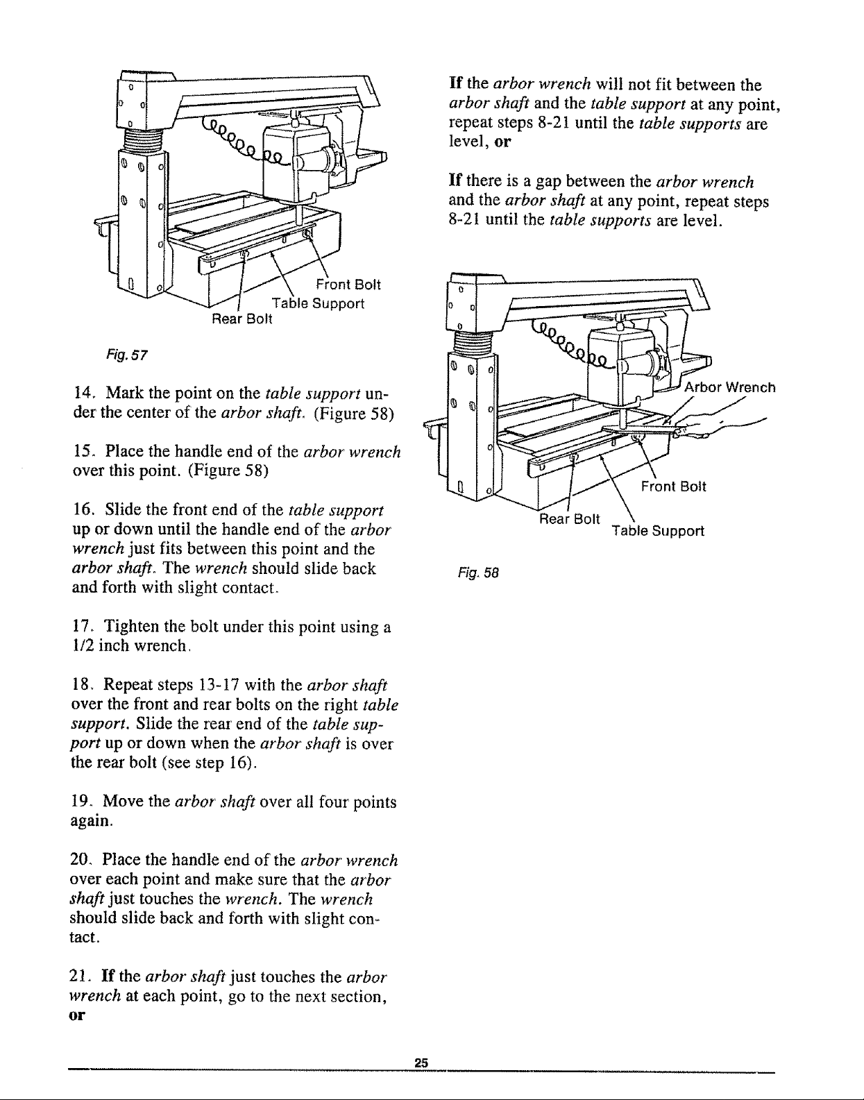
t3, Move the arm and motor until the arbor
shaft is over the front bolt on the left table
support° Do not change the elevation of the
arm as you move from point to poinL
(Figure 57)
24
Rear Bolt
If the arbor wrench will not fit between the
arbor shaft and the table support at any point,
repeat steps 8-21 until the table supports are
level, or
If there is a gap between the arbor wrench
and the arbor shaft at any point, repeat steps
8-2t until the table supports are level.
Front Bolt
Table Support
Fig. 57
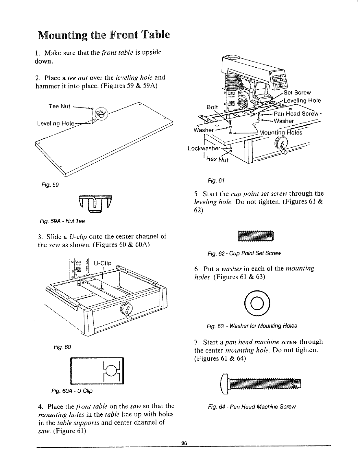
14. Mark the point on the table support un-
der the center of the arbor shaft° (Figure 58)
15_ Place the handle end of the arbor wrench
over this point. (Figure 58)
16. Slide the front end of the table support
up or down until the handle end of the arbor
wrench just fits between this point and the
arbor shaft. The wrench should slide back
and forth with slight contacL
17_ Tighten the bolt under this point using a
1/2 inch wrench,
184 Repeat steps 13-17 with the arbor shaft
over the front and rear bolts on the right table
support. Slide the rear end of the table sup-
port up or down when the arbor shaft is over
the rear bolt (see step 16).
t I
r Wrench
Front Bolt
Rear Bolt
Table Support
Fig_58
19. Move the arbor shaft over all four points
again.
20. Place the handle end of the arbor wrench
over each point and make sure that the arbor
shaft just touches the wrench. The wrench
should slide back and forth with slight con-
tact.
21. If the arbor shaft just touches the arbor
wrench at each point, go to the next section,
or
25
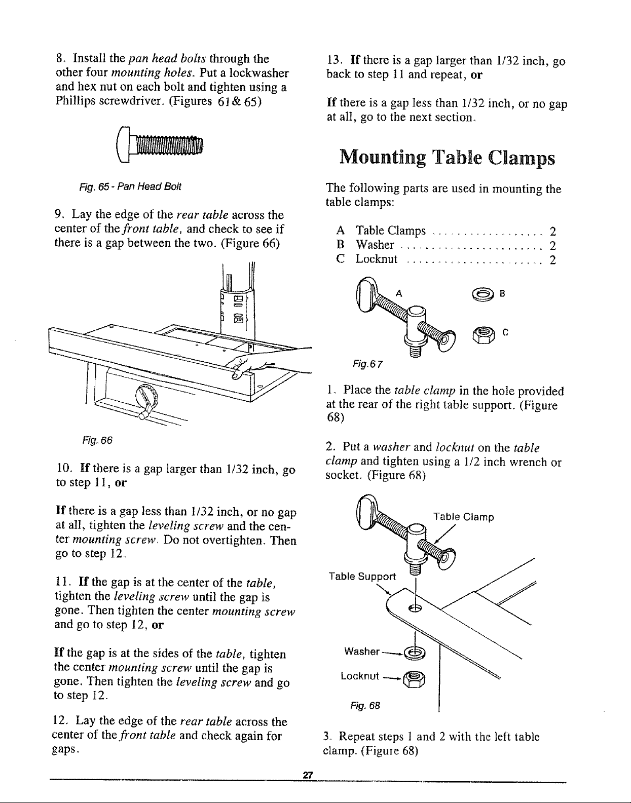
Mounting the Front Table
1_ Make sure that thefi"ont table is upside
down.
2_ Place a tee nut over' the leveling hole and
hammer it into place_ (Figures 59 & 59A)
Tee Nut ---..,-_, ._,)
Fig..59
rNv
Fig, 59A - Nut Tee
3.. Slide a U-clip onto the center channel of
the saw as shown, (Figures 60 & 60A)
U-Clip
Bolt
Fig,,61
5. Start the cup point set screw through the
leveling hole. Do not tighten. (Figures 61 &
62)
Fig_62 - Cup Point Set Screw
& Put a washer in each of the mounting
hotes_ (Figures 61 & 63)
Fig. 60
Fig. 60A- U Clip
4. Place the fi'ont table on the saw so that the
mounting holes in the table line up with holes
in the table supports and center' channel of
saw. (Figure 61)
Q
Fig,,63 - Washer for Mounting Holes
7,. Start a pan head machine screw through
the center mounting hole Do not tighten.
(Figures 61 & 64)
Fig° 64 - Pan Head Machine Screw
26
8. Install the pan head bolts through the
other four mounting holes, Put a tockwasher
and hex nut on each bolt and tighten using a
Phillips screwdriver_ (Figures 6] & 65)
13. If there is a gap larger' than 1/32 inch, go
back to step 11 and repeat, or
If there is a gap less than 1/32 inch, or no gap
at all, go to the next section.
Mounting TabLe Clamps
Fig. 65- Pan Head Bolt
9. Lay the edge of the rear table across the
center of the front table, and check to see if
there is a gap between the two. (Figure 66)
Fig°66
10. If there is a gap larger than 1/32 inch, go
to step 1t, or
The following parts are used in mounting the
table clamps:
A Table Clamps .................... 2
B Washer ......................... 2
C Locknut ......................... 2
®°
Fig,67
1. Place the table clamp in the hole provided
at the rear of the right table support. (Figure
68)
2. Put a washer and locknut on the table
clamp and tighten using a 1/2 inch wrench or
socket° (Figure 68)
If there is a gap less than 1/32 inch, or no gap
at all, tighten the leveling screw and the cen-
ter mounting screw, Do not overtighten. Then
go to step 12o
1I. If the gap is at the center of the table,
tighten the leveling screw until the gap is
gone. Then tighten the center mounting screw
and go to step 12, or
If the gap is at the sides of the table, tighten
the center mounting screw until the gap is
gone. Then tighten the leveling screw and go
to step t2.
12. Lay the edge of the rear table across the
center' of the front table and check again for
gaps.
Table_e Clamp
3. Repeat steps 1 and 2 with the left table
clamp° (Figure 68)
27
Squaring Crosscut Travel
The blade must travel perpendicular to the
fence along the radial arm in order for cross-
cuts to be accurate. If the radial arm is not
perpendicular to the fence, there will be a
slight miter angle in all crosscuts.
_ WARNING: Plugging in the saw dur-
ing alignment can result in your fingers,
hands, or arm being cut off from blade
contact. Do not plug in the saw at any
time during alignment. The saw should
only be plugged in when it is to be used.
CAUTION: Overtightening the arbor
nuts may cause the blade collars to
warp and the blade to wobble while cut-
ting. Use the arbor wrenches to tighten
the arbor nuts but do not overtighten.
4,, Unlock the rip lock and move the motor
until the blade is over the fi'ont table.
5o Lock the r'ip lock, miter lock and bevel
lock_
6_ Lower the radial arm until the blade is
just above the fi"ont table.
1. Place the radial arm in the 0° miter posi-
tion and lock the miter lock.
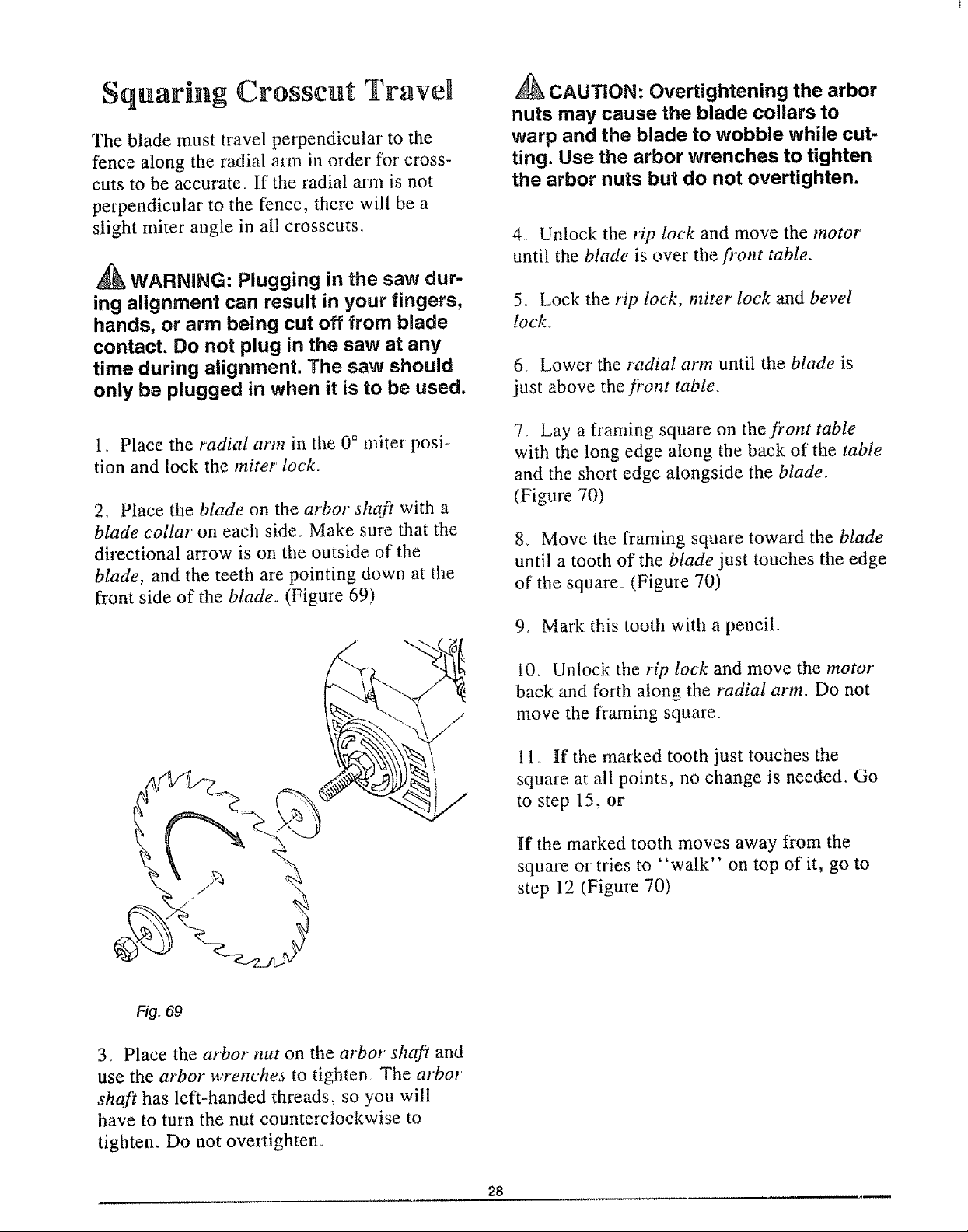
2_ Place the blade on the ar'bor shaft with a
blade collar on each side. Make sure that the
directional arrow is on the outside of the
blade, and the teeth are pointing down at the
front side of the blade. (Figure 69)
7.. Lay a f?aming square on thefiont table
with the long edge along the back of the table
and the short edge alongside the blade.
(Figure 70)
8. Move the framing square toward the blade
until a tooth of the blade just touches the edge
of the square. (Figure 70)
9. Mark this tooth with a pencil.
10b Unlock the rip lock and move tile motor
back and forth along the radial arm. Do not
move the framing square.
t 1_. If the marked tooth just touches the
square at all points, no change is needed. Go
to step 15, or
If the marked tooth moves away fl'om the
square or tries to "walk" on top of it, go to
step 12 (Figure 70)
Fig. 69
3., Place the arbor nut on the arbor shaft and
use the arbor wrenches to tighten. The arbor'
shaft has left-handed threads, so you will
have to turn the nut counterclockwise to
tightem Do not overtighten.
28
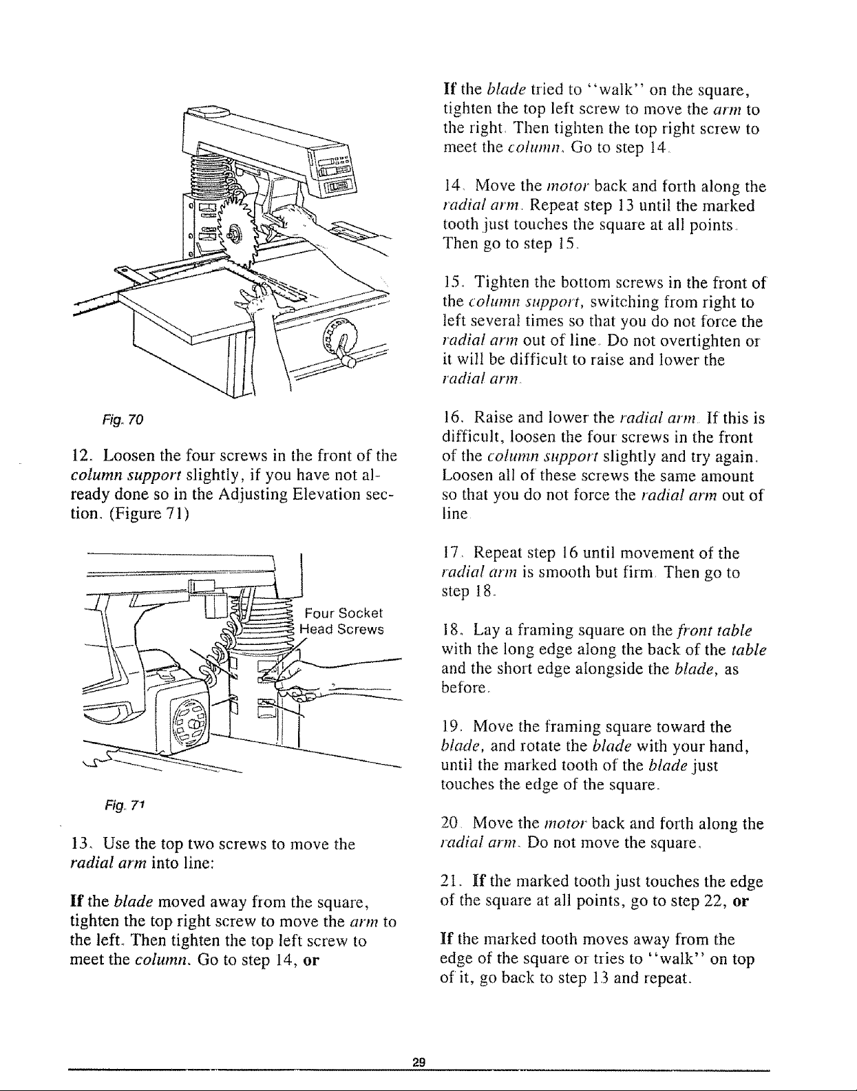
If the blade tried to "walk" on the square,
tighten the top left screw to move the aHn to
the right+ Then tighten the top right screw to
meet the column_ Go to step 14
t4, Move the motor back and forth along the
radial arm. Repeat step 13 until the marked
tooth just touches the square at all points _
Then go to step 15+
15+ Tighten the bottom screws in the front of
the column support, switching from right to
left several times so that you do not force the
radial arm out of line. Do not overtighten or
it will be difficult to raise and lower the
r'adial arm.
Fi9o70
12. Loosen the four screws in the front of the
column support slightly, if you have not al-
ready done so in the Adjusting Elevation sec-
tion. (Figure 71)
Four Socket
Head Screws
Fig,, 7"1
13, Use the top two screws to move the
radial arm into line:
It' the blade moved away from the square,
tighten the top right screw to move the arm to
the left+ Then tighten the top left screw to
meet the column. Go to step 14, or
16,. Raise and lower' the radial arm If this is
difficult, loosen the four screws in the front
of the cohmm support slightly and try again+
Loosen all of these screws the same amount
so that you do not force the r'adial arm out of
line
17. Repeat step 16 until movement of the
radiat arm is smooth but firm Then go to
step t 8
18o Lay a framing square on the front table
with the long edge along the back of the table
and the short edge alongside the blade, as
bef0re_
19_ Move the framing square toward the
blade, and rotate the blade with your hand,
until the marked tooth of the blade .just
touches the edge of the square.
20 Move the motor back and forth along the
radial arm. Do not move the square,
21+ If the marked tooth .just touches the edge
of the square at all points, go to step 22, or
If the mmked tooth moves away from the
edge of the square or+tries to "walk" on top
of it, go back to step 13 and repeat.
29
22° Lock the rip lock, put the spacer, fence
and rear table back in place, lock the table
clamp, and go to the next section.
Squaring Blade to Table
for Crosscutting
These steps are necessary so that your blade
will be perpendicular to the table and cuts
will be accurate_ If this is not done correctly,
your cuts will have a slight bevel angle.
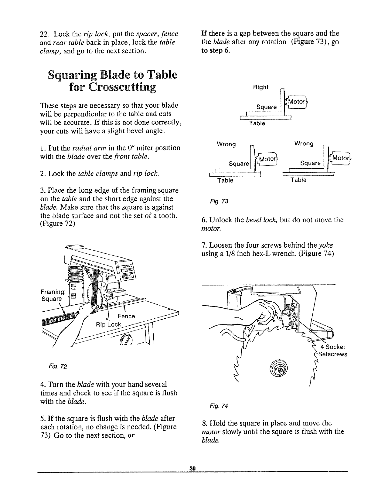
If there is a gap between the square and the
the blade after any rotation (Figure 73), go
to step 6.
Right
t i Square j_
Table
1. Put the radial arm in the 0° miter position
with the blade over the front table_
2o Lock the table clamps and rip lock.
3. Place the long edge of the framing square
on the table and the short edge against the
blade. Make sure that the square is against
the blade surface and not the set of a tooth.
(Figure 72)
Framing
Square
Wrong _ j_____ Wrong I-]"
Square[ _ Square [_
Table Table
Fig. 73
6. Unlock the bevel lock, but do not move the
motor.
7. Loosen the four screws behind the yoke
using a 1/8 inch hex-L wrench. (Figme 74)
FI#. 72
4. Turn the blade with your hand several
times and check to see if the square is flush
with the blade.
5. If the square is flush with the blade after
each rotation, no change is needed. (Figure
73) Go to the next section, or
1 __Setscrews
f- ® /I
Fig. 74
8. Hold the square in place and move the
motor slowly until the square is flush with the
blade.
30
 Loading...