

Craftsman 113198210 Owner’s Manual
Save This Manual
For Future Reference
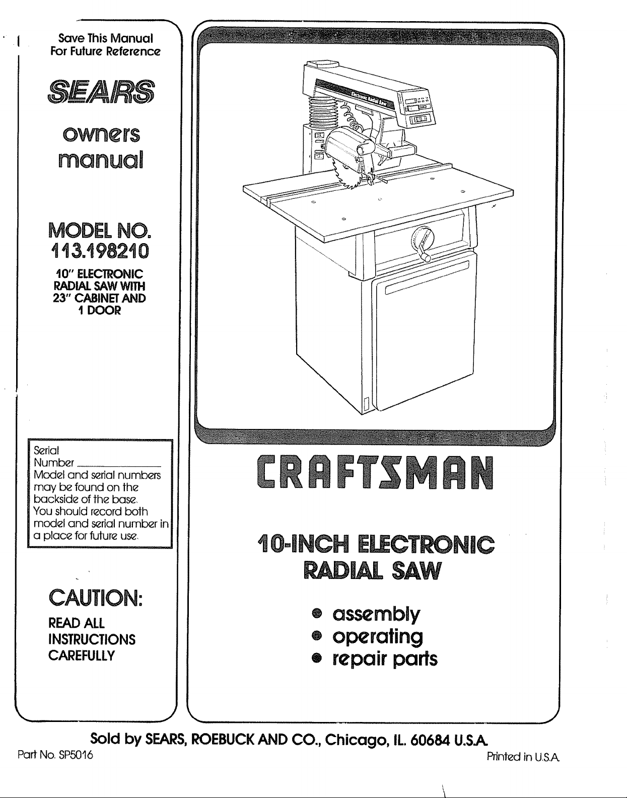
I 0" ELECTRONIC
RADIALSAWWITH
23" CABINETAND
1 DOOR
S_rial
Number ...........
Model and s_rial numbers
may b_ found on the
backside of the base
You should record both
model and s_rial number in
a place for future us_,
I
CAUTION:
READALL
INSTRUCTIONS
CAREFULLY
Sold by SEARS,ROEBUCKAND CO., Chicago, IL 60684 U.S.A.
Part No, SP5016 Printed in US.A.
® assembly
® operating
• repair parts
FULL ONE YEAR WARRANTY ON CRAFTSMAN RADIAL SAW
If within one year from the date of purchase, this Craftsman Radial Saw fails due to a defect tn material or
workmanship,Sears will repair It, free of charge,,
WARRANTY SERVICE IS AVAILABLE BY SIMPLY CONTACTING THE NEAREST SEARS SERVICE
CENTER/DEPARTMENT THROUGHOUT THE UNITED STATES
This warranty appIies onty while this product 18used in the United Staten°
ThlBwarranty gives you specificlegal rights,and you may also have other rights which vary from stateto 0late,
SEARS, ROEBUCK AND CO,,,DEPTo698/731A Sears Tower, Chicago, IL 60684
GENERAL SAFETY iNSTRUCTiONS FOR POWER TOOLS
1. KNOW YOUR POWER TOOL
Read and .understand the owner's manual and
labels affixed to the tool Learn its application
and limitations as weti as the specific potential
hazards peculiar to this loci
2o GROUND ALL TOOLS
This toot is equipped with an approved
3-conductor cord and a 3~prong grounding
type plug to fit the proper grounding type
receptacle The green conductor in the cord is
the grounding wire Never connect the green
wire to a live termina]
3. KEEP GUARDS IN PLACE,
in working order, and in proper adjustment and
alignment
4_ REMOVE ADJUSTING KEYS
AND WRENCHES
Form habit of checking to see that keys and
adjusting wrenches are removed from tool
before turning it on
5,, KEEP WORK AREA CLEAN
Cl_uttered areas and benches invite accidents
Floor must not be slippery due to wax or
sawdust
6, AVOID DANGEROUS ENVIRONMENT
Don't use power tools in damp or wet locations
or expose them to rain Keep work area wel!
lighted Provide adequate surrounding work
space
7o KEEP CHILDREN AWAY
AH visitors should be kept a safe distance from
work area
8. MAKE WORKSHOP CHILD-PROOF
with padlocks master switches, or by
removing starter keys
9. DON'T FORCE TOOL
It wilf do the job better and safer at the rate for
which it was designed
10. USE RIGHT TOOL
Don't force tool or attachment to do a job it was
not designed for
11_ WEAR PROPER APPAREL
Do not wear Goose clothing, gloves, neckties or
jewelry (rings, wrist watches) to get caught in
moving parts Nonslip footwear is
recommended Wear protective hair covering to
contain long hair Roll long sleeves above the
efbow
12_ USE SAFETY GOGGLES (Head Protection)
Wear Safety goggles (must comply with ANSI
Z871) at art times Everyday eyeglasses only
have impact resistant lenses, they are NOT
safety glasses. Also, use face or dust mask if
cutting operation is dusty, and ear protectors
(plugs or muffs) during extended periods of
operation
13o SECURE WORK
Use clamps or a vise to hold work when
practical It's safer than using your hand, frees
both hands to operate tool
14_ DON'T OVERREACH
Keep proper footing and balance at all times
15, MAINTAIN TOOLS WITH CARE
Keep tools sharp and clean for best and safest,
performances Follow instructions for
lubricating and changing accessories
16. DISCONNECT TOOLS
before servicing; when changing accessories
such as blades, bits., cutters, etc
17,, AVOID ACCIDENTAL STARTING
Make sure switch is in 'OFF" position before
plugging in
18, USE RECOMMENDED ACCESSORIES
Consult the owner's manual for recommended
accessories Follow the instructions that
accompany the accessories The use of
improper accessories may cause hazards
19. NEVER STAND ON TOOL
Serious injury could occur if the tool is tipped or
if the cutting tool is accidentally contacted
Do not store materials above or near the tool
such that it is necessary to stand on the tool to
reach them
20, CHECK DAMAGED PARTS
Before further use of the tool a guard or other
part that is damaged should be carefully
checked to ensure that it will operate properly
and perform its intended function Check fo_
alignment of moving parts, binding of moving
parts, breakage of parts, mounting, and any
other conditions that may effect its operation. A
guard or other part that is damaged should be
properly repaired or replaced
21o DIRECTION OF FEED
Feed work into a blade or cutter against the
direction of rotation of the blade or cutter only
22° NEVER LEAVE TOOL RUNNING
UNATTENDED
Turn power off Don't leave tool until it comes to
a complete stop
additionaU
BEFORE USING THE SAW:
instructions for radiaUsaws
t'¢= L--
OO*-,
GO
m
WARNING: TO AVOID MISTAKES THAT COULD
RESULT IN SERIOUS, PERMANENT INJURY, DO
NOT CONNECT POWER CORD UNTIL THE FOL-
LOWING STEPS HAVE BEEN SATISFACTORILY
COMPLETED:
1. Assembly and alignment.. (See pages 15-24.)
2.. Examination and operating familiarity with ON-
OFF switch, elevation hand wheel, swivel lock,
bevel lock and rip lock, guard clamp screw,
spreader and anti-kickback device and miter
lock. (See pages 30, 31 & 32.)
3. Review and understanding of all safety instruc-
tions and operating procedures throughout the
manual
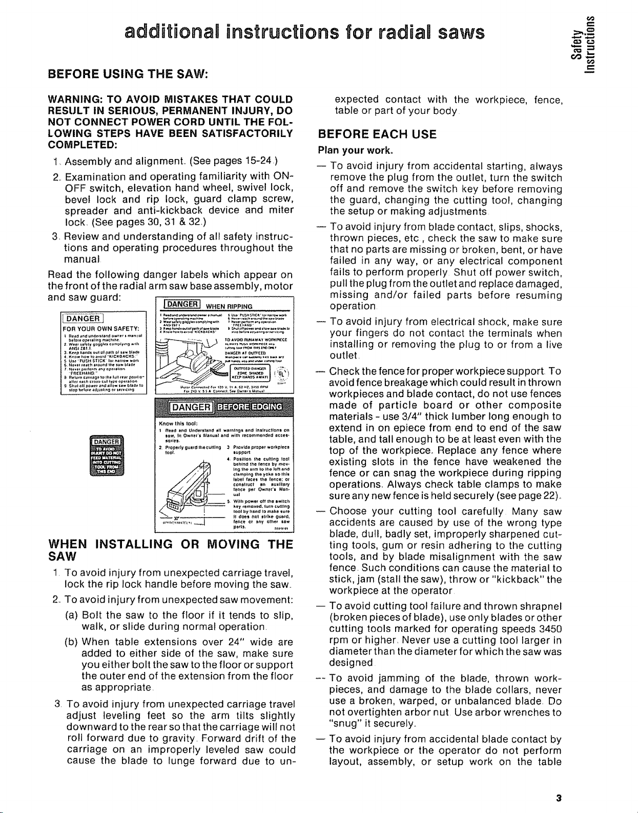
Read the following danger labels which appear on
the front of the radial arm saw base assembly, motor
and saw guard:
FOR YOUR OWN SAFETY:
WHEN RIPPING
WHEN INSTALLING OR MOVING THE
SAW
1. To avoid injury from unexpected carriage travel,
lock the rip lock handle before moving the saw..
2..To avoid injury from unexpected saw movement:
(a) Bolt the saw to the floor if it tends to slip,
walk, or slide during normal operation.
(b) When table extensions over 24" wide are
added to either side of the saw, make sure
you either bolt the saw to the floor or support
the outer end of the extension from the floor
as appropriate.
3. To avoid injury from unexpected carriage travel
adjust leveling feet so the arm tilts slightly
downward to the rear so that the carriage will not
roll forward due to gravity. Forward drift of the
carriage on an improperly leveled saw could
cause the blade to lunge forward due to un-
expected contact with the workpiece, fence,
table or part of your body
BEFORE EACH USE
Plan your work,
-- To avoid injury from accidental starting, always
remove the plug from the outlet, turn the switch
off and remove the switch key before removing
the guard, changing the cutting tool, changing
the setup or making adjustments
To avoid injury from blade contact, slips, shocks,
thrown pieces, etc, check the saw to make sure
that no parts are missing or broken, bent, or have
failed in any way, or any electrical component
fails to perform properly Shut off power switch,
pull the plug from the outlet and replace damaged,
missing and/or failed parts before resuming
operation
To avoid injury from electrical shock, make sure
your fingers do not contact the terminals when
installing or removing the plug to or from a live
outlet.
Check the fence for proper workpiece support. To
avoid fence breakage which could result in thrown
workpieces and blade contact, do not use fences
made of particle board or other composite
materials - use 3/4" thick lumber long enough to
extend in on epiece from end to end of the saw
table, and tall enough to be at least even with the
top of the workpiece. Replace any fence where
existing slots in the fence have weakened the
fence or can snag the workpiece during ripping
operations. Always check table clamps to make
sure any new fence is held securely (see page 22)_
Choose your cutting tool carefully Many saw
accidents are caused by use of the wrong type
blade, dull, badly set, improperly sharpened cut-
ting tools, gum or resin adhering to the cutting
tools, and by blade misalignment with the saw
fence. Such conditions can cause the material to
stick, jam (stall the saw), throw or "kickback" the
workpiece at the operator
-- To avoid cutting tool failure and thrown shrapnel
(broken pieces of blade), use only blades or other
cutting tools marked for operating speeds 3450
rpm or higher, Never use a cutting toot larger in
diameter than the diameter for which the saw was
designed
--To avoid jamming of the blade, thrown work-
pieces, and damage to the blade collars, never
use a broken, warped, or unbalanced blade. Do
not overtighten arbor nut Use arbor wrenches to
"snug" it securely°
To avoid injury from accidental blade contact by
the workpiece or the operator do not perform
layout, assembly, or setup work on the table
while thecuttingtool is rotating. Therotating
tool could cut and throw anythinghitting the
bladecaus{ngthe saw to unexpectedlycome
forward
Usetherightguard.Toavoidlosingcontrolofthe
workpiece,hittingthecuttingtool,orbeingstruck
bythrownpieces,neverdoanycuttingunlessthe
properguard(withallitspartsinplace)isinstalled
andadjustedproperly..
Toavoidinjuryfromthrownpieces,slips,blade
contact,orjammingoftheworkpiece,makesure
noplayexistsbetweenthe columnandcolumn
supportorin the carriage and that the arm, yoke,
bevel locks/clamps are tighL
To avoid injury from thrown objects, slips or
jamming of the blade due to pinching of the blade
by shifting boards:
(a) Do not leave a long board unsupported so the
spring of the board causes it to twist or rise
from the table
(b) Check to be sure that pieces will not fall off
the table once they have been cut.
(c) Provide support for the workpiece, based on
its size and the type of operation to be
performed
(d) Never use another person as a substitute fora
table extension, or as an additional support
for a workpiece to assist in feeding, support-
ing, or pulling the workpiece
(e) Never cut workpieces placed side to side or
stacked on top of each other The pieces can
slide on each other.
WEAR YOUR
of asecond is sufficient to inflict severe, permanent
injury
if your saw makes an unfamiliar noise or' if it
vibrates excessively, stop the operation immedi-
ately, Do not restart until the source has been
located and the problem corrected
-- Do not cycle the motor switch "ON" and "OFF"
rapidly, as this might cause the sawblade to
loosen. In the event this should ever occur, turn
the switch off, allow the sawblade to come to a
complete stop, and remove the switch key To
avoid damage to the blade and flange, retighten
the arbor nut normally, not excessively..
-- Never perform any operation freehand injury can
occur from blade contact or' thrown pieces when
the workpiece is torn from the hands.. "Freehand"
means feeding the sawblade into a workpiece or
feeding the workpiece into the sawblade or other
cutting tool without using the fence orsome other
proper device to prevent the workpiece from
twisting and binding on the cutting tool during the
cutting operat[on
To avoid accidental blade contact, avoid awkward
hand positions where a sudden slip causes a hand
to move toward the sawblade or other cutting
tool Do not place fingers or hand on the work-
piece or table that is in the path of the sawblade
To avoid injury from unexpected starting, never
attempt to free a stalled sawblade without first
turning the saw "OFF" and removing the switch
key If the sawblade isstatfed or' jammed, shut the
saw "OFF", remove the switch key, remove the
workpiece, check for' looseness in clamps, arm
and carriage, check the sawblade squareness to
the table surface and to the fence, and check for
heel (see page 22).. Adjust as indicated.
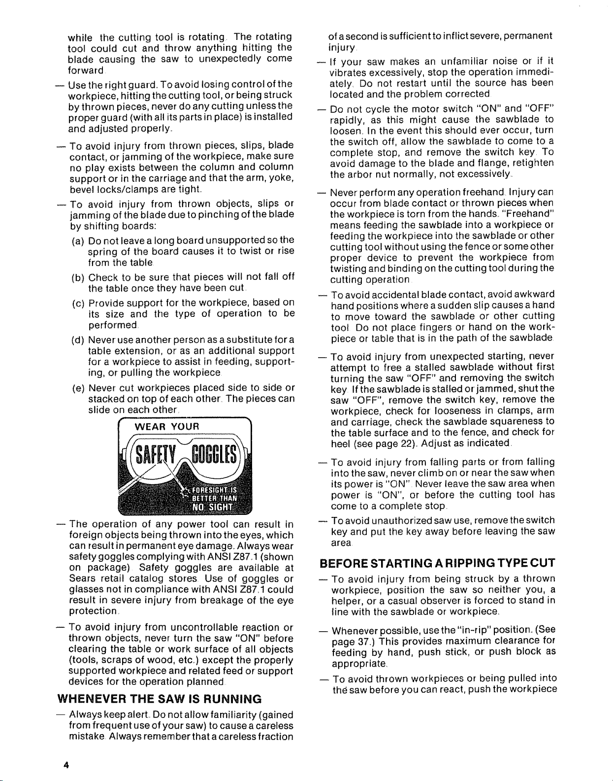
The operation of any power- tool can result in
foreign objects being thrown into the eyes, which
can result in permanent eye damage.. Always wear
safety goggles complying with ANSI Z87.1 (shown
on package) Safety goggles are available at
Sears retail catalog stores Use of goggles or
glasses not in compliance with ANSI Z87.1 could
result in severe injury from breakage of the eye
protection,
To avoid injury from uncontrollable reaction or
thrown objects, never turn the saw "ON" before
clearing the table or work surface of all objects
(tools, scraps of wood, etc..) except the properly
supported workpiece and related feed or support
devices for the operation planned
WHENEVER THE SAW IS RUNNING
-- Always keep alert. Do not allow familiarity (gained
from frequent use of your saw) to cause a careless
mistake. Always remember that a careless fraction
-- To avoid injury from falling parts or from falling
into the saw, never climb on or near the saw when
its power is "ON" Never leave the saw area when
power' is "ON", or before the cutting tool has
come to a complete stop.
To avoid unauthorized saw use, remove the switch
key and put the key away before leaving the saw
area
BEFORE STARTING A RIPPING TYPE CUT
To avoid injury from being struck by a thrown
workpiece, position the saw so neither you, a
helper', or a casual observer is forced to stand in
line with the sawbtade or workpiece.
-- Whenever possible, use the "in-rip" position_ (See
page 37_) This provides maximum clearance for
feeding by hand, push stick, or push block as
appropriate.
-- To avoid thrown workpieces or being pulled into
the saw before you can react, push the workpiece
4
fromthenoseside(oppositethesawdustexhaust
chute)of the guard.Notethe warningon the
guard..
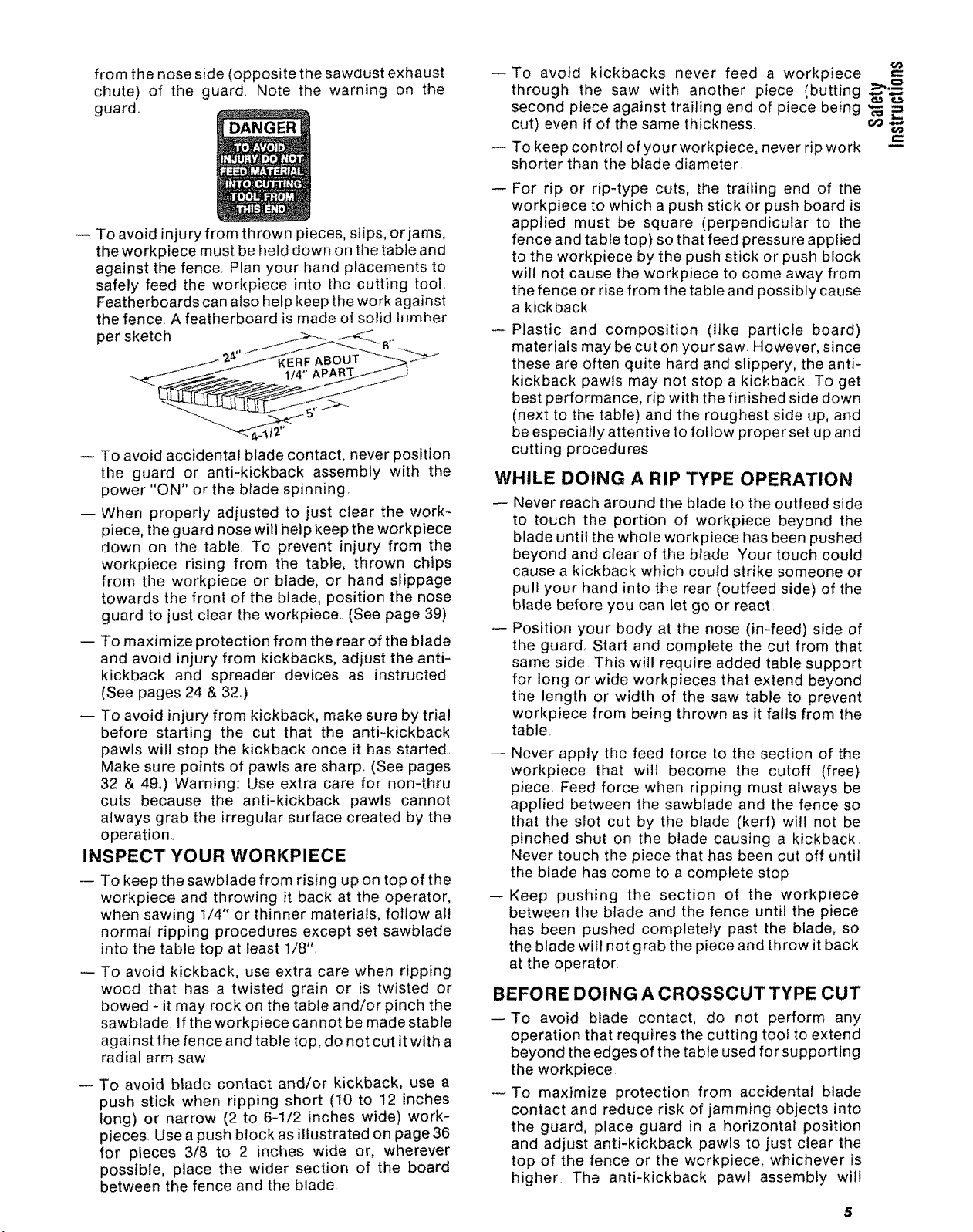
Toavoidinjuryfromthrownpieces,slips,orjams,
theworkpiecemustbehelddownonthetableand
againstthefence..Planyourhandplacementsto
safelyfeedtheworkpieceinto thecuttingtool.
Featherboardscanalsohelpkeeptheworkagainst
thefence.Afeatherboardismadeofsolidlumher
persketch !._-_--A__ _,.
Toavoidaccidentalbladecontact,neverposition
the guard or anti-kickbackassemblywith the
power"ON"orthebladespinning.
-- Whenproperlyadjustedto justclearthework-
piece,theguardnosewillhelpkeeptheworkpiece
downon thetable.To preventinjury fromthe
workpiecerisingfrom the table,thrown chips
fromthe workpieceor blade,or handslippage
towardsthefrontoftheblade,positionthenose
guardtojustcleartheworkpiece..(Seepage39)
-- Tomaximizeprotectionfromtherearoftheblade
andavoidinjuryfromkickbacks,adjusttheanti-
kickbackand spreaderdevicesas instructed.
(Seepages24&32.)
-- Toavoidinjuryfromkickback,makesurebytrial
beforestartingthe cut that the anti-kickback
pawlswill stopthekickbackonceit hasstarted..
Makesurepointsofpawlsaresharp,(Seepages
32& 49°)Warning:Useextracarefor nomthru
cuts becausethe anti-kickbackpawls cannot
alwaysgrabtheirregularsurfacecreatedbythe
operation.
INSPECT YOUR WORKPIECE
-- Tokeepthesawbladefromrisingupontopofthe
workpieceandthrowingit backattheoperator,
whensawing1/4"orthinnermaterials,followall
normalrippingproceduresexceptsetsawblade
intothetabletopatleast1/8",
Toavoidkickback,useextracarewhenripping
woodthat hasa twistedgrain or is twistedor
bowed-it mayrockonthetableand/orpinchthe
sawblade,Iftheworkpiececannotbemadestable
againstthefenceandtabletop,donotcutitwitha
radialarmsaw
To avoidbladecontactand/orkickback,usea
pushstickwhenrippingshort (10to 12inches
long)or narrow(2to 6-1/2incheswide)work-
pieces.Useapushblockasillustratedonpage36
for pieces3/8 to 2 incheswide or, wherever
possible,placethe widersectionof the board
betweenthefenceandtheblade.
To avoid kickbacks never feed a workpiece
through the saw with another piece (butting _'_-_
second piece against trailing end of piece being '_ =
cut) even if of the same thickness, c,_
To keep control of your workpiece, never rip work
shorter than the blade diameter
For rip or rip-type cuts, the trailing end of the
workpiece to which a push stick or push board is
applied must be square (perpendicular to the
fence and table top) so that feed pressure applied
to the workpiece by the push stick or push block
will not cause the workpiece to come away from
the fence or rise from the table and possibly cause
a kickback
Plastic and composition (like particle board)
materials may be cut on your saw. However, since
these are often quite hard and slippery, the anti-
kickback pawls may not stop a kickback To get
best performance, rip with the finished side down
(next to the table) and the roughest side up, and
be especially attentive to follow proper set up and
cutting procedures
WHILE DOING A RIP TYPE OPERATION
-- Never reach around the blade to the outfeed side
to touch the portion of workpiece beyond the
blade until the whole workpiece has been pushed
beyond and ctear of the blade Your touch could
cause a kickback which could strike someone or
pull your hand into the rear (outfeed side) of the
blade before you can let go or react
-- Position your body at the nose (in-feed) side of
the guard, Start and complete the cut from that
same side This will require added table support
for long or wide workpieces that extend beyond
the length or width of the saw table to prevent
workpiece from being thrown as it falls from the
table,,
Never apply the feed force to the section of the
workpiece that will become the cutoff (free)
piece. Feed force when ripping must always be
applied between the sawblade and the fence so
that the slot cut by the blade (kerf) will not be
pinched shut on the blade causing a kickback.
Never touch the piece that has been cut off until
the blade has come to a complete stop
--Keep pushing the section of the workpiece
between the blade and the fence until the piece
has been pushed completely past the blade, so
the blade wilt not grab the piece and throw it back
at the operator.
BEFORE DOING A CROSSCUT TYPE CUT
--To avoid blade contact, do not perform any
operation that requires the cutting tool to extend
beyond the edges of the table used for supporting
the workpiece
To maximize protection from accidental blade
contact and reduce risk of jamming objects into
the guard, place guard in a horizontal position
and adjust anti-kickback pawls to just clear the
top of the fence or the workpiece, whichever is
higher The anti-kickback pawl assembly will
5
6O
provide additional guarding from contact with the
front of the blade.
To prevent the cutting tool from grabbing the
table or workpiece and being propelled toward
you, never lower a revolving cutting tool into the
table or a workpiece without first locking the rip
lock handle and clamping the workpiece in place.
Release the handle only after having firmly
grasped the carriage handle.
To avoid blade contact or injury from a thrown cut
off piece, never use a length stop on the cut off
end or edge of the workpiece. Never hang onto or'
touch the cut off piece of the workpiece while the
power is "ON" and/or the sawblade is rotating To
prevent pinching that could cause the piece to be
thrown, the cut off piece must never be confined,
pushed, or grabbed while the blade is spinning.
INSPECT YOUR WORKPIECE
To avoid injury from thrown objects, slips or
jamming of the blade, make sure the workpiece
will fit the supports (fence, table, fixtures or jigs)
so it will not twist, rock or otherwise bind on the
cutting tool. Make sure there is no sawdust or
other foreign material between the workpiece and
its support.
WHILE DOING A CROSSCUT TYPE CUT
Always start with the carriage in the full rear
position behind the fence before turning the saw
On,
Never push the carriage and blade backwards
into the work to do a crosscutting type operation..
The cutting tool can throw the work over the
fence, striking someone or causing you to fall into
the blade.
Always return the carriage to the full rearward
position behind the fence at the completion of
each crosscut type operation Never remove your'
hand from the yoke handle unless the carriage is
in this position. Otherwise, the cutting tool may
climb up on the workpiece and be propelled
toward you.
BEFORE USING ACCESSORIES
To avoid injury from unanticipated hazards, use
only recommended accessories as listed on page
50°
The use of grinding wheels, abrasive or cut off
wheels, or wire wheels, can be dangerous and are
not recommended_ Such devices can break ex-
plosively and throw shrapnel, causing severe
injury
The sawblade, dado, or other cutting tool must be
removed from the saw arbor before using the
accessory shaft, Never operate the saw with
cutting tools (including sanding accessories or
buffing) installed on both ends of the saw arbor to
avoid being pulled into moving parts by hair,
threads, clothing, etc, Make sure the unused
arbor is always covered by aguard, the arm, or the
screw cap
Using a drill chuck, To avoid injury from sudden
bending or breaking of a drill bit, do not install or
use twist drills tonger than 7" in iength or extend-
ing more than 6" beyond the chuck jaws. Do not
instatl or use any reduced shank drill except the
opade type (1" diameter' or smaller).. Use for
drilling wood or plastic only - bit speed cannot be
properly adjusted for other materiafs. Do not use
twist drills larger than 1/2" in diameter
glossary of terms for woodworking
Anti-Kickback Pawls (AKB)
Device which, when properly adjusted, is designed
to stop the workpiece from being kicked back at the
operator during ripping operations. See illustrations
on pages 24 & 32.
Arbor
The shaft on which a cutting tool is mounted,
Crosscut
A cutting or shaping operation made across the
width of the workpiece_ See illustrations on pages
33-35
Dado
A non-through cut which produces a square sided
notch or' trough in the workpieceo
Featherboard
A device which can assist in guiding workpieces
during rip type operations.
Freehand
Performing a cut without the use of fence (guide),
hold down or other proper device to prevent the
workpiece from twisting during the cutting opera-
tion. Twisting of the workpiece can cause it to be
thrown or kicked back by a radial saw
Gum
A sticky, sap based residue from wood products..
Heel
Misalignment of the blade. See page 22
In-Rip
Positioning the blade parallel to the fence with the
motor toward the front of the saw_See illustration on
page 37_
Kerf
The amount of material removed by the blade in a
through cut or the slot produced by the blade in a
non-through or' partial cut
Kickback
An uncontrolled grabbing arid throwing of the work-
piece back toward the operator during a rip type
operation
Leading End
The end of the workpiece which, during a rip type
operation, is pushed into the cutting tool first
Molding
A non-through cut which produces a special shape
in the workpiece used for joining or decoration
Outrip
Positioningthebladeparallelto thefencewiththe
motortowardthe rearofthesawproducingmaxi-
mumrippingcapacity_Seeillustrationonpage37,
Push Stick
A device used to feed the workpiece through the saw
during narrow ripping type operations so the oper-
ator's hands are kept well away from the blade, See
page 36,
Push Block
A device used for ripping type operations too narrow
to allow use of a push stick_ See page 36.
Rabbet
A notch in the edge of a workpiece.
Resin
A sticky, sap base substance that has hardened,
Ripping
A cutting operation along the length of the work-
piece,
Revolutions Per Minute (RPM)
The number of turns completed by a spinning object
in one minute,
Sawblade Path
The area of the workpiece or table top directly in line
with either the travel of the blade or the part of the
workpiece which will be, or has been, cut by the
blade,
Set
The distance that the tip of the sawblade tooth is so
bent (or set) outward from the face of the blade, .3 "_,
Throw-Back .-
Throwing of small pieces in a manner similar to a _ =
kickback, _.u (=
Thru-Sawing
Any cutting operation where the blade extends
completely through the thickness of the workpiece,
Trailing End
The workpiece end last cut by the blade in a ripping
operation
Workpiece
The item on which the cutting operation is being
performed The surfaces of a workpiece are com-
monly referred to as faces, ends, and edges,
m
electrical connections
POWER SUPPLY
1. Motor Specifications
The A-C motor used in this saw is a capacitor-start,
non-reversible type having the following specifica-
tions:
Rated HoP....................................... 1.5
Maximum Developed H,P ........................ 25
Voltage ........................................ 120
Amperes ...................................... 11
Hertz (cycles) .................................. 60
Phase ........................................ Single
RPM ....................................... 3450
Rotation of Blade Arbor ................ Clockwise
WARNING: TO AVOID ELECTRICAL HAZARDS,
FIRE HAZARDS, OR DAMAGE TO THE TOOL, USE
PROPER CIRCUIT PROTECTION. YOUR SAW IS
WIRED ATTHE FACTORY FOR 120V OPERATION.
CONNECT TO A 120V, 15-AMP, BRANCH CIRCUIT
AND USE A 15-AMP, TIME DELAY FUSE OR
CIRCUIT BREAKER.
IF NOT PROPERLY GROUNDED THIS POWER
TOOL CAN CAUSE ELECTRICAL SHOCK -
PARTICULARLY WHEN USED IN DAMP LOCA-
TIONS IN PROXIMITY TO PLUMBING. IF AN
ELECTRICAL SHOCK OCCURS THERE IS ALSO
THE POTENTIAL OF A SECONDARY HAZARD
SUCH AS YOUR HANDS CONTACTING THE
SAWBLADE. NOT ALL OUTLETS ARE PROPERLY
GROUNDED. TO AVOID SHOCK OR FIRE, IF
POWER CORD tS WORN OR CUT, OR DAMAGED
tN ANY WAY, HAVE IT REPLACED IMMEDIATELY.
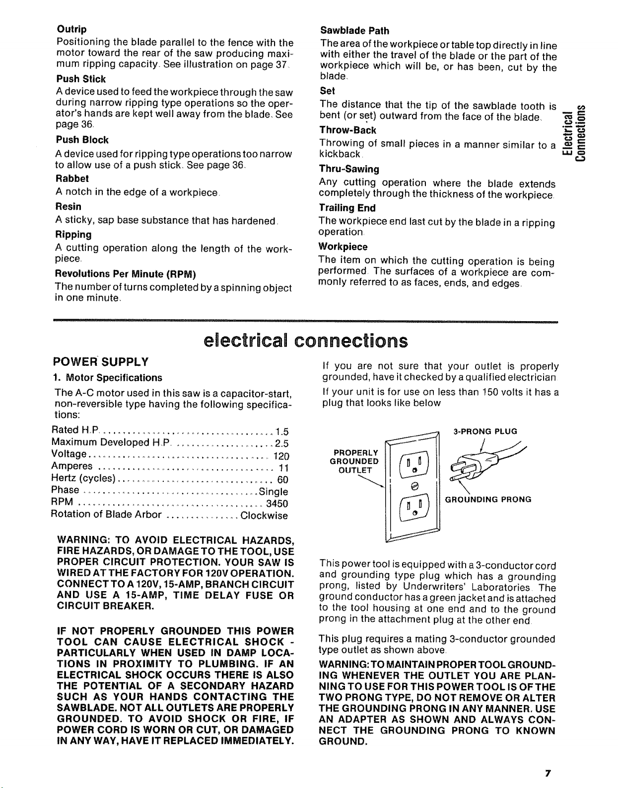
If you are not sure that your outlet is properly
grounded, have it checked by a qualified electrician
If your unit is for use on less than 150 volts it has a
plug that looks like below
3-PRONG PLUG
PROPERLY
GROUNDED
OUTLET
GROUNDING PRONG
This power tool is equipped with a 3-conductor cord
and grounding type plug which has a grounding
prong, listed by Underwriters' Laboratories The
ground conductor has agreen jacket and is attached
to the tool housing at one end and to the ground
prong in the attachment plug at the other end
This plug requires a mating 3-conductor grounded
type outlet as shown above
WARNING: TO MAINTAIN PROPER TOOL GROUND-
ING WHENEVER THE OUTLET YOU ARE PLAN-
NING TO USE FOR THIS POWER TOOL IS OFTHE
TWO PRONG TYPE, DO NOT REMOVE OR ALTER
THE GROUNDING PRONG IN ANY MANNER. USE
AN ADAPTER AS SHOWN AND ALWAYS CON-
NECT THE GROUNDING PRONG TO KNOWN
GROUND.
Itisrecommendedthatyouhaveaqualifiedelectri-
cian replacethetwoprongoutlet witha properly
groundedthreeprongoutlet,
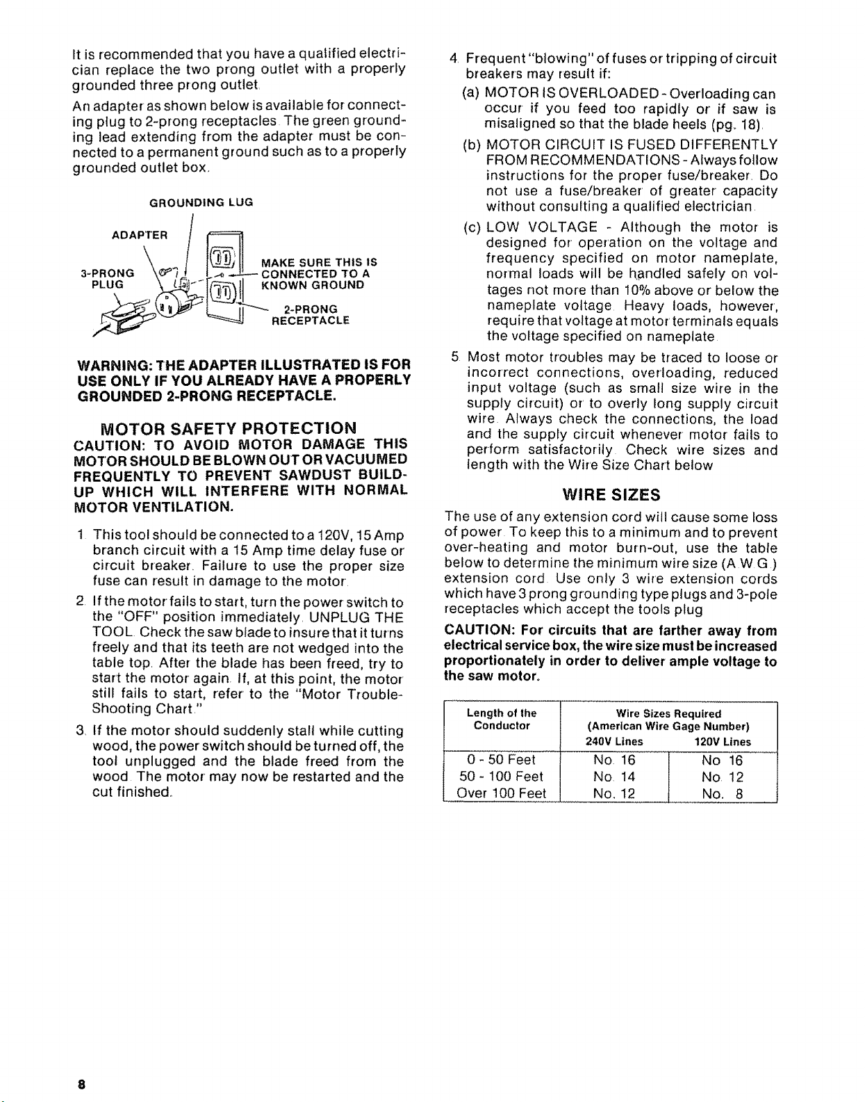
Anadapterasshownbelowisavailableforconnect-
ingplugto2-prongreceptaclesThegreenground-
ing leadextendingfromthe adaptermustbecon-
nectedtoapermanentgroundsuchastoaproperly
groundedoutletbox.
GROUNDING LUG
ADAPTER / I_..___.
3-PRONG "_! i CONNECTEDTOA
PLUG _- r[_ {t,_ .... NOWN GROUND
WARNING: THE ADAPTER ILLUSTRATED IS FOR
USE ONLY IF YOU ALREADY HAVE A PROPERLY
GROUNDED 2-PRONG RECEPTACLE.
CAUTION: TO AVOID MOTOR DAMAGE THIS
MOTOR SHOULD BE BLOWN OUT OR VACUUMED
FREQUENTLY TO PREVENT SAWDUST BUILD-
UP WHICH WILL INTERFERE WITH NORMAL
MOTOR VENTILATION.
1 This tool should be connected to a t20V, 15 Amp
branch circuit with a 15 Amp time delay fuse or'
circuit breaker. Failure to use the proper size
fuse can result in damage to the motor.
2. If the motor fails to start, turn the power switch to
the "OFF" position immediately. UNPLUG THE
TOOL. Check the saw blade to insure that it turns
freely and that its teeth are not wedged into the
table top. After the blade has been freed, try to
start the motor' again. If, at this point, the motor'
still fails to start, refer to the "Motor Trouble-
Shooting Chart?'
3. If the motor should suddenly stall while cutting
wood, the power switch should be turned off, the
toot unplugged and the blade freed from the
wood The motor' may now be restarted and the
cut finished.
_ MAKE SURE THIS IS
RECEPTACLE
MOTOR SAFETY PROTECTION
4. Frequent "blowing" of fuses or tripping of circuit
breakers may result if:
(a) MOTOR IS OVERLOADED - Overloading can
occur-if you feed too rapidly or' if saw is
misaligned so that the blade heels (pg_ 18).
(b) MOTOR CIRCUIT IS FUSED DIFFERENTLY
FROM RECOMMENDATIONS- Always follow
instructions for the proper fuse/breaker. Do
not use a fuse/breaker of greater capacity
without consuFting a qualified electrician.
(c) LOW VOLTAGE - Although the motor is
designed for operation on the voltage and
frequency specified on motor nameplate,
normal loads will be handled safely on vol-
tages not more than 10% above or below the
nameplate voltage Heavy loads, however,
require that voltage at motor terminals equals
the voltage specified on nameplate
5 Most motor troubles may be traced to loose or
incorrect connections, overloading, reduced
input voltage (such as small size wire in the
supply circuit) or to overly long supply circuit
wire Always check the connections, the load
and the supply circuit whenever motor fails to
perform satisfactorily Check wire sizes and
length with the Wire Size Chart below
WIRE SIZES
The use of any extension cord will cause some loss
of power To keep this to a minimum and to prevent
over-heating and motor burn-out, use the table
below to determine the minimum wire size (AWG)
extension cord Use only 3 wire extension cords
which have 3 prong grounding type plugs and 3-pole
receptacles which accept the tools plug
CAUTION: For circuits that are farther away from
electrical service box, the wire size must be increased
proportionately in order to deliver ample voltage to
the saw motor°
Length of the
Conductor
0 - 50 Feet
50 - 100 Feet
Over 100 Feet
Wire Sizes Required
(American Wire Gage Number)
240V Lines 120V Lines
No 16 No 16
No 14 No 12
No. 12 No. 8
contents
Guarantee .................................... 2
Page
General Safety Instructions for Power Tools .... 2
Additional Safety Instructions for Radial Saws oo 3
Glossary of Terms for Woodworking ........... 6
Electrical Connections .......................... 7
Assembly and Alignment ........................ 9
Unpacking and Preassembly ................ 10
Alignment Procedure ....................... 18
,,i,,,, ' ' ................ _,,_,,i,, i,,,i, =r,,i.......... i...... i " " _ "" ........... i,,, ,,, ,,,,,i,
assembRyand aRignment
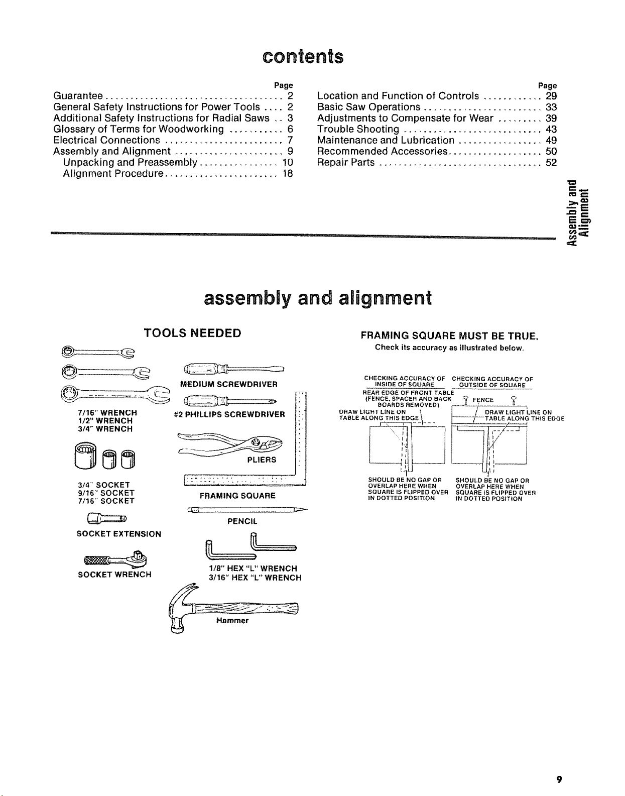
TOOLS NEEDED
MEDIUM SCREWDRIVER
7/16" WRENCH
1/2" WRENCH
3/4" WRENCH
#2 PHILLIPS SCREWDRIVER
Page
Location and Function of Controls ............ 29
Basic Saw Operations ........................... 33
Adjustments to Compensate for Wear ......... 39
Trouble Shooting .............................. 43
Maintenance and Lubrication .................. 49
Recommended Accessories ................... 50
Repair Parts ................................. 52
FRAMING SQUARE MUST BE TRUE,
Check its accuracy as illustrated below
CHECKING ACCURACY OF CHECKING ACCURACY OF
INSIDE OF SQUARE OUTSIDE OF SQUARE
REAR EDGE OF FRONT TABLE
(FENCE, SPACER AND BACK _ FENCE
DRAW LIGHT LiNE ON _ _ / DRAW LIGHT L|NE ON
TABLE ALONG THIS EDGE I j_'i--TABLE ALONG THtS EDGE
EIOARDS REMOVED) f- "--=_/ ....
o=1 (,rt
=
o,}-_
,=_
3/4" SOCKET
9/16" SOCKET
7/16" SOCKET
SOCKET EXTENSION
SOCKET WRENCH
PLIERS
FRAMING SQUARE
PENCIL
1/8" HEX "L" WRENCH
3/16" HEX "L" WRENCH
SHOULD 8E NO GAP OR SHOULD BE NO GAP OR
OVERLAP HERE WHEN OVERLAP HERE WHEN
SQUARE IS FLIPPED OVER SQUARE iS FLIPPED OVER
tN DOTTED POSITION IN DOTTED POSITION
t_lU LJIL J
9
unpacking and pteassembly
ITEM
NOo DESCRIPTION QTY,.
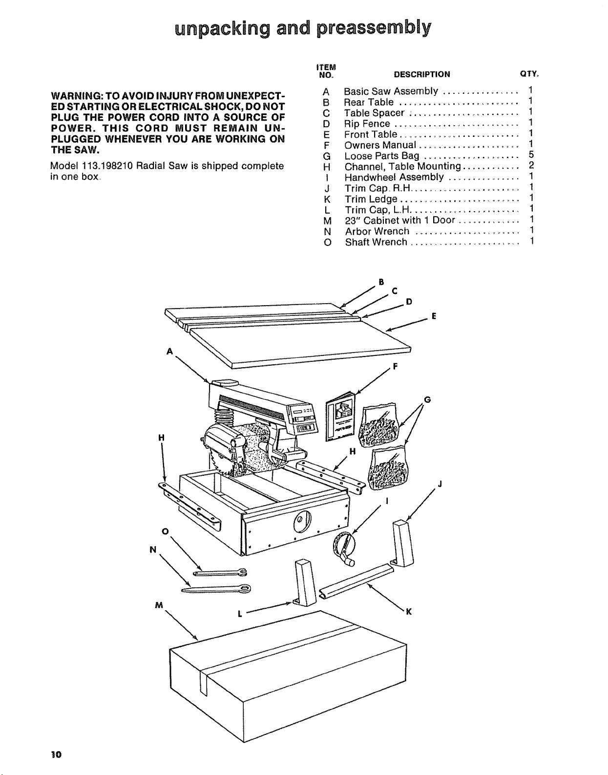
WARNING: TO AVOID INJURY FROM UNEXPECT-
ED STARTING OR ELECTRICAL SHOCK, DO NOT
PLUG THE POWER CORD INTO A SOURCE OF
POWER. THIS CORD MUST REMAIN UN-
PLUGGED WHENEVER YOU ARE WORKING ON
THE SAW.
Model 113.198210 Radial Saw is shipped complete
in one box
A
A Basic Saw Assembly ................ 1
B Rear Table ......................... 1
C Table Spacer : ...................... 1
D Rip Fence ........................... I
E Front Table ......................... 1
F Owners Manual ...................... 1
G Loose Parts Bag ..................... 5
H Channel, Table Mounting ............ 2
1 Handwheef Assembly ............... 1
J Trim Cap, R.H ......................... 1
K Trim Ledge ............................. 1
L Trim Cap, L.H....................... 1
M 23" Cabinet with 1 Door .............. 1
N Arbor Wrench ....................... 1
O Shaft Wrench ........................ 1
C
D
F
G
H
H
,/
M
\
I0
unpacking and checking contents
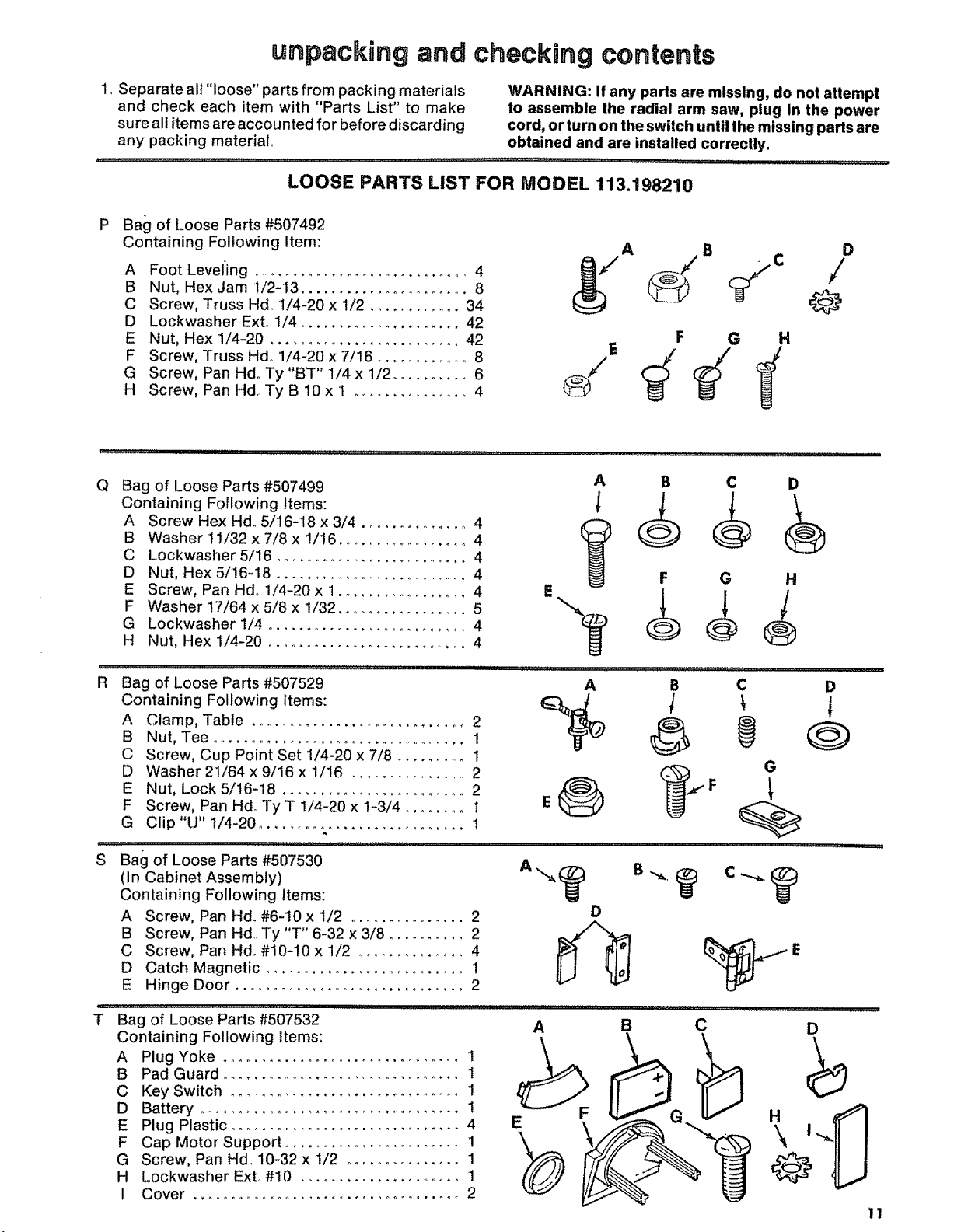
1, Separate all "loose" parts from packing materials WARNING: If any parts are missing, do not attempt
and check each item with "Parts List" to make to assemble the radial arm saw, plug in the power
sure all items are accounted for before discarding cord, or turn on the switch until the missing parts are
any packing material obtained and are installed correclly.
LOOSE PARTS LIST FOR MODEL 113.198210
P
Bag of Loose Parts #507492
Containing Following Item:
A Foot LevelLing ............................. 4
B Nut, Hex Jam 1/2-13 ...................... 8
C Screw, Truss Hd. 1/4-20 x 1/2 ............ 34
D Lockwasher Exto 1/4 ..................... 42
E Nut, Hex 1/4-20 .......................... 42
F Screw, Truss Hdo 1/4-20 x 7/16 ............ 8
G Screw, Pan Hdo Ty "BT" 1/4 x 1/2 .......... 6
H Screw, Pan Hd. Ty B 10 x 1 ............... 4
A B
F G H
D
/
@
Q
Bag of Loose Parts #507499
Containing Following Items:
A Screw Hex Hd, 5/16-18 x 3/4 .............. 4
B Washer!1i32x7/8x !/16 ................. 4
C Lockwasher 5/16 .......................... 4
D Nut, Hex 5/16-18 ........................... 4
E Screw, Pan Hd. 1/4-20 x 1.................. 4
F Washer 17/64 x 5/8 x 1/32 .................. 5
G Lockwasher 1/4 ........................... 4
H Nut, Hex 1/4-20 ............................ 4
R Bag of Loose Parts #507529 A B C
A Clamp, Table .............................. 2
Containing Following Items: _ _ _
B Nut, Tee .................................. 1
C Screw, Cup Point Set 1/4-20 x 7/8 .......... 1
D Washer 21/64 x 9/16 x 1/16 ................ 2
E Nut, Lock 5/16-I8 ........................ 2 ,/_,, _,,_. F
F Screw, Pan Hd_ Ty T 1/4-20 x 1-3/4 ........ 1 E
G Clip"U" 1/4-20 ........................... 1
S
Bali of Loose Parts #507530
(In Cabinet Assembly)
Containing Following Items:
A Screw, Pan Hd. #6-10 x 1/2 ............... 2
B Screw, Pan Hd. Ty "T" 6-32 x 3/8 .......... 2
C Screw, Pan Hd. #10-10 x 1/2 .............. 4
D Catch Magnetic .......................... 1
E Hinge Door ............................... 2
i,,i,,,i,,,i1,1111111,1,1 i,ii, ,
T Bag of Loose Parts #507532
Containing Following Items:
A
Plug Yoke ................................ 1
B
Pad Guard ................................ 1
C
Key Switch .............................. 1
D
Battery .................................... !
E
Plug Plastic .............................. 4
F
Cap Motor Support ....................... 1
G
Screw, Pan Hal. 10-32 x 1/2 ............... 1
H
Lockwasher Ext. #I0 ....................... 1
I
Cover ................................... 2
E
A B
E
A B C
F G
D
C
D
H
D
G
,,ll .........
i,i. i i
D
\l
@
11
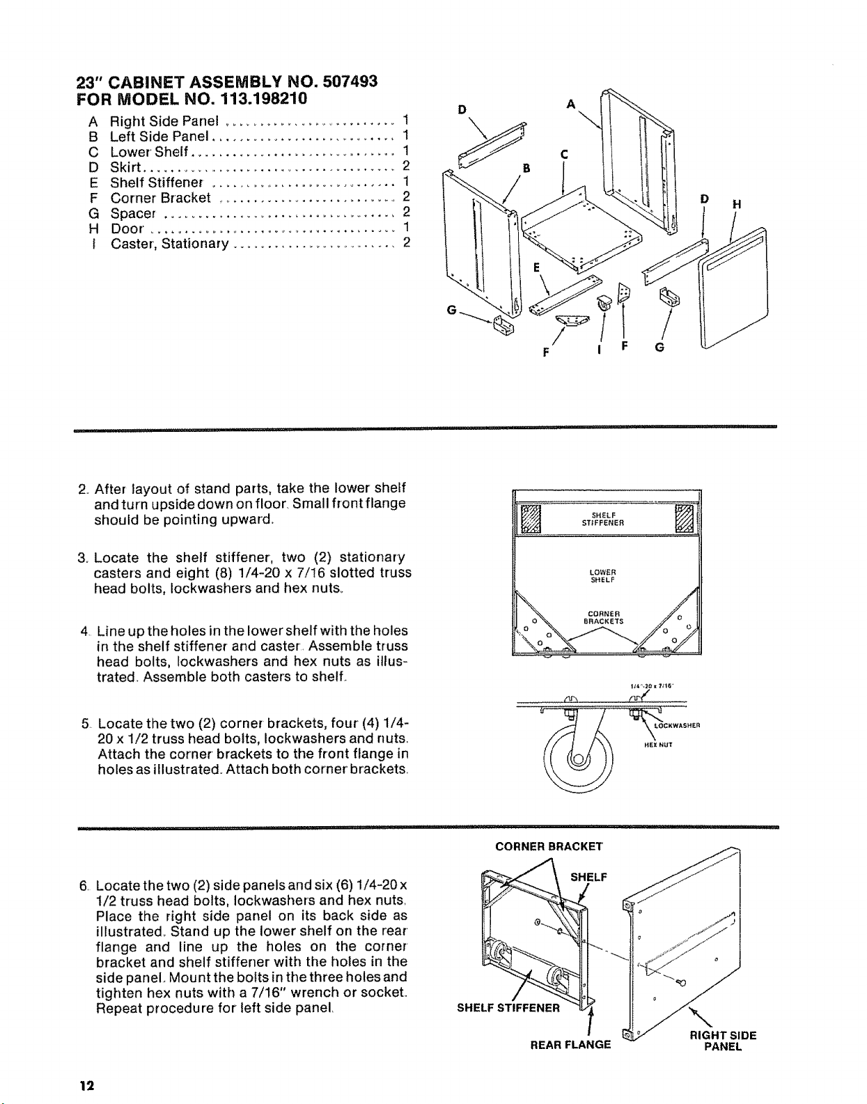
23" CABINET ASSEMBLY NO. 507493
FOR MODEL NO. 113.198210
A Right Side Panel ............................ 1
B Left Side Panel ........................... 1
C Lower' Shelf ............................... 1
D Skirt ....................................... 2
E Shelf Stiffener . ........................... 1
F Corner Bracket ............................ 2
G Spacer ................................... 2
H Door'......................................1
t Caster, Stationary ......................... 2
D
A
H
%
................ i i ii i:llllllllll i i lllllll i,iii, lUlHI
2. After layout of stand parts, take the lower shelf
and turn upside down on floor. Small front flange
should be pointing upward.
3o Locate the shelf stiffener, two (2) stationary
casters and eight (8) 1/4-20 x 7/!6 slotted truss
head bolts, Iockwashers and hex nuts.
4 Line up the holes in the lower shelf with the holes
in the shelf stiffener and caster Assemble truss
head bolts, Iockwashers and hex nuts as illus-
trated. Assemble both casters to shell
5 Locate the two (2) corner brackets, four (4) 1/4-
20 x 1/2 truss head bolts, Iockwashers and nuts
Attach the corner brackets to the front flange in
holes as illustrated. Attach both corner brackets
F i F
SHELF
STIFFENER
LOWER
SHELF
/lr'.i r,r_ /
G
I_e,".;10x ?;1_i'
6 Locatethe two (2) side panelsand six (6) 1/4-20 x
1/2 truss head bolts, Iockwashers and hex nuts
Place the right side panel on its back side as
illustrated_ Stand up the lower shelf on the rear
flange and line up the holes on the corner
bracket and shelf stiffener with the holes in the
side panel. Mount the bolts inthe three holes and
tighten hex nuts with a 7/16" wrench or socket
Repeat procedure for left side panel
12
CORNER BRACKET
SHELF STIFFENER
REAR FLANGE
SHELF
RIGHT SIDE
PANEL
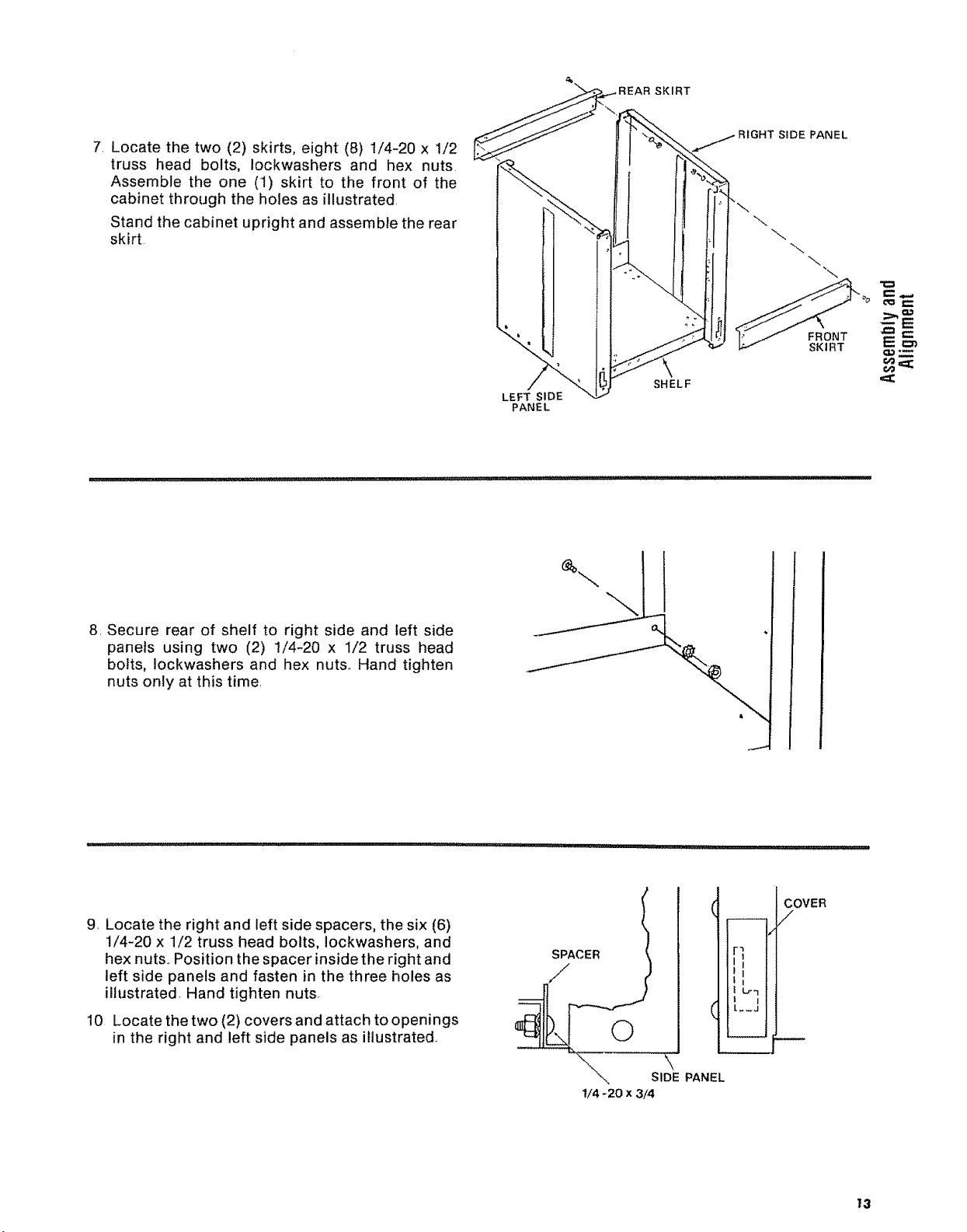
7. Locate the two (2) skirts, eight (8) 1/4-20 x 1/2
truss head bolts, Iockwashers and hex nuts.
Assemble the one (1) skirt to the front of the
cabinet through the holes as illustrated.
Stand the cabinet upright and assemble the rear
skirt
SKIRT
SIDE PANEL
\
"\
FRONT
SKIRT
8. Secure rear of shelf to right side and left side
panels using two (2) 1/4-20 x 1/2 truss head
bolts, Iockwashers and hex nuts.. Hand tighten
nuts only at this time.
LEFT SIDE
PANEL
SHELF
9. Locate the right and left side spacers, the six (6)
1/4-20 x 1/2 truss head bolts, Iockwashers, and
hex nuts.. Position the spacer inside the right and
left side panels and fasten in the three holes as
illustrated. Hand tighten nuts.
I0 Locate the two (2) covers and attach to openings
in the right and left side panels as illustrated..
i_ll ,,i,1,1,1,11, _111 i ,i ...... illl
SPACER
//
©
SIDE PANEL
t/4- 20 x 3/4
FI
L
!l I
i L._J
COVER
/
13
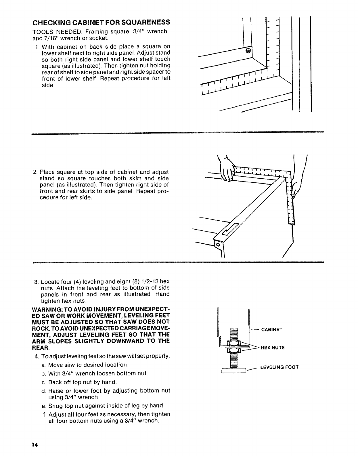
CHECKING CABINET FOR SQUARENESS
TOOLS NEEDED: Framing square, 3/4" wrench
and 7/16" wrench or socket.
1 With cabinet on back side place a square on
lower shelf next to right side panel, Adjust stand
so both right side panel and lower shelf touch
square (as illustrated) Then tighten nut holding
rear of shelf to side panel and right side spacer to
front of lower shelf Repeat procedure for left
side,
i , , i,ii,,, rlH"' ,ill i,ilrl :
2 PIace square at top side of cabinet and adjust
stand so square touches both skirt and side
panel (as illustrated) Then tighten right side of
front and rear skirts to side panel, Repeat pro-
cedure for left side°
3, Locate four (4) leveling and eight (8) !/2-13 hex
nuts Attach the leveling feet to bottom of side
panels in front and rear as illustrated, Hand
tighten hex nuts.
WARNING: TO AVOID INJURY FROM UNEXPECT-
ED SAW OR WORK MOVEMENT, LEVELING FEET
MUST BE ADJUSTED SO THAT SAW DOES NOT
ROCK. TO AVOID UNEXPECTED CARRIAGE MOVE-
MENT, ADJUST LEVELING FEET SO THAT THE
ARM SLOPES SLIGHTLY DOWNWARD TO THE
REAR.
4. To adjust leveling feet so the saw will set properly:
a Move saw to desired location
b, With 3/4" wrench loosen bottom nut,
c. Back off top nut by hand
d Raise or lower foot by adjusting bottom nut
using 3/4" wrench,
e, Snug top nut against inside of leg by hand,
f, Adjust all four feet as necessary, then tighten
all four bottom nuts using a 3/4" wrench
t4
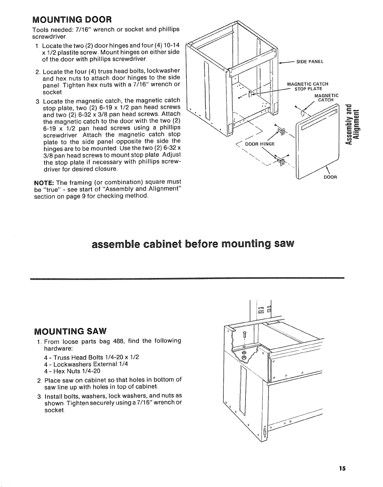
iVIOUNTBNG DOOR
Tools needed: 7/16" wrench or socket and phillips
screwd river,
1, Locate the two (2) door hinges and four (4) 10-14
x 1/2 plastite screw, Mount hinges on either side
of the door with phillips screwdriver,
2, Locate the four (4) truss head bolts, lockwasher
and hex nuts to attach door hinges to the side
panel, Tighten hex nuts with a 7/16" wrench or
socket
3 Locate the magnetic catch, the magnetic catch
stop plate, two (2) 6-19 x 1/2 pan head screws
and two (2) 6-32 x 3/8 pan head screws, Attach
the magnetic catch to the door with the two (2)
6-19 x 1/2 pan head screws using a phillips
screwdriver, Attach the magnetic catch stop
plate to the side panel opposite the side the
hinges are to be mounted. Use the two (2) 6-32 x
3/8 pan head screws to mount stop plate Adjust
the stop plate if necessary with phillips screw-
driver for desired closure,
NOTE: The framing (or combination) square must
be "true" - see start of "Assembly and Alignment"
section on page 9 for checking method.,
MAGNETIC CATCH
STOP PLATE
MAGNETIC
CATCH
\
assembae cabinet before mounting saw
NIOUNTING SAW
1., From loose parts bag 488, find the following
hardware:
4 - Truss Head Bolts 1/4-20 x 1/2
4- Lockwashers External 1/4
4- Hex Nuts 1/4-20
2. Place saw on cabinet so that holes in bottom of
saw line up with holes in top of cabinet,,
3 Install bolts, washers, lock washers, and nuts as
shown. Tighten securety using a 7/! 6" wrench or
socket,
15
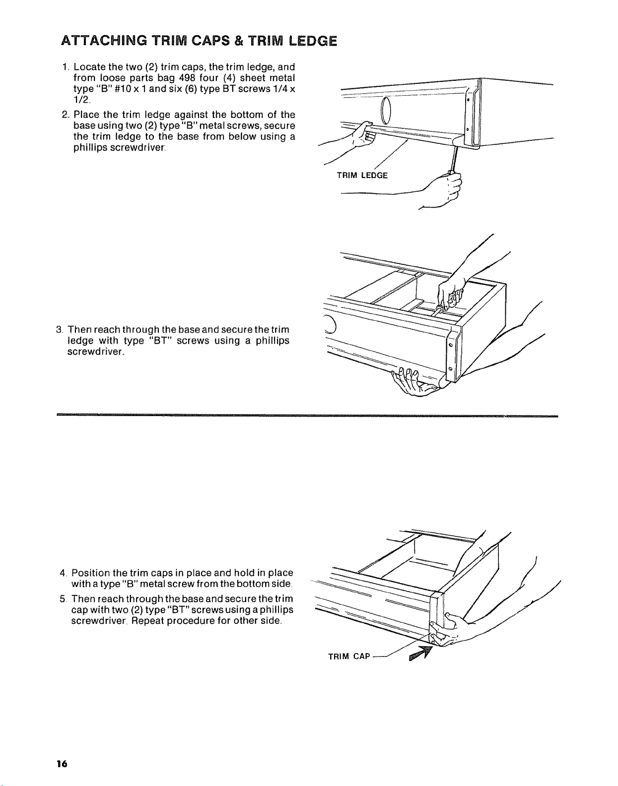
ATTACHING TRiM CAPS & TRiM LEDGE
1. Locate the two (2) trim caps, the trim ledge, and
from loose parts bag 498 four (4) sheet metal
type "B" #10 x i and six (6) type BT screws 1/4 x
1/2o
2_ Place the trim ledge against the bottom of the
base using two (2) type"B" metal screws, secure
the trim ledge to the base from below using a
phillips screwdriver.
TRIM LEDGE
3, Then reach through the base and secure the trim
ledge with type "BT" screws using a phillips
screwdriver_
4, Position the trim caps in place and hold in place
with a type "B" metal screw from the bottom side.
5. Then reach through the base and secure the trim
cap with two (2) type "BT" screws using a phillips
screwdriver. Repeat procedure for other side,
16
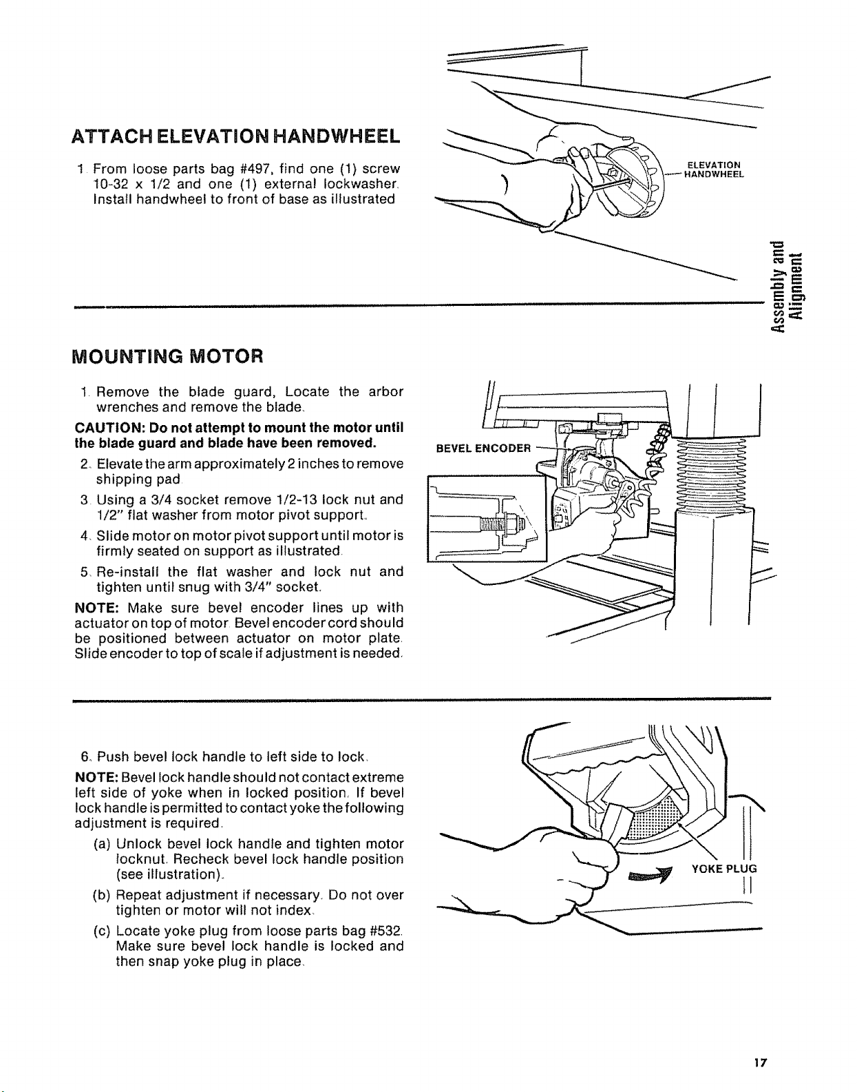
ATTACH ELEVATION HANDWHEEL
1 From loose parts bag #497, find one (1) screw
10-32 x 1/2 and one (I) external Iockwasher
Install handwheel to front of base as illustrated
MOUNTING MOTOR
1, Remove the blade guard, Locate the arbor
wrenches and remove the blade_
CAUTION: Do not attempt to mount the motor until
the blade guard and blade have been removed.
2 Elevate the arm approximately 2inches to remove
shipping pad
3. Using a 3/4 socket remove 1/2-13 lock nut and
1/2" flat washer from motor pivot support.,
4, Slide motor on motor pivot support until motor is
firmly seated on support as illustrated,
5, Re-install the flat washer and lock nut and
tighten until snug with 3/4" sockeL
NOTE: Make sure bevel encoder lines up with
actuator on top of motor Bevel encoder cord should
be positioned between actuator on motor plate,
Slide encoder to top of scale if adjustment is needed,
_,,,,
BEVEL ENCODER
ELEVATION
,IANDWHEEL
--E
6, Push bevel lock handle to left side to lock,
NOTE: Bevel lock handle shou Id not contact extreme
left side of yoke when in locked position, If bevel
lock handle is permitted to contact yoke the following
adjustment is required,
(a) Unlock bevel lock handle and tighten motor
locknut, Recheck bevel lock handle position
(see illustration).,
(b) Repeat adjustment if necessary. Do not over
tighten or motor will not index,
(c) Locate yoke plug from loose parts bag #532,
Make sure bevel lock handle is locked and
then snap yoke plug in place
YOKE PLUG
II
17
ALIIGNMENT PROCEDURE
IMPORTANT: In order to obtain maximum cutting
accuracy and safety, the following six steps must be
carefully followed° Become thoroughly familiar with
these steps so that you can always maintain your
saw in proper alignment° The accuracy of each
adjustment is always dependent upon the accuracy
of the preceeding adjustment.
Be sure to align the saw in the exact sequence
described to insure proper alignment and cutting
accuracy.
After following the 6 step assembly and alignment
procedure and the Basic Saw operation section refer
to Trouble Shooting section if any difficulty is
experienced when performing any sawing operation.
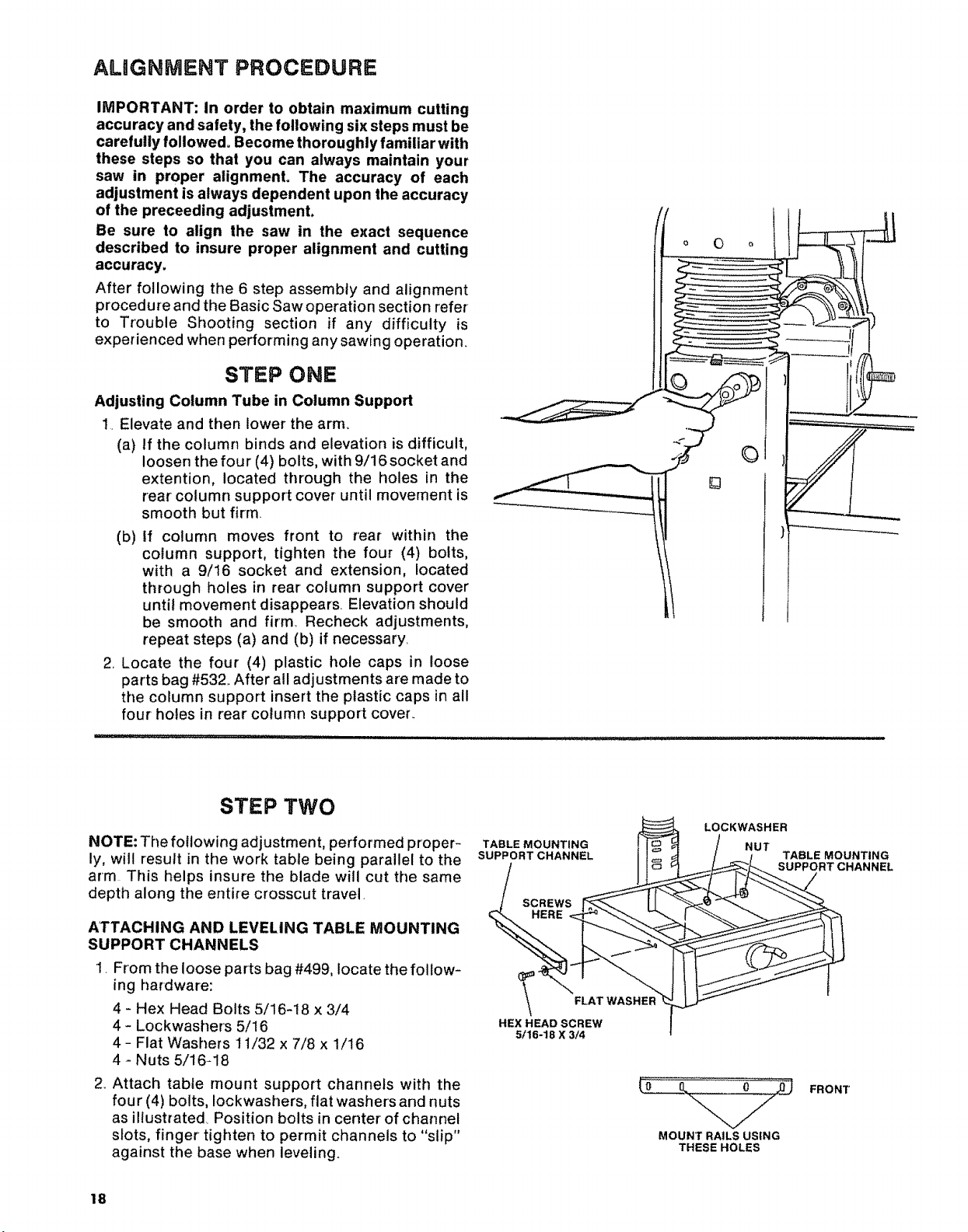
STEP ONE
Adjusting Column Tube in Column Support
1• Elevate and then lower the arm.
(a) If the column binds and elevation is difficult,
loosen the four (4) bolts, with 9/16 socket and
extention, located through the holes in the
rear column support cover until movement is
smooth but firm.
(b) If column moves front to rear within the
column support, tighten the four (4) bolts,
with a 9/16 socket and extension, located
through holes in rear column support cover
until movement disappears. Elevation should
be smooth and firm, Recheck adjustments,
repeat steps (a) and (b) if necessary.
2.. Locate the four (4) plastic hole caps in loose
parts bag #532_ After all adjustments are made to
the column support insert the plastic caps in all
four holes in rear column support cover.
STEP TWO
NOTE: The following adjustment, performed proper-
ly, will result in the work table being parallel to the
arm This helps insure the blade will cut the same
depth along the entire crosscut travel.
ATTACHING AND LEVELING TABLE MOUNTING
SUPPORT CHANNELS
i. From the loose parts bag #499, locate the follow-
ing hardware:
4 - Hex Head Bolts 5/16-18 x 3/4
4 - Lockwashers 5/16
4- Flat Washers 11/32 x 7/8 x 1/16
4 - Nuts 5/16-18
2. Attach table mount support channels with the
four (4) bolts, Iockwashers, flat washers and nuts
as illustrated Position bolts in center of channel
s_ots, finger tighten to permit channels to "slip"
against the base when leveling.
18
TABLE MOUNTING
SUPPORT CHANNEL
SCREWS
HERE
HEX HEAD SCREW
5/16-18 X 3/4
FLAT
LOCKWASHER
NUT
MOUNT RAILS USING
THESE HOLES
TABLE MOUNTING
SUPPORT CHANNEL
FRONT
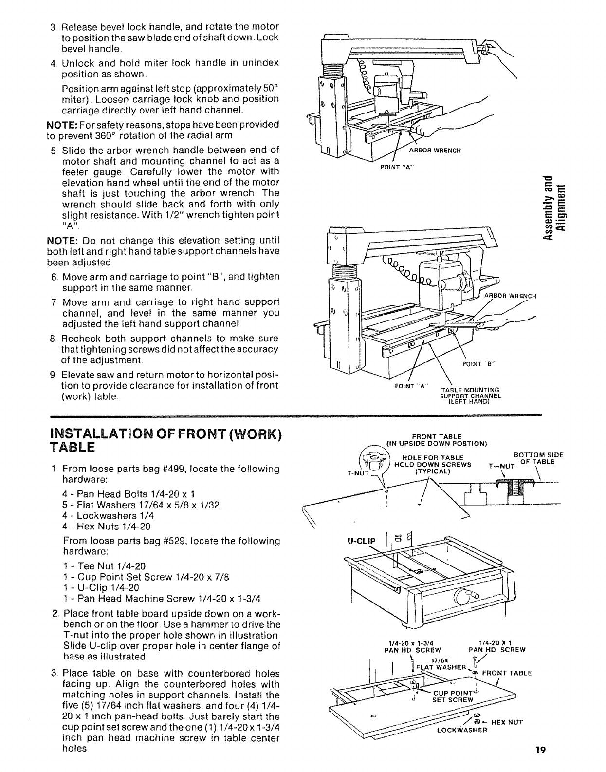
3 Releasebevellockhandle,androtatethemotor
topositionthesawbladeendofshaftdown.Lock
bevelhandle,
4 Unlockandholdmiterlockhandlein unindex
positionasshown,
Positionarmagainstleftstop(approximately50°
miter),Loosencarriagelockknobandposition
carriagedirectlyoverlefthandchannel
NOTE:Forsafetyreasons,stopshavebeenprovided
toprevent360° rotationoftheradialarm
5.Slidethearborwrenchhandlebetweenendof
motor shaft and mounting channel to act as a
feeler gauge, Carefully lower the motor with
elevation hand wheel until the end of the motor
shaft is just touching the arbor wrench The
wrench should slide back and forth with only
slight resistance,, With 1/2" wrench tighten point
I_A _
NOTE: Do not change this elevation setting until
both teft and right hand table support channels have
been adjusted
6 Move arm and carriage to point "B", and tighten
support in the same manner,
7 Move arm and carriage to right hand support
channel, and level in the same manner you
adjusted the teft hand support channel
8 Recheck both support channels to make sure
that tightening screws did not affect the accuracy
of the adjustment,
9, Elevate saw and return motor to horizontal posi-
tion to provide clearance for installation of front
(work) table.
F
ARBOR WRENCH
POINT "*A"
Em'_
€,o,==;
ARBOR WRENCH
POINT -A"
TABLE MOUNTING
SUPPORT CHANNEL
(LEFT HAND)
INSTALLATION OF FRONT (WORK)
TABLE
1 From loose parts bag #499, locate the following
hardware:
4 - Pan Head Bolts 1/4-20 x 1
5 - Flat Washers 17/64 x 5/8 x !/32
4 - Lockwashers 1/4
4 - Hex Nuts If4-20
From loose parts bag #529, locate the following
hardware:
t - Tee Nut 1/4-20
1 - Cup Point Set Screw 1/4-20 x 7/8
1 - U-Clip 1/4-20
1 - Pan Head Machine Screw 1/4-20 x I-3/4
2 Place front table board upside down on a work-
bench or on the floor. Use a hammer to drive the
T-nut into the proper hole shown in illustration
Slide U-clip over proper hole in center flange of
base as illustrated,
3. Place table on base with counterbored holes
facing up, Align the counterbored holes with
matching holes in support channels, lnstall the
five (5) 17/64 inch flat washers, and four (4) 1/4-
20 x 1 inch pan-head bolts, Just barely start the
cup point set screw and the one (1) 1/4-20 x !-3/4
inch pan head machine screw in table center
holes,
IJ-CLIP
FRONT TABLE
1/4-20 x %3/4
PAN HD SCREW
1/4-20 X 1
PAN HD SCREW
19
4.Installone(1)1/4Iockwasherandhexnut on
each of the four' (4) screwsin the support
channels,andtightenusingphillipsscrewdriver
and7/16wrenchor'socket.
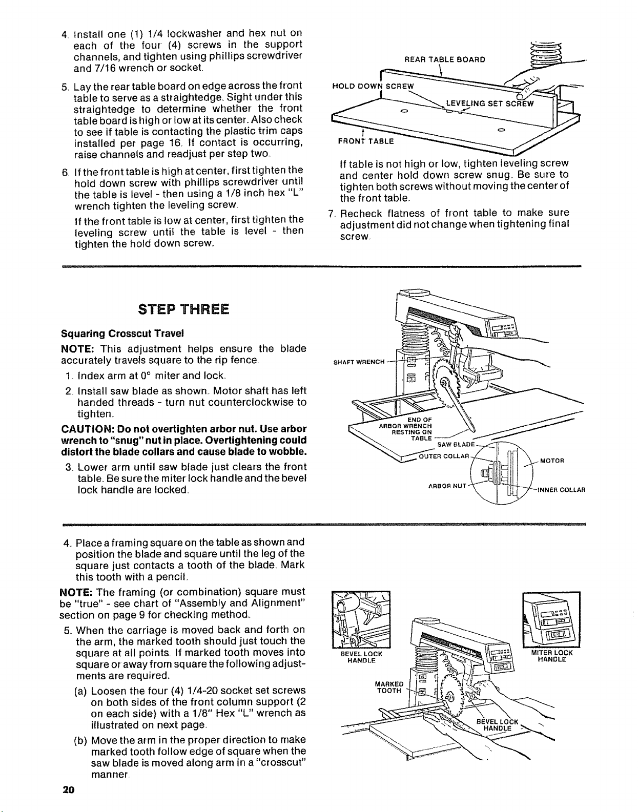
5.Laythereartableboardonedgeacrossthefront
tabletoserveasastraightedge_Sightunderthis
straightedgeto determinewhetherthe front
tableboardishighorlowatitscenter.Alsocheck
toseeiftableiscontactingtheplastictrimcaps
installedperpage16.If contactis occurring,
raisechannelsandreadjustpersteptwo.,
6.Ifthefronttableishighatcenter,firsttightenthe
holddownscrewwith phillipsscrewdriveruntil
thetableislevel-thenusinga1/8inchhex"L"
wrenchtightenthelevelingscrew.
Ifthefronttableislowatcenter,firsttightenthe
levelingscrew unti! the table is level- then
tightentheholddownscrew°
STEP THREE
tftableisnothighor low,tightenlevelingscrew
andcenterholddownscrewsnug.Be sureto
tightenbothscrewswithoutmovingthecenter'of
thefronttable..
7..Recheckflatnessof front tableto makesure
adjustmentdidnotchangewhentighteningfinal
screw..
Squaring Crosscut Travel
NOTE: This adjustment helps ensure the blade
accurately travels square to the rip fence,
1, Index arm at 0° miter and lock,,
2 Install saw blade as shown.. Motor shaft has left
handed threads - turn nut counterclockwise to
tighten_
CAUTION: Do not overtighten arbor nut. Use arbor
wrench to "snug" nut in place. Overtightening could
distort the blade collars and cause blade to wobble.
3. Lower arm until saw blade just clears the front
table. Be sure the miter lock handle and the bevel
lock handle are locked.
4.. Place a framing square on the table as shown and
position the blade and square until the leg of the
square just contacts a tooth of the blade. Mark
this tooth with a pencil,
NOTE: The framing (or combination) square must
be "true" - see chart of "Assembly and Alignment"
section on page 9 for checking method.
5, When the carriage is moved back and forth on
the arm, the marked tooth should just touch the
square at all points.. If marked tooth moves into
square or away from square the following adjust-
ments are required,
(a) Loosen the four (4) 1/4-20 socket set screws
on both sides of the front column support (2
on each side) with a 1/8" Hex "L" wrench as
illustrated on next page
(b) Move the arm in the proper direction to make
marked tooth follow edge of square when the
saw blade is moved along arm in a "crosscut"
manner'.
2O
SH
BEVEL LOCK
HANDLE
MARKED
TOOTH
MITER LOCK
HANDLE
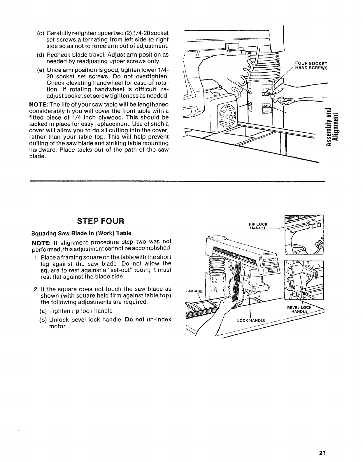
(c) Carefully retighten tJpper two (2) 1/4_20 socket
set screws alternating from left side to right
side so as not to force arm out of adjustment°
(d) Recheck blade travel° Adjust arm position as
needed by readjusting upper screws only,
(e) Once arm position is good, tighten lower 1/4-
20 socket set screws. Do not overtighten.
Check elevating handwheel for ease of rota-
tion., If rotating handwhee! is difficult, re-
adjust socket set screw tighteness as needed.
NOTE: The life of your saw table will be lengthened
considerably if you will cover the front table with a
fitted piece of 1/4 inch plywood° This should be
tacked in place for easy replacemenL Use of such a
cover will allow you to do all cutting into the cover,
rather than your table top,. This will help prevent
dulling of the saw blade and striking table mounting
hardware., Place tacks out of the path of the saw
blade°
FOUR SOCKET
HEAD SCREWS
STEP FOUR
Squaring Saw Blade to (Work) Table
NOTE: if alignment procedure step two was not
performed, this adjustment cannot be accomplished,
1, Place a framing square on the table with the short
leg against the saw blade Do not allow the
square to rest against a "set-out" tooth; it must
rest flat against the blade side,,
2. If the square does not touch the saw blade as
shown (with square held firm against table top)
the following adjustments are required.
(a) Tighten rip lock handle.
(b) Unlock bevel lock handle Do not un-index
motor
SQUARE
\
2!
 Loading...