

Craftsman 11319761, 113197601 Owner’s Manual
Sears
owners
manual
MODEL NO.
113.19761
Serial
Number
Model and serial
number may be found
at the front of the base.
You should record both
model and serial number
in a safe place for
future use.
CAUTION:
Read GENERAL
and ADDITIONAL
SAFETY
INSTRUCTIONS
carefully
CRRFTSMRNo
IO-INCH
RADIAL SAW
• assembly
• operating
• repair parts
Sold by SEARS, ROEBUCK AND CO., Chicago, IL. 60684 U.S.A.
Part No. 63783 Plinted in U.S.A.
FULL ONE YEAR WARRANTY ON CRAFTSMAN RADIAL SAW
If within one year from the date of purchase, this Craftsman Radial Saw fails due to a defect in material or
workmanship, Sears will repair it, free of charge.
WARRANTY SERVICE IS AVAILABLE BY SIMPLY CONTACTING THE NEAREST SEARS STORE
OR SERVICE CENTER THROUGHOUT THE UNITED STATES.
This warranty gives you specific legal rights, and you may have other rights which vary from state to state.
SEARS, ROEBUCK AND CO., Sears Tower, BSC 41-3, Chicago, IL 60684
general safety instructions for power tools
1. KNOW YOUR POWER TOOL
Read the owner's manual carefully. Learn its
application and limitations as well as the specific
potential ha.,ards peculiar to this tool. 13.
2. GROUND ALL TOOLS
This tool is equipped with an approved 3-conductor
cord and a 3-prong grounding type plug to fit the
proper grounding type receptacle. The green conductor 14.
in the cord _s the grounding wire. Never connect the
green wire t() a live terminal. 15.
3. KEEP GUARDS IN PLACE
in working order, and in proper adjustment and
alignment.
4. REMOVE ADJUSTING KEYS 16.
AND WRENCHES
Form habit of checking to see that keys and adjusting
wrenches are removed from tool before turning it on.
5. KEEP WORK AREA CLEAN
Cluttered aweas and benches invite accidents. Floor
must not be slippery due to wax or sawdust.
6. AVOID DANGEROUS ENVIRONMENT
Don't use power tools in damp or wet locations or
expose them to rain. Keep work area well lighted.
Provide adequate surrounding work space.
7. KEEP CHILDREN AWAY 19.
All visitors should be kept a safe distance from work
area.
8. MAKE WORKSHOP KID-PROOF
with padlocks, master switches, or by removing
starter keys.
9. DON'T FORCE TOOL
It will do the job better and safer at the rate for which
it was designed.
10. USE RIGHT TOOL
Don't force tool or attachment to do a job it was not
designed for
11. WEAR PROPER APPAREL
Do not wear loose clothing, gloves, neckties or jewelry
(rings, wrist watches) to get caught in moving parts.
Nonslip footwear is recommended. Wear protective
hair covering to contain long hair. Roll long sleeves
above the elbow.
12. USE SAFETY GOGGLES (Head Protection)
Wear Safety goggles (must comply with ANSI Z87.1)
at all times. Everyday eyeglasses only have impact
resistant lenses, they are NOT safety glasses. Also, use
face or dust mask if cutting operation is dusty, and ear
protectors (plugs or muffs) during extended periods of
operation.
SECURE WORK
Use clamps or a vise to hold work when practical. It's
safer than using your hand, frees both hands to operate
tool.
DON'T OVERREACH
Keep proper footing and balance at all times.
MAINTAIN TOOLS WITH CARE
Keep tools sharp and clean for best and safest
performance. Follow instructions for lubricating and
changing accessories.
DISCONNECT TOOLS
before servicing; when changing accessories such as
blades, bits, cutters, etc.
17.
AVOID ACCIDENTAL STARTING
Make sure switch is in "OFF" position before plugging
I n.
18.
USE RECOMMENDED ACCESSORIES
Consult the owner's manual for recommended
accessories. Follow the instructions that accompany
the accessories. The use of improper accessories may
cause hazards.
NEVER STAND ON TOOL
Serious injury could occur if the tool is tipped or if the
cutting too! is accidentally contacted.
Do not store materials above or near the tool such that
it is necessary to stand on the tool to reach them.
20. CHECK DAMAGED PARTS
Before further use of the tool, a guard or other part that
is damaged should be carefully checked to ensure that it
will operate propedy and perform its intended function.
Check for alignment of moving parts, binding of moving
parts, breakage of parts, mounting, and any other
conditions that may .affect its operation. A guard or
other part that is damaged should be properly repaired
or replaced.
21. DIRECTION OF FEED
Feed work into a blade or cutter against the direction
of rotation of the blade or cutter only.
22.
NEVER LEAVE TOOL RUNNING
UNATTENDED
Turn power off. Don't leave tool until it comes to a
complete stop.
additional safety instructions for radial saws
CAUTION: Always disconnect the power cord before
removing the guard, changing the cutting tool, changing the
set-up or making adjustments. Shut off motor before
performing layout work on the saw table.
WARNING: DO NOT CONNECT POWER CORD UNTIL
THE FOLLOWING STEPS HAVE BEEN
SATISFACTORI LY COMPLETED:
I. Assembly and alignment.
II. Examination and operating familiarity with ON-OFF
switch, elevation control, yoke index and lock bevel
index and lock, carriage lock, guard clamp screw,
spreader and antikickback device, and miter index and
lock.
III. Review and understanding of all Safety Instructions and
Operating Procedures thru-out manual,
INSTALLATION
I. Set carriage lock before moving the saw.
2. Bolt the saw to the floor if it tends to slip, walk, or
slide during normal operation.
3. Mount the saw so the table is approximately 39" above
the floor.
4. Mount the saw so the arm slopes slightly downward to
the rear so the carriage will not roll forward due to
gravity.
MINIMIZE ACCIDENT POTENTIAL
Most accidents are caused by FAILURE TO FOLLOW
setup and operating instructions:
(A) GENERAL
-Avoid awkward hand positions, where a sudden slip
could cause a hand to move into a sawblade or other
cutting tool. Never reach in back of or around the
cutting tool with either hand to hold down the
workpiece, or for any other reason; DO NOT place
fingers or hands in the path of the sawblade.
Never saw, dado, mold, or rabbet unless the proper
guard is installed and set up as instructed.
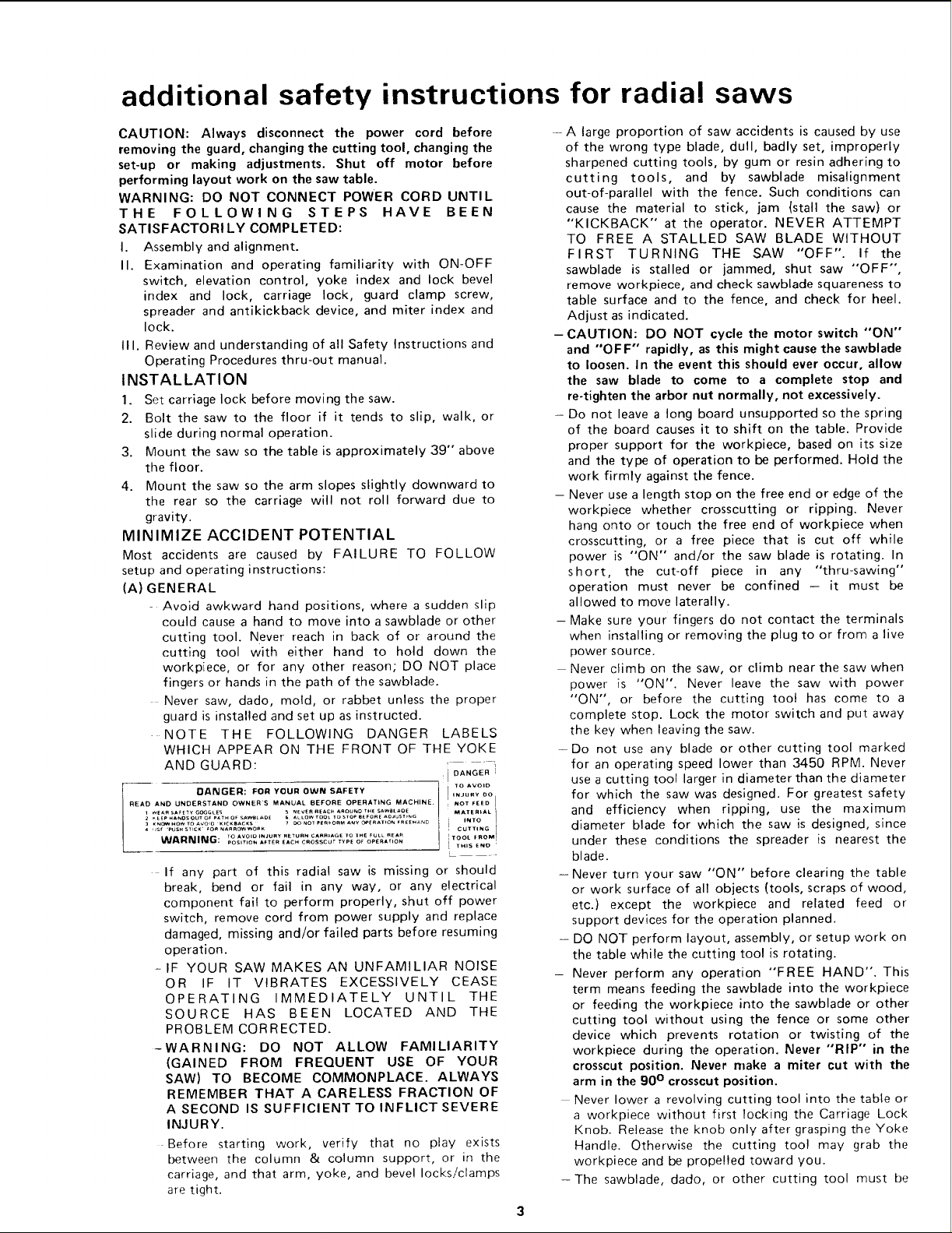
NOTE THE FOLLOWING DANGER LABELS
WHICH APPEAR ON THE FRONT OF THE YOKE
AND GUARD: i DANGERI
READ AND UNDERSTAND OWNERS MANUAL BEFORE OPERATING MACHINE. i NOT FEED I
3 KNOV,HOWTOAvo,o K,CK=ACKS _ NOT PE_OAU A_Y O_ERAT'ON _REEHAND INTO
= ,Jsr 'PUSHS,,CK _OaNA.ROWWO_K ! CUTTING i
DANGER: FOR YOUR OWN SAFETY ] TO AVOID
WeA_ SA_TY GOGG,ES s NEVER REACH AAOUNO THE SAwetAOE MATERIAL 1. EePHANDSOUT OFPAtH OF SAWSLAO[ ALLOWrOOt TO STOPeEFORZAOJUSTPNG
WARNING: TO AVOID INJURY RETURN CARRIAGE IO IHE FULL REAR _TOOL FROM,
POSITION AFTER EACH CROSSCUT TYPE OF OperATION I ,
If any part of this radial saw is missing or should
break, bend or fail in any way, or any electrical
component fail to perform properly, shut off power
switch, remove cord from power supply and replace
damaged, missing and/or failed parts before resuming
operation.
- IF YOUR SAW MAKES AN UNFAMILIAR NOISE
OR IF IT VIBRATES EXCESSIVELY CEASE
OPERATING IMMEDIATELY UNTIL THE
SOURCE HAS BEEN LOCATED AND THE
PROBLEM CORRECTED.
-WARNING: DO NOT ALLOW FAMILIARITY
(GAINED FROM FREQUENT USE OF YOUR
SAW) TO BECOME COMMONPLACE. ALWAYS
REMEMBER THAT A CARELESS FRACTION OF
A SECOND IS SUFFICIENT TO INFLICT SEVERE
INJURY.
Before starting work, verify that no play exists
between the column & column support, or in the
carriage, and that arm, yoke, and bevel locks!clamps
are tight.
' " 3
INJURY DO
[ THIS END
--A large proportion of saw accidents is caused by use
of the wrong type blade, dull, badly set, improperly
sharpened cutting tools, by gum or resin adhering to
cutting tools, and by sawblade misalignment
out-of-parallel with the fence. Such conditions can
cause the material to stick, jam {stall the saw) or
"KICKBACK" at the operator. NEVER ATTEMPT
TO FREE A STALLED SAW BLADE WITHOUT
FIRST TURNING THE SAW "OFF". If the
sawblade is stalled or jammed, shut saw "OFF",
remove workpiece, and check sawblade squareness to
table surface and to the fence, and check for heel.
Adjust as indicated.
-CAUTION: DO NOT cycle the motor switch "'ON'"
and "OFF" rapidly, as this might cause the sawblade
to loosen. In the event this should ever occur, allow
the saw blade to come to a complete stop and
re-tighten the arbor nut normally, not excessively.
- Do not leave a long board unsupported so the spring
of the board causes it to shift on the table. Provide
proper support for the workpiece, based on its size
and the type of operation to be performed. Hold the
work firmly against the fence.
- Never use a length stop on the free end or edge of the
workpiece whether crosscutting or ripping. Never
hang onto or touch the free end of workpiece when
crosscutting, or a free piece that is cut off while
power is "ON" and/or the saw blade is rotating. In
short, the cut-off piece in any "thru-sawing"
operation must never be confined - it must be
allowed to move laterally.
- Make sure your fingers do not contact the terminals
when installing or removing the plug to or from a live
power source.
Never climb on the saw, or climb near the saw when
power is "'ON". Never leave the saw with power
"ON", or before the cutting toot has come to a
complete stop. Lock the motor switch and put away
the key when leaving the saw.
-Do not use any blade or other cutting tool marked
for an operating speed lower than 3450 RPM. Never
use a cutting tool larger in diameter than the diameter
for which the saw was designed. For greatest safety
and efficiency when ripping, use the maximum
diameter blade for which the saw is designed, since
under these conditions the spreader is nearest the
blade.
- Never turn your saw "ON" before clearing the table
or work surface of all objects (tools, scraps of wood,
etc.) except the workpiece and related feed or
support devices for the operation planned.
- DO NOT perform layout, assembly, or setup work on
the table while the cutting tool is rotating.
- Never perform any operation "FREE HAND". This
term means feeding the sawblade into the workpiece
or feeding the workpiece into the sawblade or other
cutting tool without using the fence or some other
device which prevents rotation or twisting of the
workpiece during the operation. Never "'RIP" in the
crosscut position. Never make a miter cut with the
arm in the 90 ° crosscut position.
Never lower a revolving cutting tool into the table or
a workpiece without first locking the Carriage Lock
Knob. Release the knob only after grasping the Yoke
Handle. Otherwise the cutting tool may grab the
workpiece and be propelled toward you.
-The sawblade, dado, or other cutting tool must be
additional safety
removed from the saw arbor before using the
accessory shaft (rear end of the saw motor). NEVER
operate the saw with cutting tools (including sanding
accessories) installed on both ends of the saw arbor.
(B) RIPPING
Ripping is cutting with the grain or the long way of the
board - it is performed by pushing the workpiece
along the fence and thru the sawblade (sawblade
parallel to the fence).
1. Never apply the feed force to the section of the
workpiece that will become the cut-off (free) piece.
Feed force when ripping must always be applied
between the saw blade and the fence . . . use a
"PUSH STICK" (see pg. 26) for narrow or short
work.
2. Whenever possible, use the in-rip position - this
provides minimum obstruction f_r feeding by hand
or push stick as appropriate.
3. Do not release the workpiece before operation is
complete - push the workpiece all the way past the
rear (outfeed or exit) of the sawblade.
4. Make sure by trial before starting the cut that the
antikickback pawls will stop a kickback once it has
started. Keep points of pawls SHARP!
5. Use a push stick when ripping short (under 12
inches) or narrow (under 6 inches wide) workpieces.
6. CAUTION: Never reposition the Guard or
antikickback with power "ON".
7. A "KICKBACK" occurs during a rip-type operation
when a part or all of the workpiece is thrown back
violently toward the operator. It can occur when
the workpiece closes in on the rear (outfeed side) of
the sawblade (pinching), binds between the fence
and the sawblade (heel), or is grabbed by the
sawblade teeth (wrong-way feed) at the outfeed
side. "PINCHING" is generally avoided by
utilization of the spreader, and a sharp sawblade of
the correct type for the workpiece being cut.
"HEEL" can be avoided by maintaining the
sawblade exactly parallel to the fence. Grabbing by
the sawblade teeth can be caused by heel or by
feeding from the wrong direction (see "DANGER"
warning on guard) - it can be avoided by
maintaining parallelism of sawblade to fence,
feeding into the sawblade from the nose of the
guard only, by positioning the spreader and
antikickback properly, and keeping the workpiece
down on the table and against the fence.
8. Position the nose of the guard to just clear the
workpiece, and position/adjust the antikickback
and spreader devices as instructed.
9. NEVER cut more than one piece at a time by
stacking workpieces vertically.
10. NEVER feed a workpiece thru the saw with another
p}ece {butt{rig second piece against trailing edge of
piece being cut), even if of the same thickness. Feed
each workpiece individually thru the sawblade, and
completely beyond the sawblade, before ripping the
next workpiece. Use push stick if the rip cut is less
than 6" wide.
1 1. DO NO _- pull the workpiece thru the sawblade
- position your body at the nose (in-feed) side of the
guard: start and complete the cut from that same
side. This will require added table support for long
pieces.
12. Plastic and composition (like hardboard)materials
may be cut on your saw. However, since these are
usually quite hard and slippery, the antikickback
pawls may not stop a kickback.
instructions for radial saws
Therefore, rip with the finished side down (next to
the table) and be especially attentive to following
proper set-up and cutting procedures. Do not stand,
or permit anyone else to stand, in line with a
potential kickback.
13. When sawing I/4" or thinner materials, follow all
normal ripping procedures except set sawblade into
table top at least 1/8". DO NOT let go of or stop
feeding the workpiece between the blade and fence
until you have pushed it completely past the
antikickback pawls. Otherwise the workpiece could
get into the back of the sawblade and be thrown
violently from the saw in the direction opposite to
the feed direction. This is the same action that
would occur if the instructions of the DANGER
warning on the guard is aborted. Do not stand, or
permit anyone else to stand, in line with the path of
a workpiece that may be thrown from the saw in
this manner.
14. Position the saw so neither you, a helper, or a casual
observer is forced to stand in line with the
sawblade.
15. Use extra care when ripping wood that has a twisted
grain or is twisted or bowed - it may rock on the
table and/or pinch the sawblade.
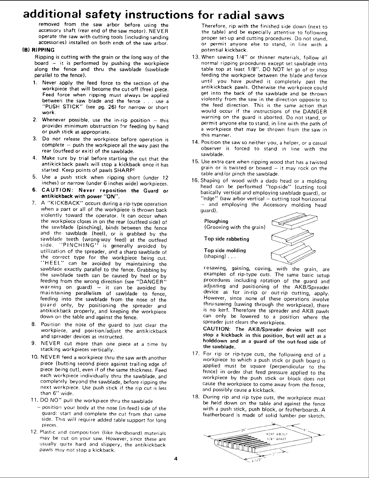
16. Shaping of wood with a dado head or a molding
head can be performed "top-side" (cutting tool
basically vertical and employing sawblade guard), or
"edge" (saw arbor vertical - cutting tool horizontal
- and employing the Accessory molding head
guard).
Ploughing
(Grooving with the grain)
Top side rabbeting
Top side molding
(shaping) ...
resawing, gaining, coving, with the grain, are
examples of rip-type cuts. The same basic setup
procedures including rotation of the guard and
adjusting and positioning of the AKB/Spreader
device as for in-rip or out-rip cutting, apply.
However, since none of these operations involve
thru-sawing (sawing through the workpiece), there
is no kerf. Therefore the spreader and AKB pawls
can only be lowered to a position where the
spreader just clears the workpiece.
CAUTION: The AKB/Spreader device will not
stop a kickback in this position, but will act as a
holddown and as a guard of the out-feed side of
the sawblade.
17.
For rip or rip-type cuts, the following end of a
workpiece to which a push stick or push board is
applied must be square (perpendicular to the
fence) in order that feed pressure applied to the
workpiece by the push stick or block does not
cause the workpiece to come away from the fence,
and possibly cause a kickback.
18.
During rip and rip type cuts, the workpiece must
be held clown on the table and against the fence
with a push stick, push block, or featherboards. A
featherboard is made of solid lumber per sketch.
(C)CROSSCUTTING
1. ALWAYSRETURNTHECARRIAGETOTHE
FULLREARWARDPOSITIONATCONCLUSION
OFEACHCROSSCUTTYPEOPERATION.Never
removeyourhandfromtheYokeHandleunlessthe
carriageisin thisposition.Otherwisethecutting
tool mayclimbup on theworkpieceandbe
propelledtowardyou.
2. Placeguardin horizontalpositionand adjust
antikickbackpawlstojustclearthetopofthefence
or workpiece,whicheverishigher.Thisprovides
additionalguarding.
3. NEVERgangcrosscut- liningupmorethanone
workpieceinfrontofthefence- stackedvertically,
or horizontallyoutwardonthetable- andthen
pullingsawthru:thebladecouldpickuponeor
morepiecesandcauseabindingorlossofcontrol
andpossibleinjury.
4. DonotpositiontheArmsotheoperationyouare
performingpermitsthe cuttingtool to extend
beyondtheedgesoftheTable.
5. Top-sidedadoingor moldingacrossthegrainare
examplesof crosscut-typecuts.Thesamebasic
procedures including positioning of the
AKB/Spreaderdeviceasforcrosscutting,apply.
(D)ACCESSORIES
1. Use only recommended accessories as listed on page
34.
2 Never operate this saw when equipped with a dado
head or molding head unless the molding head
guard is installed - see listing of recommended
accessories. The only exception is when "top-side"
dadoing or molding, when the sawblade guard must
be used. See detailed instructions that accompany
the dado head, molding head, and molding head
guard.
3.
The use of grinding wheels, abrasive or cut-off
wheels, or wire wheels, can be dangerous and is not
recommended. (Abrasive or cut-off wheels are used
to saw many different materials including metals,
stone, and glass.)
4,
Drill Chuck: Do not install or use any twist drill
larger than 1/2-inch in dia., or longer than 7 inches
in length or extending more than 6 inches beyond
the chuck jaws. Do not install or use any reduced
shank drill except of the spade type (1 inch dia. or
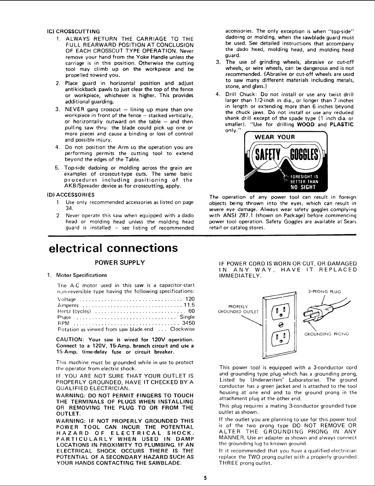
smaller). "Use for drilling WOOD and PLASTIC
only."
WEAR YOUR
The operation of any power tool can result in foreign
objects being thrown into the eyes, which can result in
severe eye damage. Always wear safety goggles complying
with ANSI Z87.1 (shown on Package) before commencing
power tool operation. Safety Goggles are available at Sears
retail or catalog stores.
electrical connections
POWER SUPPLY
1. Motor Specifications
The A-C motor used in this saw is a capacitor-start
non-reversible type having the following specifications:
Voltage ................................. 120
Amperes ................................ 11.5
Hertz (cycles) ............................. 60
Phase ................................ Single
PPM .................................. 3450
Potation as viewed from saw blade end . . . Clockwise
CAUTION: Your saw is wired for 120V operation.
Connect to a 120V, 15-Amp. branch circuit and use a
15-Amp. time-delay fuse or circuit breaker.
This machine must be grounded while in use to protect
the operator from electric shock.
IF YOU ARE NOT SURE THAT YOUR OUTLET IS
PROPERLY GROUNDED, HAVE IT CHECKED BY A
QUALIFIED ELECTRICIAN.
WARNING: DO NOT PERMIT FINGERS TO TOUCH
THE TERMINALS OF PLUGS WHEN INSTALLING
OR REMOVING THE PLUG TO OR FROM THE
OUTLET.
WARNING: IF NOT PROPERLY GROUNDED THIS
POWER TOOL CAN INCUR THE POTENTIAL
HAZARD OF ELECTRICAL SHOCK.
PARTICULARLY WHEN USED IN DAMP
LOCATIONS IN PROXIMITY TO PLUMBING. IF AN
ELECTRICAL SHOCK OCCURS THERE IS THE
POTENTIAL OF A SECONDARY HAZARD SUCH AS
YOUR HANDS CONTACTING THE SAWBLADE.
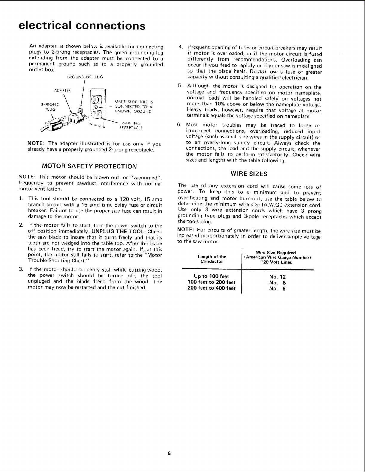
IF POWER CORD IS WORN OR CUT, OR DAMAGED
IN ANY WAY, HAVE IT REPLACED
IMMEDIATELY.
3-PRONG PLUG
PROPERLY
GROUNDED OUTLET
GROUNDING PRONG
This power tool is equipped with a 3-conductor cord
and grounding type plug which has a grounding prong,
Listed by Underwriters' Laboratories. The ground
conductor has a green jacket and is attached to the tool
housing at one end and to the ground prong in the
attachment plug at the other end.
This plug requires a mating 3-conductor grounded type
outlet as shown.
If the outlet you are planning to use for this power tool
is of the two prong type DO NOT REMOVE OR
ALTER THE GROUNDING PRONG IN ANY
MANNER. Use an adapter as shown and always connect
the grounding lug to known ground.
It it recommended that you have a qualified electrician
replace the TWO prong outlet with a properly grounded
THREE prong outlet.
electrical connections
An adapter as shown below is available for connecting
plugs to 2-prong receptacles. The green grounding lug
extending from the adapter must be connected to a
permanent ground such as to a properly grounded
outlet box.
GROUNDING LUG
3-PRONG '_ _ CONNECTED TO A
ADAPTER_/_\>,_l
PLUG __ ,_, KNOWN GROUND
MAKE SURE THIS IS
RECEPTACLE
NOTE: The adapter illustrated is for use only if you
already have a properly grounded 2-prong receptacle.
MOTOR SAFETY PROTECTION
NOTE: This motor should be blown out, or "vacuumed",
frequently to prevent sawdust interference with normal
motor ventilation.
1.
This tool should be connected to a 120 volt, 15 amp
branch circuit with a 15 amp time delay fuse or circuit
breaker. Failure to use the proper size fuse can result in
damage to the motor.
2.
If the motor fails to start, turn the power switch to the
off position immediately. UNPLUG THE TOOL. Check
the saw blade to insure that it turns freely and that its
teeth are not wedged into the table top. After the blade
has been freed, try to start the motor again. If, at this
point, the motor still fails to start, refer to the "Motor
Trouble-Shooting Chart."
3.
If the motor should suddenly stall while cutting wood,
the power switch should be turned off, the tool
unpluged and the blade freed from the wood. The
motor may now be restarted and the cut finished.
4.
Frequent opening of fuses or circuit breakers may result
if motor is overloaded, or if the motor circuit is fused
differently from recommendations. Overloading can
occur if you feed to rapidly or if your saw is misaligned
so that the blade heels. Do not use a fuse of greater
capacity without consulting a qualified electrician.
Although the motor is designed for operation on the
voltage and frequency specified on motor nameplate,
normal loads will be handled safely/ on voltages not
more than 10% above or below the nameplate voltage.
Heavy loads, however, require that voltage at motor
terminals equals the voltage specified on nameplate.
Most motor troubles may be traced to loose or
incorrect connections, overloading, reduced input
voltage (such as small size wires in the supply circuit) or
to an overly-long supply circuit. Always check the
connections, the load and the supply circuit, whenever
the motor fails to perform satisfactorily. Check wire
sizes and lengths with the table following.
WIRE SIZES
The use of any extension cord will cause some loss of
power. To keep this to a minimum and to prevent
over-heating and motor burn-out, use the table below to
determine the minimum wire size (A.W.G.) extension cord.
Use only 3 wire extension cords which have 3 prong
grounding type plugs and 3-pole receptacles which accept
the tools plug.
NOTE: For circuits of greater length, the wire size must be
increased proportionately in order to deliver ample voltage
to the saw motor.
Length of the
Conductor
Up to 100 feet
100 feet to 200 feet
200 feet to 400 feet
Wire Size Required
(American Wire Gauge Number)
120 Volt Lines
No. 12
No. 8
No. 6
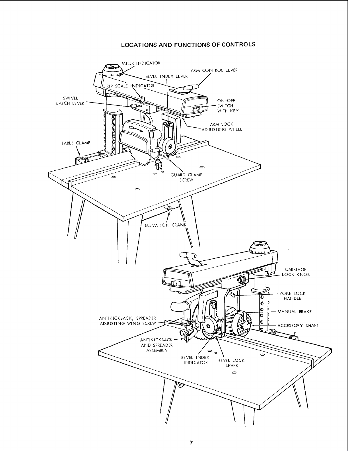
LOCATIONS AND FUNCTIONS OF CONTROLS
MITER INDICATOR
ARM CONTROL LEVER
BEVEL INDEX LEVER
RIP SCALE INDICATOR
SWIVEL
L_ATCH LEVER
TABLE CLAMP
ON-OFF
SWITCH
WITH KEY
LOCK
NG WHEEL
GUARD CLAMP
SCREW
ELEVATION CRANK
\
ANTIKICKBACK_ SPREADER
ADJUSTING WING SCREW
ANTIKtCKBACK
AND SPREADER
ASSEMBLY
BEVEL INDEX
INDICATOR
CARRIAGE
LOCK KNOB
LOCK
HANDLE
MANUAL BRAKE
SHAFT
BEVEL LOCK
LEVER
7
CONTENTS
Guarantee .................................... 2
General Safety Instructions for Power Tools ......... 2
Additional Safety Instructions for Radial Saws ....... 3
Electrical Connections .......................... 5
Assembly and Alignment ........................ 8
Unpacking and Preassembly ..................... 8
Alignment Procedure ......................... 11
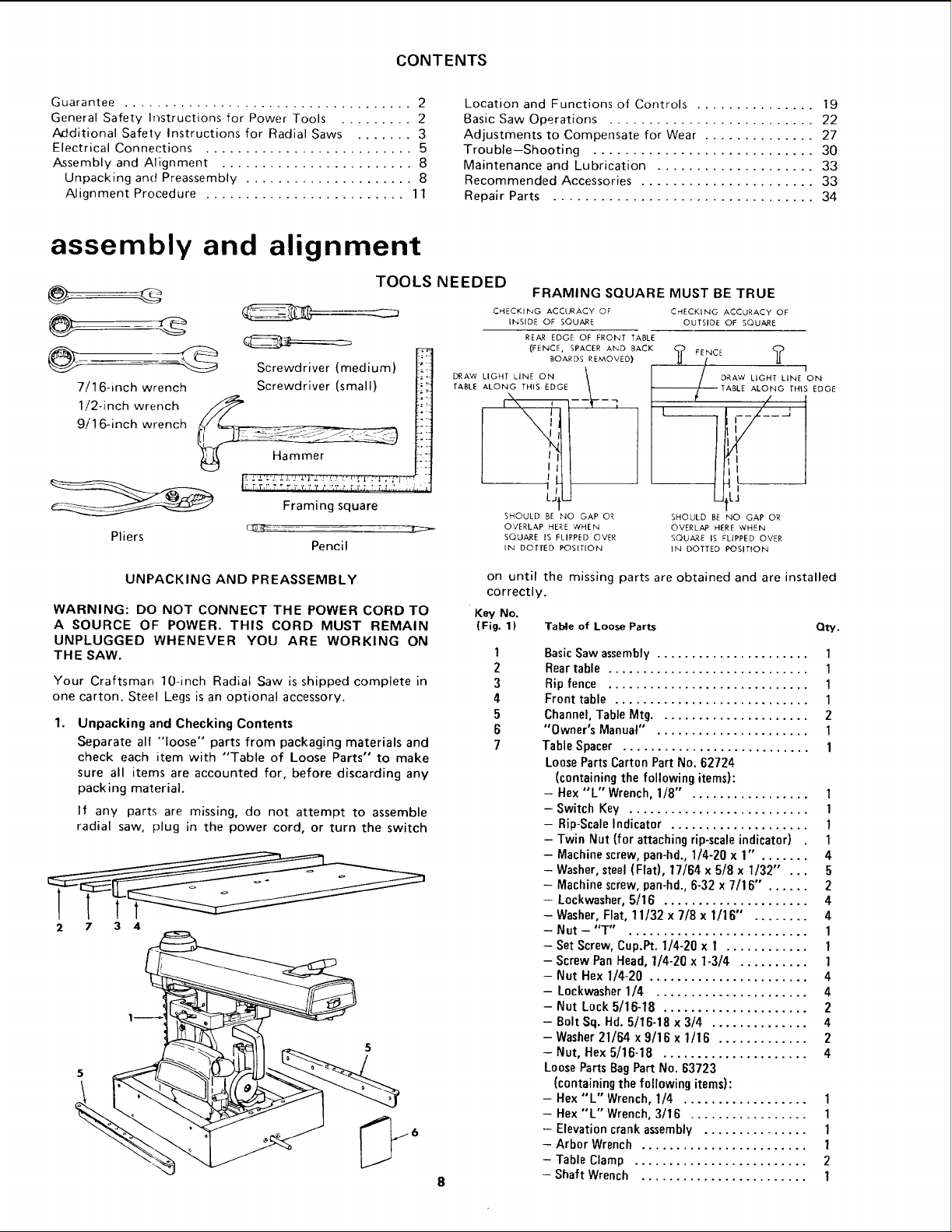
assembly and alignment
TOOLS NEEDED
Screwdriver (medium)
9/'16-inch wrench
7/11/2.in ch6-i nChwrenchWrench_Screwdriver (small)
Pliers
Hammer
Framing square
Pencil
Location and Functions of Controls ............... 19
Basic Saw Operations .......................... 22
Adjustments to Compensate for Wear .............. 27
Trouble-Shooting ............................ 30
Maintenance and Lubrication .................... 33
Recommended Accessories ...................... 33
Repair Parts ................................. 34
FRAMING SQUARE MUST BE TRUE
CHECKING ACCURACY OF C_ECKING ACCURACY OF
INSIDE OF SQUARE OUTSIDE OF SQUARE
REAR EDGE OF FRONT TABLE
(FENCE, SPACER AND BACK _-_ FENCE <_
BOARDS REMOVED) ]J / Jl
DRAW
LIGHT LINE ON \ / DRAW LIGHT LINE ON
TABLE
ALONG THIS EDGE "_ --/_'----TABLE ALONG THIS EDGE
I\\ _ I--_-- q f / ,
f
L- tu utLJ
SHOULD BE NO GAP OR SHOULD BE NO GAP OR
OVERL&P HERE 'WHEN OVERLAP HERE WHEN
SQUARE IS FLIPPED OVER SQUARE IS FLIPPED OVER
IN DOTTED POSITION IN DOTTED POSITION
I
UNPACKING AND PREASSEMBLY
WARNING: DO NOT CONNECT THE POWER CORD TO
A SOURCE OF POWER. THIS CORD MUST REMAIN
UNPLUGGED WHENEVER YOU ARE WORKING ON
THE SAW.
Your Craftsman 10-inch Radial Saw is shipped complete in
one carton. Steel Legs is an optional accessory.
1.
Unpacking and Checking Contents
Separate all "loose" parts from packaging materials and
check each item with "Table of Loose Parts" to make
sure all items are accounted for, before discarding any
packing material.
If any parts are missing, do not attempt to assemble
radial saw, plug in the power cord, or turn the switch
2 7 3 4
on until the missing parts are obtained and are installed
correctly.
Key No,
(Fig. 1) Table of Loose Parts Qty.
1
2
3
4
5
6
7
BasicSaw assembly...................... 1
Reartable ............................. 1
Ripfence ............................. 1
Front table ............................ 1
Channel,TableMtg...................... 2
"Owner's Manual" . ..................... 1
TableSpacer ........................... 1
LoosePartsCarton Part No. 62724
(containingthe following items):
- Hex"L" Wrench,1/8" . ................ 1
- Switch Key .......................... 1
- Rip-ScaleIndicator .................... 1
- Twin Nut (for attachingrip-scaleindicator) 1
- Machinescrew,pan-hd.,1/4-20x 1" . ...... 4
- Washer,steel(Flat), 17/64 x 5/8 x 1/32" ... 5
- Machinescrew,pan-hd.,6-32 x 7/16" . ..... 2
- Lockwasher,5/16 ..................... 4
- Washer,Flat, 11/32 x 7/8 x 1/16" . ....... 4
- Nut-"T" . ......................... 1
- SetScrew,Cup.Pt. 1/4-20 x 1 ............ 1
- ScrewPan Head,1/4-20 x 1-3/4 .......... 1
- Nut Hex 1/4-20 ....................... 4
- Lockwasher1/4 ...................... 4
- Nut Lock 5/16-18 ..................... 2
- Bolt Sq. Hd.5/16-18 x 3/4 .............. 4
- Washer21/64 x 9/16 x 1/16 ............. 2
- Nut, Hex5/16-18 ..................... 4
LoosePartsBagPart No. 63723
(containingthe followingitems):
- Hex"L" Wrench,1/4 .................. 1
- Hex"L" Wrench,3/16 ................. 1
- Elevationcrankassembly ............... 1
- Arbor Wrench ........................ 1
- TableClamp ......................... 2
- Shaft Wrench ........................ 1
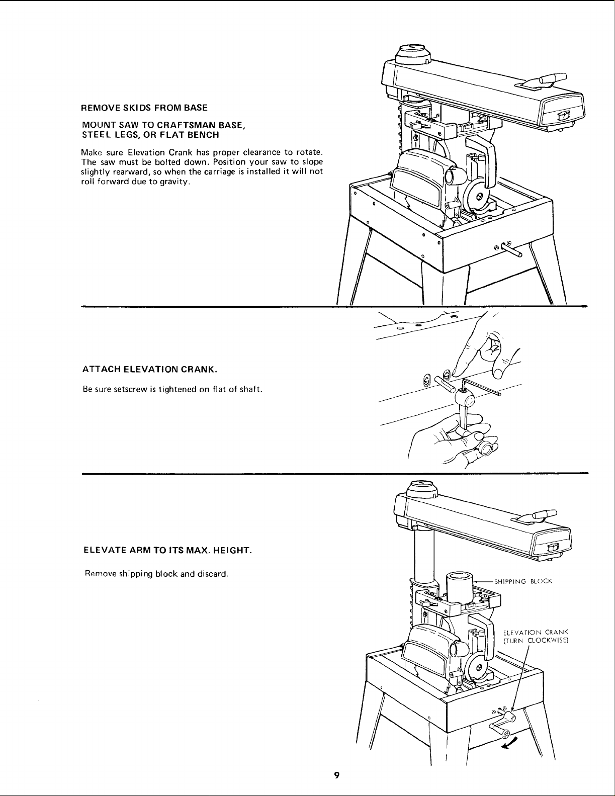
REMOVE SKIDS FROM BASE
MOUNT SAW TO CRAFTSMAN BASE,
STEEL LEGS, OR FLAT BENCH
Make sure Elevation Crank has proper clearance to rotate.
The saw must be bolted down. Position your saw to slope
slightly rearward, so when the carriage is installed it will not
roll forward due to gravity.
ATTACH ELEVATION CRANK.
Be sure setscrew is tightened on flat of shaft.
I
ELEVATE ARM TO ITS MAX. HEIGHT.
Remove shipping block and discard.
PPING BLOCK
ELEVATION CRANK
(TURIN CLOCKWISE)
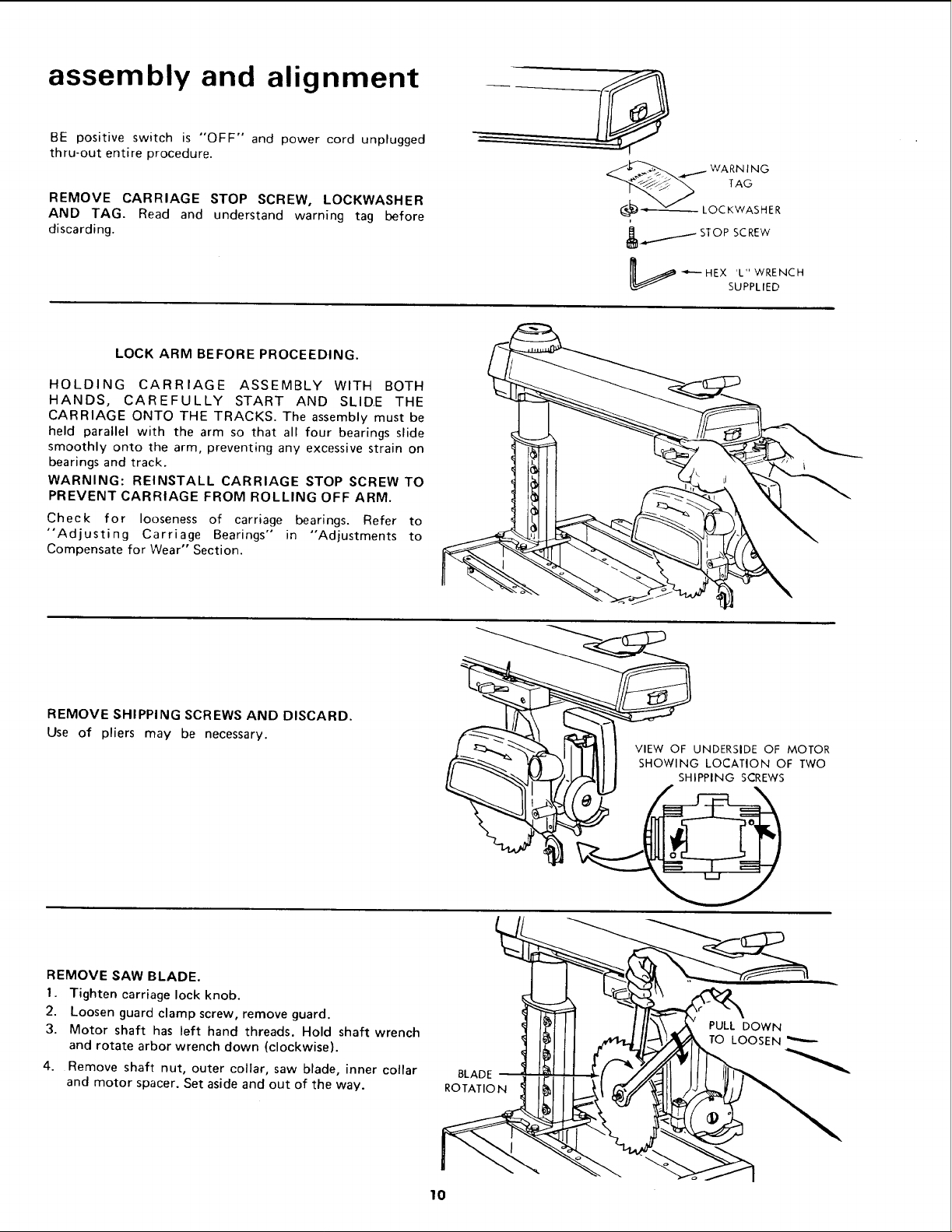
assembly and alignment
BE positive switch is "OFF" and power cord unplugged
thru-out entire procedure.
REMOVE CARRIAGE STOP SCREW, LOCKWASHER
AND TAG. Read and understand warning tag before
discarding.
_J__._ WARN ING
TAG
_:_ -.,_-----_,--- LOCKWASHER
i_...._./STOP SCREW
LOCK ARM BEFORE PROCEEDING.
HOLDING CARRIAGE ASSEMBLY WITH BOTH
HANDS, CAREFULLY START AND SLIDE THE
CARRIAGE ONTO THE TRACKS. The assembly must be
held parallel with the arm so that all four bearings slide
smoothly onto the arm, preventing any excessive strain on
bearings and track.
WARNING: REINSTALL CARRIAGE STOP SCREW TO
PREVENT CARRIAGE FROM ROLLING OFF ARM.
Check for looseness of carriage bearings. Refer to
"Adjusting Carriage Bearings" in "Adjustments to
Compensate for Wear" Section.
REMOVE SHIPPING SCREWS AND DISCARD.
Use of pliers may be necessary.
L_ "_'-'- HEX 'L" WRENCH
VIEW OF UNDERSIDE OF MOTOR
SHOWING LOCATION OF TWO
SHIPPING SCREWS
SUPPLIED
REMOVE SAW BLADE.
1. Tighten carriage lock knob.
2. Loosen guard clamp screw, remove guard.
3. Motor shaft has left hand threads. Hold shaft wrench
and rotate arbor wrench down (clockwise).
4. Remove shaft nut, outer collar, saw blade, inner collar
and motor spacer. Set aside and out of the way.
PULL DOWN
TO LOOSEN
BLADE
ROTATION
I0
ALIGNMENT PROCEDURE
IMPORTANT:
IN ORDER TO OBTAIN MAXIMUM CUTTING
ACCURACY, THE FOLLOWING SIX STEPS
MUST BE CAREFULLY FOLLOWED.
BECOME THOROUGHLY FAMILIAR WITH
THESE STEPS SO THAT YOU CAN ALWAYS
MAINTAIN YOUR SAW IN PROPER
ALIGNMENT. THE ACCURACY OF EACH
ADJUSTMENT IS ALWAYS DEPENDENT
UPON THE ACCURA C YOF THE PRECEDING
ADJUSTMENT.
After following the 6 step assembly and alignment
procedure and the Basic Saw operation section refer to
Trouble Shooting section if any difficulty is experienced
when performing any sawing operation.
STEP ON E
NOTE: The following adjustment, performed properly, will
result in the work table being parallel to the arm.
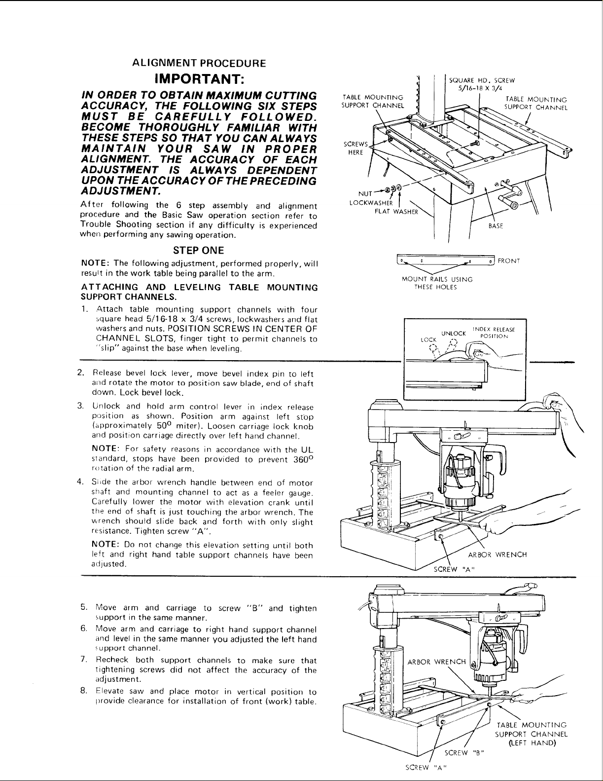
ATTACHING AND LEVELING TABLE MOUNTING
SUPPORT CHANNE LS.
1. Attach table mounting support channels with four
square head 5/16-18 x 3/4 screws, Iockwashers and flat
washers and nuts. POSITION SCREWS IN CENTER OF
CHANNEL SLOTS, finger tight to permit channels to
"slip" against the base when leveling.
TABLE MOUNTING
SUPPORT CHANNEL
\
SCREWS
HERE
LOCKWASHER /
FLAT WASHER
SQUARE HD. SCREW
s/16-1B x 3/4
/__ FRONT
MOUNT RAILS USING
THESE HOLES
UNLOCK POSITION
LOCK i'_
TABLE MOUNTING
SUPPORT CHANNEL
BASE
iNDEX RELEASE
2.
Release bevel lock lever, move bevel index pin to left
and rotate the motor to position saw blade, end of shaft
down. Lock bevel lock.
3.
Unlock and hold arm control lever in index release
position as shown. Position arm against left st'op
(approximately 50 ° miter). Loosen carriage lock knob
and position carriage directly over left hand channel.
NOTE: For safety reasons in accordance with the UL
standard, stops have been provided to prevent 360 °
r_tation of the radial arm.
4.
S;ide the arbor wrench handle between end of motor
shaft and mounting channel to act as a feeler gauge.
Carefully lower the motor with elevation crank until
the end of shaft is just touching the arbor wrench. The
wrench should slide back and forth with only slight
resistance. Tighten screw "'A".
NOTE: Do not change this elevation setting until both
left and right hand table support channels have been
adjusted.
5. Move arm and carriage to screw "B" and tighten
support in the same manner.
6. Move arm and carriage to right hand support channel
and level in the same manner you adjusted the left hand
support channel.
7. Recheck both support channels to make sure that
tightening screws did not affect the accuracy of the
adjustment.
8. Elevate saw and place motor in vertical position to
provide clearance for installation of front (work) table.
_J
ARBOR WRENCH
SCREW "A"
SCREW "A"
TABLE MOUNTING
SUPPORT CHANNEL
(LEFT HAND)
SCREW "B"
assembly and alignment
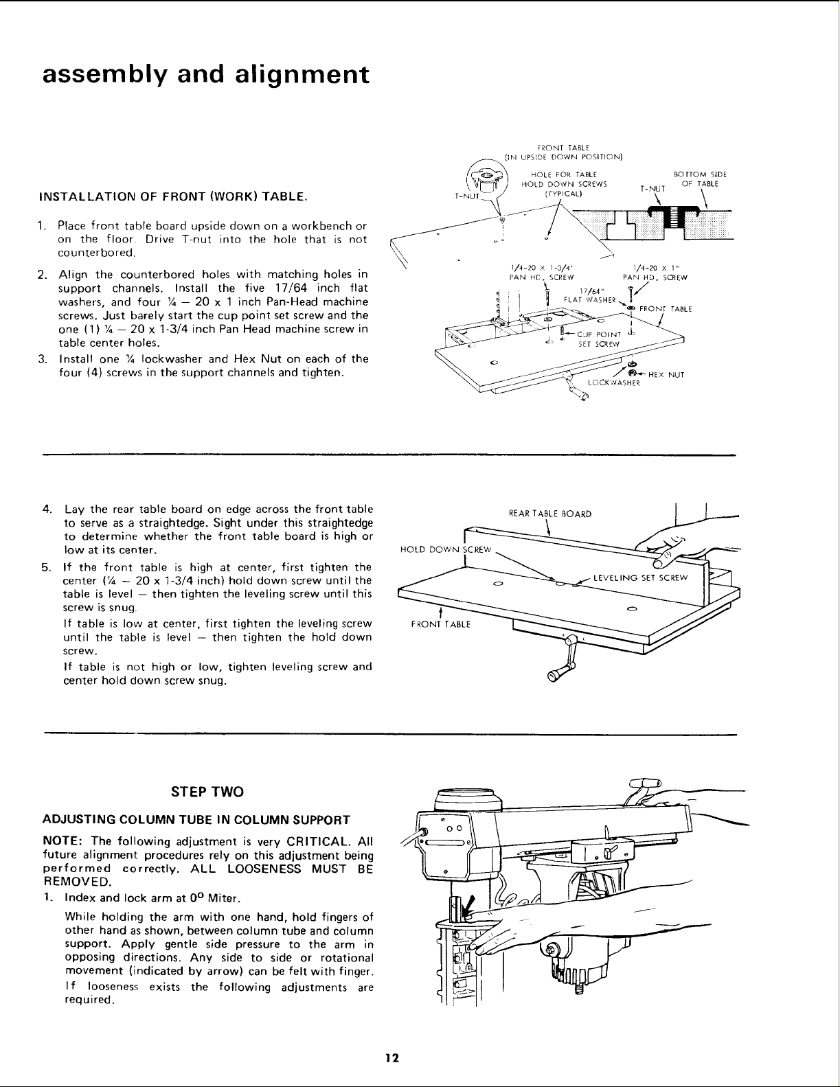
INSTALLATION OF FRONT (WORK) TABLE.
1.
Place front table board upside down on a workbench or
on the floor Drive T-nut into the hole that is not
counterbored.
2. Align the counterbored holes with matching holes in
support channels. Install the five 17/64 inch flat
washers, and four ¼- 20 x 1 inch Pan-Head machine
screws. Just barely start the cup point set screw and the
one (1) ¼ - 20 x 1-3/4 inch Pan Head machine screw in
table center holes.
3. Install one ¼ Iockwasher and Hex Nut on each of the
four (4) screws in the support channels and tighten.
FRONT TABLE
IN UPSIDE DOWN POSITION)
HOLE FOR TABLE BOTTOM S,DE
"_\ k_J"_ _._/! HOLD DOWN SCREWS T-NUT OF TABLE
T-NUT /" (TYPICAL) _
_ 1/4-20 X°1-3/4 ' _ 1/4-20 X 1"
PAN HE. SCREW PAN HD. SCREW
i FLAT WASHER
IL_ONT TABLE
LOCKWASHER
HEX NUT
4.
Lay the rear table board on edge across the front table
to serve as a straightedge. Sight under this straightedge
to determine whether the front table board is high or
low at its center.
5.
If the front table is high at center, first tighten the
center (¼ -- 20 x 1-3/4 inch) hold down screw until the
table is level -- then tighten the leveling screw until this
screw is snug
If table is low at center, first tighten the leveling screw
until the table is level - then tighten the hold down
screw.
If table is not high or low, tighten leveling screw and
center hold down screw snug.
STEP TWO
ADJUSTING COLUMN TUBE IN COLUMN SUPPORT
NOTE: The following adjustment is very CRITICAL. All
future alignment procedures rely on this adjustment being
performed correctly. ALL LOOSENESS MUST BE
REMOVED.
1. Index and lock arm at 0 ° Miter.
While holding the arm with one hand, hold fingers of
other hand as shown, between column tube and column
support. Apply gentle side pressure to the arm in
opposing directions. Any side to side or rotational
movement (indicated by arrow) can be felt with finger.
If looseness exists the following adjustments are
req u ired.
FRONT TABLE
12
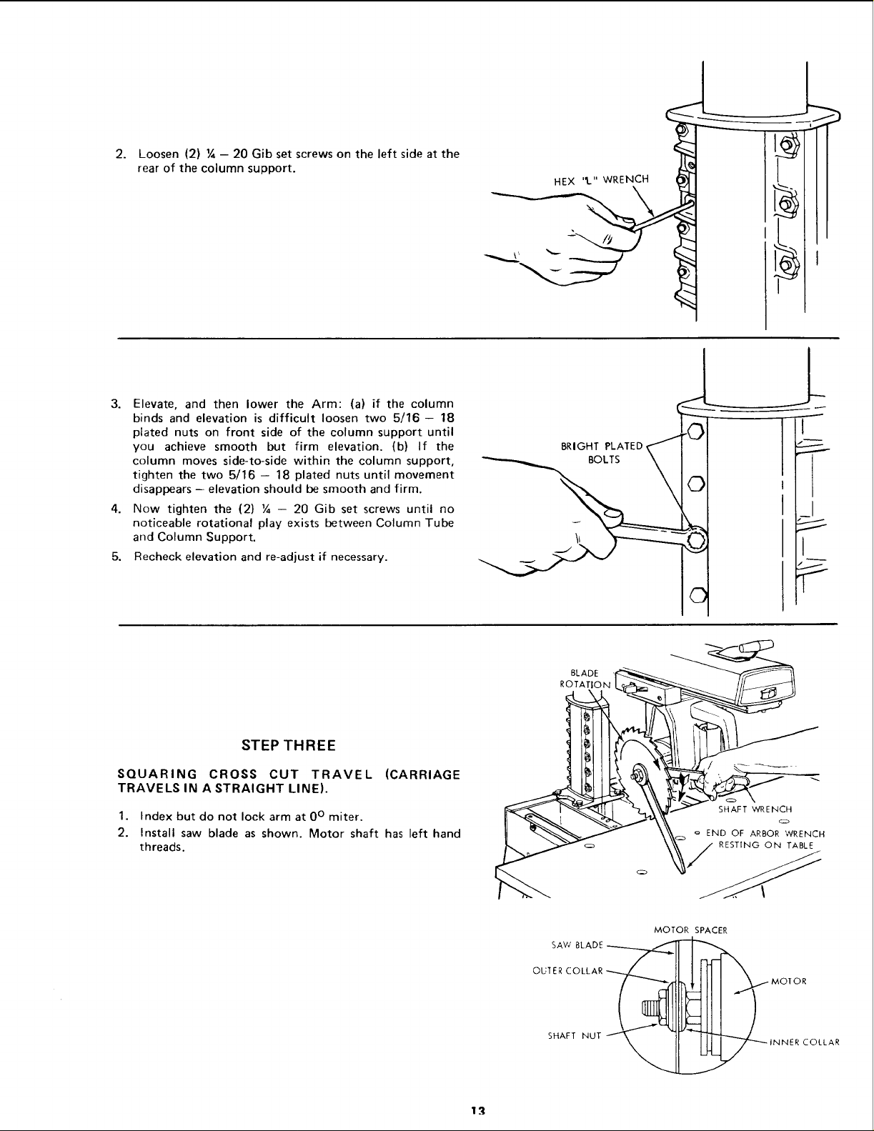
2. Loosen (2) ¼ - 20 Gib set screws on the left side at the
rear of the column support.
3. Elevate, and then lower the Arm: (a) if the column
binds and elevation is difficult loosen two 5/16- 18
plated nuts on front side of the column support until
you achieve smooth but firm elevation. (b) If the
column moves side-to-side within the column support,
tighten the two 5/16 - 18 plated nuts until movement
disappears -- elevation should be smooth and firm.
4. Now tighten the (2) ¼ - 20 Gib set screws until no
noticeable rotational play exists between Column Tube
and Column Support.
5. Recheck elevation and re-adjust if necessary.
->
L
T-
8R,O.T LA,Eo<JT
BOLTS \ I
©
_I
STEP THREE
SQUARING CROSS CUT TRAVEL (CARRIAGE
TRAVELS IN A STRAIGHT LINE).
1. Index but do not lock arm at 0 ° miter.
2. Install saw blade as shown. Motor shaft has left hand
threads.
SAW BLADE
SHAFT NUT
_,:_ ° END OF ARBOR WRENCH
%/ RESTING ON TABLE
MOTOR SPACER
)IOR
ER COLLAR
assembly and alignment
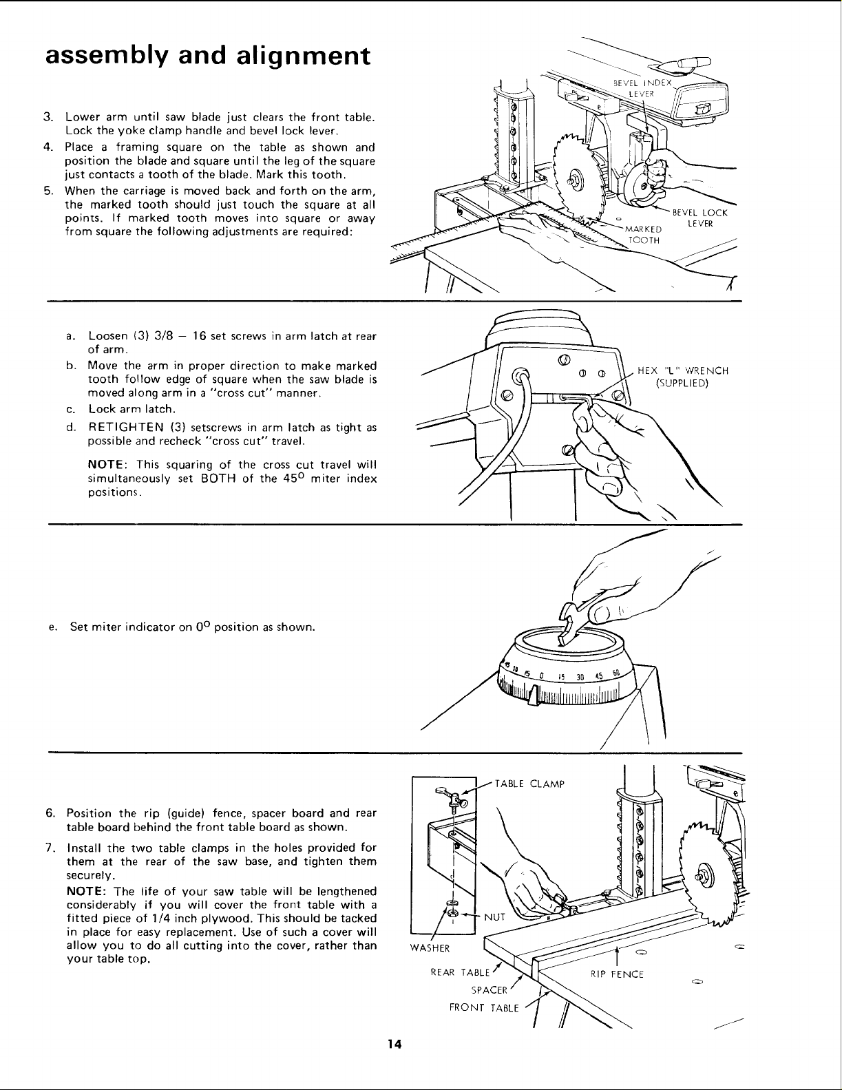
3. Lower arm until saw blade just clears the front table.
Lock the yoke clamp handle and bevel lock lever.
4. Place a framing square on the table as shown and
position the blade and square until the leg of the square
just contacts a tooth of the blade. Mark this tooth.
5. When the carriage is moved back and forth on the arm,
the marked tooth should just touch the square at all
points. If marked tooth moves into square or away
from square the following adjustments are required:
a. Loosen (3) 3/8 - 16 set screws in arm latch at rear
of arm.
b. Move the arm in proper direction to make marked
tooth follow edge of square when the saw blade is
moved along arm in a "cross cut" manner.
c. Lock arm latch.
d. RETIGHTEN (3) setscrews in arm latch as tight as
possible and recheck "cross cut" travel.
NOTE: This squaring of the cross cut travel will
simultaneously set BOTH of the 45 ° miter index
positions.
BEVEL LOCK
LEVER
TOOTH
HEX "L" vVRENCH
(SUPPLIED)
e.
Set miter indicator on 0 ° position as shown.
6.
Position the rip (guide) fence, spacer board and rear
table board behind the front table board as shown.
7.
Install the two table clamps in the holes provided for
them at the rear of the saw base, and tighten them
securely.
NOTE: The life of your saw table will be lengthened
considerably if you will cover the front table with a
fitted piece of 1/4 inch plywood. This should be tacked
in place for easy replacement. Use of such a cover will
allow you to do all cutting into the cover, rather than
your table top.
WASHER
REAR TABLE
TABLE CLAMP
RIP FENCE
FRONT TABLE
'14
 Loading...