

Craftsman 113.12171 Installation & Repair Manual
Sears
owners
manual
MODEL
No.
113.12171
CAUTION:
READ
INSTRUCTIONS
and
SAFETY
PRECAUTIONS
carefully
DO NOT
DESTROY
SAVE FOR
FUTURE
REFERENCE
CRAFTSMAN
I
H.P. CAPACITOR START
A.C. MOTOR
•
installation
•
repair parts
SEARS, ROEBUCK AND CO., Chicago, II. 60684 U.S.A.
and SIMPSONS-SEARS LIMITED, Toronto
Part No. 64152
Printed in U. S. A.
VMGMSGGSSSMSSGSGVSSMSSGSGGSMSSMSSSMSSSV
FULL ONE YEAR WARRANTY ON CRAFTSMAN MOTORS
If this Craftsman motor fails
to
give complete satisfaction within one year from the date of purchase, return
it to the nearest Sears store throughout the United States and Sears will replace it free of charge.
This warranty gives you specific legal rights, and you may also have other rights which vary from state to
state.
SEARS, ROEBUCK AND CO.
BSC 41-3
SEARS TOWER
(,(,/,/,N(RomommuRouommomonyiono,ha
INSTALLATION, CONNECTION AND MAINTENANCE INSTRUCTIONS
FOR
CRAFTSMAN MOTOR - MODEL NO. 113.12171
EXTRA SAFETY PRECAUTIONS: Motor must be properly grounded. (See figure
4).
Do
not operate motor with key and key clip loose on shaft. Keep hands and clothing away
from moving parts. Mount shaft guard assembly over shaft extension not being used.
CHICAGO, IL 60684
This Craftsman Motor is of the capacitor start type
designed for use on a single-phase, 60-cycle, alternatingcurrent supply of 115 volts, with a simple means of
reversing the direction of rotation provided. The motor
may be operated in any position.
INSTALLING THE MOTOR
1. This motor was given a thorough electrical and
mechanical inspection before it was shipped from the
factory. In order to make sure that no damage has
occurred during shipment, the following check pro-
cedure should be made before mounting the motor in
the particular application for which it was purchased.
a.
Remove key and key clip from shaft.
b.
Rotate the shaft with the fingers to make sure it
turns freely and smoothly.
c.
Clamp motor base to work bench or table. Insure
motor is properly grounded. Do not touch motor
while it is energized. Temporarily connect motor
to the proper voltage supply in accordance with
instructions under "Connecting the Motor".
When
energized, the motor should operate with only a
small amount of electrical "hum" and very low
bearing noise.
d.
Notice direction of shaft rotation to make sure it
is correct for the equipment to be driven. If direction of rotation is not correct, reverse rotation
as outlined in instructions listed under
"Connect-
ing the Motor".
2.
Disconnect the motor from temporary power source
and mount it in the application for which it was purchased.
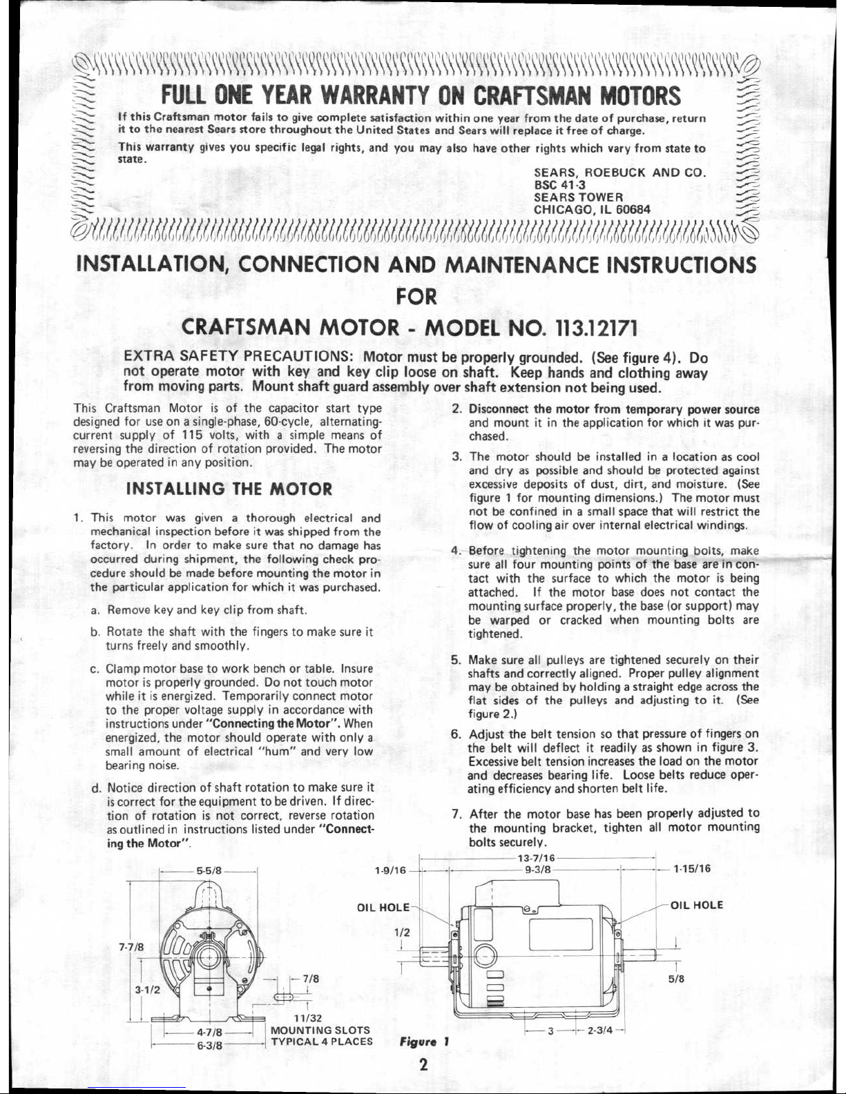
3.
The motor should be installed in a location as cool
and dry as possible and should be protected against
excessive deposits of dust, dirt, and moisture. (See
figure
1
for mounting dimensions.) The motor must
not be confined in a small space that will restrict the
flow of cooling air over internal electrical windings.
4.
Before tightening the motor mounting bolts, make
sure all four mounting points of the base are
in con-
tact
with the surface to which the motor is being
attached. If the motor base does not contact the
mounting surface properly, the base (or support) may
be warped or cracked when mounting bolts are
tightened.
5.
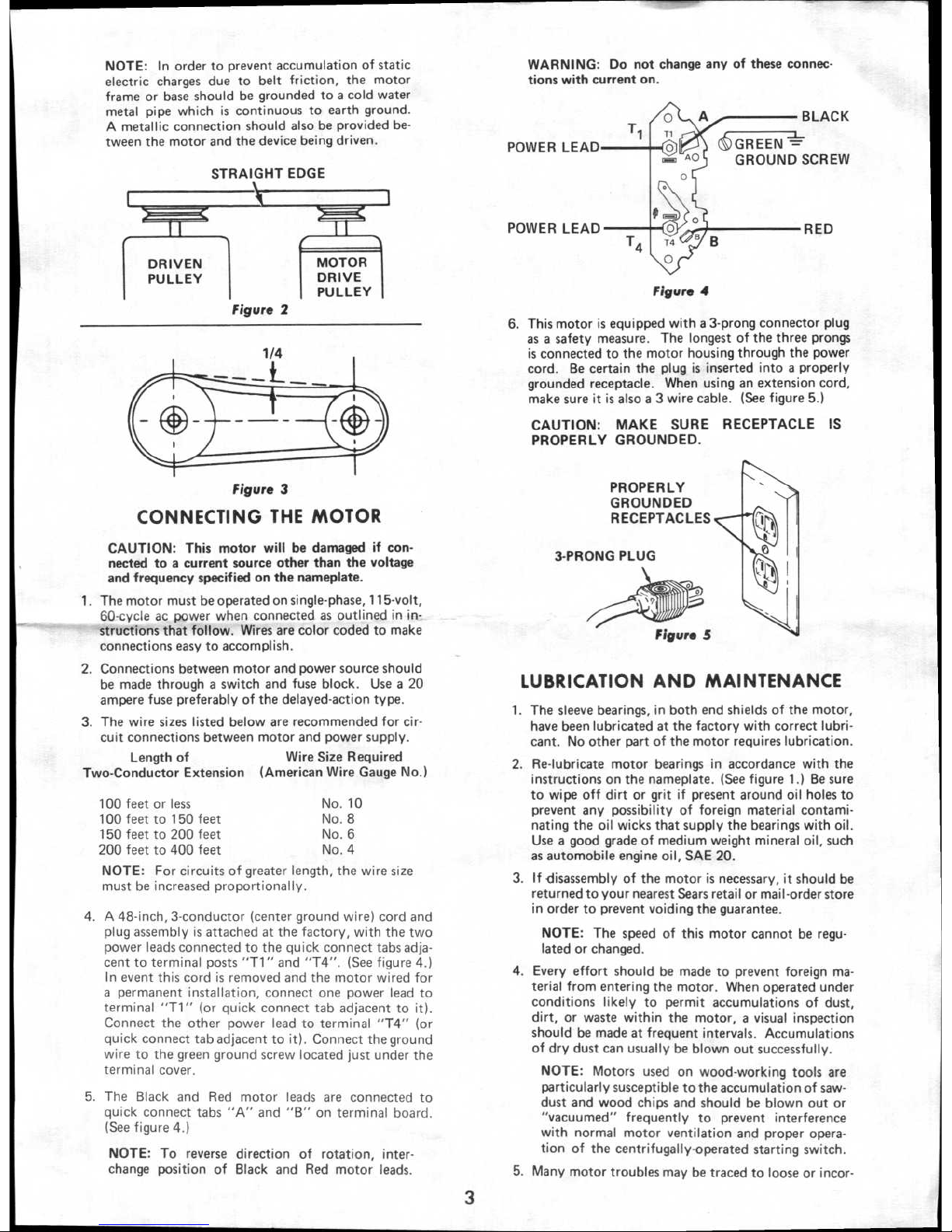
Make sure all pulleys are tightened securely on their
shafts and correctly aligned. Proper pulley alignment
may be obtained by holding a straight edge across the
flat sides of the pulleys and adjusting to it. (See
figure 2.)
6.
Adjust the belt tension so that pressure of fingers on
the belt will deflect it readily as shown in figure 3.
Excessive belt tension increases the load on the motor
and decreases bearing life. Loose belts reduce operating efficiency and shorten belt life.
7.
After the motor base has been properly adjusted to
the mounting bracket, tighten all motor mounting
bolts securely.
13-7/16
9 3/8
1 15/16
11/32
MOUNTING SLOTS
TYPICAL 4 PLACES
Figure 1
2
MOTOR
DRIVE
PULLEY
DRIVEN
PULLEY
PROPERLY
GROUNDED
RECEPTACLES
3-PRONG PLUG
Figure 5
BLACK
)GREEN
GROUND SCREW
POWER LEAD
POWER LEAD
RED
Figure
4
NOTE: In order to prevent accumulation of static
electric charges due to belt friction, the motor
frame or base should be grounded to a cold water
metal pipe which is continuous to earth ground.
A metallic connection should also be provided between the motor and the device being driven.
STRAIGHT EDGE
Figure 2
Figure
3
CONNECTING THE MOTOR
CAUTION: This motor will be damaged if connected to a current source other than the voltage
and frequency specified on the nameplate.
1.
The motor must be operated on single-phase, 115-volt,
60-cycle ac power when connected as outlined in instructions that follow. Wires are color coded to make
connections easy to accomplish.
2.
Connections between motor and power source should
be made through a switch and fuse block. Use a 20
ampere fuse preferably of the delayed-action type.
3.
The wire sizes listed below are recommended for circuit connections between motor and power supply.
Length of
Wire Size Required
Two-Conductor Extension (American Wire Gauge No.)
100
feet or less
No.
10
100
feet to 150 feet
No. 8
150 feet to 200 feet
No. 6
200 feet to 400 feet
No. 4
NOTE: For circuits of greater length, the
wire size
must be increased proportionally.
4.
A 48-inch, 3-conductor (center ground wire) cord and
plug assembly is attached at the factory, with the two
power leads connected to the quick connect tabs adjacent to terminal posts
"T1"
and
"T4".
(See figure
4.)
In
event this cord is removed and the motor wired for
a permanent installation, connect one power lead to
terminal
"T1"
(or quick connect tab adjacent to it).
Connect the other power lead to terminal
"T4" (or
quick
connect tab adjacent to it). Connect the ground
wire to the green ground screw located just under the
terminal cover.
5.
The Black and Red motor leads are connected to
quick connect tabs "A" and
"B" on
terminal board.
(See figure 4.)
NOTE: To reverse direction of rotation, interchange position of Black and Red motor leads.
WARNING: Do not change any of these connections with current on.
6. This motor is equipped with a 3-prong connector plug
as a safety measure. The longest of the three prongs
is connected to the motor housing through the power
cord. Be certain the plug is inserted into a properly
grounded receptacle. When using an extension cord,
make sure it is also a 3 wire cable. (See figure 5.)
CAUTION: MAKE SURE RECEPTACLE IS
PROPERLY GROUNDED.
LUBRICATION AND MAINTENANCE
1.
The sleeve bearings, in both end shields of the motor,
have been lubricated at the factory with correct lubricant. No other part of the motor requires lubrication.
2.
Re-lubricate motor bearings in accordance with the
instructions on the nameplate. (See figure 1.) Be sure
to wipe off dirt or grit if present around oil holes to
prevent any possibility of foreign material contaminating the oil wicks that supply the bearings with oil.
Use a good grade of medium weight mineral oil, such
as automobile engine oil, SAE 20.
3.
If disassembly of the motor is necessary, it should be
returned to your nearest Sears retail or mail-order store
in order to prevent voiding the guarantee.
NOTE: The speed of this motor cannot be regulated or changed.
4.
Every effort should be made to prevent foreign material from entering the motor. When operated under
conditions likely to permit accumulations of dust,
dirt, or waste within the motor, a visual inspection
should be made at frequent intervals. Accumulations
of dry dust can usually be blown out successfully.
NOTE: Motors used on wood-working tools are
particularly susceptible to the accumulation of saw-
dust and wood chips and should be blown out or
"vacuumed" frequently to prevent interference
with normal motor ventilation and proper operation of the centrifugally-operated starting switch.
5.
Many motor troubles may be traced to loose or incor-
3
 Loading...