

Page 1

Operator's nu
ZTS 7500
Zero-Turn Rear Engine Riders with
Electric Start
Model No.
107.27788 (20HP Kohler Engine with 44" Mower)
107.27790 (24HP Bdggs & Stratton Engine with 50" Mower)
CAUTmON: Before using this product, read
the manuaWand follow all its Safety Rules
and Operating Instructions.
Sears, Roebuck and Co., Hoffman Estates, IL 60179 U.S.A.
Visit our Craftsman website: www, sears,com/craftsman
For answers to your questions about this
product, call:
1-800-659-5917
Sears Craftsman HeJp Line
5 am o5 pm, Mort oSat
Nota: Una traducci6n en espa_oU de este ManuaU
del Operador puede encontrarse en la pAgina 35.
TP 899-4448-03-CZ-C
1734211
Revision 03
Page 2
Nota: Una traducci6n en espa_oU de este ManuaU del Operador puede encontrarse en la pb@na 35.
Warranty Statement ..................................................... 2
Safety RuJes & information ......................................... 3
identification Numbers ................................................ 8
Optional Accessories .................................................. 8
Literature Package Contents ...................................... 8
Pre-Operation ............................................................... 9
Operation .................................................................... 10
Maintenance ............................................................... 17
Storage ....................................................................... 32
Specifications ............................................................ 32
TroubJeshooting ......................................................... 33
Spanish Operator's Manua! ...................................... 35
Repair Parts ......................................................... PTS-1
Hardware & Torque Specifications ................... PTS-44
Repair Protection Agreement ........ mnside Back Cover
Service Numbers ........................................ Back Cover
Service & Adjustments ............................................. 28
NOTE." In this manual 'left"and "right"are referred to as seen from the operating position.
LiMiTED WARRANTY ON CRAFTSMAN RiDiNG EQUIPMENT
For two (2) years from the date of purchase, if this Craftsman riding equipment is maintained, lubricated and tuned up
according to the instructions in the owner's manual, Sears will repair or replace free of charge any parts that are
found to be defective in material or workmanship according to the guidelines of coverage listed below, Sears will also
provide free labor for these applicable warrantied parts for the two fuji years, During the first 30 days of purchase,
there wiii be no charges to service the product at your home for issues covered by this warranty, (See exclusions
below), For your convenience, iN HOME warranty service wiii still be available after the first 30 days of purchase, but
a trip charge will apply, This charge will be waived if the Craftsman product is dropped off at an authorized Sears
location, For the nearest authorized Sears location, please call 1-800-MY-HOME, This warranty applies only while this
product is within the United States,
THiS WARRANTY DOES NOT COVER:
Expendable items which become worn during normal
use, including but not limited to blades, spark plugs,
air cleaners, belts, and oil filters,
o Standard maintenance servicing, oil changes, or
tune-ups,
Tire replacement or repair caused by punctures from
Repairs necessary because of operator negligence,
including but not limited to, electrical and mechanical
damage caused by improper storage, failure to use
the proper grade and amount of engine oil, failure to
keep the deck clear of flammable debris, or failure to
maintain the equipment according to the instructions
contained in the owner's manual,
outside objects, such as nails, thorns, stumps, or
glass,
Repairs necessary because of operator abuse,
including but not limited to, damage caused by towing
objects beyond the capability of the riding equipment,
impacting objects that bend the frame or crankshaft,
or over-speeding the engine,
Engine (fuel system) cleaning or repairs caused by
fuel determined to be contaminated or oxidized
(stab), in general, fuel should be used within 30 days
of its purchase date,
Normal deterioration and wear of the exterior of the
exterior finishes, or product label replacement,
Riding equipment used for commercial or rental
purposes,
LiMiTED WARRANTY ON BATTERY
For ninety (90) days from date of purchase, if any battery included with this riding equipment proves defective in
material or workmanship and our testing determines the battery will not hold a charge, Sears will replace the battery
at no charge, During the first 30 days of purchase, there will be no charges to replace the battery at your HOME, After
first 80 days, for your convenience, IN-HOME warranty service will still be available but a trip charge will apply, This
charge will be waived if the Craftsman product is dropped off at an authorized Sears location, FOR THE NEAREST
AUTHORIZED LOCATION, PLEASE CALL 1-800-4-MY-HOME, This battery warranty applies only while this product
is within the United States,
This warranty gives you specific legal rights, and you may also have other rights which vary from state to state,
Sears, Roebuck and Co,, Dept, 817WA, Hoffman Estates, IL 60179
Page 3

ReadthesesafetyrubsandfollowthemdoseUy,FailuretoobeytheserubscouUdresuUtinbssofcontroU
ofunit,severepersonaUinjuryordeathtoyou,orbystanders,ordamagetopropertyorequipment,
This mowin9 deck is capabb of amputating hands and feet and throwin_'ects.
The triangb _, in text signifies important cautions or warnings which must be followed,
GENERAL OPERATmON
1, Read, understand, and follow aHinstructions in the
manuaUand on the unit before starting,
2, Do not put hands or feet near rotating parts or under
the machine, Keep clear of the discharge opening at
aHtimes,
3, OnUyallow responsibb aduRs, who are familiar with
the instructions, to operate the unit (local regulations
can restrict operator age),
4, Clear the area of objects such as rocks, toys, wire,
etc,, which could be picked up and thrown by the
blade(s),
5, Be sure the area is clear of other people before
mowing, Stop the unit if anyone enters the area,
6, Never carry .passengers,
19, Follow the manufacturer's recommendations for wheel
weights or counterweights,
20, Keep in mind the operator is responsible for accidents
occurring to other people or property,
21, All drivers should seek and obtain professional and
practical instruction,
22, Always wear substantial footwear and trousers,
Never operate when barefoot or wearing sandals,
23, Before using, always visually check that the blades
and blade hardware are present, intact, and secure,
Replace worn or damagedparts,
24, Disengage attachments before: refueling, removing
an attachment, making adjustments (unless the
adjustment can be made from the operators
position),
25, When the machine is parked, stored, or left
unattended, lower the cutting means unless a positive
mechanical lock is used,
26, Before leaving the operator's position for any reason,
engage the parking brake (if equipped), disengage
the blades (PTO), stop the engine, and remove the
key,
27, To reduce fire hazard, keep the unit free of grass,
leaves, & excess oil, Do not stop or park over dry
leaves, grass, or combustible materials,
28, It is a violation of California Public Resource Code
roadways,
16, Use extra care when loading or unloading the unit
into a trailer or truck,
TRANSPORTmNG AND STORAGE
1. When transporting the unit on an open trailer, make
sure it is facing forward, in the direction of travel. If
the unit is facing backwards, wind lift could damage
the unit.
2. Always observe safe refueling and fuel handling
practuces when refueling the unit after transportation
or storage.
laws,
29, OSHA regulations may require the use of hearing
protection when exposed to sound levels greater than
85 dBA for an 8 hour time period,
A ,CAUTION
This machine produces sound bvels in
excess of 85 dBA at the operator's ear and
can cause hearing loss though extended
periods of exposure,
Wear hearing protection when operating this
machine,
3, Never store the unit (with fuel) in an enclosed poorly
ventilated structure, Fuel vapors can travel to an
ignition source (such as a furnace, water heater, etc,)
and cause an explosion, Fuel vapor is also toxic to
humans and animals,
4, Never store the unit or fuel container inside where
there is an open flame or pilot light, such as in a
water heater. Allow unit to cool before storing.
TP 600-4103-01 -ZT-UV
Page 4
SLOPE OPERATmON
%opes are a major factor reUatedto Uoss-of°controUand tip-
over accidents, which can resuUtin severe injury or death.
Operation on aHsUopesrequires extra caution. Ufyou cannot
back up the sUopeor if you feeUuneasy on it, do not operate
on it.
Control of a walk-behind or ride-on machine swing on a
slope will not be regained by the application of the brake.
The main reasons for loss of control are: insufficient tire
grip on the ground, speed too fast, inadequate braking, the
type of machine is unsuitable for its task, lack of awareness
incorrect hitching and load
distribution.
1. Mow up and down the face of slopes, not across.
2. Watch for holes, ruts, or bumps. Uneven terrain could
overturn the unit. Tall grass can hide obstacles.
3. Choose a slow speed so that you will not have to stop
or change speeds while on the slope.
4. Do not mow on wet grass. Tires may loose traction.
5. Avoid starting, stopping, or turning on a slope, if tires
lose traction (i.e. machine stops forward motion on a
slope), disengage the blade(s) (PTO) and drive slow
off the slope.
6. Keep all movement on slopes slow andgradual. Do
not make sudden changes in speed or direction,
which could cause the machine to rollover.
7. Use extra care while operating machines with grass
catchers or other attachments; they can affect the
stability of the unit. Do not use on steeps slopes.
8. Do not try to stabilize the machine by putting your
foot on the ground (ride-on units).
9. Do not mow near drop-offs, ditches, or
embankments. The mower could suddenly turn over if
a wheel is over the edge of a cliff or ditch, or if an
edge caves in.
10. Do not use grass catchers on steep slopes.
11. Do not mow slopes ifyou cannot back up them.
12. See your authorized dealer/retailer for
recommendations of wheel weights or
counterweights to improve stability.
13. Remove obstacles such as rocks, tree limbs, etc.
TOWED EQUmPMENT (RmDE-ON UNmTS)
1, Tow onUywith a machine that has a hitch designed for
towing, Do not attach towed equipment except at the
hitch point.
2. Follow the manufacturer s recommendations for
weight Hmitfor towed equipment and towing on
sUopes.See attaching a trailer under OPERATION.
3. Never allow children or others in or on towed
equipment.
4. On sbpes, the weight of the towed equipment may
cause Uossof traction and loss of control.
5. Travel slowly and allow extra distance to stop.
6. Do not shift to neutral and coast down hill.
WARNING
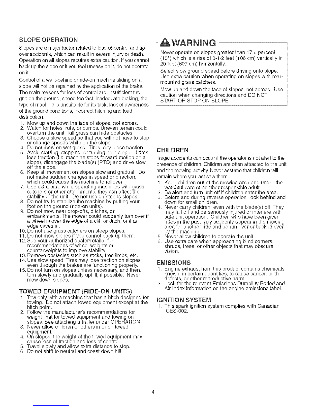
Never operate on slopes greater than 17.6 percent
(10 °) which is a rise of 3-1/2 feet (106 cm) vertically in
20 feet (607 cm) horizontally.
Select slow ground speed before driving onto slope.
Use extra caution when operating on slopes with rear-
mounted grass catchers.
Mow up and down the face of slopes, not across. Use
caution when changing directions and DO NOT
START OR STOP ON SLOPE.
Tragic accidents can occur if the operator is not alert to the
presence of children. Children are often attracted to the unit
and the mowing activity. Never assume that children will
remain where you last saw them.
1. Keep children out of the mowing area and under the
watchful care of another responsible adult.
2. Be alert and turn unit off if children enter the area.
3. Before and during reverse operation, look behind and
down for small children.
4. Never carry children, even with the blade(s) off. They
may fall offand be seriously injured or interfere with
safe unit operation. Children who have been given
by the machine.
5. Never allow children to operate the unit.
6. Use extra care when approaching blind corners,
shrubs, trees, or other objects that may obscure
vision,
EMISSIONS
1, Engine exhaust from this product contains chemicals
known, in certain quantities, to cause cancer, birth
defects, or other reproductive harm,
2, Look for the relevant Emissions Durability Period and
Air Index information on the engine emissions label,
mGNmTmONSYSTEM
1, This spark ignition system complies with Canadian
ICES-002,
Page 5
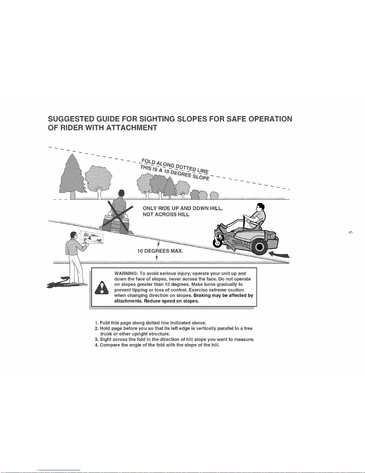
SUGGESTED GUIDE FOR SIGHTING SLOPES FOR SAFE OPERATION
OF RIDER WiTH ATTACHMENT
ONLY RmDE UP AND DOWN HILL,
NOT ACROSS HiLL
10 DEGREES MAX.
WARNING: To avoid serious injury, operate your unit up and
down the face of slopes, never across the face. Do not operate
on slopes greater than 10 degrees, Make turns gradually to
prevent tipping or Ioss of control. Exercise extreme caution
when changing direction on slopes, Braking may be affected by
attachments. Reduce speed on slopes.
_b
1. Fold this page aIong dotted Iine indicated above.
2, Hold page before you so that its left edge is vertically parallel to a tree
trunk or other upright structure.
3, Sight across the fold in the direction of hill slope you want to measure,
4, Compare the angle of the fold with the slope of the hill,
Page 6
SERVICE AND MAINTENANCE
Safe Handling of Gasoline
1, Extinguish all cigarettes, cigars, pipes, and other
sources of ignition,
2, Use only approved gasoline containers,
3, Never remove the gas cap or add fuel with the engine
running, Allow the engine to cool before refueling,
4, Never fuel the machine indoors,
5, Never store the machine or fuel container where there
is an open flame, spark, or pilot light such as near a
water heater or other appliance,
6, Never fill containers inside a vehbb or on a truck bed
with a plastic bed liner, Always place containers on
the ground away from your vehicle before filling,
7, Remove gas-powered equipment from the truck or
trailer and refuel it on the ground, If this is not
8, Keep nozzle in contact with the rim of the fuel tank or
tighten securely,
11, Use extra care in handling gasoline and other fuels,
13, If the fuel tank must be drained, it should be drained
outdoors,
14, Replace faulty sibncers/mufflers,
15, Maintain or replace safety and instruction labels as
necessary,
16, Use only Sears authorized replacement parts when
making repairs,
17, Always comply with factory specifications on all
settings and adjustments,
18, Only authorized Sears service locations should be
utilized for major service and repair requirements,
19, Never attempt to make major repairs on this unit
unless you have been properly trained, Improper
service procedures can result in hazardous operation,
equipment damage and voiding of manufacturer s
warranty,
20, On multiple blade mowers, take care as rotating one
blade can cause other blades to rotate,
securely,
Service & Maintenance
1, Never run the unit in an enclosed area where carbon
monoxide fumes may collect,
2, Keep nuts and bolts, especially blade attachment
bolts, tight and keep equipment in good condition,
3, Never tamper with safety devices, Check their proper
operation regularly and make necessary repairs if
they are not functioning properly,
4, Keep unit free of grass, leaves, or other debris build-
up, Clean up oil or fuel spillage, and remove any fuel-
soaked debris, Allow machine to cool before storage,
5, if you strike an object, stop and inspect the machine,
Repair, if necessary, before restarting,
6, Never make adjustments or repairs with the engine
running,
7, Check grass catcher components and the discharge
guard frequently and replace with manufacturers
recommended parts, when necessary,
8, Mower blades are sharp, Wrap the blade or wear
gloves, and use extra caution when servicing them,
9, Check brake operation frequently, Adjust and service
as required,
10, Maintain or replace safety and instructions labels, as
necessary,
11, Do not remove the fuel filter when the engine is hot
26, Models equipped with an engine radiator: WARNING:
remove the radiator cap while the
Stop the engine and wait until it is
use extreme care when removing the cap,
Page 7
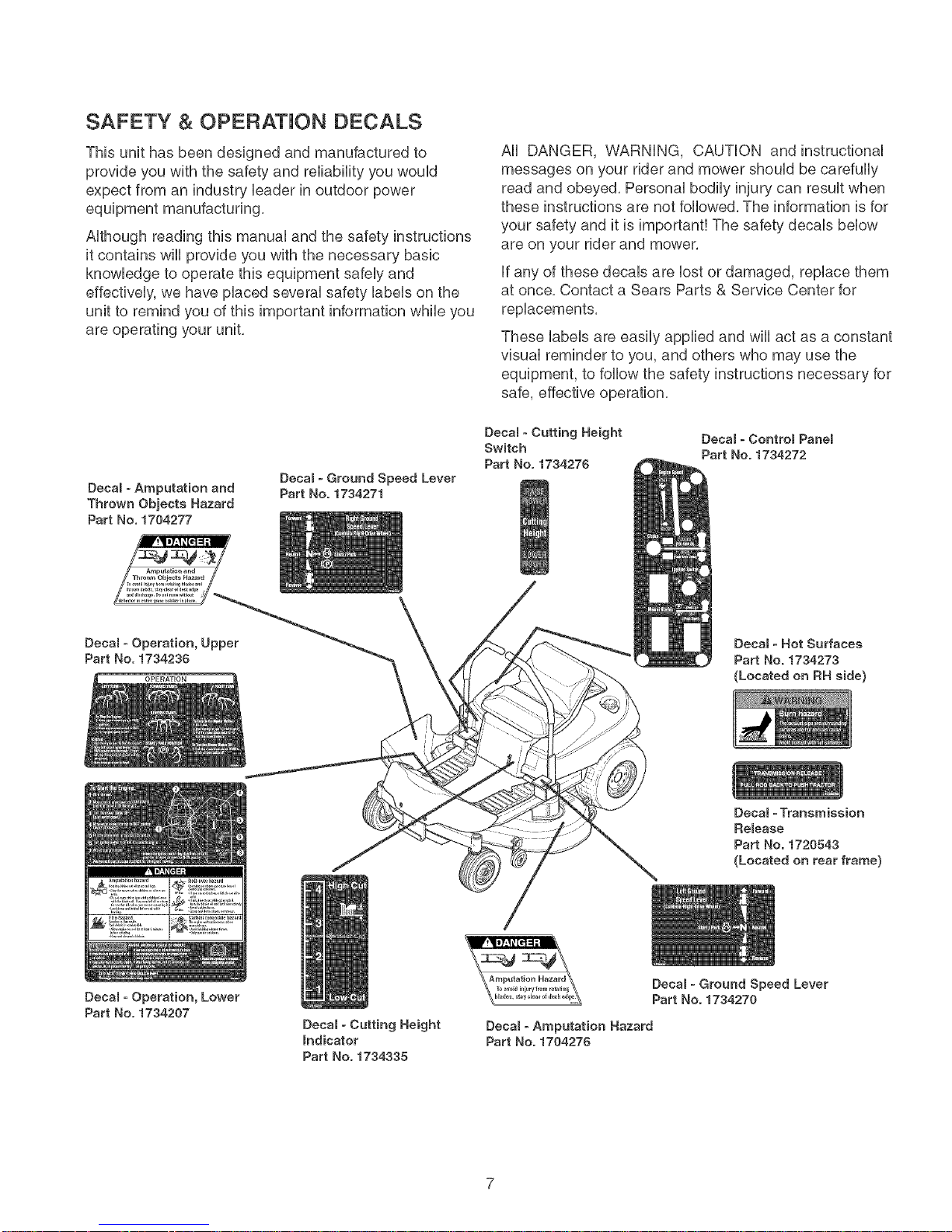
SAFETY & OPERATION DECALS
This unit has been designed and manufactured to
provide you with the safety and reliability you would
expect from an industry Headerin outdoor power
equipment manufacturing.
Aithough reading this manuai and the safety instructions
it contains will provide you with the necessary basic
knowiedge to operate this equipment safeiy and
effectiveiy, we have piaced severai safety iabeis on the
unit to remind you of this important information while you
are operating your unit.
Decam- Amputation and
Thrown Objects Hazard
Part No. 1704277
Decam - Ground Speed Lever
Part No. 1734271
All DANGER, VVARNING, CAUTION and instructional
messages on your rider and mower should be carefully
read and obeyed, Personal bodily injury can result when
these instructions are not followed, The information is for
your safety and it is important! The safety decals below
are on your rider and mower,
if any of these decals are lost or damaged, replace them
at once, Contact a Sears Parts & Service Center for
replacements,
These labels are easily applied and will act as a constant
visual reminder to you, and others who may use the
equipment, to follow the safety instructions necessary for
safe, effective operation,
Decam - Cutting Height
Switch
Part No. 1734275
Decal - Controm Panem
Part No. 1734272
Decam ° Operation, Upper
Part No. 1734236
Decam ° Operation, Lower
Part No. 1734207
Deeam - Cutting Height
Indicator
Part No. 1734335
Decal ° Hot Surfaces
Part He. 1734273
(Located on RH side)
Decal - Transmission
Remease
Part No. 1720543
(Located on rear frame}
Decam - Ground Speed Lever
Part No. 1734270
Decam - Amputation Hazard
Part No. 1704276
Page 8
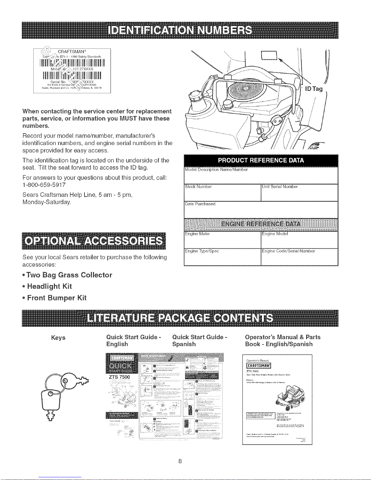
When contacting the service center for replacement
parts, service, or information you MUST have these
numbers.
Record your model name/number, manufacturer's
identification numbers, and engine serial numbers in the
space provided for easy access,
The identification tag is located on the underside of the
seat, Tilt the seat forward to access the ID tag,
For answers to your questions about this product, call:
1=800-659-5917
Sears Craftsman Help Line, 5 am =5 pm,
Monday-Saturday,
IDTag
Model Description Name/Number
Stock Number Jnit Serial Number
Date Purchased
See your local Sears retailer to purchase the following
accessories:
oTwo Bag Grass Collector
o Headlight Kit
* Front Bumper Kit
Keys
Quick Start Guide - Quick Start Guide -
English Spanish
Engine Make
Engine Type/Spec
Engine Model
Engine Code/Serial Number
Operator's Manual & Parts
Book - EngJishlSpanish
Operator's Manual
ZTS 75O0
zero_ll, R_arEn_4n_Ride_ ,qthEle_ricSta_
10_2,,00_1_ B,i_ __r_o,,_h _2¸¸r_}
@
...... t_
Page 9
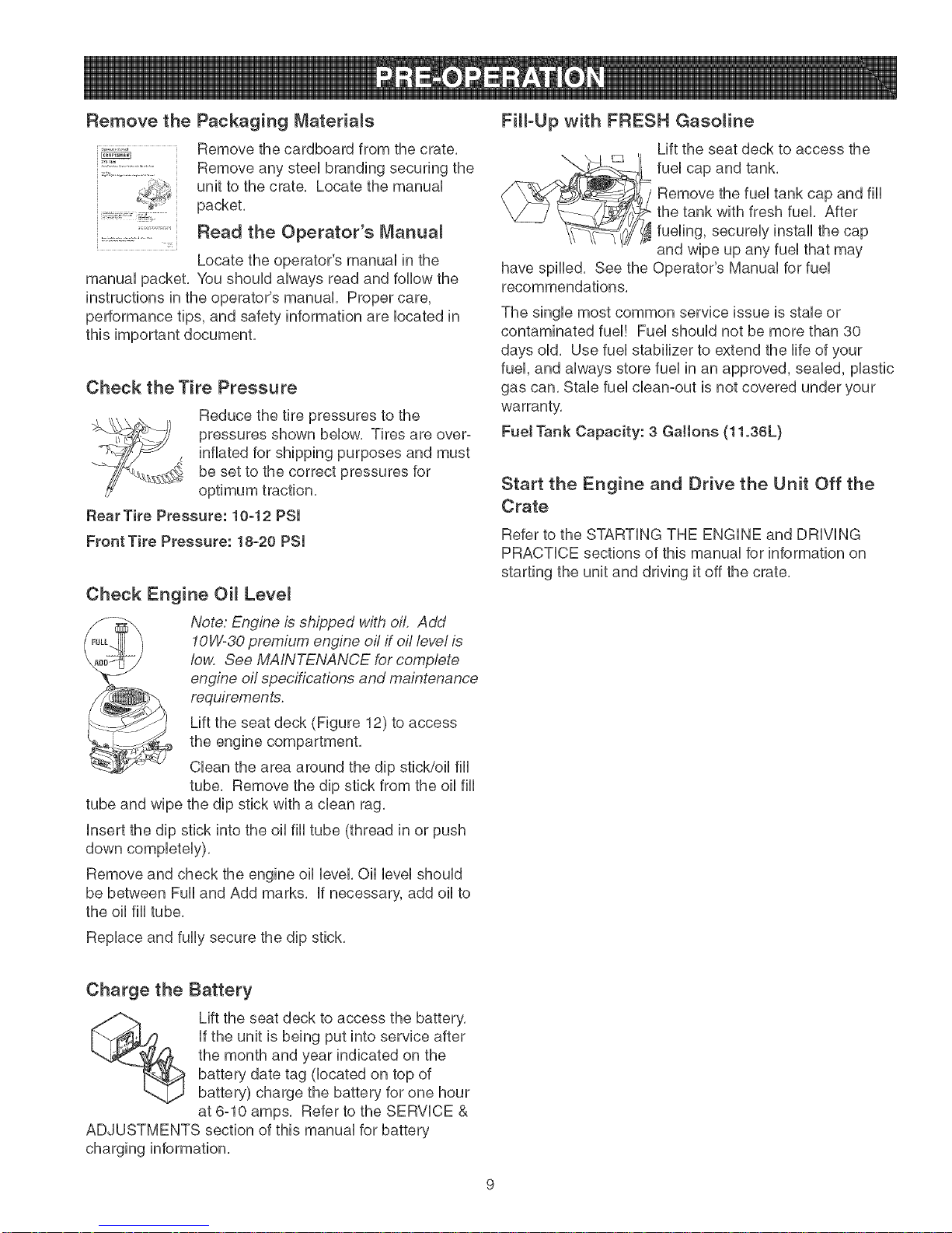
Remove the
i ::; :::x=;::: :......... ;;5
manual packet. You should always read and follow the
instructions in the operator's manual. Proper care,
performance tips, and safety information are located in
this important document.
Packaging Materials
Remove the cardboard from the crate,
Remove any steel branding securing the
unit to the crate, Locate the manual
packet.
Read the Operator's Manua_
Locate the operator's manual in the
Check the Tire Pressure
Reduce the tire pressures to the
pressures shown below. Tires are over-
inflated for shipping purposes and must
be set to the correct pressures for
optimum traction.
Rear Tire Pressure: 10-12 PSi
Front Tire Pressure: 18-20 PSI
Check Engine OH Leve_
Note: Engine is shipped with oil. Add
10W°30 premium engine oil if oil level is
low. See MAINTENANCE for complete
engine oil specifications and maintenance
requirements.
Lift the seat deck (Figure 12) to access
the engine compartment.
Clean the area around the dip stick/oil fill
tube. Remove the dip stick from the oil fill
tube and wipe the dip stick with a clean rag.
Insert the dip stick into the oil fill tube (thread in or push
down completely).
Remove and check the engine oil level. Oil level should
be between Full and Add marks. If necessary, add oil to
the oil fill tube.
Fill-Upwith FRESH Gasoline
Lift the seat deck to access the
//_L fuel cap and tank.
Remove the fuel tank cap and fill
the tank with fresh fuel. After
fueling, securely install the cap
and wipe up any fuel that may
have spilled. See the Operator's Manual for fuel
recommendations.
The single most common service issue is stale or
contaminated fuel! Fuel should not be more than 30
days old. Use fuel stabilizer to extend the life of your
fuel, and always store fuel in an approved, sealed, plastic
gas can, Stab fuel clean-out is not covered under your
warranty,
Fuet Tank Capacity: 3 Gallons (11.36L)
Start the Engine and Drive the Unit Off the
Crate
Refer to the STARTING THE ENGINE and DRIVING
PRACTICE sections of this manual for information on
starting the unit and driving it off the crate,
Replace and fully secure the dip stick.
Charge the Battery
Lift the seat deck to access the battery.
if the unit is being put into service after
the month and year indicated on the
battery date tag (located on top of
battery) charge the battery for one hour
at 6-10 amps. Refer to the SERVICE &
ADJUSTMENTS section of this manual for battery
charging information.
Page 10
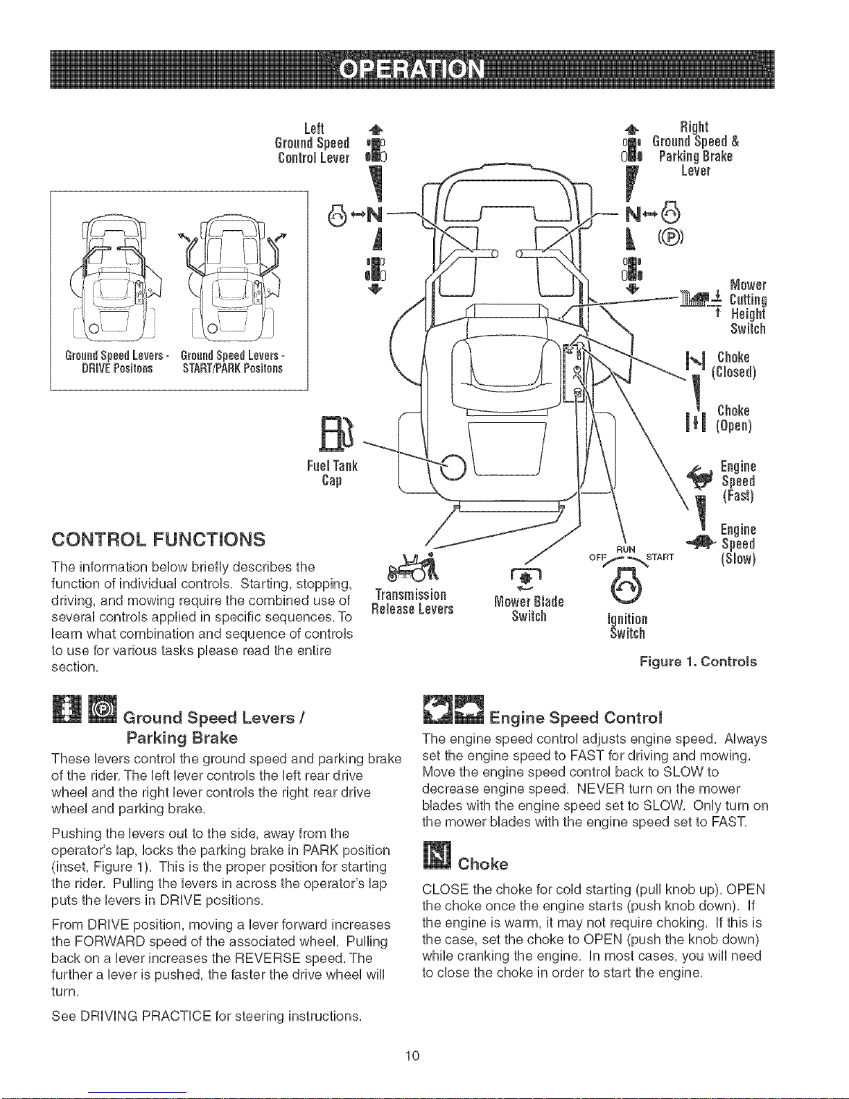
GroundSpeed
Control Lever
(;roundSpeedLevers= GroundSpeedLeve_s=
DRmVEPositens START/PARKPositens
Left
CONTROL FUNCTIONS
The information below briefly describes the
function of individual controls, Starting, stopping,
driving, and mowing require the combined use of
several controls applied in specific sequences, To
learn what combination and sequence of controls
to use for various tasks please read the entire
section,
Ground Speed Levers/
Parking Brake
These levers control the ground speed and parking brake
of the rider, The left lever controls the left rear drive
wheel and the right lever controls the right rear drive
wheel and parking brake,
Pushing the levers out to the side, away from the
operator's lap, locks the parking brake in PARK position
(inset, Figure 1), This is the proper position for starting
the rider, Pulling the levers in across the operator's lap
puts the levers in DRIVE positions,
From DRIVE position, moving a lever forward increases
the FORWARD speed of the associated wheel, Pulling
back on a lever increases the REVERSE speed, The
further a lever is pushed, the faster the drive wheel will
turn,
Figure 1. Controls
_ll_ Engine Speed Contro_
The engine speed control adjusts engine speed, Always
set the engine speed to FAST for driving and mowing,
Move the engine speed control back to SLOW to
decrease engine speed, NEVER turn on the mower
blades with the engine speed set to SLOW, Only turn on
the mower blades with the engine speed set to FAST,
Choke
CLOSE the choke for cold starting (pull knob up), OPEN
the choke once the engine starts (push knob down), If
the engine is warm, it may not require choking, If this is
the case, set the choke to OPEN (push the knob down)
while cranking the engine, In most cases, you will need
to close the choke in order to start the engine,
See DRIVING PRACTICE for steering instructions,
10
Page 11
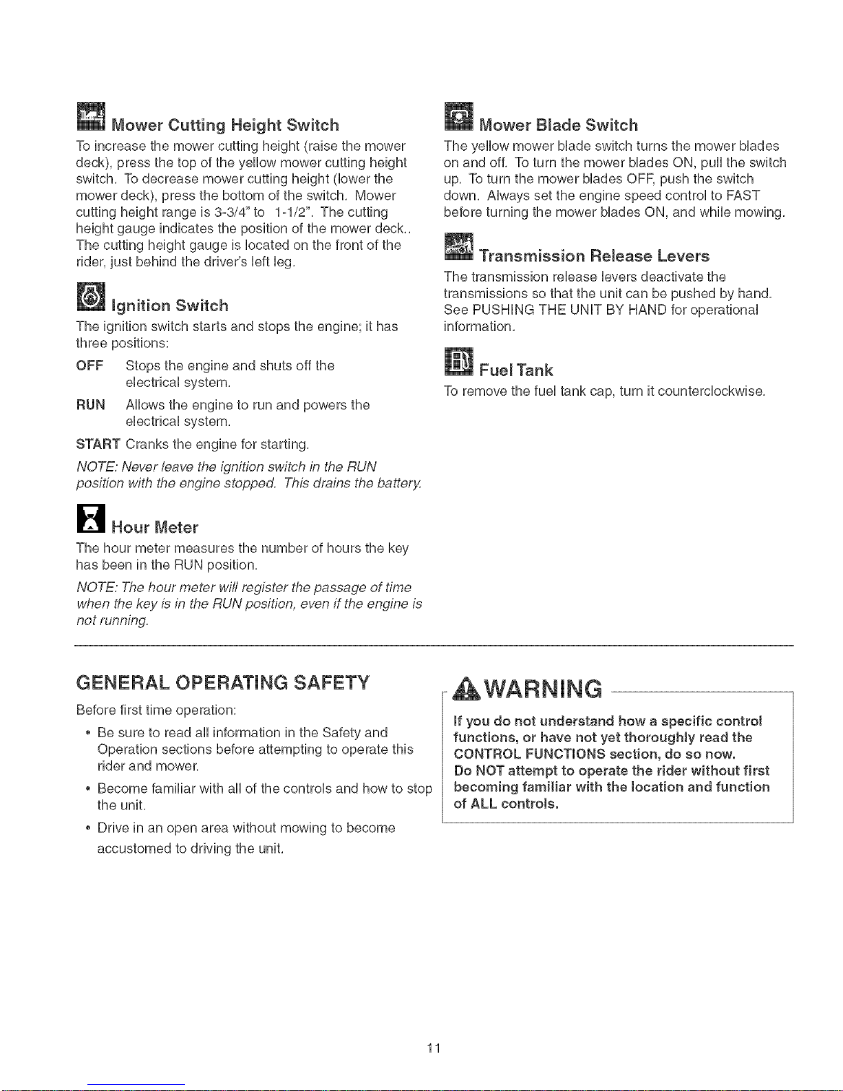
Mower Cutting Height Switch
To increase the mower cutting height {raise the mower
deck), press the top of the yellow mower cutting height
switch. To decrease mower cutting height (lower the
mower deck), press the bottom of the switch. Mower
cutting height range is 3o3/4" to t ol/2". The cutting
height gauge indicates the position of the mower deck..
The cutting height gauge is located on the front of the
rider, just behind the driver's [eft leg.
Ignition Switch
The ignition switch starts and stops the engine; it has
three positions:
OFF Stops the engine and shuts off the
electrical system.
RUN Allows the engine to run and powers the
electrical system,
START Cranks the engine for starting,
NOTE." Never leave the ignition switch in the RUN
position with the engine stopped. Thb drains the battery:
B Hour Meter
Mower Blade Switch
The yellow mower Made switch turns the mower blades
on and off. To turn the mower blades ON, pu[[ the switch
up. To turn the mower blades OFF, push the switch
down. Always set the engine speed control to FAST
before turning the mower blades ON, and while mowing.
Transmission ReJease Levers
The transmission release levers deactivate the
transmissions so that the unit can be pushed by hand.
See PUSHING THE UNIT BY HAND for operational
information,
Fuel Tank
To remove the fuel tank cap, turn it counterclockwise.
The hour meter measures the number of hours the key
has been in the RUN position.
NOTE: The hour meter wifl register the passage of time
when the key b in the RUN position, even if the engine is
not running.
GENERAL OPERATING SAFETY
Before first time operation:
,, Be sure to read all information in the Safety and
Operation sections before attempting to operate this
rider and mower,
o Become familiar with a[[ of the controls and how to stop
the unit.
Drive in an open area without mowing to become
accustomed to driving the unit.
if you do not understand how a specific control
functions, or have not yet thoroughly read the
CONTROL FUNCTIONS section, do so now.
Do NOT attempt to operate the rider without first
becoming familiar with the tocation and function
of ALL controls.
11
Page 12
CHECKS BEFORE STARTING
o Check that the crankcase oil is filled to full mark on
dipstick,
* Fill the fuel tank with fresh fuel,
FUEL RECOMMENDATIONS
For daily operation: Use only unleaded gasoline with a
pump sticker octane rating of 87 or higher, Gasohol (up
to 10% ethyl alcohol, 90% unleaded gasoline by volume)
is approved as a fuel, Methyl Teriary Butyl Ether (MTBE)
and unleaded gasoline blends (up to a maximum of 15%
MTBE by volume) are approved as a fuel, No other
gasoline/alcohol or gasoline/ether blends are approved,
Do not use fuel additives other than fuel stabilizer,
For storage: CAUTION: Alcohol blended fuels (called
gasohol or using ethanol or methanol) can attract
moisture which leads to separation and formation of
acids during storage, Acidic gas can damage the fuel
system of an engine while in storage,
To avoid engine problems always use fuel stabilizer,
especially before storage of 30 days or longer, Use fresh
fuel next season, See STORAGE instructions for
additional information,
Never use engine or carburetor cleaner products in the
fuel tank or permanent damage may occur, To add fuel:
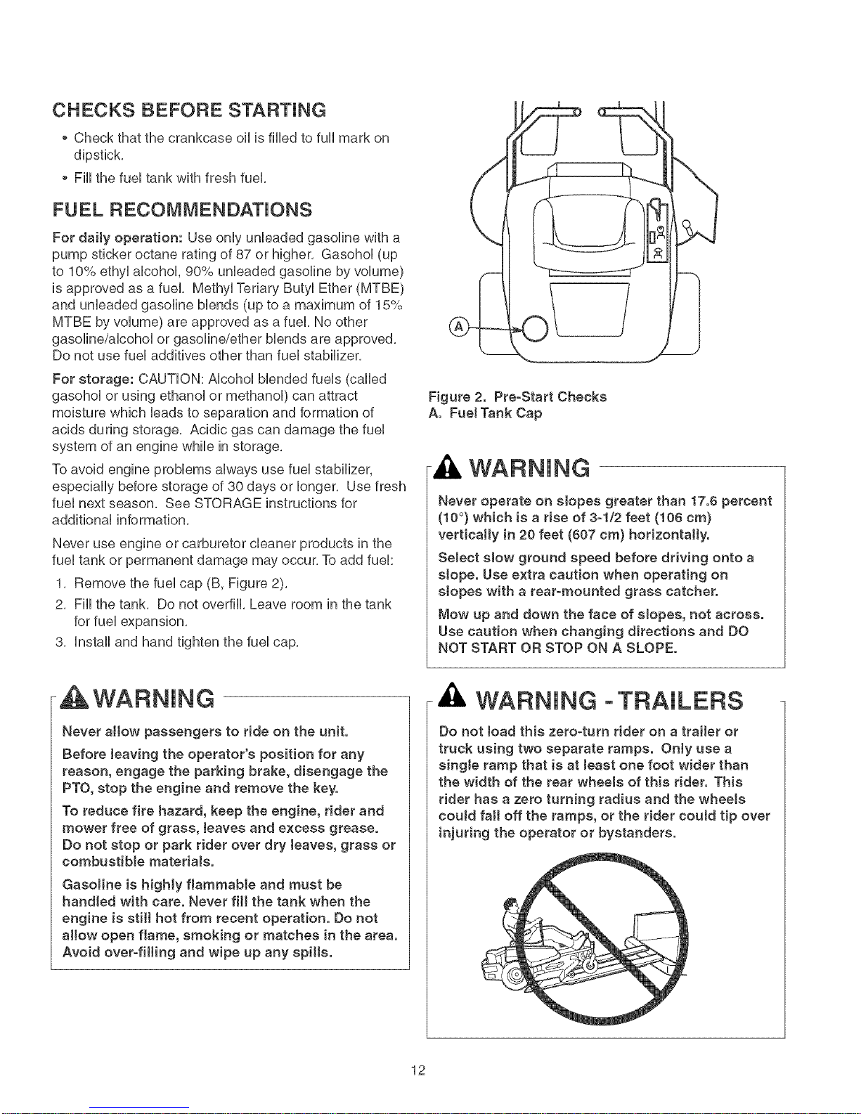
1, Remove the fuel cap (B, Figure 2),
2, Fill the tank, Do not overfill, Leave room in the tank
for fuel expansion,
3, Install and hand tighten the fuel cap,
Figure 2. Pre-Start Checks
A. FueJ Tank Cap
WARNING
Never operate on slopes greater than 17.6 percent
(10 °) which is a rise of 3-1/2 feet (106 cm)
vertically in 20 feet (607 cm) horizontally.
SeJect slow ground speed before driving onto a
slope. Use extra caution when operating on
slopes with a rear-mounted grass catcher.
Mow up and down the face of slopes, not across.
Use caution when changing directions and DO
NOT START OR STOP ON A SLOPE.
WARNING
Never allow passengers to ride on the unit.
Before leaving the operator's position for any
reason, engage the parking brake, disengage the
PTO, stop the engine and remove the key.
To reduce fire hazard, keep the engine, rider and
mower free of grass, teaves and excess grease.
Do not stop or park rider over dry teaves, grass or
combustible matedaJs.
GasoJine is higHy flammaMe and must be
bandied with care. Never fill the tank when the
engine is stilt hot from recent operation. Do not
allow open flame, smoking or matches in the area.
Avoid over-filling and wipe up any spitts.
WARNING oTRAILERS
Do not toad this zero=turn rider on a trailer or
truck using two separate ramps. OnJy use a
singJe ramp that is at teast one foot wider than
the width of the rear wheels of this rider. This
rider has a zero turning radius and the wheeJs
couJd fall off the ramps, or the rider coutd tip over
injuring the operator or bystanders.
12
Page 13
EMERGENCY STOPPING PUSHING THE F{JDER BY HAND
Hnthe event of an emergency the engine can be stopped
by simpHyturning the ignition switch to STOR Use this
method onHyin emergency situations. For normaH engine
shut down foHHowthe procedure given in STOPPHNG THE
RHDER AND ENGHNE.
STOPPING THE F{JDER & ENGINE
1. Return the ground speed controHHeversto
START/PARK positions to stop rider movement and
engage the parking brake.
2. Turn off the mower bHadesby pushing the mower
Made switch down to the OFF position.
3. Move the engine speed controHto SLOW position and
turn the ignition switch to OFR Remove the key.
STARTING THE ENGINE
1. While sitting in the seat, make sure the mower Made
switch is OFF and the ground speed controH Hevers
are Hockedin START/PARK positions.
2. Move the engine speed controHfuHHyforward to FAST.
Set the choke controHto CLOSED (puHHknob UP).
NOTE."A warm engine may not require choking. /n t,_is
case, set the choke control to OPEN (push knob down).
3. Hnsertthe key into the ignition switch and turn it to
START to crank the engine.
4. After the engine starts, reHeasethe key. HtwiHHreturn
to the RUN position. GraduaHHypush the choke knob
down to OPEN position. Warm the engine by running
it for at Heasta minute before turning on the mower
bHades,or driving the unit.
ALWAYS operate the unit with the engine speed
controJ set to FAST when mowing or driving.
NEVER engage the mower blades with the engine
speed set to SLOW.
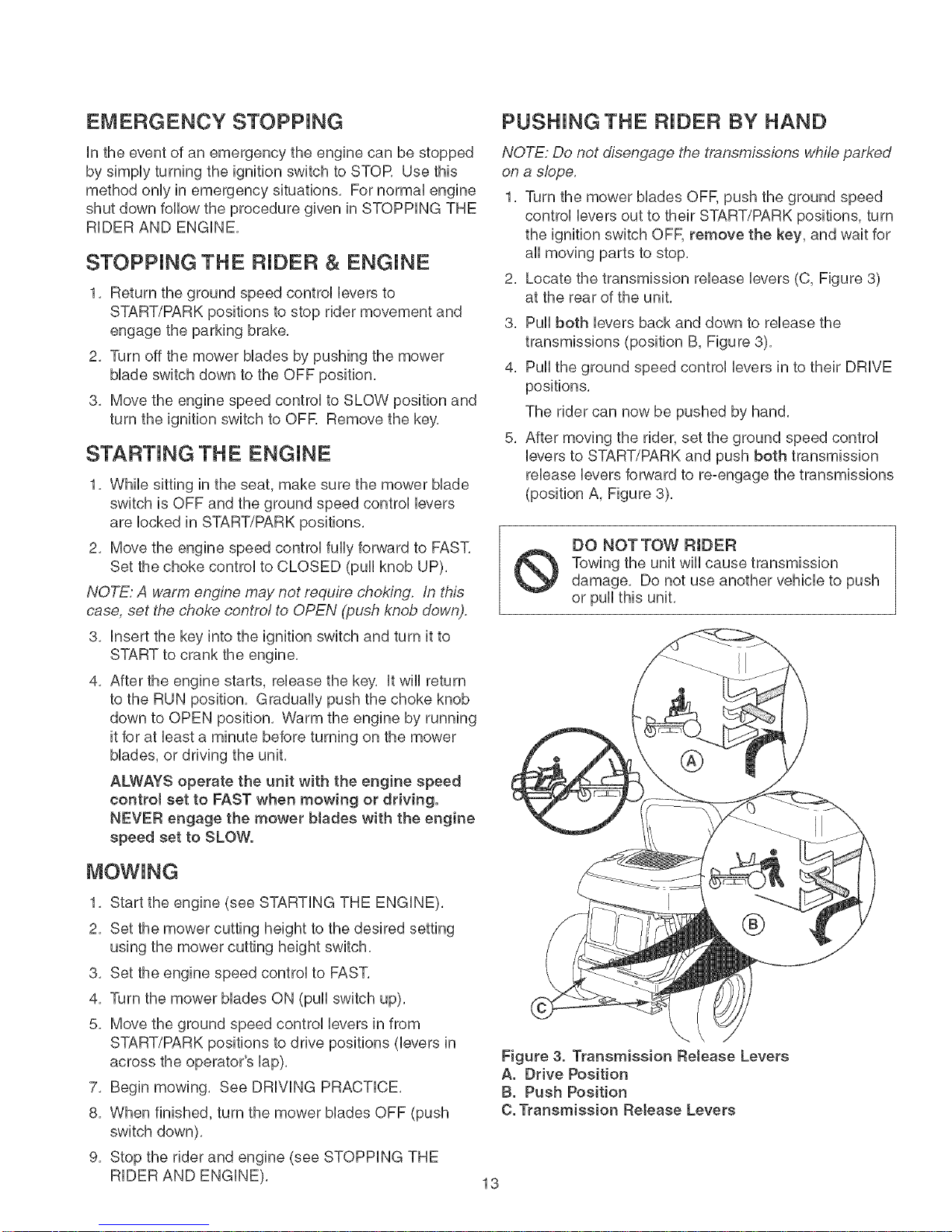
NOTE: Do not disengage the transmissions while parked
on a slope.
1. Turn the mower bHadesOFE push the ground speed
controHHeversout to their START/PARK positions, turn
the ignition switch OFF, remove the key, and wait for
aHHmoving parts to stop.
2. Locate the transmission reHeaseHevers(C, Figure 3)
at the rear of the unit.
3. PuHHboth Heversback and down to reHease the
transmissions (position B, Figure 3).
4. PuHHthe ground speed controHHeversin to their DRHVE
positions.
The rider can now be pushed by hand.
5. After moving the rider, set the ground speed controH
Heversto START/PARK and push both transmission
reHeaseHeversforward to re-engage the transmissions
(position A, Figure 3).
DO NOTTOW RIDER
Towing the unit wiHHcause transmission
damage. Do not use another vehicHeto push
or puHHthis unit.
MOWING
1. Start the engine (see STARTHNGTHE ENGHNE).
2. Set the mower cutting height to the desired setting
using the mower cutting height switch.
3. Set the engine speed controHto FAST.
4. Turn the mower bHadesON (puHHswitch up).
5. Move the ground speed controH Heversin from
START/PARK positions to drive positions (Heversin
across the operator's Hap).
7. Begin mowing. See DRHVHNGPRACTHCE.
8. When finished, turn the mower bHadesOFF (push
switch down).
9. Stop the rider and engine (see STOPPHNG THE
RHDERAND ENGHNE).
Figure 3. Transmission Reteaee Levers
A. Drive Position
B. Push Position
C. Transmission Reteaee Levers
13
Page 14
DRiViNG PRACTICE-
BASIC DRIWNG
WARNING: Never operate on sUopesgreater than 17.6%
(10°). See SLOPE OPERATION in the safety section.
Zero turn riders operate differentUy from other four°
wheeUed vehicUes. The drive wheeUsare aUsoyour
steering wheeUs, ff you cannot drive the unit on a hill you
wHUnot be aMe to steer the unit on it. Operating zero
turn units on sUopesrequires extra caution.
The Uevercontrols of the zero turn rider are very
responsive, and Uearning to gain a smooth and efficient
controUof the rider's forward, reverse, and turning
movements wHUtake some practice.
Spend some time going through the foflowing maneuvers
and becoming familiar with how the unit accelerates,
travels, and steers -- before you begin mowing --is
absolutely essential to getting the most out of the zero
turn rider.
Locate a smooth, fiat area of your tawn -- one with
plenty of room to maneuver. (Clear the area of objects,
people and animals before you begin.) Operate the unit
at mid-throttle during this practice session (ALVVAYS
operate at full throttle when mowing), and turn slowly to
prevent tire slippage and damage to your lawn.
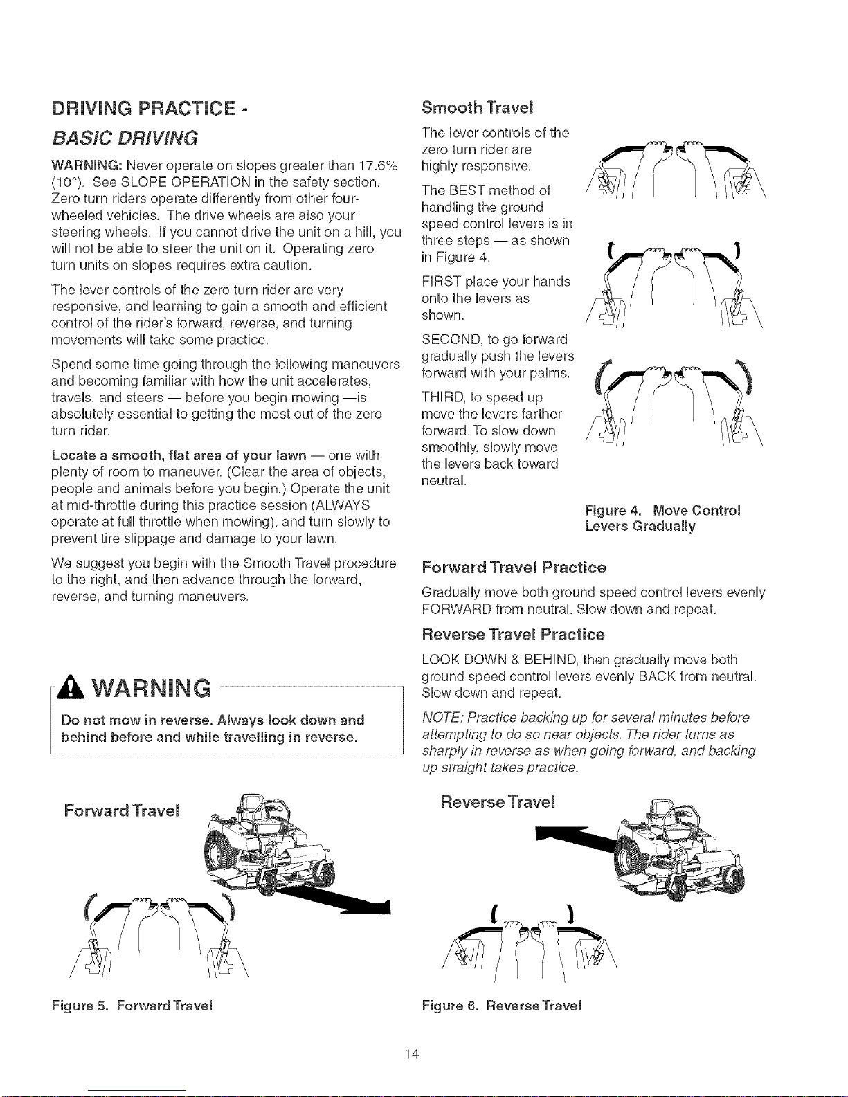
Smooth Trave_
The lever controls of the
zero turn rider are
highly responsive,
The BEST method of
speed control levers is in
three steps -- as shown
in Figure 4.
FIRST place your hands
onto the levers as
shown.
SECOND, to go forward
gradually push the levers
forward with your palms.
THIRD, to speed up
move the levers farther
forward. To slow down
smoothly, slowly move
the levers back toward
neutral.
Figure 4. Move Controt
Levers Gradually
We suggest you begin with the Smooth Travel procedure
to the right, and then advance through the forward,
reverse, and turning maneuvers.
WARNING
Do not mow in reverse. Always took down and
behind before and while travelling in reverse.
Forward Trave_
Forward Trave_ Practice
Gradually move both ground speed control levers evenly
FORWARD from neutral. Slow down and repeat.
Reverse Trave_ Practice
LOOK DOWN & BEHIND, then gradually move both
ground speed control levers evenly BACK from neutral.
Slow down and repeat.
NOTE: Practice backing up for several minutes before
attempting to do so near objects. The rider turns as
sharply in reverse as when going forward, and backing
up straight takes practice.
Reve rse Trave J
Figure 5. Forward Travet Figure 6. Reverse Travel
14
Page 15
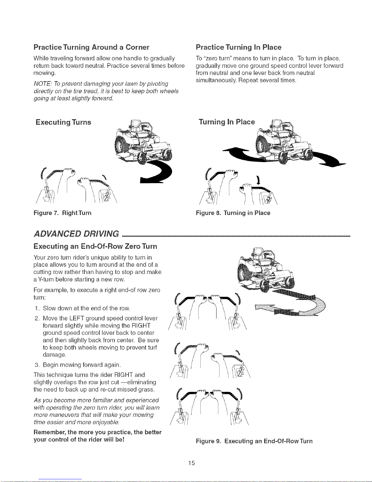
Practice Turning Around a Corner
Whib traveling forward allow one handb to gradually
return back toward neutral, Practice several times before
mowing,
NOTE: Toprevent damaging your lawn by pivoting
directly on the tire tread, it ie best to keep both wheele
going at least sfight/y forward.
Practice Turning mnP_ace
To "zero turn" means to turn in place, To turn in place,
gradually move one ground speed control lever forward
from neutral and one lever back from neutral
simultaneously, Repeat several times,
Executing Turns
Figure 7. RightTum Figure 8. Turning in Place
ADVANCED DRiViNG
Executing an End-Of-Row Zero Turn
Your zero turn rider's unique ability to turn in
place allows you to turn around at the end of a
cutting row rather than having to stop and make
a Yoturn before starting a new row,
For example, to execute a right end-of row zero
turn:
1, Slow down at the end of the row,
2, Move the LEFT ground speed control lever
forward slightly while moving the RIGHT
ground speed control lever back to center
and then slightly back from center, Be sure
to keep both wheels moving to prevent turf
damage,
3, Begin mowing forward again,
This technique turns the rider RIGHT and
slightly overlaps the row just cut --eliminating
the need to back up and re-cut missed grass,
As you become more familiar and experienced
with operating the zero turn rider, you wifl learn
more maneuvers that will make your mowing
time easier and more enjoyable.
Remember, the more you practice, the better
your control of the rider wilt be!
Figure 9. Executing an End-Of-RowTum
15
Page 16
MOWER DECK REMOVAL &
NOTE: Perform mower removal and installation on a
hard, level surface such as a concrete floor.
WARNING
After towering the mower cutting height, engage
parking brake, turn off the mower blades, turn the
ignition switch to STOP, and remove key before
attempting to install or remove the mower.
Removing the Mower Deck
1, Turn the mower Mades OFF, put the ground speed
control Ueversin START/PARK position, turn the
ignition OFF, and wait for aHmoving parts to stop,
2, Pivot the front wheeUsforward,
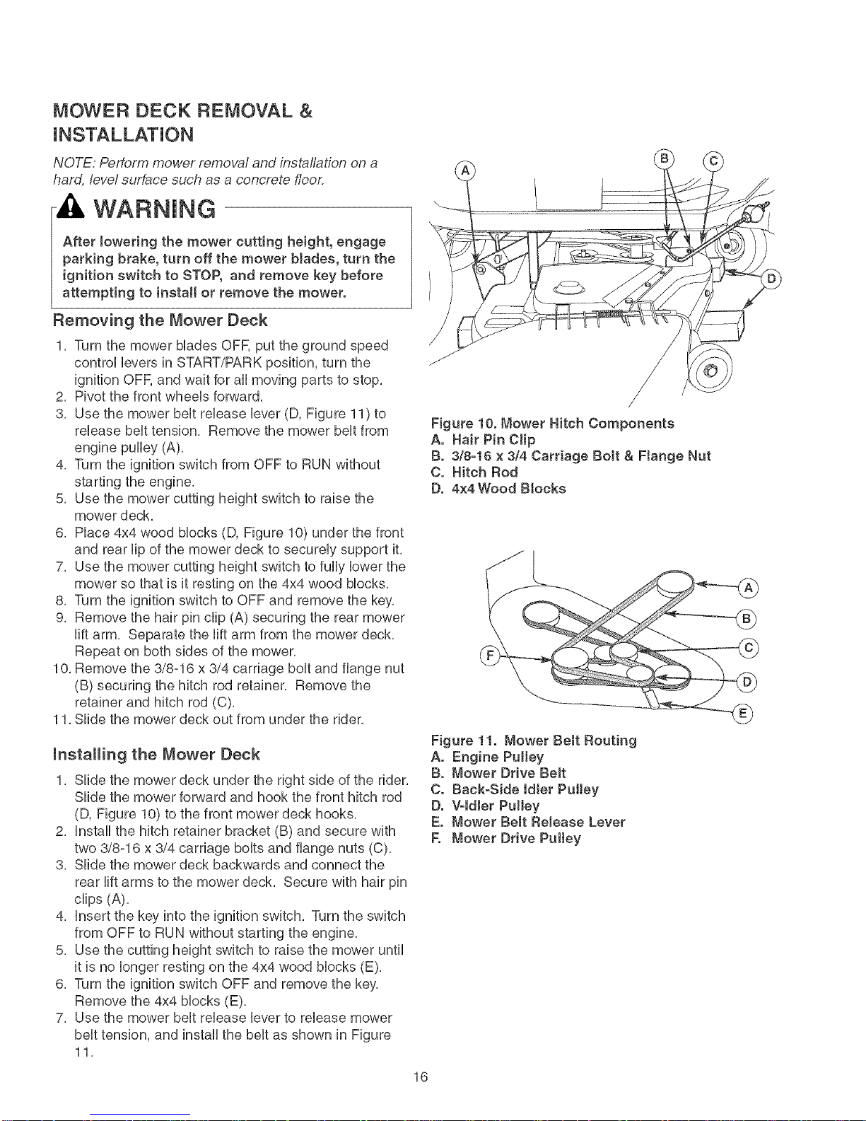
3, Use the mower beUtreUease Uever(D, Figure 11) to
reUeasebeUttension, Remove the mower beUtfrom
engine pulley (A),
4, Turn the ignition switch from OFF to RUN without
starting the engine,
5, Use the mower cutting height switch to raise the
mower deck,
6, PUace4x4 wood Mocks (D, Figure 10) under the front
and rear lip of the mower deck to securely support it,
7, Use the mower cutting height switch to fully lower the
mower so that is it resting on the 4x4 wood blocks,
8, Turn the ignition switch to OFF and remove the key,
9, Remove the hair pin clip (A) securing the rear mower
lift arm, Separate the lift arm from the mower deck,
Repeat on both sides of the mower,
1O,Remove the 3/8-16 x 3/4 carriage bolt and flange nut
(B) securing the hitch rod retainer, Remove the
retainer and hitch rod (C).
11, Slide the mower deck out from under the rider,
mnstaHing the Mower Deck
1, Slide the mower deck under the right side of the rider,
Slide the mower forward and hook the front hitch rod
(D, Figure 10) to the front mower deck hooks,
2, Install the hitch retainer bracket (B) and secure with
two 3/8-16 x 3/4 carriage bolts and flange nuts (C),
3, Slide the mower deck backwards and connect the
rear lift arms to the mower deck, Secure with hair pin
clips (A),
4, Insert the key into the ignition switch, Turn the switch
from OFF to RUN without starting the engine,
5, Use the cutting height switch to raise the mower until
it is no longer resting on the 4x4 wood blocks (E),
6, Turn the ignition switch OFF and remove the key,
Remove the 4x4 blocks (E),
7, Use the mower belt release lever to release mower
belt tension, and install the belt as shown in Figure
11,
Figure 10. Mower Hitch Components
A. Hair Pin Clip
B. 3/8-18 × 3/4 Carriage Bolt & Ftange Nut
C. Hitch Rod
D. 4×4 Wood Btocks
Figure 11. Mower Bett Routing
A. Engine Pultey
B. Mower Drive Belt
C. Back-Side Idler Pulley
D. V-ldier Pulley
E. Mower Bett Reiease Lever
E Mower Drive Puttey
16
Page 17

MAINTENANCE SCHEDULE
The following schedubs shouUdbe followed for normaUcare of your rider and mower,
RIDER MAINTENANCE, AH Mode_s Before Spring 8 25 100 200 Yearly
Each Use & Fall Hours Hours Hours Hours
Cban Debris from Rider and Engine Compartment * +
Cban Debris from Engine Cooling Areas & Air FHter * +
Check Tire Pressure +
Lubricate Rider & Mower * +
Cban Deck & Check/RepUace Mower BUades +
Cban Battery & CaMes +
Check Rider Safety System ** + + +
Check / Adjust PTO CUutch +
ENGmNE MAmNTENANCE, 8 Hours 25 Hours or 100 Hours 200 Hours 200 500
20HP Koh_er or Daily 2 Months or Annually or 2Years Hours Hours
Check Engine OHLevel * +
Replace Air Filter * +
Change Oil & Filter * +
Remove Shroud, Clean Cooling Fins * +
"Replace Fuel Filter t +
Check & Re=Gap / Replace Spark Plug + +
Service Starter Drive, Check & Adjust Valve +
Clearance t
ENGINE MAINTENANCE, 8 Hours 25 Hours 50 Hours 100 Hours 100-400
24HP Briggs & Stratton or Daily or Every or Every or Every Hours
Check Engine Oil Level * ®
Replace Air Filter * +
Change Oil * +
Change Oil & Filter * +
Clean Cooling Fins * +
Replace Spark Plugs ®
Replace Fuel Filter 1+ +
Clean Combustion Chamber ®
* More often in hot (over 85° F:30 ° C) weather or dusty operating conditions.
** Check the function of the safety system after the unit has been stored for 30 days or longer,
1+These services should be performed by Sears or other qualified service dealer,
Season Season Season
17
Page 18
Rider Maintenance items
WARNING
Move the ground speed Jevers to START/PARK
positions, turn the mower bJades OFF, turn the
ignition switch OFF, and wait for all moving parts
to stop before accessing the engine compartment
or performing any maintenance procedures.
ACCESSING THE ENGINE
COMPARTMENT
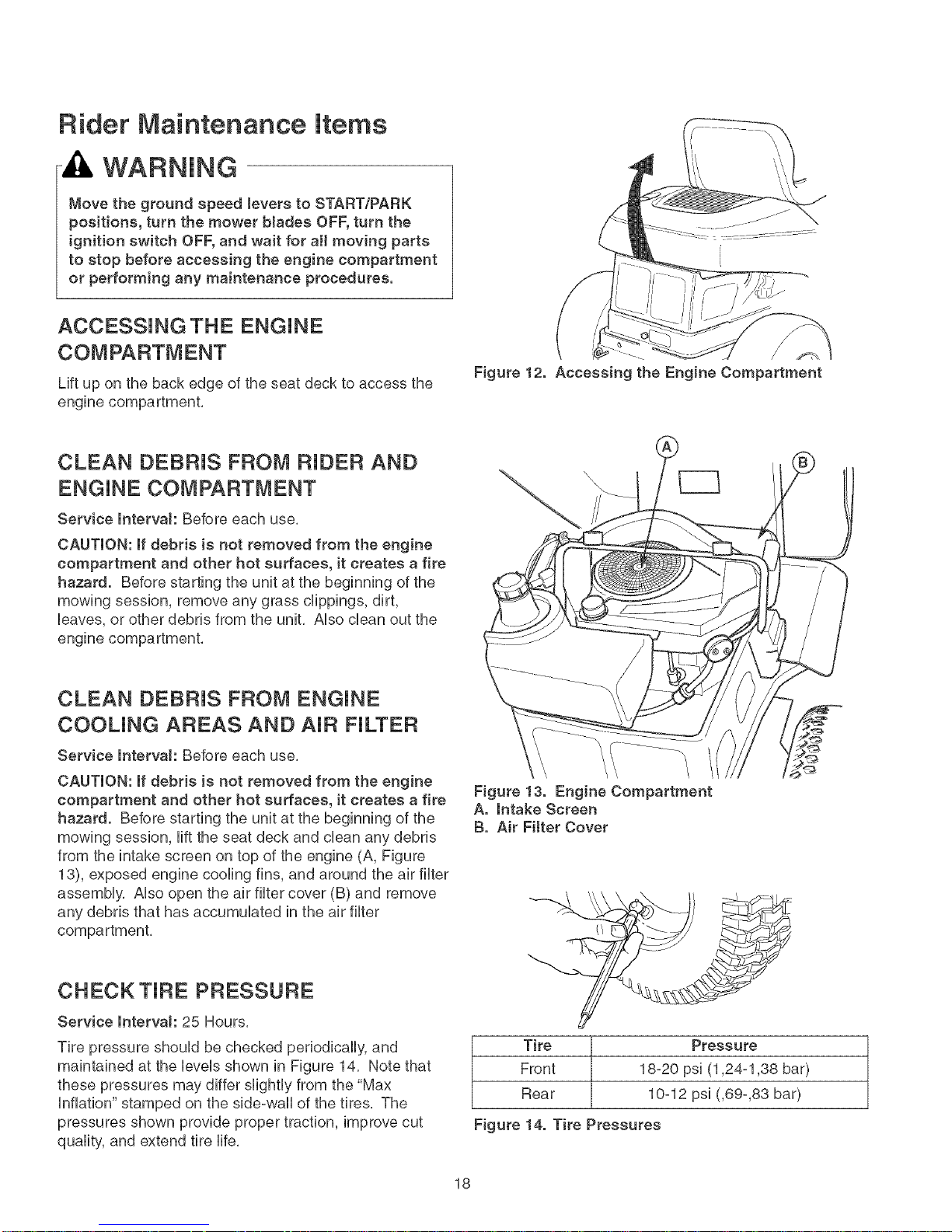
Lift up on the back edge of the seat deck to access the
engine compartment,
CLEAN DEBRIS FROM RIDER AND
ENGINE COMPARTMENT
Service lntervak Before each use,
CAUTION: if debris is not removed from the engine
compartment and other hot surfaces, it creates a fire
hazard. Before starting the unit at the beginning of the
mowing session, remove any grass clippings, dirt,
leaves, or other debris from the unit, Also clean out the
engine compartment,
Figure 12. Accessing the Engine Compartment
CLEAN DEBRIS FROM ENGINE
COOLING AREAS AND AIR FILTER
Service lnterva!: Before each use,
CAUTION: if debris is not removed from the engine
compartment and other hot surfaces, it creates a fire
hazard. Before starting the unit at the beginning of the
mowing session, lift the seat deck and clean any debris
from the intake screen on top of the engine (A, Figure
13), exposed engine cooling fins, and around the air filter
assembly, Also open the air filter cover (B) and remove
any debris that has accumulated in the air filter
CHECKTJRE PRESSURE
Service lntervaJ: 25 Hours,
Tire pressure should be checked periodically, and
maintained at the levels shown in Figure 14, Note that
these pressures may differ slightly from the "Max
Inflation" stamped on the side=waUof the tires, The
pressures shown provide proper traction, improve cut
quality, and extend tire life,
Figure !3. Engine Compartment
A. Intake Screen
B. Air Fitter Cover
T(re
Front
Rear
Figure 14. Tire Pressures
18-20 ps( (1,24-1,38 bar)
10-12 psi (,69-,83 bar)
Pressure
18
Page 19
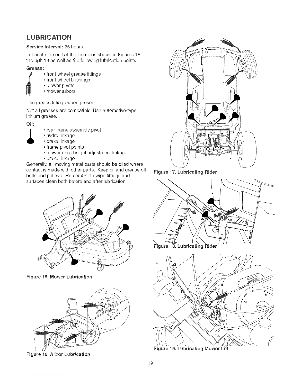
ServicelntervaJ: 25 hours,
Lubricate the unit at the Uocations shown in Figures 15
through 19 as well as the following Uubrication points,
Grease:
ofront wheeUgrease fittings
ofront wheeUbushings
* mower pivots
* mower arbors
Use grease fittings when present,
Not aHgreases are compatibUe, Use automotive4ype
Oil:
_ll o rear frame assembUy pivot
Generally, aHmoving metaUparts shouUdbe oiled where
contact is made with other parts, Keep oHand grease off
beUtsand pulleys, Remember to wipe fittings and
surfaces dean both before and after Uubrication,
* hydro Hnkage
* brake Hnkage
* frame pivot points
omower deck height adjustment Hnkage
obrake linkage
Figure 17. Lubricating Rider
\
\
Figure 18. Lubricating Rider
Figure 15. Mower Lubrication
Figure 16, Arbor Lubrication
Figure 19. Lubricating Mower Lift
19
Page 20
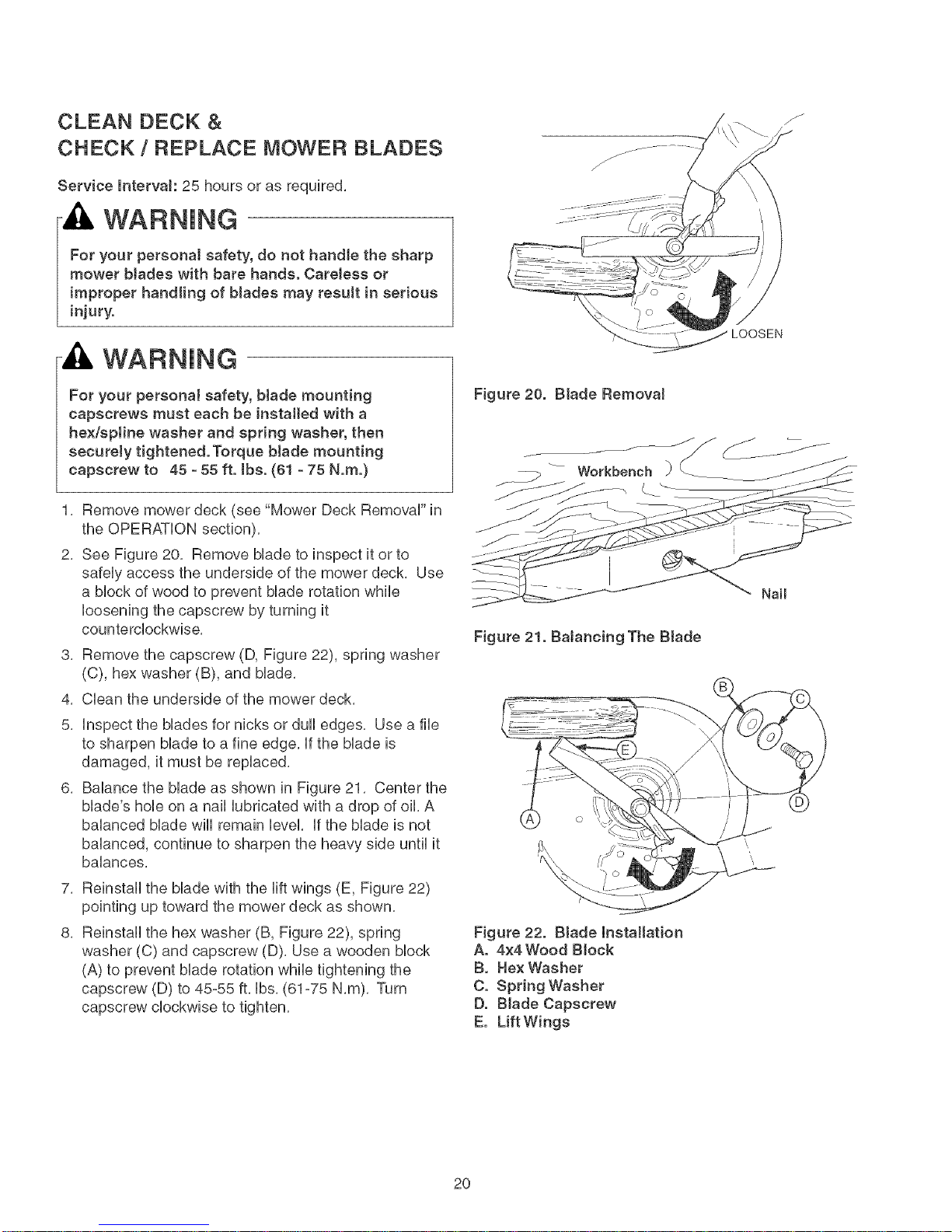
CLEAN DECK &
CHECK / REPLACE MOWER BLADES
Service lntervah 25 hours or as required,
WARNING
For your personal safety, do not handle the sharp
mower blades with bare hands. Careless or
improper handling of blades may result in serious
injury.
WARNING
LOOSEN
For your personal safety, btade mounting
capscrews must each be installed with a
hex/sptine washer and spring washer, then
securely tightened. Torque blade mounting
capscrew to 45 - 55 ft. tbs. (61 - 75 N.m.)
1, Remove mower deck (see "Mower Deck RemovaF in
the OPERATION section),
2, See Figure 20, Remove Made to inspect it or to
safeUyaccess the underside of the mower deck, Use
a bbck of wood to prevent Made rotation while
bosening the capscrew by turning it
counterdockwbe,
3, Remove the capscrew (D, Figure 22), spring washer
(C), hex washer (B), and Made,
4, Cban the underside of the mower deck,
5, Inspect the blades for nicks or dull edges, Use a file
to sharpen blade to a fine edge, If the blade is
damaged, it must be replaced,
6, Balance the blade as shown in Figure 21, Center the
blade's hole on a nail lubricated with a drop of oil, A
balanced blade will remain level, If the blade is not
balanced, continue to sharpen the heavy side until it
balances,
Figure 20. Blade RemovaJ
Nail
Figure 21. BaJancing The Btade
7, Reinstall the blade with the lift wings (E, Figure 22)
pointing up toward the mower deck as shown,
8, Reinstall the hex washer (B, Figure 22), spring
washer (C) and capscrew (D), Use a wooden block
(A) to prevent blade rotation while tightening the
capscrew (D) to 45-55 ft, Ibs, (61-75 N,m), Turn
capscrew clockwise to tighten,
Figure 22. Blade Installation
A. 4x4Wood Block
B. Hex Washer
C. Spring Washer
D. Blade Capscrew
E. Lift Wings
2O
Page 21
CLEANING THE BATTERY AND
Service lntervak 100 Hours
WARNING
Corrosion hazard.
Batteries contain acid. Always keep the
battery upright and do not spill the
eJectrolyte. Avoid contact with skin and
eyes.
Explosion hazard.
When removing or installing battery caMes,
disconnect the negative cable FmRSTand
reconnect it LAST. ff not done in this order,
the positive terminaJ can be shorted to the
frame by a tool.
Wear Protective Equipment
AJways wear gJoves and safety gJasses
when handling the battery and battery
cabJes.
CHECK RIDER SAFETY
SYSTEM
Service lntervak Every 100 hours, every spring/fall,
and after storage of 30 days or longer,
This unit is equipped with safety interlock switches,
These safety systems are present for your safety, Do
not attempt to bypass safety switches, and never
tamper with safety devices, Check their operation
regularly,
Operationa_ SAFETY Checks
TEST 1 -- ENGINESHOULD NOT CRANK iF:
* Mower blades switch is ON, OR
o Ground speed control levers are not in their
START/PARK positions,
TEST 2 -- ENGINESHOULD CRANK IF:
o Mower blade switch is OFF, AND
* Ground speed control levers are in their
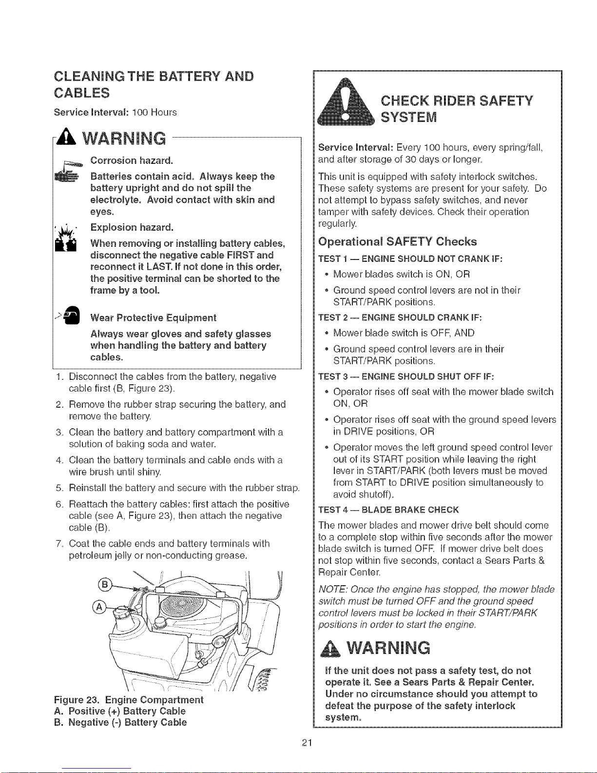
1, Disconnect the caMes from the battery, negative
cabb first (B, Figure 23),
2, Remove the rubber strap securing the battery, and
remove the battery,
3, Clean the battery and battery compartment with a
solution of baking soda and water,
4, Clean the battery terminals and cable ends with a
wire brush until shiny,
5, Reinstall the battery and secure with the rubber strap,
6, Reattach the battery cables: first attach the positive
cable (see A, Figure 23), then attach the negative
cable (B),
7, Coat the cable ends and battery terminals with
petroleum jelly or non-conducting grease,
TEST 3 -- ENGINESHOULD SHUT OFF IF:
° Operator rises off seat with the mower blade switch
ON, OR
* Operator rises off seat with the ground speed levers
in DRIVE positions, OR
o Operator moves the left ground speed control lever
out of its START position while leaving the right
lever in START/PARK (both levers must be moved
from START to DRIVE position simultaneously to
avoid shutoff),
TEST 4 -- BLADE BRAKE CHECK
The mower blades and mower drive belt should come
to a complete stop within five seconds after the mower
blade switch is turned OFF, If mower drive belt does
not stop within five seconds, contact a Sears Parts &
Repair Center,
NOTE: Once the engine has stopped, the mower blade
switch must be turned OFF and the ground speed
control levers must be locked in their START/PARK
positions in order to start the engine.
Figure 23. Engine Compartment
A. Positive (+) Battery CaMe
B. Negative (-) Battery Cabte
if the unit does not pass a safety test, do not
operate it. See a Sears Parts & Repair Center.
Under no circumstance should you attempt to
defeat the purpose of the safety interlock
system.
21
Page 22
CHECK / ADJUST PTO CLUTCH
WARNING
To avoid serious injury, perform adjustments only
with engine stopped, key removed and tractor on
tevet ground.
Service lntervaJ: 200 Hours.
The Power Take Off (PTO) dutch drives the mower
bUades. The PTO dutch is engaged and disengaged by
the mower Made switch. Check the PTO dutch
adjustment every 200 hours of operation. AUsoperform
the following procedure if the dutch is slipping, wHUnot
engage, or if a new dutch has been installed.
1. Remove key from ignition switch and disconnect
spark pUugwires to prevent the possibility of
accidental starting while the PTO is being adjusted.
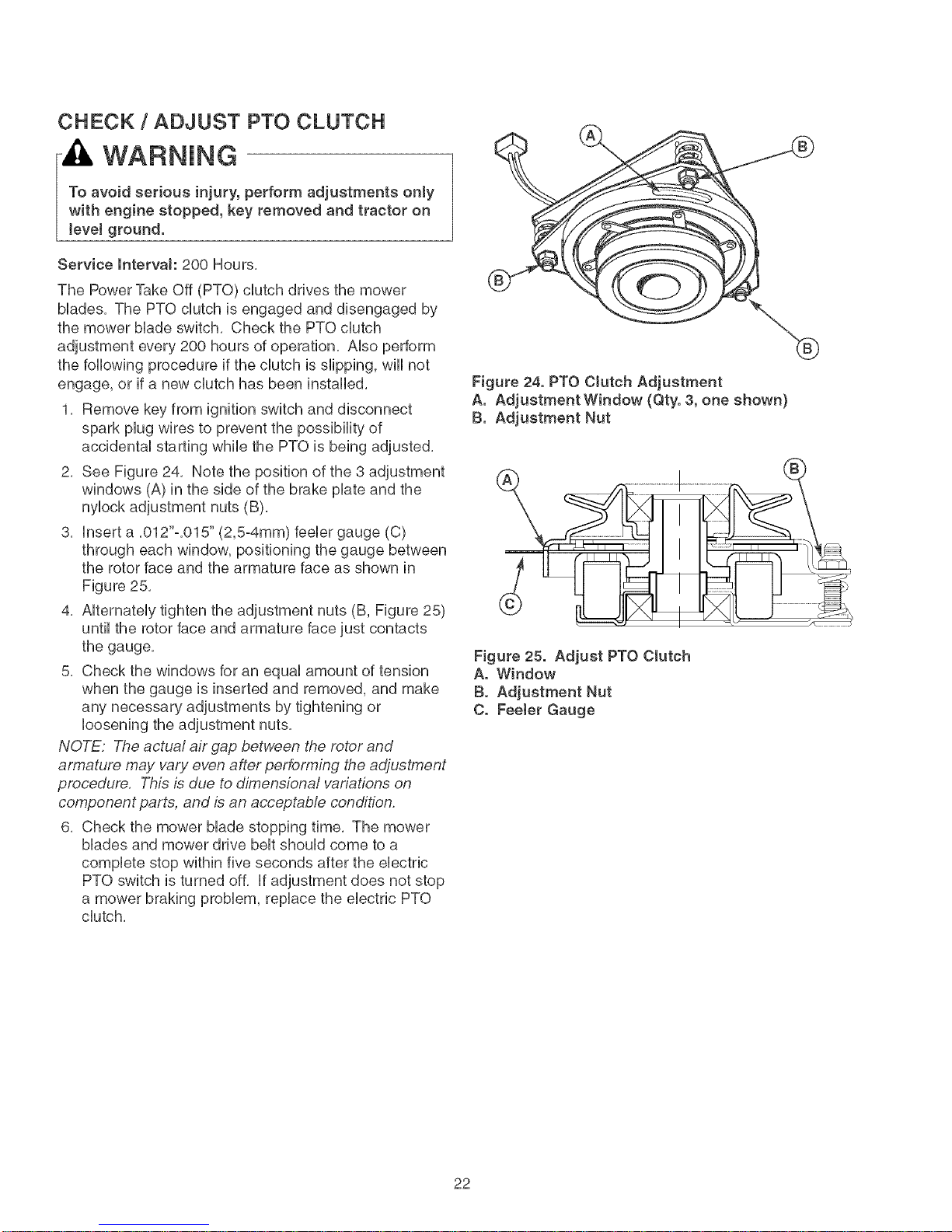
2. See Figure 24. Note the position of the 3 adjustment
windows (A) in the side of the brake plate and the
nylock adjustment nuts (B).
3. Insert a .012"o.015" (2,5-4mm) feeler gauge (C)
through each window, positioning the gauge between
the rotor face and the armature face as shown in
Figure 25,
4, Alternately tighten the adjustment nuts (B, Figure 25)
until the rotor face and armature face just contacts
the gauge.
5. Check the windows for an equal amount of tension
when the gauge is inserted and removed, and make
any necessary adjustments by tightening or
loosening the adjustment nuts.
NOTE: The actual air gap between the rotor and
armature may vary even after performing the adjustment
procedure. This is due to dimensional variations on
component parts, and is an acceptable condition.
6. Check the mower blade stopping time. The mower
blades and mower drive belt should come to a
complete stop within five seconds after the electric
PTO switch is turned off. If adjustment does not stop
a mower braking problem, replace the electric PTO
clutch.
Figure 24. PTO Clutch Adjustment
A. Adjustment Window (Qty. 3, one shown)
B. Adjustment Nut
...... iiiiiI
Figure 25. Adjust PTO Clutch
A. Window
B. Adjustment Nut
C. Feeter Gauge
22
Page 23
Engine Maintenance totems
CHECK ENGINE OiL LEVEL °
KOHLER MODELS
Service lntervak Before each use, and every 8 hours.
1. Turn the engine off, and set the ground speed
controls to PARK. Park on a level surface. Allow the
engine to cool.
2. Clean the area around the dip stick (C, Figure 27).
3,
Remove the dip stick (C) and clean it with a paper
towel.
4.
insert the dip stick back into the engine, and push
firmly into place.
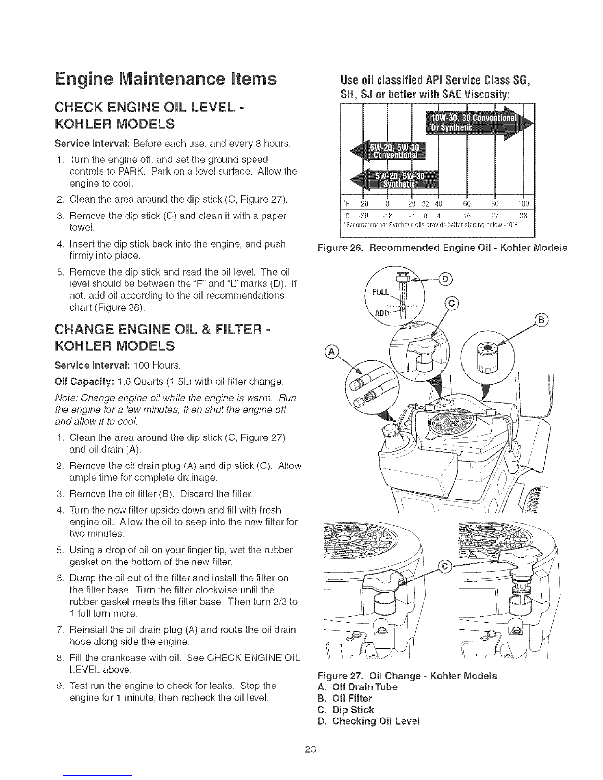
5.
Remove the dip stick and read the oil level. The oil
level should be between the "F" and "L" marks (D). if
not, add oil according to the oil recommendations
chart (Figure 26).
CHANGE ENGINE OiL & FILTER °
KOHLER MODELS
Service lntervak 100 Hours.
Use 0il classified AP_Service Class SG,
SH, SJ or better with SAEViscosity:
I
i"F -20 0 20 32 40 60 80 100
"C -30 -18 -7 0 4 16 27 38
*Recommended: Synthetic oils provide better stmling below -10°F.
Figure 26. Recommended Engine Oil - Kohter Modets
Oil Capacity: 1.6 Quarts (1.SL) with oil filter change.
Note: Change engine oil while the engine is warm. Run
the engine for a few minutes, then shut the engine off
and allow it to cool
1. Cban the area around the dip stick (C, Figure 27)
and oil drain (A),
2, Remove the oil drain plug (A) and dip stick (C), Allow
ample time for complete drainage,
8, Remove the oil filter (B), Discard the filter,
4, Turn the new filter upside down and fiii with fresh
engine oil, Allow the oil to seep into the new filter for
two minutes,
5,
Using a drop of oil on your finger tip, wet the rubber
gasket on the bottom of the new filter,
6,
Dump the oil out of the filter and install the filter on
the filter base, Turn the filter clockwise until the
rubber gasket meets the filter base, Then turn 2/3 to
1 full turn more,
7, Reinstall the oil drain plug (A) and route the oil drain
hose along side the engine,
8, Fill the crankcase with oil, See CHECK ENGINE OiL
LEVEL above,
9, Test run the engine to check for leaks, Stop the
engine for 1 minute, then recheck the oil level,
Figure 27. OH Change - Kohter Models
A. OH DrainTube
B. Oil FHter
C. Dip Stick
D. Checking Oil Level
23
Page 24
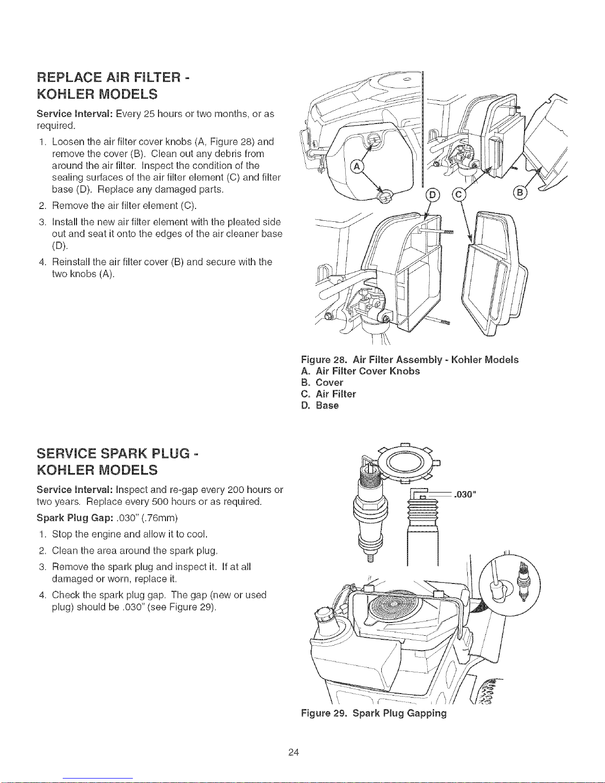
REPLACE AiR FILTER -
KOHLER MODELS
Service Interva!: Every 25 hours or two months, or as
required,
1, Loosen the air fiHtercover knobs (A, Figure 28) and
remove the cover (B), CHeanout any debris from
around the air fiHter, Hnspectthe condition of the
sealing surfaces of the air fiHtereHement (C) and fiHter
base (D), RepHaceany damaged parts,
2, Remove the air fiHtereHement (C),
3, HnstaHHthe new air fiHtereHementwith the pHeated side
out and seat it onto the edges of the air cHeaner base
(D),
4, ReinstaHHthe air fiHtercover (B) and secure with the
two knobs (A),
Figure 28. Air Filter Assembly - KoMer Models
A, Air Filter Cover Knobs
B, Cover
C, Air Filter
D, Base
SERWCE SPARK PLUG -
KOHLER MODELS
Service mntervaJ: Hnspect and re-gap every 200 hours or
two years, RepHace every 500 hours or as required,
Spark Ptug Gap: ,030" (,76mm)
1, Stop the engine and aHHowit to cool
2, CHeanthe area around the spark pHug,
3, Remove the spark pHugand inspect it, Hfat aHH
damaged or worn, repHace it,
4, Check the spark pHuggap, The gap (new or used
pHug)shouHdbe ,030" (see Figure 29),
Figure 29. Spark Plug Gapping
24
Page 25
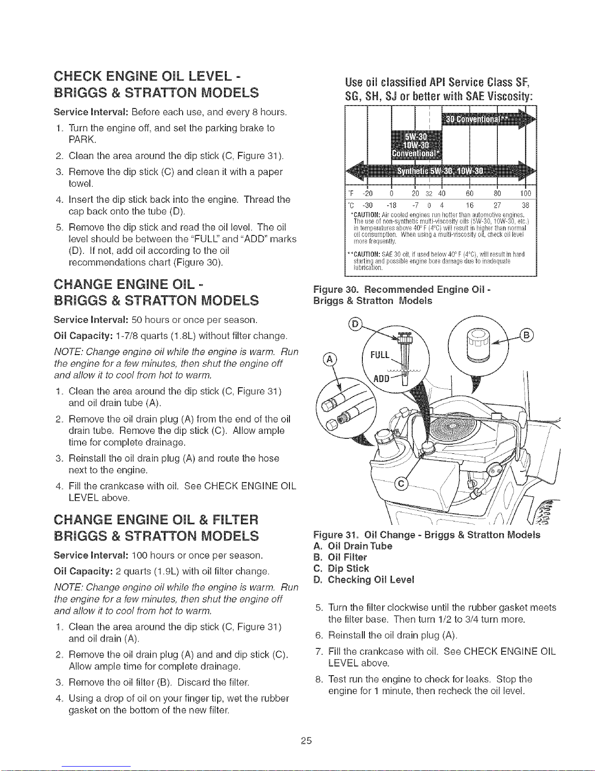
CHECK ENGINE OiL LEVEL °
BF{JGGS & STRATTON MODELS
Service intervaJ: Before each use, and every 8 hours.
1. Turn the engine off, and set the parking brake to
PARK.
2. CHeanthe area around the dip stick (C, Figure 31).
3. Remove the dip stick (C) and dean it with a paper
towel
4,
Hnsertthe dip stick back into the engine. Thread the
cap back onto the tube (D).
5.
Remove the dip stick and read the oHHeveLThe oH
HeveHshouHd be between the "FULE' and "ADD" marks
(D). ff not, add oHaccording to the oH
recommendations chart (Figure 30).
Use eli classified API Service Class SF,
SG, SH, SJ or better with SAE Viscosity:
J I J
"F -20 0 20 32 40 60 80 1
°C -30 -18 -7 0 4 16 27 38
*CNJTHON:Air cooled engines run better than automotive engines.
Tbeuse of nomsyntbetic muttiwiscosity oils (5W-30, 10W-30, etc.)
in temperatures above 40'_F:(4°0) will resultin bigher tban normal
oil consumption When using a multi-viscosity oil, cheek oil level
more frequently,
**CAUTHON:SAE30 oil, it usedbelow 40'_F (4°0), wifl result in hard
stmling and possible engine boredamage due to inadequate
lubrication
CHANGE ENGINE OiL °
BF{JGGS & STRATTON MODELS
Service intervaJ: 50 hours or once per season.
Oil Capacity: 1=7/8 quarts (1.8L) without fluterchange.
NOTE: Change engine oil while the engine b warm. Run
the engine for a few minutes, then shut the engine off
and allow it to cool from hot to warm.
1. CHeanthe area around the dip stick (C, Figure 31)
and oil drain tube (A).
2. Remove the oil drain plug (A) from the end of the oil
drain tube Remove the dip stick (C). Allow ample
time for complete drainage.
3. Reinstall the oil drain plug (A) and route the hose
next to the engine.
4. Fill the crankcase with oil. See CHECK ENGINE OIL
LEVEL above.
CHANGE ENGINE OIL & FILTER
BF{JGGS & STRATTON MODELS
Service mntervaJ: 1OOhours or once per season.
Oil Capacity: 2 quarts (1.gL) with oil filter change.
NOTE: Change engine oil while the engine is warm. Run
the engine for a few minutes, then shut the engine off
and allow it to cool from hot to warm.
1. Clean the area around the dip stick (C, Figure 31)
and oil drain (A).
2. Remove the oil drain plug (A) and and dip stick (C).
Allow ample time for complete drainage.
3. Remove the oil filter (B). Discard the filter.
4. Using a drop of oil on your finger tip, wet the rubber
gasket on the bottom of the new filter.
Figure 30. Recommended Engine Oil -
Bciggs & Stratton Modets
Figure 31. OH Change - Briggs & Stratton Modets
A. OH DrainTube
B. OH FHter
C. Dip Stick
D. Checking Oil Level
5. Turn the filter clockwise until the rubber gasket meets
the filter base. Then turn 1/2 to 3/4 turn more.
6. Reinstall the oil drain plug (A).
7. Fill the crankcase with oil. See CHECK ENGINE OIL
LEVEL above.
8. Test run the engine to check for leaks. Stop the
engine for 1 minute, then recheck the oil level.
25
Page 26
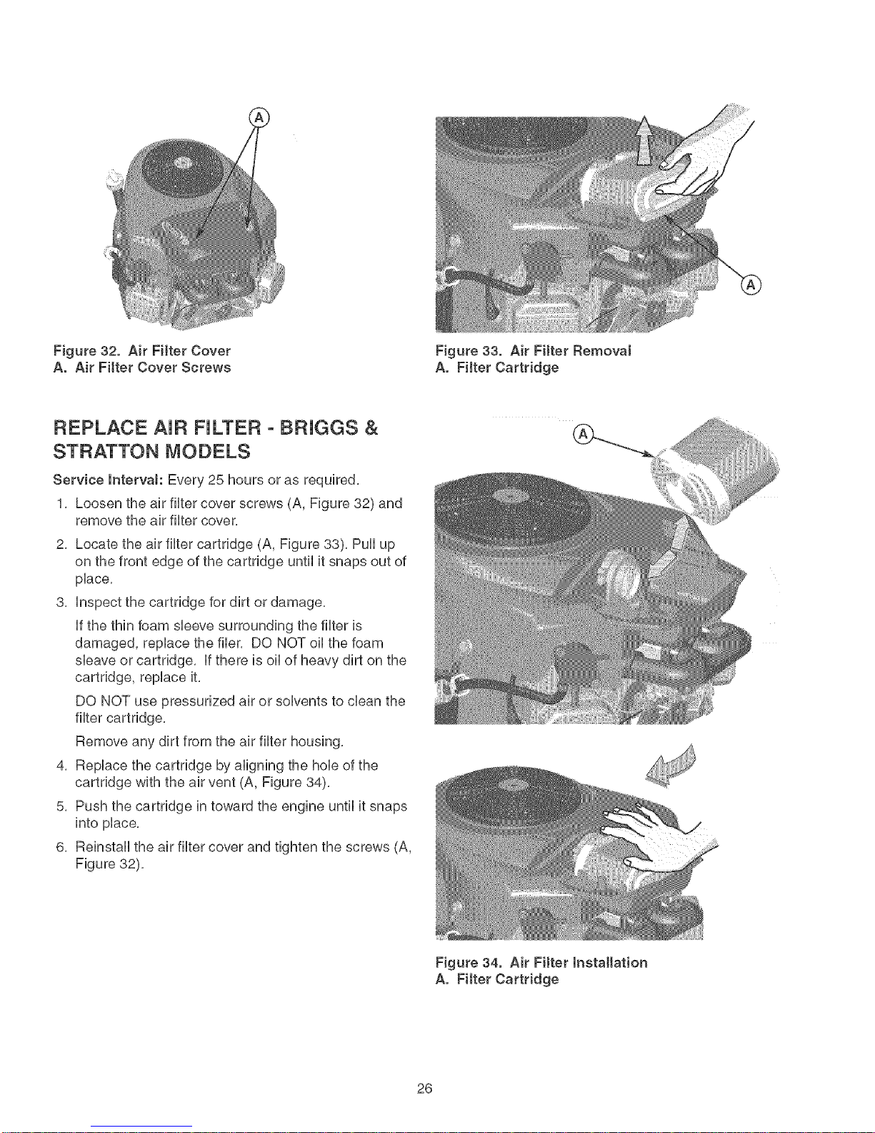
Figure32. Air Filter Cover
A. Air Filter Cover Screws
REPLACE AiR FILTER - BRJGGS &
STRATTON MODELS
Service lntervaJ: Every 25 hours or as required,
1, Loosen the air fluter cover screws (A, Figure 32) and
remove the air fluter cover,
2, Locate the air filter cartridge (A, Figure 33), Pull up
on the front edge of the cartridge until it snaps out of
pUace,
3, Unspectthe cartridge for dirt or damage,
ff the thin foam sUeevesurrounding the fluteris
damaged, repUacethe flier, DO NOT oHthe foam
sUeaveor cartridge, ff there is oHof heavy dirt on the
cartridge, replace it,
DO NOT use pressurized air or solvents to clean the
filter cartridge,
Remove any dirt from the air filter housing,
4, Replace the cartridge by aligning the hole of the
cartridge with the air vent (A, Figure 34),
5, Push the cartridge in toward the engine until it snaps
into place,
6, Reinstall the air filter cover and tighten the screws (A,
Figure 32),
Figure 33. Air FHter Removal
A. FHter Cartridge
Figure 34. Air FHter Installation
A. Fitter Cartridge
26
Page 27
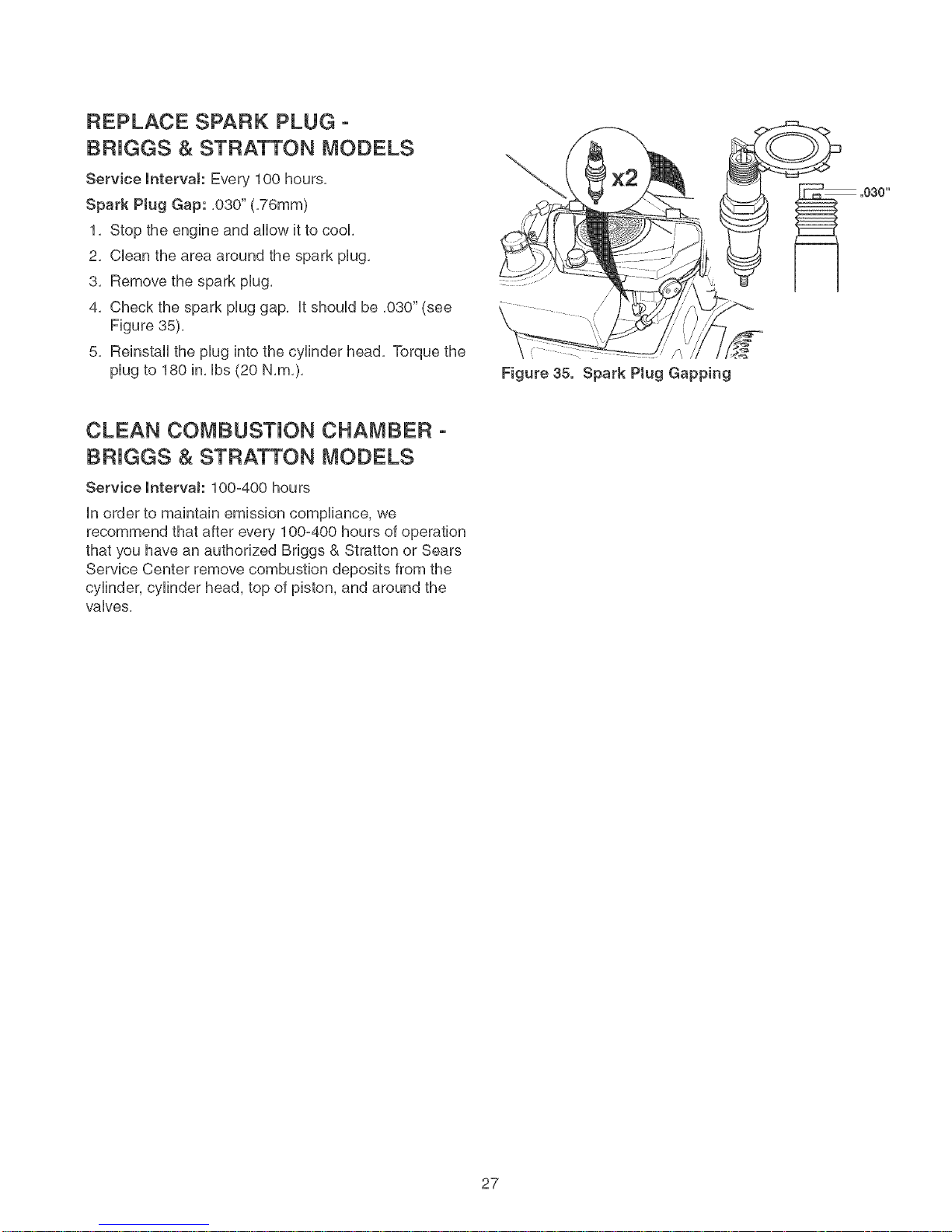
REPLACE SPARK PLUG -
BRJGGS & STRATTON MODELS
Service mnterval: Every 100 hours,
Spark Plug Gap: ,030" (,76mm)
1, Stop the engine and allow it to cool
2, CUeanthe area around the spark pUug,
3, Remove the spark pUug,
4, Check the spark pUuggap, UtshouUdbe ,030" (see
Figure 35),
5, Reinstall the pUuginto the cylinder head, Torque the
pUugto 180 in, Ubs(20 N,m,),
CLEAN COMBUSTION CHAMBER -
BRJGGS & STRATTON MODELS
Service lntervaJ: 100-400 hours
Unorder to maintain emission compliance, we
recommend that after every 100-400 hours of operation
that you have an authorized Briggs & Stratton or Sears
Service Center remove combustion deposits from the
cylinder, cylinder head, top of piston, and around the
valves,
,030"
Figure 35. Spark Plug Gapping
27
Page 28
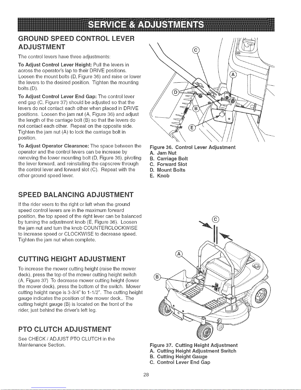
GROUND SPEED CONTROL LEVER
The control Uevershave three adjustments:
To Adjust Contro! Lever Height: Puff the Ueversin
across the operator's Uapto their DRIVE positions.
Loosen the mount bouts (D, Figure 36) and raise or Uower
the Ueversto the desired position. Tighten the mounting
boUts.(D).
To Adjust Control Lever End Gap: The control Uever
end gap (C, Figure 37) shouUdbe adjusted so that the
Ueversdo not contact each other when pUaced in DRUVE
positions. Loosen the jam nut (A, Figure 36) and adjust
the Uengthof the carriage bout(B) so that the Ueversdo
not contact each other. Repeat on the opposite side.
Tighten the jam nut (A) to Uockthe carriage boutin
position.
To Adjust Operator Clearance: The space between the
operator and the controUUeverscan be increase by
removing the lower mounting bolt (D, Figure 36), pivoting
the lever forward, and reinstalling the capscrew through
the control lever and forward slot (C). Repeat with the
other ground speed lever.
\
Figure 36. Control Lever Adjustment
A. Jam Nut
B. Carriage BoJt
C. Forward Slot
D. Mount Bolts
E. Knob
SPEED BALANCING ADJUSTMENT
If the rider veers to the right or left when the ground
speed control levers are in the maximum forward
position, the top speed of the right lever can be balanced
by turning the adjustment knob (E, Figure 36), Loosen
the jam nut and turn the knob COUNTERCLOCKWISE
to increase speed or CLOCKWISE to decrease speed,
Tighten the jam nut when complete,
CUTTING HEIGHT ADJUSTMENT
To increase the mower cutting height (raise the mower
deck), press the top of the mower cutting height switch
(A, Figure 37) To decrease mower cutting height (lower
the mower deck), press the bottom of the switch. Mower
cutting height range is 3o3/4" to 1ol/2". The cutting height
gauge indicates the position of the mower deck.. The
cutting height gauge (B) is located on the front of the
rider, just behind the driver's left leg.
PTO CLUTCH ADJUSTMENT
©
See CHECK / ADJUST PTO CLUTCH in the
Maintenance Section.
Figure 37. Cutting Height Adjustment
A. Cutting Height Adjustment Switch
B. Cutting Height Gauge
C. Control Lever End Gap
28
Page 29

BRAKE ADJUSTMENT
1, Stop the unit, turn the ignition OFF, set the ground
speed Ueversto PARK positions, and wait for aH
moving parts to stop,
2, Locate the brake rod (A, Figure 38) and adjustment
nut (B),
4, Measure the parking brake spring (E), Uts
compressed Uength,with the ground speed Ueversin
their PARK positions shouUdbe 3" (7,62cm), Adjust
the spring Uength by turning the adjustment nut (B), if
necessary,
BATTERY CHARGING
WARNING
Corrosion hazard.
Batteries contain acid. AJways keep the
battery upright and do not spill the
electrolyte. Avoid contact with skin and
eyes.
Exp!osion hazard.
Changing the battery produces expJosive
hydrogen gas. Only charge the battery in a
welt ventilated area, away from any ignition
source such as a water heater, electric
motor, or Ht cigarette.
Wear Protective Equipment
AJways wear gloves and safety glasses
when handting the battery and battery
cabJes.
Figure 38. Brake Adjustment
A. Brake Rod
B. Adjustment Nut
C. Return Spring (Removed for Illustration Onty)
D. Return Spring Hole
E. Brake Spring
A dead battery or one too weak to start the engine may
be the result of a defect in the charging system or other
electrical component, if there is any doubt about the
cause of the problem, contact a Sears Parts & Repair
Center, if you need to replace the battery, follow the
steps under Cleaning the Battery & Cables in the
Regular Maintenance Section,
To charge the battery, follow the instructions provided by
the battery charger manufacturer as well as all warnings
included in the safety rules sections of this book, Charge
the battery until fully charged (until the specific gravity of
the electrolyte is 1,250 or higher and the electrolyte
temperature is at least 60° F), Do not charge at a rate
higher than 10 amps,
ENGINE ADJUSTMENTS
The engine is designed to deliver the correct
performance under all operating conditions, Any
adjustments must be performed by a Sears or other
qualified service dealer,
29
Page 30

MOWER DECK LEVEUNG
-A WARNING
Before adjusting the mower, turn the mower
blades OFF, turn the ignition switch OFF, remove
the key, and allow aJl moving parts to stop.
Disconnect the spark plug wire and fasten it away
from the spark pJug.
Side to Side Leveling
if the cut is uneven, the mower may need bveling,
Unequal or improper tire pressure may also cause an
uneven cut, See CHECK TiRE PRESSURE,
1, With the mower installed, place the rider on a
smooth, level surface such as a concrete floor, Turn
the front wheels straight forward, Turn the engine off,
set the ground speed control levers to PARK, and
wait for all moving parts to stop,
2, Check for bent blades and replace if necessary,
3, Check the tire pressures, See CHECK TiRE
PRESSURE,
4, Set the cutting height to mid position, Arrange the
mower blades so that they are pointing from side=to=
side (Figure 40),
5, Measure the distance between the tips of the outside
blades and the ground (Figures 39 & 40), if there is
more than 1/8" (3mm) difference between the
measurements on each side, proceed to step 6, if the
difference is 1/8" (3mm) or less, proceed to Front To
Back Leveling,
6, See Figure 41, Side=to=side leveling is accomplished
using the threaded rods (A) and trunnion (B) on the
right and left rear sides of the mower deck, Loosen
the jam nuts (C) and adjust the nuts up or down to
adjust the mower level, When complete, tighten the
jam nuts against the trunnion to lock the adjustment
in place,
\
Figure 39. Measure Blade Tips to Ground
A. Mower Deck
B. Blade Tip
C. Level Ground
Figure 40. Orient Blades Side-to-Side
Figure 41. Side-to-Side Adjustment
A. Threaded Rod
B. Trunnion
C. Jam Nuts
3O
Page 31

Figure42. OrientBladesFront-to-Back
Front To Back Leveling
if the cut is uneven, the mower may need bveling,
Unequal or improper tire pressure may also cause an
uneven cut, See CHECK TiRE PRESSURE,
1, Turn the blades front-to-back as shown in Figure 42,
Measure the distance from the ground to front tip of
center blade, and from ground to rear tips of left hand
and right hand blades (Figures 39 & 42), Front tips
should be 1/8"-1/4" (3-6 mm) higher than rear tips, if
not, proceed to step 2,
2, The front mower hitch rod (A, Figure 43) is used to
adjust front-to-back leveling, To raise or lower the
front of mower deck, loosen the two rear jam nuts (B)
on both sides of the hitch rod (A), Adjust the front
jam nuts (C) on both sides of the hitch rod (A) to
adjust the deck level, When adjusted correctly,
tighten the rear jam nuts (B) to lock hitch rod in place,
MOWER BELT REPLACEMENT
Figure 43. Front-to-Back Leveling
A. Hitch Rod
B. Rear Jam Nut
C. Front Jam Nut
Mower Drive Be_t Flep_acement
1, Park the rider on a level surface, Disengage the PTO,
turn off the engine and set the ground speed control
levers to PARK, Remove the key,
2, Use the idler pulley arm (K, Figure 44) to release belt
tension and remove the mower drive belt (F) from the
PTO pulley (G),
3, Remove the belt from the remaining deck pulleys,
Note: it is not necessary to remove the mower deck,
4, Install the new belt (F) as shown in Figure 44,
Arbor Drive Be_t Flep_acement
Contact a Sears Parts & Repair Center for replacement
of the arbor drive belt (A, Figure 44),
Figure 44. PTO Bett Routing
A. Arbor Drive Belt
B. Right Arbor Pultey
C. Arbor idler Pulley
D. Center Arbor Pulley
E. Left Arbor Puttey
F. Mower Drive Bett
G. Engine PTO Pulley
H. Mower Drive Pulley
I. Mower idler Pulley
J. Backside ldter Pultey
K. ldter Puttey Arm
31
Page 32

Before Storage
Before you store your unit for the off=season, read the
Maintenance and Storage instructions in the Safety
Rules section, then perform the following steps:
o Turn the mower blades OFF, set the ground speed
control levers to START / PARK, & remove the key
from the ignition switch,
Check all fluid levels, Check all maintenance items,
o Battery life will be increased if it is removed, put in a
cool, dry place and fully charged about once a
month, if the battery is left in the unit, disconnect the
negative cable,
it is important to prevent gum deposits from forming in
the essential fuel system parts such as the carburetor,
fuel filter, fuel line, and fuel tank during storage, Also,
alcohol blended fuels (called gasohol or using ethanol or
methanol) can attract moisture which leads to the
separation and formation of acids during storage, Acidic
gas can damage the fuel system of an engine while in
storage,
WARNING
Never store the unit (with fuet) in an encJosed,
poorty ventilated structure. FueJvapors can
traveJ to an ignition source (such as a furnace,
water heater, etc.) and cause an expJosion.
FueJ vapor is aJso toxic to humans and animaJs.
To avoid engine problems use fuel stabilizer, especially
before storage of 30 days or longer,
After Storage
Before starting the unit after it has been stored:
Check all fluid levels, Check all maintenance items,
o Fill with FRESH fuel,
. After starting, allow the engine to warm before
operating,
NOTE: Specifications are correct at time of printing and are subject to change without notice.
ENGINE:
Make
ModeR
Horsepower*
Displacement
Electrical System
Oil Capacity
Make KoMer
Model SV600S Type
Horsepower 20 @ 3600 rpm* Hydraulic Fluid
Displacement 38=4 Cu=in (897 cc) Continuous Torque
Electrical System 12Volt, 18 amp. Alternator, Battery: 340 CCA Output
OH Capacity 1.6 qt (! .5 L) w filter change Ma×imum Weight
_Briggs & Stratton Models: The gross po#'er rating for individual gas engine models is labeled in accordance with SAE (Society of
Automotive Engineers) code J1940 (Smafl Engine Power & Torque Rating Procedure), and ratLogperformance has been obtaLned
and corrected Lnaccordance with SAE J1995 (Revision 2002-05), Torque values are derived at 3060 RPM; horsepower values are
derived at 3600 RPM, Actual gross engine power #;qlbe lower and is affected by, among other thLngs, ambient operating conditions
and engine-to-engine van',sbility, Given both the wide array of products on #;hich engines are placed and the variety of
environmental issues appficable to operating the equipment, the gas engine w_flnot develop the rated gross power #'hen used in a
given piece of power equipment (actual "on-site" or net horsepower), T,his difference is due to a variet:y of factors including, but not
limited to, accessories (air cleaner, exhaust, charging, coofing, carburetor, fuel pump, etc,), application fimitations, ambient
operating conditions (temperature, humidity, altitude), and engine-to-engine variability, Due to manufacturing and capadty
limitations, Briggs & Stratton may substitute an engine of higher rated power for this Series engine,
Briggs & Stratton
Intek
24 @ 3600 rpm*
44.2 Cu. in (725cc)
12 Volt, !8 amp. Alternator, Battery: 340 CCA
64 Oz. (1.9L)
Fuel Tank
Rear Wheels
Front Wheels
on Axle
Capacity: 3.25 Gallons (12,3 L)
Tire Size: 18 x 8.8 -8
Inflation Pressure: 10-12 psi (,69-,83 bar)
Tire Size: ! 1 x 4-5
Inflation Press.: 18-20 psi (1,24-1,30 bar)
Hydro-Gear EZT ZC-AHBB-2A7B-1DPX
20w 80 Premium Engine Oil
115 fL Ibs.
340 Ibs
32
Page 33

While normal care and regular maintenance will extend the life
of your equipment, prolonged or constant use may eventually
require that service be performed to allow it to continue
operating properly. The troubleshooting guide below lists the
most common problems, their causes and remedies.
If you prefer, all of these procedures can be performed for you
by a Sears Parts & Repair Center. See the back cover for
important Sears Parts & Repair Center information.
WARNING
To avoid serious injury, perform maintenance on
the rider or mower onty when the engine is
stopped and the ground speed tevere are set to
PARK.
Always remove the ignition key, disconnect the
spark pJug wire and fasten it away from the plug
before beginning the maintenance, to prevent
accidentaJ starting of the engine.
TrouMeshooting the Rider
PROBLEM CAUSE REMEDY
Engine will Ground speed levers not set to START/PARK, Set to START/PARK,
not turnover Mower blade switch in ON position, Place in OFF position,
or start.
Engine starts Air filter plugged Service pre-cleaner and/or replace air filter
hard or rune element,
poorly. Choke not set to CLOSED position when Set choke to CLOSED when cranking, Set choke to
Ground speed levers not set to START/PARK, Set to START/PARK
Choke not in CLOSED position, Move choke to CLOSED position,
Ignition switch not turned fully to START position, Turn ignition switch fully to START position,
Out of fuel, Allow engine to cool, then refill the fuel tank,
Set choke to OPEN position when cranking engine,
Fuel is old or stale, or water in fuel, Drain fuel & replace with fresh fuel, Contact Sears
Parts & Repair,
Battery terminals require cleaning, Clean the battery terminals
Battery discharged or dead, Recharge or replace,
Spark plug(s) faulty, fouled or incorrectly gapped, Clean and gap or replace,
Wiring loose or broken, Visually check wiring & replace broken or frayed
wires, Tighten loose connections,
Solenoid or starter motor faulty, Replace, Contact Sears Parts & Repair,
Safety interlock switch faulty, Replace, Contact Sears Parts & Repair,
cranking the engine, OR choke not set to OPEN OPEN when engine is running, A warm engine may
after engine starts, not require choking,
Spark plug faulty, fouled, or incorrectly gapped, Clean and gap or replace,
Engine Low oil level, Check/add oil as required,
knocks. Using wrong grade oil, See "Change Engine Oil" in the Maintenance
Excessive oH Engine running too hot, Clean engine cooling fins, blower screen and air
consumption cleaner,
Using wrong weight oil, See "Change Engine Oil" in the Maintenance
Too much oil in crankcase, Drain excess oil,
Engine Dirty air filter or pre°cleaner, or both, Service or replace as required, See Maintenance
exhaust is Section,
black. Choke set to CLOSED when engine is running, Set choke to OPEN as soon as engine starts,
Section,
Section,
33
Page 34

Engineruns,but
riderwiltnot
drive.
Riderdrivebelt
sJips.
Parkingbrake
will nothold.
TransmissionreleasebversinPUSH
3ositions,
T:)rivebeltslips,
Beltisbroken,
Parkingbrakeisnotfullyrebased,
Pulbysorbeltgreasyoroily,
Beltstretchedorworn,
Parkingbrakeisincorrectlyadjusted,
MoveleverstoDRIVEpositions,
Cleanorreplacebeltasnecessary,
Replacedrivebelt,ContactSearsParts& Repair,
ContactSearsParts&Repair,
Cleanasrequired,
Replacebelt,ContactSearsParts&Repair,
SeeService&AdjustmentsSection,
Ridersteersor
handbspooHy.
Ridertracksto
one side.
Troubleshooting
PROBLEM
Mower cutting
height difficult to
adjust.
Mower cut is
uneven.
Mower cut is rough
tooking.
impropertireinflation,
Steeringlinkageisloose,
Groundspeedadj,knobsnotadjusted,
the Mower
CAUSE
Cutting height motor screw dirty or
Cutting height linkage disconnected,
Rider tires not inflated equally or properly,
Mower not leveled properly,
Engine speed too slow,
Ground speed too fast,
Blades are dull,
Mower drive belt slipping because it is oily
or worn,
Blades not properly fastened to arbors,
SeeMaintenanceSection,
Checkandtightenanylooseconnections,
SeeSPEEDBALANCINGADJUSTMENTintheService
&Adjustmentssection,
REMEDY
Thoroughly clean and lubricate cutting height crank
with oil,
Reconnect cutting height linkage
See Maintenance Section,
See "Mower Leveling" in Service & Adjustments,
Always set throttle to FULL when mowing,
Decrease ground speed,
Sharpen or replace blades, See Maintenance
Section,
Clean or replace belt as necessary,
See "ChecWReplace Mower Blades" in
Maintenance Section,
Engine stalls easity
with mower
engaged.
Excessive mower
vibration.
Mower drive beJt
stips or faits to
drive.
Engine speed to_ slow,
Ground speed too fast,
Cutting height set too low,
Underside of mower deck dirty,
Discharge chute jamming with cut grass,
Blade mounting bolts are loose,
Mower blades, arbors, or pulleys are bent,
Mower blades are out of balance,
Belt installed incorrectly,
Idler pulley spring broken or not properly
attached,
Mower drive belt broken,
PTO clutch out of adjustment,
Always set throttle to FULL when mowing,
Decrease Ground Speed,
Cut tall grass at maximum cutting height during first
:)ass,
Remove mower deck and clean underside,
Cut grass with discharge pointing toward previously
cut area,
Tighten to 45°55 ft, Ibs, (61o75 N,m,),
Check and replace as necessary,
Replace or balance blades, See Maintenance
Section,
Reinstall correctly,
Repair or replace as needed,
Replace drive belt,
Adjust PTO clutch, See Maintenance Section,
34
Page 35

Due o
ZTS 7500
Gire a cero los montables posteriores del motor con
el arranque electrico
No. de modelo
107.27772 (20HP Kohler con segadora de 44")
107.27774 (22HP Briggs & Stratton con segadora de 50")
PRECAUCI6N: Este producto tiene un mot
or con expuWsi6n baja el cual funciona difer-
entemente a otros motores. Antes que
arranque el motor, Weay comprenda el
Manual del Due_o.
Para obtener respuestas a cualquier pregunta
sobre este producto, llame al numero de tele-
fono-(sin cobro) siguiente:
1°800-659-5917
Servicio de ayuda Sears Craftsman
5 am o5 pro, Lunes a Sabado
35
Page 36

Deciaraci6ndeGarant{a...........................................36
Reg[as e informaci6n de Segur[dad ........................ 37
NQmeros de identificaci6n ........................................ 42
Accesorios Opciona[es ............................................. 42
Contenido de[ Paquete de L[teratura ....................... 42
Pre-Operac[6n ............................................................ 43
Operaci6n ................................................................... 44
Mantenimiento ........................................................... 51
Servicio y Ajustes ...................................................... 62
Aimacenamiento ........................................................ 66
D[agn6st[co ................................................................ 67
Partes de Refacci6n ............................................ PTS-1
Hardware y Especificaciones de[ Esfuerzo de
Torsi6n ............................................................... PTS-39
Repare E[ Acuerdo De [a
Protecci6n .................... Dentro De [a Cubierta Trasera
Mantenga Los NQrneros De
Phono ................................................. Cubierta Trasera
NOTA: En este manual "izquierda" y "derecha" se refieren segdn como se vea desde la posicidn de operacidn.
GARANTiA UMFADA DEL EQUPO MONTABLE DE CRAFTSMAN
Por dos (2) aSos a partir de la fecha de compra, si este equipo montabb de Craftsman es mantenido, lubricado y afinado
conforme alas instrucciones en el manual del propietario, Sears reparara o reemplazar4 sin costo alguno cualquier parte
que se encuentre defectuosa en material o mano de obra conforme a los lineamientos de la cobertura enumerada a contino
uaci6n. Sears tambi6n proporcionara mano de obra gratis por las partes garantizadas que apliquen durante estos dos aSos
compbtos. Durante los primeros 30 d{as de compra, no habra cargos para dar servicio al producto en su domicilio por
probbmas cubiertos pot esta garant{a. (Vea las excepciones abajo). Para su conveniencia, el servicio de garantia A DOMb
CIUO seguira estando disponibb despues de los primeros 30 dias de compra, pero habr4 uncargo pot el recorrido. Este
cargo quedara anulado si se Ileva el producto Craftsman en uno de los lugares autorizados de Sears. Para averiguar cu41
es el Sears mas cercano a usted, b rogamos que Ilame a lo800oMYoHOME.Esta garant{a aplica s61omientras el producto
este dentro de los Estados Unidos.
ESTA GARANTiA NO CUBRE:
Articuios consumibies que se desgastan con e[ uso
normal 1oque inciuye, entre otros [as aspas, bujias, fi[o
tros de aire, bandas y fiitros de aceite.
• Servicio por mantenimiento est_.ndar, cambios de
aceite y afinaciones.
• Reempiazo o reparaci6n de [[antas causado por porto
chaduras de objetos externos, como ciavos, pOas,
troncos cortados o vidrio.
ador, 1oque inciuye, entre otros, daSos e[ectricos y
mecb,nicos causados por e[ aimacenamiento inadecuao
do, no usar e[ grado y [acantidad adecuada de aceite
para motor, no mantener [a cubierta [ibre de despojos
inflamabies o no mantener e[ equipo conforme a [as
instrucciones contenidas en e[ manual de[ propietario.
La [impieza de[ motor (instaiaci6n de combustible) o
reparaci6n causada por gasoiina que se decide est,.
contaminada u oxidada (viciada). En genera[, e[ como
Las reparaciones necesarias por abuso de[ operador,
1oque inciuye, entre otros, daSos causados por remo[o
bustibie debe usarse en un [apso de 30 dias de su
fecha de compra.
car objetos que sobrepasan [as capacidades de[
equipo montabie, impacto contra objetos que dobien e[
bastidor o cigOeSa[ o exceder [a veiocidad de[ motor.
Las reparaciones necesarias por negiigencia de[ opero
GARANTiA LIMITADA DE LA BATERiA
Por noventa (90) d{as a partir de la fecha de compra, si la bateria incluida con este equipo montable prueba estar defectu o
osa en material o mano de obra y nuestras pruebas determinan que la bateria no retiene la carga; Sears reemplazara la
bater{a sin cargos. Durante los primeros 30 d{as de compra, no habra cargos para reemplazar la bater{a en su DOMICILIO.
Despues de los primeros 30 d{as, para su conveniencia, el servicio de garant{a A DOMICILIO seguira estando disponible,
pero habra un cargo pot el recorrido. Este cargo quedara anulado si se lleva el producto Craftsman en uno de los lugares
autorizados de Sears. PARA AVERIGUAR CUA, L ES EL SEARS MA,S CERCANO A USTED, LE ROGAMOS QUE LLAME
A lo800oMYoHOME. Esta garant{a de la bater{a aplica s61o mientras el producto este dentro de los Estados Unidos.
Esta garant{a le otorga derechos legales espec{ficos, pero es posible que usted tenga otros derechos, los cuales vat{an de
un estado a otro.
E[ deterioro y desgaste normal de los acabados de[
exterior ni e[ reempiazo de [as etiquetas de[ producto.
Cuando e[ equipo montabie que se usa con fines coo
merciaies o de aiquiier.
Sears, Roebuck and Co., Dept. 817WA, Hoffman Estates, iL 60179
36
Page 37

LeaestasregUasdeseguridadysigaUasconcuidado,NoobedecerestasregUaspuedeocasionarUap6rdida
delcontrolsobrelaunidad,lesionesseverasalapersonao lamuertedeusted,o espectadores,oda_osa la
)iedado alequipo,Esta cubierta de Japodadora es capaz de amputar manos yj_ies y de arro'aEa[
_etos. El tri_.ngulo _ en el texto denota precauciones o advertencias importantes que deben obedecerse,
OPERACI6N GENERAL
1. Lea, entienda y siga todas Ias instrucciones en el manual y
en la unidad antes de arrancar.
2. No coioque Ias manes o pies cerca de las partes giratorias o
debajo de Ia ma.quina. Mantengase aIejado de la abertura
de expulsi6n en todo momento.
3. $61o permita que un adulto responsable, que este familiariza-
do con Ias instrucciones, opere la unidad (los reglamentos
locales pueden restringir Ia edad del operador).
4. Retire deI area objetos tales come piedras, juguetes, etc,
que pueden set cogidos y arrojados per las aspas.
5. Aseg_rese de que el area este libre de otra gente antes de
podar el cesped. Detenga la unidad si alguien entra en el
4rea.
6. Nunca Ileve pasajeros.
7. No pode el cesped en reversa a menos que sea absoluta-
mente necesario. Siempre mire hacia abajo y hacia atras
antes de echarse en reversa y mientras !o hace.
8. Nunca descargue el material directamente hacia alguien.
Evite descargar el material contra una pared u obstrucci6n.
El material puede rebotar hacia el operador. Detenga Ias
aspas cuando cruce per superficies cubiertas de grava.
9. No opere la maquina sin el recogedor completo de hierba,
guarda de descarga (deflector) ni otros dispositivos de
seguridad en su lugar y operacionales.
10. Baje JaveJocidad antes de dar Javuelta.
11. Nunca deie la unidad operando sin supervisi6n. Siempre
desacople las cuchilIas (PTO), ponga el freno de mane,
detenga el motor y quite Jas Ilaves antes de desmontar.
12. Desacople Ias cuchillas (PTO) cuando no est6 podando el
c6sped. Apague el motor y espere a que todas Ias partes
se detengan per complete antes de limpiar la maquina,
quitar el recolector de hierba o desatascar la guarda de Ja
descarga.
13. Opere Ia maquina s61o a Ja Iuz deI dia o con buena Juz arti-
ficial.
14. No opere la unidad si usted est_ bajo Ia infiuencia de alco-
hol o drogas.
15. Tenga cuidado con el trafico si opera cerca de alguna calle.
16. Sea extremadamente cuidadoso al cargar o descargar Ia
unidad en un remolque o camioneta.
17. Siempre protejase los ojos cuando opere esta unidad.
18. Los dates indican que operadores, de 60 aFsosy mas, estan
involucrados en un gran porcentaie de IesJones asociadas
con equipos motorizados. Estos operadores deberian evaP
uar su habilidad de operar el equipo con Ia suficiente
seguridad para protegerse a si mismos y a otros de
Iesiones.
19. Siga las recomendaciones del fabricante respecto a los
pesos y contrapesos para Ilantas.
20. Recuerde que el operador es responsable de los accP
dentes que ocurran a otra gente o propiedad.
21. Todos los conductores deberian pedir y obtener instruc-
ciones profesionales y practicas.
22. Siempre use zapatos cerrados y pantalones. Nunca opere
Ia unidad descalzo o usando sandalias.
23. Antes de su uso, siempre verifique visualmente que Ias
cuchilIas y sus aditamentos esten presentes, intactos y aft-
anzados. Reemplace Ias partes daF_adaso desgastadas.
24. Desacople los accesorios antes de: cargar combustible,
retirar un accesorio, hacer ajustes (a menos de que el
ajuste pueda hacerse desde el puesto del operador).
25. Cuando la maquina est_ estacionada, almacenada o se
deia sin supervisi6n, baje los medios de corte a menos de
que use una traba mecanica positiva.
26. Antes de dejar et puesto del operador per cualquier raz6n,
accione el freno de mane (si viene equipado con uno),
desacople Jascuchillas (PTO), detenga el motor y quite Ja
JJave.
27. Para reducir el peligro de incendio, mantenga la unidad Iibre
de cesped, hojas y aceite excesivo. No se detenga ni esta-
cione sobre hojas secas, cesped o materiates com-
bustibles.
28. Usar u operar un motor sobre o cerca de tierras cubiertas
de bosques, matorrales o cesped es una violaci6n de Ja
Secci6n 4442 del ©6digo de RecuFsos PSbticos de
California a menos que el sistema de escape este equipa-
do con un parachispas que cumpta con Ias byes locales o
estatales aplbabtes. Es posible que otras 6.reas estatales o
federales tengan Ieyes similares.
29. Las regulaciones dei OSHA pueden requerir ei uso de Ia
protecci6n de oido cuando est_n expuestas a los niveles de
sonido mayor DBA de 85 per un periodo de 8 horas.
exceso de DBA 85 en el oido deJ operador y puede
Esta maquina produce niveles de sonido en el
causar periodos sin embargo protongados de la
perdida de oido de Ia exposici6n.
Protecci6n de oido del desgaste aI funcionar esta maquina.
TRANSPORTE Y ALMACENAMIENTO
1. Cuando se transporta la unJdad sobre un remolque abierto,
asegOrese de que mire hacia el frente, en direcci6n del
desptazamiento. Si la unidad esta mirando hacia atFas, la
fuerza del aire puede daF_arIa unidad.
2. Siempre obedezca las practicas seguras para cargar com-
bustible y manejar combustible al cargar la unidad con
combustible despues deI transporte o almacenamiento
3. Nunca almacene la unidad (con combustible) en una estruc-
tufa cerrada con poca ventilaci6n. Los vapores del com-
bustible pueden viajar a una fuente de ignici6n (como un
homo, calentador de agua, etc.) y ocasionar una expJosi6n.
TP 625o4103o01 oZToUV
Los vapores de! combustible tambien son t6xicos para los
humanos y animales.
4. Siempre siga las instrucciones deI manual del motor respec-
to a Ias preparaciones de almacenamiento antes de alma-
cenar Ia unidad ya sea per periodos cortes o largos.
5. Siempre siga las instrucciones del manual del motor respec-
to a los procedimientos apropiados de arranque cuando
reintegre Ia unidad aI servicio.
6. Nunca almacene la unidad ni el contenedor de combustible
en un Iugar cerrado, donde haya una llama abierta o piloto,
como sucede con un calentador de agua. Permita que la
unidad se enfrie antes de almacenarla.
37
Page 38

OPERACI6N EN CUESTAS
Las cuestas son un factor importante relacionado con los acci-
dentes pot perdida de controt y votcaduras, y pueden propiciar
lesiones severas o Ia muerte. Cualquier operaci6n en cuestas
exige precauciones extremas. Si usted no puede dar marcha
atras en una cuesta o se siente inquieto en ella, no opere en
ella.
No se puede recuperar el control de una maquina de empujar
o montable que se desIiza por una cuesta accionando el freno.
Las principales razones de p6rdida de control son: agarre
insuficiente de Ias Ilantas en Ia tierra, vetocidad demasiado
alta, frenado inadecuado, ei tipo de maquina es inadecuada
para la labor, falta de conocimiento sobre las condiciones de la
tierra, enganche y distdbuci6n de la carga incorrectos.
1.Pode el cesped de la cuesta de arriba hacia abajo y viceversa,
no de un lado al otro.
2.Tenga con cuidado con los baches, raices o topes. Un terreno
accidentado puede volcar la unidad. El cesped alto puede
ocultar obstaculos.
3. Opte por una velocidad lenta de modo que no tenga que
detenerse o camblar de velocidad mientras este en la cuesta.
4. No pode cesped mojado. Las Ilantas pueden perder la trac-
ci6n.
5. Evite arrancar, detenerse o dar la vuelta sobre una cuesta. Si
las Ilantas pierden traccl6n (es decir, la maquina detlene el
movimiento hacia adelante en una cuesta), desacopte las
cuchillas (PTO) y conduzca lentamente hasta salir de la cues-
ta.
6. Mantenga todos los movimlentos en la cuesta lentos y grad-
uales. No haga cambios bruscos de velocidad o direcci6n,
pues esto podria hacer que se vuelque la maquina.
7. Extreme precauciones mientras opere maquinas con recotec-
totes de hierba u otros accesorlos; estos pueden afectar la
estabilidad de la unldad. No los use en cuestas pronunciadas.
8. No [ntente establlizar la maquina poniendo el pie en el piso (en
unldades montabtes).
9. No pode el cesped cerca de barrancos, zanjas o diques. La
podadora podria volcarse repentlnamente si una Ilanta cae
por la orilla de un acantilado o zanja o si se derrumba una
orilia.
10. No use los recolectores de hlerba en cuestas pronuncladas.
11. No pode el cesped en cuestas en las cuales no pueda dar
marcha atras.
12. Consulte con su dlstribuidor o concesionario autorizado
respecto a recomendaciones sobre pesos o contrapesos
para llantas para mejorar la establlidad.
13. Quite obst_culos tales como piedras, ramas de arboles, etc.
14. Use la ve!ocidad lenta. Las llantas pueden perder la traccl6n
en las cuestas aun cuando los frenos funcionan deblda-
mente.
15. No de vuelta en una cuesta a menos de que sea necesario, y
entonces, gire lenta y gradualmente cuesta arriba, si es posl-
ble. Nunca pode el cesped cuesta abajo.
EQUIPO REMOLCADO (UNIDADES MONTA°
BLES)
1.SoIamente remotque aquellas maquinas que tienen un
enganche diseffado para remolcar. No enganche el equipo
remotcado excepto en el punto del enganche.
2. Siga las recomendaclones del fabrlcante respecto al Fmite
de peso para el equipo remolcado y el declive de remolca-
do. Vea enganchar un remolque en la secci6n de
OPERACION.
3. Nunca permita que los nifios u otros se suban o metan al
equipo remolcado.
Nunca opere en cuestas mayores a 17,6 por c[ento
(10 °) UocuaUes una [ncHnac[6n de 3 1/2 pies (106 cm)
verticaUmente en 20 pies (607 cm) horizontalmente
Opte por una velocidad lenta antes de subir la
cuesta, Extreme precauciones al opere en cuestas
con un recolector de cesped montado en la parte
trasera,
Pode el cesped de la cuesta de arriba hacia abajo y
viceversa, no de un lado al otro, Extreme
precauciones al cambiar de direcci6n y NO
ARRANQUE NI SE DETENGA EN LA CUESTA,
4. En Ias cuestas, el peso deI equipo remolcado puede oca-
slonar p6rdida de tracci6n y perdida de control.
5. Trasladese lentamente y conceda una distancia adlcionaI
para frenar.
6. No cambie a neutral para destizarse cuesta abajo.
NINOS
Pueden oourrff accidentes tragicos s[ el operador no esta aIerta a
la presencia de nifios. Los nifios con frecuencia se yen atraidos
por la unidad y Ia poda de cesped. Nunca suponga que los nlfios
se quedar6.n donde usted los vio Ia Qltima vez.
1. Mantenga a los nifios Iejos del area de poda deI cesped y bajo
el cuidado atento de otto adulto responsable.
2. Est6 alerta y apague la unidad si los nifios entran al area.
3. Antes y durante Ia operaci6n en reversa, mire hacia atras y
abaio por sl hay nifios pequefios.
4. Nunca Ileve nifios, ni slquiera con las cuchillas apagadas.
Estos pueden caerse y salir gravemente heridos o interferff
con Ia operacl6n segura de la unidad. Los nifios que reci-
bieron un paseo anterlormente pueden aparecer repentlna-
mente en e! area de poda del c6sped para que les den otto
paseo y ser atropetlados por la mAquina.
5. Nunca permita que un nifio opere Ia unidad.
6. Extreme precauciones cuando se acerque a esquinas fuera de
su angulo de visl6n, arbustos, arboles u otros obietos que
pueden obstruff la vlsi6n.
EMISlONES
1. Se descubr[6 que Ias emisiones deI motor de este producto
contienen quimlcos que, en ciertas cantidades, causan
c_ncer, defectos de nacimiento u otros dafios reproduc-
tlvos.
2. Busque la [nformaci6n relevante sobre el Periodo de
Durabilldad de las Emisiones e indice del Aire en las eti-
quetas de emislones del motor.
SlSTEMA DE ENCENDIDO
1. Este sistema de encendido pot chispa cumple con ICES-002
de Canad&
38
Page 39

SERVICIO Y MANTENIMIENTO
Manejo Seguro de maGasolina
1=Apague cigarros, puros, pipas y otras fuentes de ignici6n.
2. Use s61olos contenedores aprobados para gasolina.
3. Nunca quite eI tap6n de Ia gasolina ni cargue combustible
con el motor encendido. Permita que el motor se enfrie
antes de poner combustible.
4. Nunca cargue combustible para la maquina en espacios cer-
fades.
5. Nunca almacene la maquina ni el contenedor de combustible
donde haya una llama abierta, chispa o piloto, come cerca
de un calentador de agua u otro dispositivo.
6. Nunca Ilene Ios contenedores dentro de un vehfculo o en la
caja de una camioneta con cobertor de plat6n de plAstJco.
Siempre coloque los contenedores en el piso, bjos de su
veh[culo antes del relbnado.
7. Retire el equipo accionado per gasolina de Ia camioneta o
remolque y cargue el combustible estando eI equipo en el
piso. Si esto no es posible, entonces cargue el combustible
en el equipo colocado en el remolque con un contenedor
portatil, en vez de usar un dispensador de gasolina.
8. Mantenga el dispensador en contacto con Ia orilla dei tanque
de gasolina o con Jaabertura del contenedor en todo
momento hasta que termine de cargar combustible. No use
un dispensador con un dispositivo de cerrado y abierto.
9. Si derrama combustible sobre la ropa, cb.mbiese de ropa de
inmediato.
10. Nunca Ibne demasiado eI tanque de gasolina. Coloque
nuevamente el tap6n de ia gasolina y aprietelo fijamente.
11. Extreme precauciones en ei manejo de ia gasolina y otros
combustibles. Son infiamabIes y los vapores son expJo-
sivos.
12. Si se derrama combustible, no intente arrancar eI motor
sine mas bien mueva Ia maquina bjos del Area de derrame
y evite crear cualquier fuente de ignici6n hasta que se
hayan disipado los vapores deI combustible.
13. Vuelva a colocar fijamente las tapas del tanque de gasolina
y las tapas deJcontenedor del combustible.
Servicio y Mantenimiento
1. Nunca ponga en marcha Ia unidad en un Area cerrada donde
se pueden acumular los gases del mon6xido de carbono.
2. Mantenga apretadas las tuercas y pernos, en especial los
pernos de ajuste para las cuchiJlas, y mantenga el equipo
en buenas condiciones.
3. Nunca manipule Ios dispositivos de seguridad. Verifique su
operaci6n adecuada con regularidad y asegQrese de hacer
las reparaciones necesarias si no funcionan debidamente.
4. Mantenga Ia unidad libre de cesped, hoias u otra acumu-
laci6n de despojos. Limpie derrames de aceite o com-
bustible y quite cualquier despoio impregnado de com-
bustible. Siempre permita que su maquina se enfrie antes
de almacenarla.
5. Detenga e inspeccione Ia maquina, si pega contra un objeto.
Repare, si es necesario, antes de volver a arrancar.
6. Nunca haga ajustes ni reparaciones con el motor encendido.
7. Verifique los componentes del recolector de hierba y Ia guar-
da de Ia descarga con frecuencia y reemplacelos con Ias
partes recomendadas por el fabricante, cuando sea nece-
sario.
8. Las cuchillas de la podadora estb_nafiladas. Envuelva Jas
cuchilIas o utilice guantes, y extreme precauciones cuando
bs de mantenimiento.
9. Verifique la operaci6n de los frenos con frecuencia. Ajuste y
de mantenimiento segun se requiera.
10. Mantenga o reemplace Ias etiquetas de seguridad y de
instrucciones segOn sea necesario.
11. No quite ei filtro de Ia gasolina cuando el motor estA
caliente ya que la gasolina que se derrame se puede incen -39
diar. No extienda Ias abrazaderas de Ia tuberia deI com-
bustible mas alIA de Io necesario. AsegOrese de que las
abrazaderas agarren firmemente la manguera sobre el fiJtro
despu6s de Ia instalaci6n.
12. No use gasotina que contenga METANOL, gasohol con mas
de110% de ETANOL, aditivos para gasotina ni gas blanco
porque podria ocasionar daBos aI motor o a Ia instalaci6n
del combustible.
13. Si debe drenar el tanque de gasolina, debe hacerJo al aire
libre.
14. Reemptace Ios silenciadores/mofies defectuosos.
15. Mantenga o reemplace las etiquetas de seguridad y de
instrucciones segQn sea necesario.
16. Use s61o las partes de repuesto autorizadas de f_brica al
reparar Ia unidad.
17. Siempre acate las especificaciones de fb,brica respecto a
todas Ias disposiciones y aiustes.
18. $61o acuda a lugares autorizados de servicio si requiere de
servicio y reparaciones mayores.
19. Nunca intente hacer reparaciones mayores en esta unidad
a menos que tenga Ia preparaci6n para ello. Los proced-
imientos inadecuados de mantenimiento pueden ocasionar
peligros en Ia operaci6n, daFios al equipo y anulaci6n de la
garantia del fabricante.
20. En las podadoras con cuchilIas mQItiples, tenga cuidado ya
que hacer girar una cuchilIa puede hacer que otras
cuchilIas tambien giren.
21. No cambie el limitador de velocidad del motor ni acebre
demasiado eI motor. Operar et motor a una velocidad exce-
siva puede aumentar los peligros de lesiones a la persona.
22. Desacople los accesorios de conducci6n, detenga el motor,
quite la Ilave y desconecte eI cable de la bujia antes de:
desatorar obstrucciones en accesorios y tolvas, dar man-
tenimiento a Ia unidad, pegarle a un obieto o si Ia unidad
vibra de modo anormal. Despues de pegarle a un obieto,
inspeccione la maquina para ver si rue da_ada y haga Ias
reparaciones antes de volver a arrancar y operar et equipo.
23. Nunca coloque sus manos cerca de las partes en
movimiento, como et ventilador de enfriamiento de la
bomba hidraulicas, cuando la unidad est_ encendida. (Los
ventiladores de enfriamiento de Ias bombas hidraulicas nor-
malmente se encuentran arriba deI transeje).
24. Las unidades con bombas hidraulicas, mangueras o
motores: ADVERTENCIA: Elfluido hidraulico que se fuga
baio presi6n tiene Ia suficiente fuerza para penetrar Ia piel y
ocasionar Iesiones graves. Si se inyecta un fluido extra_o
baio la piel, un medico familiar con esta forma de lesi6n
debe sustraerlo quirurgicamente en eI lapso de unas cuan-
tas horas o puede acabar en gangrena. Mantenga eI cuer-
po y las manos lejos de los orificios de regulaci6n o inyec-
tores que expulsan fiuido hidraulico bajo alta presi6n. Use
papel o cart6n, y no las manos, para buscar fugas.
AsegQrese de que todas las conexiones del fiuido hidrauli-
co est_n fiias y que todas Ias mangueras y lineas hidr4ulP
cas est6n en buenas condiciones antes de ejercer presi6n
sobre eI sistema. Si hay fugas, mande la unidad de inmedi-
ato a mantenimiento con su distribuidor autorizado.
25. ADVERTENCIA: Aparato electrico atmacenado. El desen-
ganche indebido de resortes puede ocasionar Iesiones
graves a la persona. Los resortes deben ser quitados por
un tecnico autorizado.
26. Modelos equipados con un radiador para motor: ADVER-
TENCIA: Aparato electrico almacenado. Para evitar
lesiones graves al cuerpo pot liquido refrigerante caliente o
erupci6n de vapor, nunca intente quitar la tapa de! radiador
mientras el motor esta encendido. Detenga el motor y
espere hasta que haya enfriado un poco. incluso entonces,
extreme precauciones al quitar la tapa.
Page 40

CALCOMANiAS DE SEGURRDADY
OPEFtACI6N
Esta unidadrue disdiada yfabricada paraofrecerIe Iaseguridad
y confiabilidad que usted esperarfa de un Ifder en Ia indus°
tria de la fabricaci6n de equipos motorizados para el exterior.
Aunque leer este manual y Ias medidas de seguridad que
contiene Ie proporcionara, el conocimiento ba.siconecesario
para operar este equipo sin percances y eficazmente, hemos
cotocado varias etiquetas de seguridad en Ia unidad para
recordade esta importante informaci6n mientras usted opera
su unidad.
Debe leer cuidadosamente y acatartodos los mensajes de
PELIGRO, ADVERTENCIA, PRECAUCI©N y de instrucciones
en su tractor y podadora. Noseguir las instrucciones puede
resultar en Iesiones personales aI cuerpo, iLa informaci6n es
para su seguridad yes importante! Las calcomanfas de
seguridad abajo esta.nsobre su tractor y podadora.
Si pierde o se daF_aalguna de estas calcomanfas, reempI_.ceo
las inmediatamente. P6ngase en contacto con un Centro de
Partes y Servicio de Sears para obtener reposiciones.
Estas etiquetas son faciles de aplicar y fungira.ncomo cons°
tantes recordatorios visuales para usted, y otros que puedan
Ilegara usar e! equipo, paraque sigan Iasmedidas de segudo
dad necesadas para una operaci6n eficaz y sin percances.
Calcomania - Peligro de
amputaci6n y objetos arrojados
No. de pieza : 1704277
Calcomania - Operaci6n, superior
No. de pieza : 1734236
Calcomania - Palanca de velocidad
de avanoe
No. de pieza : 1734271
Calcomania - Ajuste de
altura de corte
No, de pieza : 1734276
Calcomania - Panel de control
No, de pieza : 1734272
Calcomania - Superficies calientesl
No. de pieza : 1734273
(Ubicado en costado derecho)
Calcomanfa - Desembrague de
la transmisi6n
No. de pieza : 1720543
(Ubicado en el bastidor posterior
Calcomania - Operaci6n, inferior
No. de pieza : 1734207
Calcomania - Indicador de
altura de corte
No, de pieza : 1733458
Calcomania - Palanca de velocidad
de avance
No. de pieza : 1734270
Calcomania - Peligro de
amputaci6n
No, de pieza : 1704276
4O
Page 41

GUiA SUGERIDA PARA EL AVlSTAMIENTO DE PENDmENTES PARA
UNA OPERACm6N SEGURA DEL MONTABLE CON ACCESORmO
CONDUZCA SOLO HACtA ARRIBAY
HACIA ABAJO POR LA PENDmENTE
NUNCA DE UN LADO A OTRO
10 GRADOS MAXmMO
ADVERTENCIA: Para evitar Uesionesgraves, opere Uaunidad hacia
arriba y hacia abjo per Uapendiente, nunca de un Uadoa otre. No epere
en pendientes con una incHnaci6n mayor a 10 grados. G#e graduaUmente
para evitar volcarse o perder el control Tenga touche cuidado al
cambiar de direcci6n en una pendiente. Los accessories tendrb_nun
efecto al memento de frenar. Reduzca la velocidad en las pendientes.
1. DoNe la p_.gina a Io largo de la linea punteada como se indica arriba.
2. Sostenga la pagina frente a usted de mode que el borde izquierdo este
verticalmente paralelo al tronco de un arbol u otra estructura ventical.
3. Mire por encima del doblez en direcci6n de la pendiente que desea medir.
4. Compare el angulo del doblez con la pendiente de la colin&
Page 42

Cuando se ponga en contacto con eJcentro de servi-
cio para obtener partes de repuesto, servicio o infor-
rnaci6n usted DEBERA proporcionar estos nQmeros.
Anote eUnombre/nQmero deUmodeUo,nQmeros de identi°
ficaci6n deUfabricante y los nQmeros de serie del motor
en el espacio provisto para su f_.cil acceso.
La chapa de identificaci6n se encuentra en lacara inferior
de la cubierta del asiento. Incline la tapa del asiento hacia
adelante para ganar acceso a la chapa de identificaci6n.
Para obtener respuestas a sus preguntas sobre el pro°
ducto, Ilame ah 1-800-659-5917
Servicio Telef6nico de Asistencia de Sears Craftsman,
5 am - 5 pm, Lunes - S_.bado.
N /
/
Chapa de
ldentificaci6n
Nombre/N_lmero de Descripci6n del Modelo
N_mero de INVENTARIO N_lmerode SERIE de la Unidad
Fecha de Compra
Reco_ector de Hierba con Bo_sa Geme_a
,, Faro de_antero
Llaves Instrucciones de
Disposici6n =IngBes
ZTS 7500
MarcadolMotor ModelodelMotor
Tipo/Espec del Motor C6digo/NSmero de Serie del Motor
Instrucciones de
Disposici6n oEspaSoJ
Manuam del Operador y Libro de
Partes o hgBes/EspaSoR
Operator's Manual
ZTS 7500
zero Turn Rear Engine Riders with Ele¢1ric Star
..... t_
42
Page 43

Retirar los Materia_es de Empaque
Quite eHcart6n dell caj6n de embaHaje,
Quite eHencintado de acero que sujeta
_J:Ji,:'_' Haunidad ai caj6n de embalaje, Ubique
_,_o ei paquete dell manuai,
Leer e_ Manua_ de_ Operador
Ubique ei manuai dell operador en ei
paquete dell manuai, Lea sbmpre ei manuai dell oper-
ador y siga Hasinstrucciones ahi inciuidas, En este
importante documento hay informaci6n sobre ei debido
cuidado, consejos de rendimiento y seguridad,
Revisar _aPresi6n de _as L_antas
Reduzca la presi6nde lasllantas a la presi6n
mostrada a continuaci6n, Las llantas se
inflan demasiado para el embarque y
deben ponerse a la presi6n correcta
para que tengan una tracci6n 6ptima,
Presi6n de ttanta trasera: 10-12 PSi
Presi6n de ttanta detantera: 18-20 PSI
Revisar e_ Nive_ de Aceite de_ Motor
Nota: El motor es enviado con aceite. Agregue
aceite para motor 10W-30 premium si el nive/
de aceite es bajo. Vea MANTENIMIENTO
para obtener /as eepecificacionee y requisitos
de mantenimiento completos para el aceite de
motor,
Levante eI asiento (Figura 12) para ganar
acceso al compardmiento del motor.
Limpie Ia zona alrededor de la varilla medidora
de aceite y det tubo para Ilenado de aceite.
Quite Ia varJlIa medidora de aceite del tubo para Ilenado de
aceite y Iimpie Ia varilla con un trapo Iimpio.
Introduzca Ia varilIa medidora de aceite en el tubo para llenado
de aceite (gire y empqe hasta abajo).
S_quela y revise el nivel de aceite del motor. El nivei de aceite
debe estar entre Ias marcas FulI (!leno) y Add (agregar). De ser
necesario, agregue aceite per el tubo para Ilenado de aceite.
Vuelva a poner la varilla medidora de aceite y fijela.
L_enar con GasoHna FRESCA
Levante el asiento para ganar
acceso al tap6n de la gasolina y
al tanque,
Quite el tap6n del tanque y llene
el tanque con combustible fresco,
Despu6s de llenar el tanque,
instale fijamente el tap6n y limpie el combustible derra-
mado, Vea el Manual del operador para obtener las
recomendaciones para el combustible,
El problema m_.s comOn en las reparaciones es el com-
bustible viciado o contaminado, El combustible no debe
tenet mas de 30 dims, Use un estabilizador de com-
bustible para extender la vida de su combustible y siem-
pre almacene el combustible en un envase pl6.stico
aprobado y sellado para gasolina, La limpieza interior
pot combustible viciado no est6.amparada pot su garan-
tim,
Capacidad det Tanque de CombuetiMe: 3 gaJonee
(11.36L)
Arrancar e_ Motor y Condueir _a Unidad
Fuera de_ Caj6n de Embalaje
Consulte las secciones ARRANCAR EL MOTOR y
PRACTICA DE MANEJO de este manual para obtener
informaci6n sobre arrancar la unidad y conducirla fuera
del caj6n de embalaje,
Cargar _a Bateri'a
Levante el asiento para ganar acceso a
la bateria, Si la unidad se envia a servi-
cio despu6s del rues y a_o indicados en
la fecha se_alada en la bateria (en la
parte superior de la misma), cargue la
bateria pot una hora a 6-10 amps,
Consulte la secci6n SERVICIO Y AJUSTES de este
manual respecto a la informaci6n de carga de la bateria,
43
Page 44

Palancas de Velocidad - Palancas de Velocidad -
Posici6n de DRIVE Posici6n de PARK
Pa[anca de Control
de Velocidad de
Avance Izquierda
"_ Velocidad de
Palanca de
Avance Derecha &
Freno de Mano
L (@)
']]]]_A Altura de
1'_1 Ahogador
!_ ! (Abierto}
Ajuste de
Corte
(Cerrado)
Ahogador
FUNCJONES DE CONTROL
La [nformaci6n abajo describe brevemente Hafunci6n de ios controles [ndividuales. Arrancar, detenerse, conducir y podar
ei c6sped requbre delluso combinado de varios controles apHcados en secuencias especificas. Para aprender que com-
binaciones y secuencia de controles deben usarse para diversas tareas Herogamos que iea Hasecci6n compieta.
Pa_ancas de Ve_ocidad de Avarice /
Freno de Mano
Estas palancas controlan Havelocidad de avance y ei
freno de mano dell montabie. La palanca [zqubrda con-
trola Harueda de tracci6n trasera izquierda y Hapalanca
derecha controla Harueda de tracci6n trasera derecha y
ei freno de mano.
Empujar Haspalancas hacia afuera hacia ios costados,
iejos dell regazo dell operador, fije ei freno de mano en
PARK (estacionar) (diagrama pequeSo, Figura 1). €:sta
es Haposici6n indicada para arrancar ei montabie. Jalar
Haspalancas hacia adentro, encima dell regazo dell oper-
ado< Haspone en posici6n de DRIVE (avance).
Desde Haposici6n de DRIVE (avance), mover Hapalanca
hacia adelante aumenta Havelocidad HACHA ADELANTE
de Hailanta asociada. Jalar Hapalanca hacia atras
aumenta Havelocidad de REVERSA. Entre m_.s se
empuje una palanca, mas r6.pidogirara. Harueda de trac-
ci6n.
Consulte la secci6n PRACTICA DE MANEJO para
obtener instrucciones de direccionamiento.
Tap6n del
Tanque de
Gasolina
RUN _ (Lento)
Palancas de
Desernbrague de Interruptor de
Transrnisi6n
Cuchillas de Interruptor de Encendido
OF%_START
Sesgadora Figura 1. Controles
_qJ Contro_ de Ve_ocidad de_ Motor
EHcontroi de velocidad dell motor ajusta Havelocidad dell
motor. Coloque siempre Havelocidad dell motor en FAST
(rapido) para conducir o podar ei cesped. Mueva ei con-
trollde velocidad dell motor de regreso a SLOW (iento)
para disminuir Havelocidad dell mismo. NUNCA active
Hascuchillas de Hasesgadora con Havelocidad dell motor
en SLOW (iento). S6io active Hascuchillas de Hases-
gadora con Havelocidad dellmotor en FAST (r_.pido).
Ahogador
CHERRE ei ahogador para arrancar en fr[o (jab Haperilla
hacia arriba). ABRA ei ahogador una vez que ei motor
arranque (empuje Haperilla hasta adentro). Si ei motor
est,. caliente, es posibie que no requiera ei ahogador.
En este caso, coloque ei ahogador en OPEN (abierto)
(empuje Haperilla hasta adentro) mientras da marcha ai
motor. En Hamayor[a de ios casos, sera necesario que
cierre ei ahogador para poder arrancar ei motor.
44
Acelerador
(R@ido)
Acelerador
Page 45

Ajuste de A_tura de Corte de _aSesgadora
Para aumentar UaaRura de corte de Uasesgadora (ebvar
Uacubbrta de Uasesgadora), oprima Uaparte superior deU
ajuste de aRura de corte amarHb de Uasesgadora. Para
disminuir UaaRura de corte de Uasesgadora (bajar Ua
cubbrta de Uasesgadora), oprima Uaparte inferior deU
ajuste. EUrango de UaaUturade corte de Uasesgadora es
3°3/4" a 1ol/2". EUindbador de aRura de corte indica Ua
posbi6n de Uacubbrta de Uasesgadora. EUindbador de
aUturade corte se encuentra en Uaparte frontaUdel montabb,
justo detra.s de la piema izquierda del conductor.
mnterruptor de Encendido
El interruptor de encendido arranca y detiene el motor;
tiene tres posiciones:
OFF (apagado) Detiene el motor y corta el
sistema el6ctrico.
RUN (activo) Permite que el motor corra y suministra
energia al sistema el6ctrico.
START (arrancar) Mueve el motor para que arranque.
NOTA: Nunca deje e/ interrupter de encendido en la pod-
cidn de RUN con e/ motor detenido. Esto drena la bated&
hterruptor de CuchiHas de _a Sesgadora
El interruptor de cucNlas de la sesgadora amarillo activa
y desactiva las cuchillas de la sesgadora. Para activar
las cuchillas de la sesgadora, jab el interruptor hacia
arriba. Para desactivar las cucNlas de la sesgadora,
empuje el interruptor hacia abajo. Coloque siempre el
control de velocidad del motor en FAST (rApid@ antes de
activar las cuchillas de la sesgadora, y mientras poda el
cesped.
Pa_ancas de Desembrague de Transmisi6n
Las palancas de desembrague de la transmisi6n desacti:
van las transmisiones para que la unidad pueda empu-
jarse manualmente. Vea EMPUJAR LA UNIDAD
MANUALMENTE respecto a la informaci6n operacional.
B Medidor de Horas
El medidor de horas mide la cantidad de horas que la
Ilave Ibva en la posici6n de RUN.
NOTA: El medidor de horas registra el paso de/tiempo
cuando la llave esta en posiciSn de RUN, aun si el motor
no est4 encendido.
Tanque de GasoHna
Para quitar el tap6n, gire a la izquierda,
SEGURJDAD GENERAL DE OPERACJON
Antes de la primera operaci6n:
o AsegOrese de leer toda la informaci6n en las secciones
de Seguridad y Operaci6n antes de intentar operar el
tractor o la podadora.
o Familiaricese con todos los controbs y c6mo detener la
unidad.
,ADVERTENCJA
Si usted no entiende c6mo funciona un control
especffico, o no ha b_do con detenimiento la secci6n
de FUNClONES DE CONTROL, h_gaJo ahora.
NO intente operar eJtractor sin antes
famiJiarizarse con Jaubicaci6n y ta funcidn de
TODOS tos controJes.
Conduzca en un _.rea abierta sin podar el cesped para
acostumbrarse a conducir la unidad,
45
Page 46

VERRF CAC ONES ANTES DE ARRANCAR
,, Ver[fique queet aceite del carter este en la marca de Ibno
de la var[IIa de nivel de ace[te.
,, LIene el tanque de gasolina con combustibb fresco.
RECOMENDACmONES DE COMBUSTRBLE
Para operaciOn d[aria: Use solo gasoHna sin plomo donde Ha
calcomania de la bomba indique un octanaje de 87 o mayor.
El gasohol (hasta 10% de aHcohol etilbo, 90% de gasolina sin
plomo por volumen) esta aprobado como combustible. El
Metilerbutil Eter (MTBE, por sus siglas en inglOs) y las mezclas
de gasolina sin plomo (hasta un m_imo de 15% MTBE por
volumen) estan aprobados como combustible. Ninguna otra
mezcla de gasolina/alcohol o gasolina/eter esta aprobada. No
use adit_vospara gasolina excepto elestabilizador de combustible.
Para almacenam[ento: PRECAUCHON: Los combustibles
mezclados con alcohol (llamados gasohol o usando etanol o
metanol) puede atraer humedad que Ileva a HaseparaciOn y
tormaciOn de acidos durante el almacenamiento. El gas acidi o
co puede dahar la instalaciOn de combustible de un motor
mientras esta en almacenamiento.
Para no tener problemas con el motor, use "estabilisador de
gasolina", especialment sila gasolina ha estado guardada mas
de 30 dias. Vea las instrucciones de ALMACENAMIENTO para
obtener informaciOnadicionaL
Nunca use productos de limpieza para motores o carbu o
radores en el tanque de gasolina o pueden ocurrir dahos per°
manentes. Para agregar combustible:
1. Quite el tapOn de la gasolina (A, Figura 2).
2. Llene el tanque. No Ilene demasiado. Deje espacio en
el tanque para la expansion del combustible.
3. Instale y apriete manualmente el tapOn de la gasolina.
Figura 2. Verificaciones Previas al Arranque
A. TapOn det Tanque de Gasolina
ADVERTENCNA
Nunca opece en cueetae mayoree a 17.6 pot ciento (10°)
Io cuaB ee una incHnac{On de 3-1/2 p{es (106cm)
verticammente en 20 pies (607cm} horizontalmenteo
Semeccione la velocidad mentaantes de conducir cueeta
arriba, Sea extremadamente precavido at operar en cueetas
con un recomector de hierba montado en la parte trasera.
Pode eBcesped de la cueeta de arriba hacia abajo y
viceversa, no de un madoamotrOo Sea precavido am
cambiar de direcciOn y NO ARRANQUE N_SE
DETENGA EN UNA CUESTA°
- ADVEBTEN¢IA
Nunca permita que pasajeros se paseen en ta unidad.
Antes de dejar eJpuesto deJ opetador pot cuaJquier
razOn, accione e! freno de mano, desacople el PTO,
detenga eJmotor y quite ta Have.
Para reducir eJpeHgro de un incendio, mantenga eJ
motor, el tractor y Japodadora libre de c_sped, hojas
y aceite e×cesivo. No detenga ni estacione el tractor
sobre hojas secas, cesped o materiaJes combustiMes.
La gasolina es aJtamente inflamaMe y debe manejarse
con cuidado. Nunca Hene el tanque euando el motor
todav_a est& caliente pot Ja reciente operaciOn. No
permita que nadie se acerque con Hamas abiertas,
cigarros o ceriHos al _rea. Evite Henar demasiado y
quite to derramado con un trapo.
- ADVERTENCJA - REMOLQUES -
No cargue este tractor de giro cero en un remolque
o camioneta usando dos rampas separadas. SOJo
use una soia tampa que pot lo menos sea un pie m_s
ancho que tas Hantasde la parte tmsera de este tractor.
Este tractor tiene un radio de giro cero y las Hantas
pueden caer de 1asrampas, o eJtractor puede vo_-
carse tesionando a_operador o a los espectadores.
46
Page 47

PARO DE EMERGENCJA
EMPUJAR EL MONTABLE MANUALMENTE
En caso de emergencia, el motor puede detenerse simple-
mente girando el interrupter de encendido a STOP (pare)= Use
este metodo s6Io en situaciones de emergencia= Para apagar
el motor normalmente, siga el procedimiento indicado en
DETENER EL MONTABLE Y EL MOTOR=
DETENER EL MONTABLEY EL MOTOR
1= Regrese Ias palancas de control de la velocidad de avance
a la posici6n de START/PARK (arrancar) para detener el
avarice deI montable y ponga el freno de mane=
2= Desactive las cuchiIIas de Ia sesgadora empujando el inter-
ruptor de cuchillas de la sesgadora hacia abajo a la posi-
ci6n de OFF (apagado)=
3= Mueva el controt de velocidad del motor a la posici6n de
SLOW (lento) y gire la Ilave de encendido a OFF (apaga-
do)= Quite la Ilave=
ARRANCAR EL MOTOR
1= Estando sentado en el asiento, asegOrese de que el inter-
ruptor de cuchillas de la sesgadora este DESACTIVADO y
que Ias palancas de! control de velocidad de avarice esten
fijas en posici6n de START/PARK (arrancar)=
2= Mueva el control de velocidad del motor completamente
hacia adelante a FAST (rapido)= Coloque el control deI
ahogador en CLOSED (cerrado) (jale Ia perilla hacia ARRIBA)=
NOTA: S/ etmotor est_ cal/ente, es posible que no requiera e!
ahodado_ En este case, ponga a/ control de ahogador en OPEN
(abierto) (empuje la perilla hasta adentro).
3= Introduzca Ia IIave en ei interrupter de encendido y girela a
START (arrancar) para dar marcha aI motor=
4= Despues de que arranque el motor, sueIte la Ilave= Esta
regresara a la posici6n de RUN (active). Gradualmente
empu]e la perilIa del ahogador hasta adentro a la posici6n
de OPEN (abierto)= Caliente el motor de]andolo cotter al
menos un minute antes de activar las cuchillas de la ses-
gadora o de conducir la unidad=
Opere Baunidad SJEMPRE con el controJ de velocidad
demmotor en FAST (rapido) cuando pode emcesped o
conduzcao NUNOA active lae cuchiHas de maseegadora
con mavelocidad demmotor en SLOW (mento}o
1, Desactive las cuchillas de la sesgadora, empuje las
palancas de control de velocidad de avarice a la posi-
ci6n de START/PARK (arrancar), gire el interruptor de
encendido para apagar el motor, quite la llave y
espere hasta que todas las piezas m6viles se deten-
gan,
2, Ubique las palancas de desembrague de la trans=
misi6n (C, Figura 3) en la parte trasera de la unidad,
3, Jale las dos palancas hacia atr6.s y hacia abajo para
desembragar las transmisiones (posici6n B, Figura
3),
4, Jale las palancas del control de velocidad de avance
a la posici6n de DRIVE (avance),
Ahora puede empujar el montable manualmente,
5, Despues de mover el montable, coloque las palancas
de control de velocidad de avance en START/PARK
(arrancar) y empuje las dos palancas de desem-
brague de la transmisi6n hacia adelante para volver a
embragar las transmisiones (posici6n A, Figura 3),
NO REMOLCAR EL MONTABLE
Remolcar la unidad daharb, la transmisi6n,
No use otto vehiculo para empujar o jalar la
unidad,
PODAR EL CESPED
1= Arranque el motor (consulte ARRANCAR EL MOTOR)=
2= Ajuste Ia altura de corte de la sesgadora a Ia altura desea-
da usando el ajuste de altura de corte de Ia sesgadora=
3= Coloque el control de vetocidad deI motor en FAST (rb.pido)=
4= Active Ias cuchiIIas de Ia sesgadora gate eI ajusta hacia arriba)=
5= Mueva Ias palancas del control de velocidad de avarice de
la posici6n de START/PARK (arrancar) a Ia posici6n de
DRIVE (avarice) (las palancas hacia adentro sobre el rega-
zo del operador)=
7= Empiece a podar eI cesped= Consulte PRACTICA DE MANEJO=
8= Cuando termine, desactive Ias cuchillas de la sesgadora
(empuje e! interrupter hacia abajo)=
9= Detenga el montable y el motor (consulte DETENER EL
MONTABLE Y EL MOTOR)=
Figura 3. PaJancas de desembmgue de ta transmisi6n
A. Posici6n de Drive (avarice)
B. Posici6n de Push (empujar)
C. Palancas de desembrague de ta transmisi6n
47
Page 48

PR, CTJCA DE MANEJO °
MANEJO B, SICO
ADVERTENCIA: Nunca opere en cuestas mayoras a 17=6%
(10°)= Vea OPERACION EN CUESTAS en la secci6n de
seguridad. Los tractores de giro cero operan de modo difer-
ente a otros veh[cuIos de cuatro ruedas= Las ruedas de trac-
ci6n tambien son sus ruedas de direcci6n. Si usted no puede
conducir la unidad en una colina, usted no podra dirigir la
unidad en elia= Operar unidades de giro cero en cuestas
requiere de precauciones extremas=
Los controles de palanca del tractor de giro cero son muy sen-
sibles, y aprender a dominar los movimientos de avance, rever-
sa y vuelta del tractor con eficiencia y sin problemas requiere
practica=
Dedique algo de tiempo probando las siguientes maniobras y
para familiarizarse con c6mo acelera, se trasiada y dirige la
unidad - antes de empezar a podar del cesped - es absotuta-
mente esenciaI para sacarle el mayor provecho al tractor de
giro cero=
Encuentre un area lisa y p_ana en eu jardin -- un area con
mucho espacio para maniobrar= (Antes de empezar quite del
b.rea cualquier objeto, gente y animales=) Opere Ia unidad a
media aceIeraci6n durante esta sesi6n de prb,ctica (SEMPRE
opere con el acelerador en FULL al podar ei cesped), y gire
lentamente para evitar que derrapen las llantas y se daSe su
jard[n,
Le sugerimos que empiece con el procedimiento de traslado
sin problemas a la derecha, y Iuego siga con las maniobras de
avance, reversa y vuelta.
Usted debe poner el freno de mano en DRIVE antes de mover
las palancas de control fuera de la posici6n de PARK.
No pode et ceeped en reversa a menoe que sea absolu-
tamente necesario. Siempre mire hacia abajo y hacia
atras antes de echaree en reversa y mientl"as Io hace,
Traslado sin prob-
_emas
Los controIes de paIanca
del tractor de giro cero son
altamente sensibles=
El MEJOR metodo de
manejar las palancas del
control de velocidad es en
tres pasos - como se
muestra en la Figura 4.
PRIMERO cotoque sus
manos en las palancas
como se muestra.
SEGUNDO, para avanzar
empuje graduaimente la
palanca hacia adelante con
sus palmas.
TERCERO, para acelerar
mueva las paiancas mas
hacia adelante. Para bajar
suavemente la velocidad,
mueva las palancas lenta-
mente hacia atras en direc-
ci6n de neutral.
Practica en el Manejo Hacia Adelante
GraduaImente mueva Ias dos palancas deI control de velocidad
HACIA ADELANTE de modo uniforme lejos del neutral
Desacelere y repita=
Practica en el Manejo en Reversa
MIRE HACIA ATRAS Y ABAJO, luego mueva gradualmente Ias
dos palancas del controI de velocidad HACIA ATRAS de modo
uniforme Iejos deI neutral= DesaceIere y repita=
NOTA: Practique echa_se en reversa durante ratios minutes
antes de intentar hacerlo cerca de atgdn objeto. El tractor gira
tan abrc;otamente en reversa como cuando va hacia adelante,
y andar en reversa en Ifnea recta requiere de prbctica.
Figura 4. Mover las
Palancas de Control
GraduaJmente
Manejo Hacia
Ade_ante
Figuta 5. Manejo Hacia Adetante Figura 6. Manejo en Reversa
48
Page 49

Pr_ctica de dar Vue_ta en una Esquina
Mientras viaja hacia adelante permita que una palanca
regrese graduaimente en direcci6n dell neutrai, Practique
varias veces antes de podar ei c6sped,
NOTA: Para evitar girar directamente sobre la banda de
rodamiento, es mejor mantener /as dos ruedas en mar°
cha hacia adelante aunque sea ligeramente,
Pr_ctica de Vue_ta en e_ Lugar
Hacer un "giro cero" significa girar en ei mismo iugar,
Para dar Havueita en ei mismo iugar, graduaimente
mueva Hapalanca de controi de velocidad hacia adelante
de neutrai y una palanca hacia atr6.s dell neutrai
simuit_.neamente, Repita vanas veces,
Ejecutar Vue_tas
Figura 7. Vuelta a ta Derecha Figura 8. Vuelta en el Misrno Lugar
MANEJO A VANZADO
Ejecutar un Giro Cero a_ Fina_ de _a
Fi_a
La habilidad unica de su tractor de giro cero de
dar vuelta en su lugar le permite dar la vuelta al
final de una fila de corte en vez de tener que
detenerse y hacer una vueita en U antes de inio
ciar con la siguiente fila.
Por ejemplo, para ejecutar un giro cero de final
de fila a la derecha:
1. Desacelere al final de la fila.
2. Mueva la palanca de control velocidad
IZQUIERDA ligeramente hacia adelante
mientras que mueve la palanca de control
velocidad DERECHA de regreso al centro y
luego ligeramente de regreso del centro.
3. Empiece de nuevo a podar el cesped hacia
adelante.
Esta tecnica gira el tractor a la DERECHA y se
traslapa ligeramente con la ilia reci6n cortada =
eliminando la necesidad de regresar y cortar de
nuevo el cesped omitido.
A medida que se fami/iarice m4s y tenga experi =
encia con la operaciSn de/tractor de giro cero,
usted aprendera mas maniobras que le haran
mas f#cif y agradable el podado del cesped
iRecuerde que entre m_s practique, mejor
controiar_ el tractor!
Figura 9. Ejecutar una Vuelta aJFinaJ de ta Fita
49
Page 50

REMOCJ6N E JNSTALACJ6N DE LA
CUBJERTA DE LA SESGADORA
NOTA:Ejecute la remoci6n e insta/acidnde la sesgadora sobre
una superficie dura y nivelada como un piso de concrete.
ADVERTENCIA
Despu_s de bajar la altura de corte de la sesgadora,
accione eJfreno de mano, desactive 1ascucMJas de la
sesgadora, gire et interruptor de encendido a STOP y
quite la Have antes de intentar instaJar o retirar ta
sesgadora.
Retirar _a Cubierta de _a Sesgadora
1. Desactive Ias cuchillas de la sesgadora, coloque las paJan-
cas de control de velocidad de avance en posici6n de
START/PARK (arrancar), gire el interruptor de encendido
para apagar el motor y espere hasta que todas las piezas
m6viles se detengan.
2. Gire las ruedas delanteras hacia adelante.
3. Use Ia paJanca de desembrague de la correa en Ia ses-
gadora (D, Figura 11) para Iiberar la tensi6n de la correa.
Quite Ia correa de Ia sesgadora de la poIea del motor (A).
4. Gire eI interruptor de encendido de OFF (apagado) a RUN
(activo) sin arrancar ei motor.
5. Use el ajuste de aJtura de corte de la sesgadora para eIe-
vat la cubierta de la sesgadora.
6. Coloque bloques de madera de 4x4 (D, Figura 10) debajo
del borde frontal y trasero de la cubierta de la sesgadora
para apoyarla fijamente.
7. Use el ajuste de altura de corte de la sesgadora para bajar
compIetamente Ia sesgadora para que descanse sobre los
bloques de madera de 4x4.
8. Gire el interruptor de encendido a OFF (apagado) y quite Ia llave.
9. Retiras Ia horquiIIa (A) que sujeta e! brazo de elevaci6n
trasero de Ia sesgadora. Separe el brazo de eIevaci6n de
la cubierta de la sesgadora. Repita Ios pasos anteriores en
ambos Iados de Ia sesgadora.
10. Quite el tornillo de cabeza redonda y Ia tuerca con resalto
de 3/8-16 x 3/4 (B) que sujetan et retenedor de la varilla.
Quite el retenedor y Ia varilIa (C).
11. Deslice Ia cubierta de la sesgadora hacia afuera desde
abajo del montable.
mnsta_ar la Cubierta de la Sesgadora
1. Deslice Ia cubierta de la sesgadora abajo del Iado derecho
del montable. Deslice Ia sesgadora hacia adelante y
acople la varilla frontal (D, Figura 10) a Ios ganchos
delanteros de Ia cubierta de la sesgadora.
2. Instale el soporte del retenedor de Ia varilIa (B) y fije Ios
dos tornillos de cabeza redonda y las tuercas con resaIto
de 3/8-16 x 3/4 (C).
3. Deslice Ia sesgadora hacia atras y conecte los brazos de
elevaci6n traseros a Ia cubierta de la sesgadora. Sujetelos
con Ias horquillas (A).
4. Introduzca la Ilave en el interruptor de encendido. Gire el
interruptor de encendido de OFF (apagado) a RUN (activo)
sin arranoar el motor.
5. Use el ajuste de aItura de corte de la sesgadora para ele-
var Ia sesgadora hasta que ya no descanse sobre los blo-
ques de madera de 4x4 (E).
6. Gire el interruptor de encendido a OFF (apagado) y quite la
Ilave. Retire los bloques de 4x4 (E).
7. Use Ia paIanca de desembrague de la correa de la ses-
gadora para Hberar la tensi6n de la correa e instale la cor-
rea como se muestra en la Figura 11. 50
Figura 10. Componentes del Enganche de ta Sesgadora
A. HorquiHa
B. TorniHo de cabeza redonda y tuerca con resaJto
de 3/8-16 × 3/4
C. VariHa
D. Btoques de madera de 4×4
Figura 11. Disposici6n de ta banda de sesgadora
A. PoJea deJ motor
B. Banda de Tracci6n de la Sesgadora
C. Polea Tensora de1 Lado Posterior
D. Polea Tensora en V
E. PaJanca de Desembrague de la Banda en ta Sesgadora
F, Polea Motriz de ta Sesgadora
Page 51

PROGRAMA DE MANTENJMJENTO
El siguiente programa debe seguirse para el cuidado normal de su tractor y podadora.
MANTENIMIENTO DEL MONTABLE, de todos los Antes de Primavera y 8 25 100 200 Anual
rnode[oe cada ueo Verano Horae Horae Horae Horae mente
Limpie el residuo del montable y del compartimiento o
del motor *
Limpie el residuo de las _.reas de refrigeraci6n del o
motor y del filtro de aire *
Verifique la presi6n de las llantas o
Lubrique el montable y la segadora *
Limpie la base y verifique/reemplace las cuchillas de
la segadora
Limpie la bateria y los cables o
Verifique el sistema de seguridad del montable ** o o o
Verifique / ajuste el embrague PTO
MANTENIMIENTO DEL MOTOR 20HP KoHer 8 Horae o 25 Horae t00 Horae o 200 Horae 200 500
D[ar[amente o 2 Meeee Anualmente o 2 ASoe Horae Horae
Verifique el nivel de aceite del motor * o
Verifique el purificador de aire y la admisi6n *
Verifique/limpie las aletas de refrigeraci6n y la o
admisi6n *
Dele servicio al filtro de aire * o
Cambie el aceite y el filtro * o
Remueva la cubierta, limpie las aletas de refrig= o
eraci6n *
Reemplace el filtro del combustible 1- °
Verifique y ajuste / Reemplace la bujia de encendido o o
Dele servicio al propulsor del arrancador, verifique y o
ajuste la holgura de la v_.lvula I-
MANTENmMmENTO OEL MOTOR, Carla 8 Carla 25 Carla 50 Carla 100 Carla 100
24HP Briggs & Stratton horae o horae o cada horae o cada horae o cada a 400
Revisar nivel de aceite del motor * •
Reemplazar filtro de aire * •
Cambiar el aceite * ®
Cambiar aceite y filtro * •
Limpiar abanicos de enfriamiento * ®
Reemplazar filtro de combustible 1- •
Limpiar c6.mara de combusti6n ®
* Mas frecuentemente en ctimas con temperaturas altas (mas de 85° F: 30 ° C) o funcionamiento en condiciones potvorientas.
** Verifique el funcionamiento de[ sistema de seguridad cuando Ia unidad haya estado a[macenada pot 30 dias o un periodo mayor.
1 Estos servicios deberan set efectuados pot Sears u otto taller de servic[o ca[ificado.
diario temporada temporada temporada horae
o
51
Page 52

Elementos de Mantenimiento
del Tractor
GANAR ACCESO AL COMPAR-
TJMJENTO DEL MOTOR
Levante Uaparte posterior deUasiento para ganar acceso
aUcompartimiento deUmotor,
UMPmAR DESPOJOS DEL TRACTOR Y
DEL COMPARTRMmENTO DEL MOTOR
lntervaJo de Servicio: Antes de cada uso,
PRECAUCm0N: Si no se quitan tos despojos deJ com-
partimiento det motor y otras superficies caHentes,
se crea un peligro de incendio. Antes de arrancar la
unidad al inicio de la sesi6n de podado de cesped, elim-
ine cualquier hierba cortada, mugre, hojas u otros
despojos de la unidad, Tambien limpie el interior del
compartimiento del motor,
Figura 12. Ganar acceso aJcompartimiento det
motor
UMPRAR DESPOJOS DEL ,_REA DE
ENFR_AM_ENTO DEL MOTOR Y DEL F_L-
TRO DE ARRE
lntervalo de Servicio: Antes de cada use,
PRECAUCm0N: Si no se quitan Jos despojos deJ com-
partimiento det motor y otras superficies caHentes,
se crea un peligro de incendio. Antes de arrancar la
unidad al inicio de la sesi6n de podado de cesped, lev-
ante el asiento y limpie cualquier despojo de la rejilla de
admisi6n en la parte superior del motor (A, Figura 13), el
abanico de enfriamiento expuesto del motor y alrededor
de la instalaci6n del filtro de aire, Tambi6n abra la tapa
del filtro de aire (B) y elimine cualquier suciedad que se
haya acumulado en el compartimiento del filtro de aire,
VERRFRCAR PRESRON DE LAS LLANTAS
mntervaJo de Servicio: 25 horas,
La presi6n de las Ilantas debe revisarse peri6dicamente
y mantener en los niveles mostrados en la Figura 14,
Tome en cuenta que las presiones pueden diferir ligera-
mente de la "lnflaci6n MAx" estampada a los lados de
las Ilantas, Las presiones mostradas ofrecen una trac-
ci6n apropiada, meier calidad de corte y vida extendida
para las Ilantas,
/
Figura 13. Compartimiento det Motor
A. Rejilta de Admisi6n
B. Cubierta det Fittro de Aire
LJanta Presi6n
Delantera 18-20 psi (1,24-1,38 bar)
Trasera 10-12 psi (,69-,83 bar)
Figura 14. Presi6n de tas Llantas
52
Page 53

mntervaJodeServicio:25horas,
Lubriquelaunidadenloslugaresmostradosenlas
Figuras15a 19asicomeenlossiguientespuntosde
lubricaci6n,
_raea:
oengrasadores de la rueda delantera
bujes de la rueda delantera
pivotes de la podadora
_.rboles de sujeci6n de la podadora
Use engrasadores cuando est6n presentes,
No todas las grasas son compatiMes, Use grasa de Htio
de tipo automotriz,
Aceite:
pivote del bastidor trasero
_ll _acoplamiento hidr6.uHco
Generalmente, todas las partes de metal para podado
deben engrasarse donde entran en contacto con otras
partes, No ponga aceite ni grasa en las bandas y
poleas, Recuerde limpiar con un trapo los acoples y
superficies antes y despu6s de la lubricaci6n,
acoplamiento del freno
opuntos del pivote del bastidor
oacoplamiento del ajuste de altura de la cubierta
de la podadora
oacoplamiento del freno
Figura 17. Lubricaci6n del montaMe
\
\
Figura 18. Lubricaci6n det montaMe
Figura 15. Lubricaci6n de ta sesgadora
I 53
Figura 16. Lubricaci6n del _,rbol de Sujeci6n
Figura 19. Lubricaci6n del etevador de ta sesgadora
Page 54

LJMPJAR CUBJERTAY VERJFJCAR/
REEMPLAZAR ASPAS DE PODADORA
lntervaJo de Servicio: 25 horas o segOn se requiera,
ADVERTENONA
Para $u seguridad pereonaJ, no maneje 1asaepae
afiladae de ta podadora con Jae manoe
deecubiertae. El manejo imprudente o indebido
de Jae aepae puede resultar en teeionee graves.
Para su seguridad personam, mostomiHos de cabeza
he×agonal para montar masaspas deben instamarse con
una arandela acanatada y una arandela etastica, y
luego apretar fijamenteo Apriete el tomiHo de cabeza
he×agonat para rnontar el aspa a un par de torsi6n de
45 - 55 fto Ibs, (61 - 75 N,mo)
1, Quite la cubierta de la podadora (vea "Remoci6n de
la cubierta de la podadora" en la secci6n de
OPERACION),
2, Vea la Figura 20, Quite el aspa para inspeccionarla o
para ganar acceso seguro al lado inferior de la
cubierta de la podadora, Use un bloque de madera
para evitar que gire el aspa mientras afioja el tomillo
de cabeza hexagonal gir_,ndolo a la izquierda,
3, Quite el tomillo de cabeza hexagonal (D, Figura 22),
arandela el_.stica (C), arandela acanalada (B) y aspa,
4, Limpie el lade inferior de la cubierta de la podadora,
5, Inspeccione las aspas para ver que no tengan
muescas o rebordes desafilados, Use una lima para
afilar el aspa a un file cortante, Si el aspa est,. daSa=
da, debe reemplazarla,
6, Equilibre el aspa como se muestra en la Figura 21,
Centre el orificio del aspa con un davo lubricado con
una gota de aceite, Un aspa equilibrada permanecera.
nivelada, Si el aspa no esta equilibrada, siga afilando
el lade pesado hasta que est6 equilibrada,
7, Reinstale el aspa con las abtas de izado (E, Figura
22) apuntando arriba hacia lacubierta de la podadora
come se muestra,
8, Reinstab la arandela acanalada (B, Figura 22), aran-
dela elastica (C) y tornillo de cabeza hexagonal (D),
Use un bloque de madera (A) para evitar que el aspa
gire mientras aprieta el tornillo de cabeza hexagonal
(D) a 45-55 ft, Ibs, (61-75 N,m), Gire el tornillo de
cabeza hexagonal a la derecha para apretarlo,
Afloje
Figuta 20. Remoci6n del Aspa
Clavo
Figura 21. Equitibrar el Aepa
Figura 22. lnetaiaci6n del Aepa
A. BIoque de Madeta de 4×4
B. ArandeJa AcanaJada
C. ArandeJa EJ_etica
D. TorniHo de Cabeza He×agonaJ del Aepa
E. Atetae de lzado
54
Page 55

LJMPJAR BATERiAY CABLES
- , ADVERTENCmA
Peligro de corrosiSn.
Las bater_as contienen _cido. Conserve Ja
bate#a siempre de pie y no den'ame e! eJect_Jito.
Evite el contacto con ta piet y tos ojos.
Peligro de e×plosi6n.
Cuando quite o instale los cables de ta
bater_a, desconecte PRmMEROeJ cabte
negativo y con_cteJo al FINAL. Si no se
hace en este orden, ta termina! positiva
puede causar un cortocircuito con el
bastidor aJ contacto con una herramienta.
Use equipo protector
Use siempre guantes y gafas de seguridad
cuando manipuJe ta bater_a y sus caMes.
lnterva_o de Servicio: 200 horas
1, Desconecte los cables de la bateria, primero el cable
negativo (B, Figura 23),
2, Quite la banda de goma que sujeta la bateria y quite
la bateria
3, Limpie la bateria y el compartimiento de la bateria
con una solucidn de bicarbonato de sodio y agua,
4, Limpie las terminales de la bateria y los extremos del
cable con un cepillo de alambre hasta que brillen,
5, Reinstale la bateria y suj6tela con la banda de goma,
6, Reconecte los cables de la bateria: primero conecte
el cable positivo (vea A, Figura 23), luego conecte el
cable negativo (B),
7, Aplique una capa de parafina o grasa no conductora
a los extremos del cable y a las terminales de la
bateria,
REWSAR SJSTEMA DE
SEGURJDAD DEL MONTABLE
IntervaBo de servicio: Cada 100 horas, cada primavera y
otoSo y despues de estar guardado por mas de 30 dias=
Esta unidad esta equipada con interruptores de intercierre de
seguridad= Estos sistemas de seguridad estan presentes
para su seguridad= No intente evitar Ios interruptores de
seguridad y nunca haga cambios indebidos a los dispositivos
de seguridad= Revise su operaci6n con regularidad=
Revisiones de SEGURIDAD de Operaci6n
PRUEBA 1: EL MOTOR NO DEBE ARRANCAR Sk
,, El interruptor de cuchillas de la sesgadora esta ACTWA-
DO, O BEN
,, Las palancas dei control de velocidad de avance no
estb.n en posici6n de START/PARK (arrancar)=
PRUEBA 2: EL MOTOR DEBE ARRANCAR Sl:
,, EI interruptor de cuchillas de la sesgadora esta DESAC-
TIVADO, Y
,, Las palancas deI control de velocidad de avance estan
en posici6n de START/PARK (arrancar)=
PRUEBA 3: EL MOTOR DEBE APAGARSE Sh
,, El operador se Ievanta del asiento con el interruptor de
cuchillas de Ia sesgadora ACTIVADO, O BIEN
,, El operador se Ievanta del asiento con las palancas de
velocidad de avance en posici6n de DRIVE (avance), O BEN
,, El operador mueve la palanca de control de velocidad de
avance fuera de la posici6n de START (arrancar) mien-
tras deja la palanca derecha en START/PARK (debe
mover ambas palancas de la posici6n de START a DRIVE
(avance) simult_neamente para evitar que se apague).
PRUEBA 4: REVISION DE FRENO DE CUCHJLLAS
Las cuchillas y la banda de tracci6n de la sesgadora deben
detenerse por completo a los cinco segundos de DESACTF
VAR el interruptor de cuchiIlas de Ia sesgadora= Si Ia banda
de tracci6n de Hapodadora no se detiene en cinco segundos,
comuniquese con el Centro de Piezas y Reparaciones de
Sears.
NOTA: Una vez que se detenda el motor, desactive el Lm'er-
ruptor de cuchillas de la sesgadora y fije !as palancas de/
control de velocidad en posicidn de START/RARK (arrancar)
para poder arrancar el motet
Figura 23. Compartimiento deJ Motor
A. CaMe Positivo (+) de Ja Bater_a
B. Cabte Negativo (-) de ta Bateria
ADVERTENCIA
Si maunidad no pasa una prueba de eeguridad, no la
opere, Visite un Centro de Partee y Reparacionee de
Sears, Bajo rtinguna eircunetancia intente anuBar Ba
finalidad det eistema det intercierre de seguridad.
55
Page 56

VERJFJCAF{/AJUSTAR EIVIBRAGUE
DEL PTO
Para evitar Jesionee graves, s6Jo haga Jos ajustee
con eJmotor detenido, Ja1lave quitada y eJtractor
en terreno niveJado.
JntervaJode Servicio: 200 horas,
EUembrague de UaPotencia de arranque (Power Take Off
o PTO) acciona UascuchHUasde Uasesgadora, EU
embrague deUPTO se embraga y desembraga con eU
interrupter de cuchHUasde Uasesgadora, Revise eUajuste
deUembrague deUPTO cada 200 horas de operaci6n,
Tambien realice el siguiente procedimiento sise barre el
embrague, no embraga o si instal6 un embrague nuevo,
1, Quite la Ilave del interrupter de encendido y
desconecte los cables de las bujias para evitar un
posible arranque accidental mientras ajusta el PTO,
2, Vea la Figura 24, Tome nota de la posici6n de las 3
ventanas de ajuste (A) en el lado del disco portafreno
y las tuercas mecanicas de ajuste (B),
3, Inserte una I_.mina calibradora (C) de ,012"o,015"
(2,5°4mm) per cada ventana, colocando el calibrador
entre la cara del rotor y la cara del armaz6n come se
muestra en la Figura 25,
4, Altemativamente apriete las tuemas de ajuste (B,
Figura 25) hasta que la cara del rotor y la cara del
armaz6n apenas hagan contacto con el calibrador,
5, Verifique las ventanas para vet que la tensi6n sea
igual cuando el calibrador se introduce y se saca, y
haga los ajustes necesarios apretando o afiojando
las tuercas de ajuste,
NOTA: El espacio vacfo existente entre el rotor y el
armazdn puede wriar adn despues de realizar el pro°
cedimiento de ajuste. Esto se debe alas variaciones
dimensionales de los componentes yes una condiciSn
aceptable.
6, Verifique el tiempo en que se detienen las aspas de
la podadora, Las aspas y la banda de tracci6n de la
podadora deben detenerse per complete en un lapso
de cinco segundos despu6s de apagar el interrupter
PTO el6ctrico, Si el ajuste no termina el problema de
frenado de la podadora, reemplace el embrague
el6ctrico del PTO,
Figura 24. Ajuete det Embrague deJ PTO
A. Ventana de Ajuete (Ctd. 3, ee mueetra una)
B. Tuerca de Ajuete
...... iiiiiI
Figura 25. Ajuetar Embrague det PTO
A. Ventana
B. Tuerca de Ajuete
C. L_rnina CaJibradora
56
Page 57

Elementos de Mantenimiento
del Motor
VERJFJQUE EL NJVEL DE ACEJTE DEL
MOTOR ° EN MODELOS KOHLER
Service lnterva!: Before each use, and every 8 hours.
1. Apague eI motor, y coloque Ios controles de velocidad de
suelo en Ia posicidn de PARK (parado). Estacione Ia unidad
en una superficie plana= Deje que el motor se enfrfe=
2. Limpie el Area alrededor de la varilla para medicidn del nivel
(C, Figura 27)=
3=Remueva la varilla para medicidn del nivel (C) y limpiela con
una toalla de papeL
4=Inserte Ia varilla para medicidn dei nivel en el motor, y empO-
jela para colocarla en su posicidn=
5=Remueva la varilla para medici6n dei nivei y Iea e! nivei de
aceite= EI nivel de aceite debera estar entre Ias marcas "F'
y "L' (D). De Io contrario, alhada aceite de acuerdo con las
recomendaciones de la tabla del aceite (Figura 26)=
CAMBRAR ACEITE [::)ELMOTOR Y FRLTRO
Use aceite de Servicio clasificado para API de
Clase SG, SH, SJ o mejor con viscosidad SAE.
i'lF -20 0 20 32 40 60 80 100
"C -30 o18 -7 0 4 !6 27 38
* Los ace_tes s_ntet_cos recomendados o_recen un me}or arranque a temperatura
men,ores a -IO°F
Figura 26. Aceite de Motor Recomendado
lntervalo de Servicio: 200 horas=
Capacidad del Aceite: .95 de cuarto de gal6n 090 litros)
con cambio de filtro de aceite.
Nora: Cambie el aceite de/motor mientras el motor est#
tibio, Deje correr el motor por unos minutos, luego apague
et motor y deje que enfr/e de caliente a tibio,
1. Limpie el area alrededor de lavarilla de nivel de aceite
(C, Figura 27) y el drenaje del aceite (A),
2, Quite el tap6n del drenaje del aceite (A) y la varilla de
nivel de aceite (C). Conceda un buen tiempo para que
termine de drenar.
3. Quite el filtro del aceite (B). Tire el filtro a la basura.
4, Voltee el filtro nuevo y 116nelocon aceite fresco, Permita
que el aceite trasmine en el filtro nuevo pot dos minutes=
5. Usando una gota de aceite en la punta del dedo, moje el
empaque de goma en Ia parte inferior del filtro nuevo.
6. Tire ei aceite del filtro e instaIe el filtro en Ia base del filtro.
Gire el filtro a Ia derecha hasta que el empaque de goma
tope con Ia base del fiItro. Luego de 2/3 a 1 vuelta comple-
ta mas.
7. Reinstale el tap6n de drenaje de aceite (A).
8. Llene el carter con aceite. Vea arriba VERIFICAR NIVEL
DE ACEITE DEL MOTOR.
9. Pruebe el motor para verificar que no haya fugas. Detenga
el motor pot 1 minuto, Iuego vuelva a verificar el nivel del
aceite.
Figura 27. Cambio de Aceite
A. Tubo de Drenaje de Aceite
B. FHtro de Aceite
C. VariHa de Nivel de Aceite
D. Verificar Nivel del Aceite
57
Page 58

REEMPLACE EL FJLTF O DE AJF{E °
MODELOS KOHLER
lntervaJo de servicio: Cada 25 horas o cada dos
meses, o conforme sea necesario.
1. Afioje Uosbotones de Uacubierta deUfHtro de aire (A,
Figura 28) y remueva Uacubierta (B). Limpie cuaUquier
residuo aUrededor deUfHtro de aire. Unspeccione Ua
condici6n de Uassuperficies de seHamiento deUeUe-
mento deUfHtro de aire (C) y de Uabase deUfHtro (D).
ReempUace cuaUquier parte daSda.
2.Remueva eUeUementodeUfHtro de aire (C).
3.1nstale el elemento del filtro de aire nuevo con el lado
plisado hacia afuera y asientelo en los bordes de la
base del purificador de aire (D).
4.Reinstale la cubierta del filtro de aire (B) y asegOrela
con los dos botones (A).
Figura 28. Ensarnbte del filtro de aceite -
Modelos Kohler
A. Bot6n de ta cubierta det filtro de aire
B. Cubierta
C. Filtro de aire
D. Base
F{EEMPLAZAR BUJ A
lntervaJo de Servicio: 200 horas.
Buj_a de Repuesto: Champion RC12YC o equivalente
Entrehierro de Bujia: .030" (.76mm)
1. Detenga el motor y permita que se enfrie.
2. Limpie el 6.tea alrededor de la bujia (A, Figura 29).
3. Quite la bujia e inspecci6nela. Siesta daSada o des=
gastada, reemplacela.
4. Verifique el entrehierro de la bujia. El entrehierro (de
una bujia nueva o usada) debe set de .030".
5. Reinstale la bujia en la culata del cilindro. Apriete la
bujia a un par de torsi6n de 28-32 ft. Ibs. (38-43
N.m.).
Figuta 29. Entrehierro de ta Buj_a
58
Page 59

VERIFIQUE EL NmVEL DE ACEtaTE DEL
MOTOR ° MODELOS BFHGGS & STRATTON
lntervalo de servicio: Antes de cada use, y cada 8
horas,
1. Apague el motor, y co[oque et freno de parada en la posici6n
de PARK (parado).
2. Limpie el area alrededor de la varilla para medici6n del nivel
(C, Figura 31).
3. Remueva la varilla para medici6n del nivel (C) y limpiela con
una toalla de papel.
4. hserte Ia varilla para medici6n del nivet en el motor. Atornille
el tap6n en ei tubo (D)
5. Remueva la varilla para medici6n dei niveI y lea el niveI de
aceite. El nivel de aceite debera estar entre Ias marcas
"FULL:' y "ADD" (D). De [o contrar[o, a[lada aceite de acuer-
do con las recomendaciones de la tabla del aceite (Figura
30).
VERmFmQUE EL NmVEL DE ACEITE OEL
MOTOR - MOOELOS BRIGGS & STRATTON
intervaio de servicio: 50 Horas o una vez cada
estaci6n
Capacidad de aceite: 1-7/8 quarts (1,8L) sin cambio de
aceite,
NOTA: Cambie e/aceite del motor mientras el motor este
tibio. Deje andando el motor por unos minutos, despues
apage el motor y deje que se enfrfe de cliente a tibio.
1. Limpie el area alrededor de la varilla para medici6n del n[vel
(C, Figura 31) y ei tubo de drenaje de! aceite (A).
2. Remueva el tap6n de drenaje del aceite (A) del extremo del
tubo de drenaje del aceite. Remueva Ia varilIa para
medici6n del n[veI (C). Permita que se drene completa-
rnente.
3. Re[nstale el tap6n de drena]e del aceite (A).
4. Llene el carter del motor con ace[te. Refi6rase a VERIFIQUE
EL NIVEL DE ACEITE DEL MOTOR mas arriba.
VERIFIQUE EL NmVEL DE ACEtaTE DEL
MOTORY EL FILTRO - MODELOS BRIGGS &
STRATTON
intervalo de servicio: 100 Horas o una vez cada
estaci6n
Capacidad de aceite: 2 cuarts (1,9L) sin cambio de
aceite,
NOTA: Cambie e/ aceite del motor mientras e/ motor este
tibio. Deje andando e/ motor por unos minutos, despues
apage el motor y deje que se enfrfe de cliente a tibio.
1. Limpie el area alrededor de la varilla para medici6n del n[vel
(C, Figura 31) y el tubo de drena]e de! aceite (A).
2. Remueva el tap6n de drenaje del ace[te (A) y Ia varilIa para
medici6n del n[vel (C). Permita que se drene completa-
mente.
3. Remueva ei f[Itro de aceite (B). Deseche el filtro.
4. Ponga una gota de aceite en Ia punta de sus dedos y
apI[quela en Ia empaquetadura de hule de la parte inferior
del fHtro nuevo.
Use aceite de Servicio dasificado para API de
Clase SG, SH, SJ o meier con viscosidad SAE,
, I I I
"F -20 0 20 32 40 60 80 1
°C -30 -18 -7 0 4 16 27 38
* ha temperatura de los motores enfriados por aire es superior a [a de
los motores autor,_oviJes. El uso de aceites muJtigrados {10W-30, etc)
pot encima de 4° C producira un alto consumo de aceeite y un posibJe
dan() en el motor. Compruebe el nivel de aceite con mayor frecuencia
si utiliza este tipo de aceites.
*** El aceite de viscosidad SAE 30, si es usado pot debajo de 4°C, pro-
ducira dificultad de arranque y un posible dan() en erl blocque del
motor debido a una lubricacion inadecuada,
Figura 30. Aceite de Motor Recomendado
Figura 31. Cambio de Aceite
A. Tubo de Orenaje de Aceite
B. FHtro de Aceite
C. Varilta de Nivet de Aceite
6. Gire el filtro hacia Ia derecha hasta que la empaquetadura
de hule se ]unte con la base del filtro= Despu6s gire de 1/2
a 3/4 de vuelta mb.s.
7=Reinstale el tap6n de drena]e del aceite (A)=
8=Llene el carter deI motor con aceite= Refierase a VERIFIQUE
EL NWEL DE ACEITE DEL MOTOR mas arriba.
9=Arranque el motor para probarlo y verificar que no existan
fugas= Pare el motor pot un minuto, despu6s vuelva a veri-
ficar el n[vel de aceite.
59
Page 60

Figura32. Cubierta det Filtro de Aire
A. Torniltos de ta Cubierta del Fittro de Aire
REEMPLAZAR EL FJLTF{O DE AJF{E -
MODELOS BF JGGS & STRATTON
lntewaJo de servicio: Cada 25 horas o seg0n se requiera.
1. Afioje UostomHUosde Uatapa deUfHtro de aire (A,
Figura 32) y quite Uatapa.
2. Encuentre eUcartucho deUfHtrode aire (A, Figura 33).
Jale el borde delantero del cartucho hasta que des=
encaje de su lugar.
3. Inspeccione el cartucho para vet si tiene suciedad o
da_os.
Si la delgada funda de espuma que rodea el filtro
esta da_ada, reemplace el filtro. NO aplique aceite a
la funda de espuma o al cartucho. Si hay aceite o
mucha suciedad en el cartucho, reempl6.celo.
NO use aire comprimido ni solventes para limpiar el
cartucho del filtro.
Elimine cualquier suciedad del alojamiento del filtro
de aire.
4. Reemplace el cartucho alineando el odficio del cartu=
cho con la ventila de aire (A, Figura 34).
5. Empuje el cartucho hacia adentro en direcci6n del
motor hasta que encaje en su lugar.
6. Reinstale la tapa del filtro de aire y apriete los tomil=
los (A, Figura 32).
Figura 33. Remoci6n del FHtro de Aire
A. Cartucho de! fHtro
Figura 34. lnstalaci6n det filtro de aire
A. Cartucho del filtro
6O
Page 61

REEMPLACE LA BUJJA DE ENCENDIDO °
MODELOS BRIGGS & STRATTON
mntervato de eervicio: 100 horas
Separaci6n de Jabuj_a de encendido: ,030" (,76mm)
1, Pare eUmotor y espere a que se enfrie,
2, Limpie eUarea aUrededor de Uabujia de encendido,
3, Remueva Uabujia de encendido,
4, Vedfique Uaseparaci6n de Uabujia de encendido,
Deber6. ser de ,030" (refi6rase a UaFigura 35),
5, ReinstaUe Uabujia dentro de Uacabeza deUcHindro,
Torque Uabujia a 180 in, Ubs(20 N,m,),
LJMPJAR C_,MARA DE COMBUSTKSN:
MODELOS BRJGGS & STRATTON
lntervaJo de eervicio: Cada 100 a 400 horas
Para poder mantener el cumplimiento con las emisiones,
recomendamos que despues de cada 100 a 400 horas
de operaci6n solicite a un Centro de Servicio autorizado
de Briggs & Stratton o de Sears que elimine los dep6si-
tos de combusti6n del cilindro, la cabeza del cilindro, la
parte superior del pist6n y alrededor de las valvulas,
,030"
Figuta 35. Entrehierro de ta Buj_a
61
Page 62

AJUSTE DE PALANCA DE CONTROL
Las paUancas de control tienen tres ajustes:
Para Ajustar JaAJtura de tas PaJancas de ControJ:
JaUeUaspaUancashacia adentro, encima deUregazo deU
operador a Uaposici6n de DRWE. Afloje Uospemos de
montaje (D, Figura 36) y suba o baje UaspaUancasa Ua
posicidn deseada. Apriete Uospemos de montaje (D).
Para Ajustar JaBrecha FinaJ de las PaJancas de
ControJ: La brecha finaUde UaspaUancas de controU
deben ajustarse de modo que UaspaUancasno se toquen
entre si cuando se pongan en posici6n de DRWE. Afloje
Uacontratuerca (A, Figura 36) y ajuste UaUongituddeU
tomHUode cabeza redonda (B) de modo que UaspaUan=
cas no se toquen entre sL Repita Uomismo en el lado
opuesto. Apriete la contratuerca (A) para fijar el tomillo
de cabeza redonda en su posicidn.
Para Ajustar el Espacio Libre para eJ Operador: El
espacio entre el operador y las palancas de control
puede incrementarse quitando el pemo de montaje m_.s
bajo (D, Figura 36), girando la palanca hacia adelante y
reinstalando el tomillo de cabeza hexagonal a trav6s de
las palancas de control y la ranura delantera (C). Repita
Io mismo con la palanca de velocidad.
\
Figura 36. Ajuste de tas PaJancas de Control
A. Contratuerca
B. Tomilto de Cabeza Redonda
C. Ranura Delantera
D. Pemos de Montaje
E. Peritta
AJUSTE DE BALANCEO DE VELOCRDAD
Si el tractor vira a la derecha o a la izquierda cuando las
palancas del control de velocidad est6.n en la posici6n de
velocidad m_.xima hacia adelante, la velocidad m_.xima
de cada una de las palancas puede balancearse girando
las perillas de ajuste (E, Figura 36). Gire la perilla A LA
IZQUERDA para aumentar la velocidad o A LA
DERECHA para disminuir la velocidad.
AJUSTE DE LA ALTURA DE CORTE
Para aumentar la altura de corte de la sesgadora (elevar
la cubierta de la sesgadora), oprima la parte superior del
ajuste de altura de corte de la sesgadora (A, Figura 37).
Para disminuir la altura de corte de la sesgadora (bajar
la cubierta de la sesgadora), oprima la parte inferior del
ajuste. El range de la altura de corte de la sesgadora es
3=3/4" a 1ol/2". El indicador de altura de corte indica la
posici6n de la cubierta de la sesgadora. El indicador de
altura de corte (B) se encuentra en la parte frontal del
montable, justo detr_,sde la piema izquierda del conductor.
AJUSTE DE EMBRAGUE DEL PTO
Yea REVISAR / AJUSTAR EMBRAGUE DEL PTO en la
secci6n de Mantenimiento,
Figura 37. Ajuste de JaaJtura de corte
A. Ajuste de ta aJtura de corte
B. lndicador de aJtura de corte
62
Page 63

AJUSTE DEL FRENO
1=Pare Ia unidad, Gire la ignici6n en la posici6n OFF (apaga-
do), cotoque Ias palancas de velocidad en suelo en Ia posi-
ci6n PARK (parade), y espere a que todas Ias pJezas que
se encuentren en movimiento dejen de moverse=
2=Locatice la varilla de freno (A, Figura 38) y la turca de ajuste
(B)=
3. Mida eI resorte de! freno de parada. La Iongitud de compre-
si6n, con Ias palancas de velocidad en suelo en Ia posici6n
PARK (parade) debera ser de 3" (7.62cm). Ajuste la Iongi-
tud deI resorte girando la tuerca de ajuste (B), de ser nece-
sario=
ADVERTENCIA
PeJigro de corrosi6n.
Las baterias contienen _cido. Conserve Ja
bateria siempre de pie y no derrame el
electrolito. Evite el contacto con Ja piel y
toe o]oe.
Peligro de expJosi6n.
Cambiar Ja bater_a produce hidr6geno
explosivo. S61o cambiar Ja bater_a en una
zona bien ventHada, tejos de cualquier
fuente de ignici6n como, pot ejemplo,
caJentadores de agua, motores el_ctricos o
cigarros encendidos.
Use equipo protector
Use eiempre guantes y gafas de seguridad
cuando manipule Ja bateria y sue cables.
RECARGA DE LA BATERJA
i 3 H (7.620m)
Figura 38. Ajuste deJ freno
A. VariHa del freno
B. Tuerca de ajuste
C. Resorte de devoluci6n (eliminado s61o para fines
de Hustraci6n)
D. Orificio del resorte de devoluci6n
E. Resorte del freno
Una bateria descargada o una demasiado ba]a para arran-
car el motor puede ser el resultado de un defecto en el sis-
tema de recarga o algun otro componente electrico. Si
tiene alguna duda sobre la causa del problema, p6ngase en
contacto con un Centro de Partes y Reparaciones de
Sears. Si necesita reemplazar la bateria, siga los pasos
bajo Limpieza de Bateria y Cables en la SecciOn de
Mantenimiento Regular=
Para recargar la bateria, siga las instrucciones sumin-
istradas por el fabricante del recargador de baterias asi
como todas las advertencias incluidas en la secci6n de
reglas de seguridad de este libro. Recargue la bateria
hasta que este completamente cargada (hasta que la
gravedad especifica del electrolito sea 1.250 o mayor y la
temperatura del electrolito sea por Io menos de 60° F). No
recargue a un indice mayor de 10 amperes.
AJUSTES DEL MOTOR
El motor esta diseBado para brindar un rendimiento correcto
bajo todas las condiciones de operaci6n= Cualquier tipo de
ajustes deber_n ser efectuados per Sears u otro taller de servi-
cio calificado=
63
Page 64

AJUSTE DE NJVEL DE LA CUBJERTA
DE LA PODADORA
Antes de realizar ajuetes a ta sesgadora, desactive
tas cuchiHas de la misma, gire el interruptor de
encendido para apagar el motor, quite Ja Have y
espere a que se detengan todas Jas piezas m6viles.
Desconecte el cable de buj_as y eujetelo tejos de
Jamisma.
\
Si eUcorte es desigual, es posibb que necesite nivelar la
podadora, La causa del corte desigual puede ser que la
presi6n de las Ilantas sea desigual o inadecuada, Vea
VERIFICAR LA PRESION DE LAS LLANTAS,
Nive_ado de un Lado a Otto
1, Con la podadora instalada, coloque el tractor en una
superficie lisa y nivelada como un piso de concreto,
Gire las ruedas delanteras para que apunten hacia
adelante, Apague el motor, ponga el freno de mano
en PARK y espere a que se detengan todas las
partes en movimiento,
2, Verifique que las aspas no esten dobladas y reem-
pl_.celas si es necesario,
3, Verifique la presi6n de las llantas, Vea VERIFICAR
LA PRESION DE LAS LLANTAS,
4, Ajuste la altura de corte a posici6n media, Coloque
las aspas de la podadora de modo que apunten de
un lado a otto (Figura 40),
5, Mida la distancia entre las puntas de las aspas exter-
nas y el suelo (Figuras 39 y 40), Si hay una diferencia
mayor a 1/8" (3mm) entre las medidas en cada lado,
proceda con el paso 6, Si la diferencia es de 1/8"
(3mm) o menos, proceda con el Nivelado de
Adelante hacia Atras,
Figura 39. Medir Jas Puntas det Aspa con et Suelo
A. Cubierta de Ja Podadora
B. Punta del Aspa
C. Sueto Nivetado
Figura 40. Orientar tas Aspas de un Lado a Otto
6, Yea la Figura 41, El nivelado de un lado a otro se
Iogra usando las varillas roscadas (A) y el mu_6n (B)
en la parte posterior derecha e izquierda de la
cubierta de la sesgadora, Afloje las contratuercas
(C) y ajQstelas hacia arriba o hacia abajo para ajustar
el nivel de la sesgadora, Cuando termine, apriete las
contratuercas unas con otras para sujetar el ajuste
en su lugar,
Figura 41. Ajuste de un Lado a Otto
A. VariHa roscada
B. Mu56n
C. Contratuercas
64
Page 65

Figuta42.OrientartasAspasdeAdetantehaciaAtoms
Nive_ado de Ade_ante hacia Atr_s
1, Gire Hasaspas de adeHantehacia atras como se muestra
en HaFigura 42. Mida Hadistancia dell sueHoa Hapunta
deHanteradell aspa centraH,y dell sueHoa Hapunta trasera
de Hasaspas izquierda y derecha (Figuras 39 y 42). Las
puntas deHanterasdeben estar 1/8"ol/4" (3-6mm) mas
aHtasque Haspuntas traseras. Si no, proceda con eH
paso 2.
2, La varHHafrontaHde Hasesgadora (A, Figura 43) se
usa para ajustar eHniveHadode adeHante hacia atr_.s,
Para Hevantaro bajar Haparte deHantera de Hacubierta
de Hapodadora, afloje Hasdos contratuercas traseras
(B) en ambos Hadesde HavariHHa(A), Ajuste Hascon-
tratuercas deHanteras (C) en ambos Hadesde HavariHHa
(A) para ajustar eHniveHde Hacubierta, Cuando est6
ajustada correctamente, apriete Hascontratuercas
traseras (B) para fijar HavariHHaen su Hugar,
FtEEMPLAZO DE BANDA DE PODADOFtA
Reempiazo de Banda de Tracci6n de Podadora
1, Estacione eHtractor en una superticie niveHada,
DesacopHe eHPTO, apague eHmotor y ponga eHtreno de
mano, Quite HaHave,
2, Use eHbrazo de HapoHea tensora (K, Figura 44) para Hib-
erar Hatensi6n en Habanda y quitar Habanda de tracci6n
de Hapodadora (F) de HapoHeade PTO (G),
3, Quite Habanda de HaspoHeas restantes de Hacubierta,
Nota: No es necesario quitar Hacubierta de Hapodadora,
4, HnstaHeHabanda nueva (F) como se muestra en HaFigura
44,
Reemplazo de Banda de Tracci6n dem Arbol de
Sujeci6n
POngase en contacto con un Centro de Partes y
Reparaciones de Sears respecto a un reempHazode Ha
banda de tracciOn dellarboHde sujeciOn (A, Figura 44).
Figura 43. Nivetado de adetante hacia atoms
A. VaciHa
B. Contratuerca trasera
C. Contratuerca detantera
Figura 44. Diepoeici6n de Banda de PTO
A. Banda de Tracci6n det _.rboJ de Sujeci6n
B. Potea Derecha deJ Arbo! de Sujeci6n
C. Polea Teneora det ArboJ de Sujeci6n
D. Polea CentraJ det Arbol de Sujeci6n
E. Polea lzquierda de1 ._rbol de Sujeci6n
R Banda de Tracci6n de JaPodadora
G. Polea deJ PTO deJ Motor
H. Polea Motriz de ta Podadora
I. PoieaTeneora de la Podadora
J. PoJea Tensora de LadoTraeero
K. Brazo de Polea Teneora
65
Page 66

ALMACENAMmENTO
Antes de aUmacenar su unidad en Uatemporada baja, Uea
Uasinstrucciones de Mantenimiento y AUmacenamiento
en Uasecci6n de RegUasde Seguridad, UuegoreaHce Uos
siguientes pasos:
Desactive UascuchHUasde Uasesgadora, coUoque Uas
paUancas de control de veUocidad de avance en
START/PARK (arrancar) y quite UaHavedeUinterruptor
de encendido
o Verifique eUniveUde todos Uosfiuidos. Verifique todos
UoseUementos de mantenimiento.
. La vida de Uabateria se incrementarA si la quita, y la
coloca en un lugar seco y fresco y la carga por com-
pleto una vez al mes. Si deja la bateria en la unidad,
desconecte el cable negativo.
Es importante evitar que se formen dep6sitos de goma
en las partes esenciales de la instalaci6n de combustible
como el carburador, filtro de la gasolina, tuberia del com-
bustible y el tanque de gasolina durante el almace-
namiento. Adem_.s, los combustibles mezdados con
alcohol (llamados gasohol o usando etanol o metanol)
puede atraer humedad que Ileva a la separaci6n y for-
maci6n de acidos durante el almacenamiento. El gas
acidico puede da_ar la instalaci6n de combustible de un
ADVERTENC A
Nunca almacene Jaunidad (con combustible) en
una estructura cerrada con poca ventHaci6n. Los
vapores det combustible pueden viajar a una
fuente de ignici6n (corno un homo, calentador de
agua, etc.) y ocasionar una explosi6n.
Los vapores del combustiMe tambi_n son t6xicos
para Jos humanos y anirnaJes.
motor mientras est,. en almacenamiento.
Para evitar problemas con el motor, la instalaci6n de
combustible debe vaciarse antes del almacenamiento de
30 dias o m6.s. Siga estas instrucciones;
Para proteger el motor, se recomienda el uso del estabi-
lizador de combustible.
Antes de arrancar la unidad despu6s de estar almacena-
da:
o Verifique el nivel de todos los fiuidos. Verifique todos
los elementos de mantenimiento.
Llene con combustible FRESCO.
Despu6s de arrancar, permita que el motor se
caliente antes de operar.
NOTA: Las especificaciones son correctas al momento de la impresiSn y estan sujetas a cambio sin previo aviso.
MOTOR"
Marca
ModeBo
Potencia en
cabaHos de fuerza*
Desplazamiento
Sistema el_ctrico
Capacidad de aceite
MaFca
ModeBo
Potencia en
cabaHos de fuerza
Desplazamiento
Sistema el_ctrico
Capacidad de aceite
* ClasificaciSn de Potencia
La clasificaciSn de potencia para un modelo de motor en particular se desarrofla inicia/mente comenzando con e/cddigo J1940 de
SAE (Sociedad de Ingeniems Automotrices) (Pmcedimiento de Clasificacidn de Potencia & Torque de/Motor Pequeho) (Revisidn
2002-05). Dado ambos un ampfio conju'nto de productos en los cuaies son puestos nuestms motores, y/a variedad de asuntos ambi-
enta/es apficables ai operar e! equ_oo, puede que el motor que usted haya comprado no desarrofle la potenc_ nominal cuando sea
usado en una parte de/equipo acoplado (potencia real "en-el sit/o"). Esta dfferencia es debido a una variedad de factores incluyendo,
peru no limit_ndose a, Io siguiente: diferencias en aititud, temperatura, presidn barom6trica, humedad, combustible,/ubricaciSn de/
motor, m_xima ve/ocidad regulada de/motor, el motor particular a ta variabi/idad de/motor, diseho de la parte en particu/ar de/equ_oo
acoplado, la manera en la cuai es operado ei motor, ei despegue -de/motor para reducir /a friccidn y ta /impieza de/as camaras de
combu'stidn, los ajustes a/as vblvulas y ai carburador, y otra variedad de factores. Esta clasificacidn de potencia puede tambi@n ser
ajustada basandose en comparaciones a otros motores semejantes utilizados en aplicaciones simflares, y por !o tanto no se igualarbn
necesariamente los va/ores derivados usando los cddigos anteriores.
Briggs & Stratton
Intek
24 a 3060 rpm*
725 cc (44,2 pulgadas cObicas)
12 voltios, 16 amp. Alternador,
bater[a: 340 CCA
1,9 L (64 oz.)
KoNer
Courage
20 a 3600 rpm
597 cc (36,4 pulgadas cObicas)
12 voltios, 15 amp. Alternador,
bateria: 340 CCA
1,5 L (51,1 oz.)
TRANSMJSJONES:
Tipo Hydro-Gear EZT ZC-AHBB-2A7B-1DPX
Uquido para
maquinaHa hidr_ulica Aceite de! motor premium 20w 50
Par motor continuo
Salida 115 lb./pie
Peso m_ximo
en el eje 340 lb.
66
Page 67

Para evitar mesiones graves, reamice emmantenimiento demtractor o Ja
podadora s61o con et motor apagado y el freno de mano en PARK.
Siempre quite maHave det encendido, desconecte emcable de Ja bujia
y suj_teio lejos de la bujia antes de empezar con el mantenimiento,
para evitar que el motor arranque accidentalmente.
Diagn6stico del Tractor
PROBLEMA CAUSA
EJmotor no Las paUancasde veUocidad de avance no estAn
rota ni en START/PARK (arrancar),
arranca. La cuchilla de la sesgadora estA activada,
LaspaUanc_-3sde vdcddad no est_nen START/PARK,
EUahogador no esta en posici6n de CLOSED
EUinterruptor de encendido no estA en START
No tiene combustiNe,
Motor ahogade,
Si Io prefiere, todos estos procedimientos
pueden ser ejecutados para usted por un
Centre de Partes y ReparacJones de
Sears, Vea la contraportada respecto a
Jnformaci6n sobre el Centre de Partes y
Reparaciones de Sears.
REMEDJO
Col6quelas en START/PARK (arrancar),
Desactivela,
Col6quelas en START/PARK (arrancar),
Mueva el ahogador a la posici6n de CLOSED
Gire el interruptor de encendido a la posici6n de START
Deje enfriar el motor y Ilene de nuevo el tanque de
combustible,
Coloque el ahogador en posici6n de OPEN (abierto)
cuando d6 marcha al motor,
EUcombustible estA viejo o viciado, o hay agua
en el combustible,
Bateria descargada,
Bujiasdefectuosas,suciaso con entrehierroincorrecto,
Cableado suelto o roto,
Selenoide o motor de arranque defectueso,
Interruptor del intercierre defectuoso,
Interruptor del intercierre de seguridad defectuoso.
EJmotor Filtro de aire obstruido
arranca difi-
cH o no fun- Ahogador sin colocar en la pesici6n CLOSED
ciona bien. (cerrado) durante el arranque del motor, o el
ahogador sin colocar en la posici6n OPEN
(abierto) despu6s de que el motor haya arran°
cado,
Bujia defectuosa,sucia o con entrehierro incorrecto.
Motor Nivel del aceite bajo,
goJpetea. Use de aceite de grade incorrecto,
Excesivo Motor se calienta demasiade mientras opera,
consumo de
aceite. Uso de aceite de peso incorrecto,
Demasiado aceite en el carter,
EJhumo del
Filtro de aire sucio,
escape del
motor es
Control del ahogador en posici6n de cerrado,
negro.
Drene el combustible y Ilene con gasolina fresca,
Comuniquese con Piezas y Reparaciones de Sears,
Recargue o reemplace la bateria,
Limpie y ajuste a entrehierro o reemplace,
Revise el cableado y reemplace los cables rotos o
raidos, Apriete las conexiones sueltas,
Reemplace, Comuniquese con Piezas y
Reparaciones de Sears,
Reemplace, Cemuniquese con Piezas y
Reparaciones de Sears,
Reemplace.Contacte Partes y Reparacionesde Sears.
D6, servicio al preqimpiador y/o reemplace el ele-
mento del filtre de aire,
Coloque el ahogador en la pesici6n CLOSED (cerra-
do) durante el arranque del motor, Coloque el
ahogador en la posici6n OPEN (abierto) cuando el
motor este andando, Si el motor esta caliente no
requerirA ser ahogado,
Limpie y ajuste a entrehierre o reemplace,
Verifique/agregue aceite segOn se requiera,
Vea "Cambiar el Aceite del Motor" en la Secci6n de
Mantenimiento,
Limpie el abanico de enfriamiente del motor, la rejilla
sopladora y el limpiador de aire,
Vea "Cambiar el Aceite del Motor" en la Secci6n de
Mantenimiento,
Drene el aceite excedente,
Reemplace el filtro de aire, Vea "Reemplazar el
Elemento del Filtro de Aire",
Abra el control del ahogador,
67
Page 68

El motoropera
peroeJtractor
no avanzao
Banda de trac-
c[6n se barre.
El freno de mano
no se mantJene.
Las palancas do dosombraguo do la
transmisi6n en posb[6n de EMPUJAR.
La banda de tracci6n se barre.
La banda est,. rota.
Freno do mano no est,. dosaccionado
Poloas o [a banda con grasa o acoito.
La banda est,. estirada o desgastada.
E[ frono de mano ost6. ma[ ajustado.
Mueva las palancas a la posici6n de DRIVE.
Limpie o reemplace la banda seg0n sea necesario.
Reemp[acebanda.Contacts Partssy Rsparacionesde Sears.
Contacte Partes y Reparaciones de Soars.
Limpie seg0n se requiera.
Resmp[acebanda. Contacts Partssy Rsparacionesde Sears.
Vea la Secci6n de Ajustes.
Tractor se direc-
c[ona o maneja
con deficiencia.
Tractor estira
para un Jado.
[nfiado [nadecuado de [as [[antas.
Acop[ambnto de direcci6n est,. fiojo.
Las porillas do ajuste de velocidad no
est6.n ajustadas.
Vea la Secci6n de Mantenimiento.
Verifique y apriete las conexiones sueltas.
Vea AJUSTE DE BALANCEO DE VELOCIDAD
Diagn6stico de _asesgadora
PROBLEMA
Es dificit ajustar ta
aJtura de corte de
Jasesgadora.
El corte de la ses- Las llantas del montable no est_.n
gadora es desiguaL infiadas de manera correcta o uniforme.
El corte de ta sos- Siempre ponga el acelerador en FAST cuando pode
gadora es de el c@sped.
aspecto tosco. La volocidad do avanco os muy alta. Disminuya la volocidad.
El motor se atasca La volocidad del motor es muy lenta. Siempre ponga elacelerador en FASTal podar el c@sped.
con faciHdad con Ja La velocidad de avance es muy alta. Disminuya la velocidad.
sesgadora activa-
da. La altura do corto os muy baja. Corto el c@spod alto con la altura m6.xima de corte
Vibraci6n excesiva Pemos de montaje de las cuchillas fiojos. Apriete a 45-55 ft. Ibs. (61-75 N.m.).
de ta sesgadora. Las cuchillas, _.rboles do sujoci6n o Revise y roemplace segOn sea nocesario.
La banda de trac- El resorte de la poloa tensora est,. roto o Repare o reemplace segOn sea necesario.
ci6nde ta sesgado- no esta debidamonto fijo.
ra se barre o no La banda de tracci6n esta rota. Reemplace la banda de tracci6n.
impulsa. Embrague del PTO fuera de ajuste. Ajustoelembraguede[PTO.Vealasecd6nde Mantenimiento.
CAUSA
El tornillo del motor para la altura do
corte est,. sucio o necesita lubricarse.
Mocanismo para la altura de corte
desconectado.
La sesgadora no est_ debidamente nivelada.
La velocidad del motor es muy lenta.
Las cuchillas ostan dosafiladas. Afilo o roomplaco las cuchillas. Voa la socci6n do
La banda de tracci6n so barre porque Limpie o reemplace la banda sogOn sea necesario.
tiono acoito o est,. dosgastada.
Las cuchillas no ost6.n debidamente aft- Vea "Revisar/Ajustar Cuchillas de Sesgadora" en la
anzadas al arbol de sujeci6n, secci6n de Mantenimiento.
Lado inferior do la cubierta est,. sucio. Quite lacubiorta de la sosgadora y limpio el lado inferior.
La tolva de expulsi6n se atasca con la Corte el c@spedcon la oxpulsi6n apuntando hacia
hiorba cortada, el _.rea antoriormento cortada.
soleas estan doblados.
Las cuchillas do la sesgadora est_.n fuera Roomplaco o oquilibro las cuchillas. Vea la socci6n
de equilibrio, de Mantenimiento.
Banda instalada incorrectamente. Reinstale correctamente.
REMEDIO
Limpie a conciencia y lubrique la manivela de altura
de corte con aceite.
Reconecte el mecanismo para la altura de corte
Vea la secci6n de Mantenimiento.
Vea "Nivelado do la Sesgadora" en Servicio y ajustos.
Mantenimiento.
en la primora pasada.
68
Page 69

RepairParts
PTS - 1
Page 70

Frame, Body & Seat Group (987484) ZTS7500 - 107.27788 & 107.27790
NOTE: Unless noted otherwise,
use the standard hardware torque
specification chart.
37--_
15
16
2O
18
4
\
3
2 ......
1
I
_14
L
19 21
12 10
-\
9
/ _i_2
6 1
17
26
8 38
TorqueRef.No. 11
to 150 Ft. Lbs.or
204Nm.
/
59
38
/
11
48 47
_46
,_'_ 44 \
45
43
PTS-2
Page 71

Frame, Body & Seat Group (987484)
REF NO
1
2
3
4
5
6
7
8
9
lO
11
12
13
14
15
16
17
18
19
2o
21
22
23
24
25
26
27
28
29
30
31
32
33
34
35
36
37
38
39
40
43
44
45
46
47
PART NO.
1733448ASM
1960160SM
1611710SM
1734135SM
1730186SM
1733426SM
1733571SM
1960687SM
2860744SM
1960035SM
2860646SM
1733304ASM
1930601SM
1960368SM
1960715SM
1726025ZSM
1960694SM
1931317SM
1726306SM
1726018SM
1733573ASM
1960518SM
1935255SM
009X67MA
1960223SM
1728086SM
1931277SM
1716654SM
1960295SM
1960738SM
1708504SM
1673320SM
1733227ASM
1733965ASM
1728044SM
1727699ASM
1960715SM
1930591SM
1728986SM
1728987SM
1674792SM
1726400SM
1921221SM
1919381SM
2820427SM
QTY. DESCRIPTION
2 CASTER ASSEMBLY
4 WASHER, 3/4 ID x 1.60D x .05 THK
2 RING, Klipring, 3/4
2 CAP, Hub
2 BUSHING, Axle Pivot
1 AXLE, Casting (Includes Ref. Nos. 1,2, 3, 4 & 5)
2 BOLT, Shoulder, G5
3 NUT, Hex Flange, 3/8-16 ESNA
1 CAPSCREW, Hex Head, 5/8-11 x 3-1/4, G5
1 WASHER, 5/8, .64 ID x 1-3/40D x .11 THK
1 NUT, Hex Flange Two-Way Lock, 5/8-11
1 BRACKET, Front Footrest Support
2 SCREW, Hex Head Taptite, 5/16-18 x 5/8
2 NUT, Speed Lug Type, 1/4-20
8 SCREW, Truss Head Torx, 1/4-20 x 3/4
1 FRONT FOOTREST
14 NUT, Hex Flange, 1/4-20 ESNA
2 CARRIAGE BOLT, 1/4-20 x 3/4, G5
1 PAD, Footrest Panel
1 SEAT ASSEMBLY, with Armrests
1 PANEL, Front with Slot
2 NUT, Push, 1/4
4 NUT, Speed Lug Type, 5/16-18
2 BOLT, Shoulder
2 CARRIAGE BOLT, 5/16-18 x 1-1/4, G5
2 PIVOT, Hood, Powdered Metal
8 NUT, Hex Flange Whiz Lock, 5/16-18
2 BOLT, Shoulder, G5
6 SCREW, Hex Whiz Lock Flange, 1/4-20 x 5/8
2 SCREW, Hex Flange Whiz Lock, 5/16-18 x 3/4 Dog PT
1 SCREEN, Seat Deck
3 RIVET, Pop
1 FRAME ASSEMBLY
1 SUPPORT, Seat
1 SEAT DECK, Plastic
1 PLATE, Control
6 SCREW, Truss Head Torx, 1/4-20 x 3/4
5 SCREW, Hex Whiz Lock Flange, 5/16-18 x 3/4
1 PAD, Footrest R.H.
1 PAD, Footrest L.H.
1 ELBOW, Gas Tank
1 BUSHING, Fuel
1 CAPSCREW, 5/16, 18 x 1-1/2
1 WASHER, 5/16, .34 ID x 10D x .13THK
1 LOCKWASHER, External Tooth, 3/8
ZTS 7500 - 107.27788 & 107.27790
Footnotes
PTS - 3
Page 72

Frame, Body & Seat Group (987484) ZTS7500 - 107.27788 & 107.27790
NOTE: Unless noted otherwise,
use the standard hardware torque
specification chart.
37--_
15
16
2O
18
4
\
3
2 ......
1
I
_14
L
19 21
12 10
-\
9
/ _i_2
6 1
17
26
8 38
TorqueRef.No. 11
to 150 Ft. Lbs.or
204Nm.
/
59
38
/
11
48 47
_46
,_'_ 44 \
45
43
PTS-4
Page 73

Frame, Body & Seat Group (987484)
REF NO
48
49
5O
51
52
53
54
55
56
57
58
59
PART NO.
1710437SM
1734257SM
1714020SM
1921977SM
1933988SM
1727810ASM
1726390SM
1715962ASM
1925003SM
1733393ASM
1687021S M
1960686SM
QTY. DESCRIPTION
1 SPACER, .33 ID x 1/20D x 5/16 LG
1 TANK, Fuel
1 CAP, Fuel Tank
5 CAPSCREW, Hex Head, 5/16-18 x 1-1/4, G5
4 NUT, Push Pal, 5/16 DIA Thread, 5/80D
1 BRACE, Tank
2 BUMPER, Rubber
1 SHROUD, Rear
6 SCREW, Hex Washer Head Taptite, 1/4-20 x 1/2
1 SUPPORT, Seat Deck
1 ARM REST KIT, L.H. & R.H.
5 NUT, Hex Flange Nylock, 5/16-18
ZTS 7500 - 107.27788 & 107.27790
Footnotes
PTS - 5
Page 74

Engine Group - 20HP Kohler (987608) ZTS 7500 - 107.27788 & 107.27790
NOTE: Unless noted otherwise,
use the standard hardware torque
specification chart.
Foam seal to be installed
under seat support & clear
rotating engine inlet screen.
10 Tie to hold both
_d" throttle & clutch
cables to seatsupporL
Align this edge with
bend below"HOT" & / L\
within 114-1/2" of "T,"
Bendtoapplyremainder _
underneathtop surface. /
2O
33 _,_
2
@" Nuts & gasket
shipped with engine.
Torque to 18 Ft. Lbs,
30 or 24.3 Nm.
Fuel tank assembly
found in Frame, Body
& Seat Group.
,_ _Apply anti-seize
19_'_ ll_I to crankshaft
Tie clutch wire _-" 15
to clutch, away id'
from belt & pulley. @"'-16
10 _17
_---18
Torque Ref No. 18
to 45-55 Ft. Lbs.
or 61.2-74.8 Nm.
/21
_-_ //22
TorqueRef, No.19
to 24-36 Ft, Lbs,
or 32.4-48.6Nm,
PTS - 6
Page 75

Engine Group - 20HP Kohler (987608)
REF NO PART NO. QTY. DESCRIPTION
1 * 1
2 1727809SM 1
3 1728050SM 1
4 1734149ASM 1
5 1924856SM 3
6 1727945ASM 1
7 1930591SM 2
9 1727928SM 1
10 2832747SM 2
11 1726498SM 1
12 1931277SM 2
13 1727816SM 1
14 1720463SM 1
15 1717664SM 1
16 1708264SM 1
17 1918199SM 1
18 1960648SM 1
19 2828635SM 3
20 1728110SM 1
21 1734049SM 1
22 1924940SM 1
23 7100416SM 1
24 7090390SM 1
25 7091630SM 1
26 7075449SM 1
27 7090999SM 2
28 7091195SM 1
29 7100529SM 1
30 * 1
31 * 2
32 1726594SM 1
33 2860112SM 2
ENGINE, 20HP Kohler Courage (Model - SV600S, Type - 0010)
MUFFLER, Kohler 20HP Courage ZT 7000
SHIELD, Muffler Top Kohler ZT 20/44
SHIELD, Heat Inner Kohler
SCREW, Hex Washer Head Taptite, 5/16-18 x 1/2
DUCT, Air Inlet Kohler ZT
SCREW, Hex Whiz Lock Flange, 5/16-18 x 3/4
SEAL, Foam, 1 x 2-1/2, 12" LG Curved
TIE, Self-Locking, .09 WD x 3.62 LG
HOSE, Oil Drain, 3/8 ID 16-1/2 LG
NUT, Hex Whiz Lock Flange, 5/16-18
PULLEY, 3.74 OD x 1.003 ID x 1.88 LG
KEY, Hi-Pro, 1/4 x 2-1/2
CLUTCH, #504586, Electric, Ogura JD-11
WASHER, Hex, .453 ID x 1-1/2 A/F 1/4 TH
LOCKWASHER, Spring
CAPSCREW, Hex Head, 7/16-20 x 2-3/4, G5
SCREW, Hex Washer Head Taptite, 3/8-16 x 1-1/4
INSULATION, Ceramic Fibers
RETAINER, Clutch
WASHER, 3/8
CHOKE, Cable
WASHER, Lock Internal Tooth, 3/8
NUT, Hex Head, 3/8
CONTROL, Throttle
SCREW, Pan Head Torx Taptite, 1/4-20 x 5/8
SCREW, Pan Head Combo Taptite, #10-16 x 3/4
KNOB, Plastic
GASKET, Muffler
NUT, Muffler
HOSE, Fuel, 11.5" (See Frame, Body & Seat Group for fuel tank assembly.)
CLAMP, Hose
ZTS 7500 - 107.27788 & 107.27790
Footnotes
Note *See Kohler Engine Repair Parts.
PTS - 7
Page 76

Engine Group - 24HP Briggs & Stratton (987609) ZTS 7500 - 107.27788 & 107.27790
NOTE: Unless noted otherwise,
use the standard hardware torque
specification chart.
33 _/32 29
28
\, 18
34
31j
Apply edge of foam parallel
to engine air cleanercover
edgewith end against Ref.No 14
& to miss roatating screen
15
\
\
12
23
6 _
Tieclutch wire 4 /
to Ref. No5, away
from belt & pulley
jJ_
11
/
Apply anti-seize
to crankshaft
/10 "\--.
@ ,
I
_/ 7
/
_ 8
Forth engine bolt,
for full details, please
/see Electrical Group
/2987487
I
i L0
_6
Torque Ref. No. 6
/
3f@
J-_' Torque Ref. NO.1
2 _ to 45-55 Ft. Lbs.
1 _/_ or 61.2-74.8 Nm.
to 24-36 Ft. Lbs.
or 32.4-48.6 Nm.
PTS - 8
Page 77

Engine
REF NO
10 1727816SM
11 1931277SM
12 1924856SM
13 1921332SM
14 1733414ASM
15 1726498SM
16 *
17 1734169SM
18 1734332SM
19 1960295SM
20 1734246ASM
21 1728017SM
22 1960368SM
23 1727939SM
24 1734061SM
25 1936228SM
26 1917356SM
27 1731214SM
28 1734273SM
29 1734333SM
30 7090390SM
31 7091630SM
32 7090999SM
33 7091195SM
34 7100529SM
35 1664516SM
36 2860112SM
Group - 24HP Briggs & Stratton (987609)
PART NO. QTY. DESCRIPTION
1 1960648SM
2 1918199SM
3 1708264SM
4 2832747SM
5 1717664SM
6 2828635SM
7 1924940SM
8 1734049SM
9 1720463SM
ZTS 7500 - 107.27788 & 107.27790
1 CAPSCREW, Hex Head, 7/16-20 x 2-3/4, G5
1 LOCKWASHER, Spring
1 WASHER, Hex, 7/16
1 TIE, Self-Locking, 3.62"
1 CLUTCH, Electric Ogura
3 SCREW, Hex Washer Head Taptite, 3/8-16 x 1-1/4
1 WASHER, 3/8
1 RETAINER, Clutch
1 KEY, Hi-Pro, 1/4 x 2-1/2
1 PULLEY ASSEMBLY, Engine
2 NUT, Hex Whiz Lock Flange, 5/16-18
4 SCREW, Hex Washer Head Taptite, 5/16-18 x 1/2
2 CAPSCREW, Hex Head, 5/16-18 x 3/4, G5
1 AIR DUCT, Inlet
1 HOSE, Oil Drain, 16.5"
1 ENGINE, 24HP B&S (Model - 44M777, Type - 0113, Trim - El)
1 SEAL, Foam Air Inlet
1 THROTTLE ASSEMBLY
4 SCREW, Hex Whiz Lock Flange, 1/4-20 x 5/8
1 HEAT SHIELD, Muffler Top
1 HEAT SHIELD, Throttle
4 NUT, Speed, 1/4-20
1 HEAT SHIELD, Muffler Side
1 MUFFLER, 24HP V-Twin ELS
4 CAPSCREW, Hex Head, 5/16-18 x 3/4, G8
4 LOCKWASHER, Spring, 5/16
2 GASKET, Exhaust
1 DECAL, Hot Exhaust
1 CABLE, Choke
1 WASHER, Lock Internal Tooth, 3/8
1 NUT, Hex, 3/8
2 SCREW, Taptite Pan Head Torx, 1/4-20 x 5/8
1 SCREW, Taptite Pan Head Combo, #10-16 x 3/4
1 KNOB, Throttle
1 HOSE, Fuel, 19.5" (See Frame, Body & Seat Group for fuel tank assembly.)
2 CLAMP, Hose
Footnotes
Note *See Briggs & Stratton EngineRepair Parts.
PTS - 9
Page 78

Transmission Group (987493) ZTS 7500 - 107.27788 & 107.27790
NOTE: Unless noted otherwise,
use the standard hardware torque
specification chart.
5O
11
10 8
1 Black Rod_. 8
X= _ApplvGrease/_ Ref, Nos. 5&6tobe
/_"_ positioned v.dthbends
towardcenterline
_/o ofunit
2 .... / 3
/
4
2
Apply Grease
1
7
Yellow Rod
5
PTS - 10
Page 79

Transmission Group (987493)
REF NO PART NO, QTY,
1 1960223SM 2
2 1919381SM 4
3 1703900SM 2
4 1960684SM 2
5 1727555SM 1
6 1727556SM 1
7 1727831SM 2
8 1930650SM 6
9 1927120SM 4
10 1923141SM 4
11 1919326SM 6
13 1717024SM 1
14 1733913SM 1
15 1960268SM 1
16 1960758SM 1
17 1733305ASM 1
18 1921719SM 2
19 1725550SM 1
20 1733914SM 1
21 1931277SM 6
22 5020601SM 8
23 1733309ASM 1
24 1733351SM 1
25 1733352SM 1
26 1733302ASM 1
27 1960687SM 3
28 5025396SM 1
29 1728976SM 1
30 1924874SM 1
31 1927557SM 1
33 1732224SM 1
34 1930645SM 2
35 1924356SM 2
36 1921210SM 2
37 1734316SM 1
38 1729007SM 1
39 1733303ASM 1
40 1721133SM 1
41 1924940SM 2
42 1708352ASM 1
43 1923701SM 2
44 1931942SM 1
45 1960759SM 1
46 1930633SM 2
47 1728073SM 2
48 1728074SM 2
49 1728075SM 1
DESCRIPTION
CARRIAGE BOLT, 5/16-18 x 1-1/4, G5
WASHER, .34 ID x 10D x .13 THK
SPACER
NUT, Hex Kegs, 5/16-18
ROD, Control L.H.
ROD, Control R.H.
BOLT, Shoulder
NUT, Hex Flange Two-Way Lock, 7/16-14
CAPSCREW, Hex Head, 7/16-14 x 2-1/4, G8
CAPSCREW, Hex Head, 5/16-18 x 2-3/4, G5
WASHER, .34 ID x 3/40D x .06 THK
CLIP, Rod End Linkage
ROD, Tow Valve L.H.
CARRIAGE BOLT, 3/8-16 x 1-1/4, G5
CARRIAGE BOLT, 1/2-13 x 1-1/2, G5
DRAWBAR
CAPSCREW, Hex Head, 5/16-18 x 2-1/2, G5
CLIP, Rod End Linkage
ROD, Tow Valve R.H.
NUT, Hex Flange Whiz Lock, 5/16-18
NUT, Wheel Hex, 1/2-20
SUPPORT, Transmission Center
TRANSMISSION, Hydro Gear EZT L.H.
TRANSMISSION, Hydro Gear EZT R.H.
SUPPORT, Transmission Rear
NUT, Hex Flange, 3/8-16 ESNA
NUT, Hex Flange, 1/2-13
BOLT, Shoulder
WASHER, .34 ID x .87 OD x .06 THK
NUT, Hex Flange, 5/16-18
V-BELT, Transmission Drive, 54.4
NUT, Hex Flange Two-Way Lock, 3/8-16
WASHER, .41 ID x 1-1/20D x .12 THK
CAPSCREW, Hex Head, 3/8-16 x 1, G5
SPRING, Extension
SPACER, Powdered Metal
ARM, Idler
PULLEY, Idler Flat
WASHER, .41 ID x .87 OD x .08 THK
BELT GUIDE
CAPSCREW, Hex Head, 3/8-16 x 2, G5
NUT, Push Pal, 3/8
NUT, Push Pal, 1/2
NUT, Hex Head Center Lock
PULLEY, 4-1/2" Transmission
FAN, 6" Transmission
PARKING BRAKE ARM ASSEMBLY, Transmission
ZTS 7500 - 107.27788 & 107.27790
Footnotes
PTS - 11
Page 80

Transmission Group (987493) ZTS 7500 - 107.27788 & 107.27790
NOTE: Unless noted otherwise,
use the standard hardware torque
specification chart.
5O
11
10 8
1 Black Rod_. 8
X= _ApplvGrease/_ Ref, Nos. 5&6tobe
/_"_ positioned v.dthbends
towardcenterline
_/o ofunit
2 .... / 3
/
4
2
Apply Grease
1
7
Yellow Rod
5
PTS - 12
Page 81

Transmission Group (987493)
REF NO PART NO. QTY. DESCRIPTION
50 1728060SM 1
51 1687283SM 2
52 1733870SM 2
53 5020601SM 2
54 1728076SM 1
55 1716622SM 1
HYDRO SEAL KIT
HUB REPLACEMENT KIT
HUB, EZT Transmission
NUT, EZT Transmission
GEAR, Parking Brake, Transmission
CLIP, E Transmission Parking Brake
ZTS 7500 - 107.27788 & 107.27790
Footnotes
PTS - 13
Page 82

Controls Group (986806) ZTS 7500 - 107.27788 & 107.27790
NOTE: Unless noted otherwise,
use the standard hardware torque
specification chart.
6 - 12 Ibs inward force measured
1,,/ 1" above bottom of foam grips
17
(both sides),
12
\
16
15
14
33
9
6
11
i 28 29
I
I
, 11
27 29
4
Brakearmto befully nested
42
27 16
in gearteeth.
4
f/
31
\ 341
16
Handlebarsout (locked) compress
brakespring to 3" length.
4O
47
43
28
12
3
34
2
\
\\
17
15
16 7
Frame
2
/
3 / 4
48 20
® 8
29
PTS - 14
Page 83

Controls Group (986806) ZTS 7500 - 107.27788 & 107.27790
REFNO PART NO.
1 1725927SM
2 1960027SM
3 1703805SM
4 1921977SM
5 1920161SM
6 1960717SM
7 1960686SM
8 1728009ASM
9 1727919SM
10 1727663ASM
11 1931335SM
12 1931338SM
13 1727926ASM
14 1917356SM
15 1960086SM
16 1919381SM
17 1720452SM
18 1727796ASM
19 1726410SM
20 1727933ASM
22 1921221SM
23 1727918SM
25 1919438SM
26 1919326SM
27 1666697SM
28 1960723SM
29 1931277SM
31 1727603ASM
32 1728010ASM
33 1727927ASM
34 1715025SM
35 1701342SM
36 1726839SM
37 1666106SM
38 1727667SM
39 1922127SM
40 1722460SM
41 1921319SM
42 1727669SM
43 1733357SM
44 1709314SM
45 1727814ASM
46 1729277SM
47 1960694SM
48 1925003SM
QTY. DESCRIPTION
1 SHAFT, Cross
2 WASHER, 1/2
2 RING, Klipring Extension
5 CAPSCREW, Hex Head, 5/16-18 x 1-1/4, G5
6 NUT, Hex Jam, 5/16-18
2 NUT, Speed, 5/16-18 Lug Type
15 NUT, Hex Flange, 5/16-18 ESNA
1 BRACKET, L.H. Mounting Handle Pivot
2 CLIP, Brake
2 BRACKET, "L" Switch
8 CARRIAGE BOLT, 5/16-18 x 1, G5
2 CARRIAGE BOLT, 5/16-18 x 1-3/4, G5
1 BRACKET, Tube Mount L.H.
4 LOCKWASHER, Spring, 5/16
4 SCREW, Truss Head Torx Drive, 5/16-18 x 7/8
6 WASHER, 5/16
2 CLAMP, Saddle Snow Handle, E-Coat
2 TUBE, Handle
2 GRIP, Foam Handle
2 COVER, Lower Handle
4 CAPSCREW, Hex Head, 5/16-18 x 1-1/2, G5
2 SHOCK ABSORBER
4 NUT, Hex Lock ESNA Light, 5/16-18NC-3B
1 WASHER, 5/16
4 SPACER, Powdered Metal
2 CARRIAGE BOLT, 5/16-18 x 2-1/4, G5
8 NUT, Hex Flange Whiz Lock, 5/16-18
2 PIVOT ASSEMBLY, Control
1 BRACKET, R.H. Mounting Handle Pivot
1 BRACKET, Tube Mount R.H.
4 BUSHING
1 SPRING, Compression (Early Models)
1 KNOB, Extension Thread, 5/16-18 x 1-1/4
1 BUSHING, Powdered Metal
1 BRACKET, Pivot
1 CAPSCREW, Hex Head, 5/16-18 x 1-3/4, G5
4 PIN, Quick
2 WASHER, 1/4
1 ROD, Pivot
1 ROD, 1/4-20 x 2
1 SPRING, Extension
1 BRACKET, Duel Brake
1 SPRING, Compression
1 NUT, Hex Flange, 1/4-20 ESNA
2 SCREW, Hex Washer Head Taptite, 1/4-20 x 1/2
Footnotes
PTS - 15
Page 84

Electrical Group (987487) ZTS 7500 - 107.27788 & 107.27790
NOTE: Unless noted otherwise,
use the standard hardware torque
specification chart.
8
\ 9
5 .... _ Tie switchtocable 11
_@ connectorbody
//
3
HeadlightSwitch
(Optional)_-_....
10
j_ TieHarness
28 cable f
1
tothrottle 30
Seat
Switch
/
/
i/
i/ 13
15
14
31
Clipharnessto
seatpan.
16
32
17 To Engine
18 Block
,/ 36 on Engine
19 35
,20 34 _ 23
10 i/
21
/
TOStarter Bolt
33
Tiecables
_.. ', tOStrap 10
26 /
25
PTS - 16
Electric
Clutch
Headlig_
(Optional)
1
To Engine
27
29
23
/
Page 85

Electrical Group (987487)
REF NO PART NO. QTY.
1 1732006SM 2
2 1686734SM 1
3 1960547SM 1
4 1717549SM 1
5 1717550SM 1
6 1717163SM 2
7 1731185SM 1
8 1722611SM 1
9 1722887SM 1
10 2825094SM 4
11 1732005SM 1
12 1667805SM 1
13 1665872SM 1
14 ..... 1
15 2823341SM 2
16 2821319SM 2
17 2816964SM 2
18 2816622SM 2
19 1677296SM 1
20 1716549SM 1
21 1713163SM 1
22 1727668SM 1
23 1724588SM 3
24 1665238SM 1
25 1665237SM 1
26 7075622SM 1
27 1925003SM 2
28 1734141SM 1
29 2860750SM 2
30 1734127SM 1
31 2172434SM 1
32 1730185SM 1
33 1931277SM 1
34 2820427SM 1
35 1919326SM 1
36 1921978SM 1
37 1730184SM 1
ZTS 7500 - 107.27788 & 107.27790
DESCRIPTION
SWITCH, Push Button
SWITCH ASSEMBLY, Ignition, 5/8-32 6 Pin Indak (Includes Ref. Nos. 20, 21,26, & 37)
LOCKWASHER, Internal Tooth, 5/8 Thin
NUT, Hex Flange, 5/8-32 IGN SW Die Cast
COVER, Ignition Switch
KEYS (Set of Two)
HOUR METER, No Alarms
PLUG, Hole
SWITCH, PTO Push/Pull Symbols
TIE, Self Locking, .184 WD 7.31 LG
SWITCH, Push Button
BRACE, Battery, .19 DIA Wire
STRAP, Black Rubber, .19 SQ 7.88 OD Battery
BATTERY, 12 Volt 6 Cell 340CCA
CAPSCREW, Hex Head, 1/4-20 x 3/4, G5
WASHER, 1/4, .27 ID x .62 OD x .05 THK
LOCKWASHER, Spring, 1/4
NUT, Hex, 1/4-20 NC-2B
BOOT, Insulator, Red PVC Warning
CABLE, # 6 x 10 LG, Red Two-Ring Terminals
CABLE, # 6 X 26 LG, Two-Ring Terminals
CABLE, # 6 x 15 LG, Two-Ring Terminals
COVER, Terminal Red PVC
BREAKER, Circuit, 12 Volt 20 AMP
WIRE, 12 Gauge, 7.9 LG
SOLENOID, Two Terminals, Trombetta
SCREW, Hex Washer Head Taptite, 1/4-20 x 1/2
SWITCH, Electric Height of Cut
NUT, Hex Keps, 5/16-24
HARNESS, Wiring
CABLE, Clip
DECAL, Danger Poison
NUT, Hex Whiz Lock Flange, 5/16-18
LOCKWASHER, External Tooth, 3/8
WASHER, 5/16, .34 ID x 3/40D x .06 THK
CAPSCREW, Hex Head, 5/16-18 x 2, G5
DECAL, Diehard
Footnotes
PTS - 17
Page 86

Wheel & Tire Group (W987612_987613_987614) ZTS 7500 - 107.27788 & 107.27790
NOTE: Unless noted otherwise,
use the standard hardware torque
specification chart.
PTS - 18
Page 87

Wheel & Tire Group (W987612_987613_987614) ZTS 7500 - 107.27788 & 107.27790
REFNO PART NO.
1 1726383SM
2 7091772SM
3 7035359SM
4 1734013SM
5 7090839SM
6 2812808SM
7 2172353SM
8 2177725SM
QTY. DESCRIPTION
2 WHEEL & TIRE ASSEMBLY, 18 x 8-1/2-8
2 CAPSCREW, Hex Head
2 TUBE, Caster Wheel Spacer
2 WHEEL & TIRE ASSEMBLY, 11 x4-5
2 NUT, Hex Center Lock
2 FITTING, Lube
2 VALVE STEM & CAP
8 NUT, Hex Lug, 7/16-20
Footnotes
PTS - 19
Page 88

Decals Group (D987613_987614) ZTS 7500 - 107.27788 & 107.27790
NOTE: Unless noted otherwise,
use the standard hardware torque
specification chart.
15
\
12
\
5
EARVIEW
16
19
t
17
18
8
11
10
\
\
3
4
PTS - 20
Page 89

Decals Group (D987613_987614)
REF NO
1 1704277SM 1
2 1704276SM 1
3 1722789SM 1
4 * 1
5 1720543SM 2
6 1734147SM 2
7 1734236SM 1
8 1734207SM 1
9 1726638SM 1
10 1732474SM 1
10 1734182SM 1
11 1734335SM 1
12 1734139SM 1
12 1734140SM 1
13 1734270SM 1
14 1734136SM 1
15 1734137SM 1
16 1734271SM 1
17 1726631SM 1
18 1734272SM 1
19 1734276SM 1
-- 1734231 1
-- 1734232 1
PART NO. QTY.
DESCRIPTION
DECAL Danger Do Not Operate without Deflector
DECAL Danger Do Not Put Hands/Feet in Mower
DECAL 44" 2006 Silver/Black
DECAL OPEl Certified ANSI B71.12003 Gold
DECAL Transmission Release Instructions BM K56
DECAL Craftsman ZTS
DECAL Operator Instructions Front
DECAL Operator Instructions Back
DECAL Tracking Adjustment ZT 7000
DECAL ZTS 7500 20/44
DECAL ZTS 7500 24/50
DECAL Height of Cut
DECAL Service Parts Kohler, 20/44
DECAL Service Parts B&S 24HP
DECAL Handle Control, L.H. ZTS 7500
DECAL Seat Deck L.H. Craftsman ZTS
DECAL Seat Deck R.H. Craftsman ZTS
DECAL Handle Control R.H. SEARS ZTS 7500
DECAL Do Not Remove Foam Around Engine
DECAL Instrument Panel SEARS ZTS 7500
DECAL Height of Cut SEARS ZTS 7500
LITERATURE PACK, SEARS ZTS 7500 20/44 (Not Shown)
LITERATURE PACK, SEARS ZTS 7500 24/50 (Not Shown)
ZTS 7500 - 107.27788 & 107.27790
Footnotes
Note * Not a servicible part.
PTS - 21
Page 90

44" & 50" Mower Deck - Clutch & Support Group (987629_98763_)s 7500 - 107.27788 & 107.27790
NOTE: Unless noted otherwise,
use the standard hardware torque
specification chart.
12
11
PTS - 22
Page 91

44" & 50" Mower Deck-
REF NO PART NO. QTY.
1 1727869SM 1
1 1732204SM 1
2 1734130SM 1
2 1734131SM 1
3 1922918SM 1
4 1924940SM 5
5 2101096SM 1
6 1657242SM 1
7 1726814SM 1
8 1931353SM 1
9 1714062SM 1
10 1667811SM 1
11 2171247SM 1
12 1960339SM 4
13 1714255SM 1
14 1656936SM 1
15 1733465ASM 1
16 1924356SM 2
17 1920415SM 1
18 1724387SM 1
19 1931337SM 1
20 1714760SM 4
21 2108765SM 4
22 1960170SM 4
23 1960687SM 4
Clutch & Support Group (987629_98763_)s 7500 - 107.27788 & 107.27790
DESCRIPTION
V-BELT, Arbor Drive, 83.1 Kevlar (Used on 44" Models)
V-BELT, Arbor Drive, 91.1 Kevlar (Used on 50" Models)
V-BELT, P.T.O. Drive, 70.1 A-Wedge (Used on 44" Models)
V-BELT, P.T.O. Drive, 73.24 A-Wedge (Used on 50" Models)
CAPSCREW, Hex Head, 3/8-16 x 3-1/4, G5
WASHER, Flat, 3/8
PULLEY, 4-1/20D 3/8 ID .63 Groove
SPACER
ARM ASSEMBLY, Idler with Bushings
CARRIAGE BOLT, 3/8-16 x 1-3/4, G5
SPRING, Extension
SPACER, Powdered Metal
PULLEY, Idler Flat
NUT, Hex Flange Lock, 3/8-16
SPACER, Idler Powdered Metal
SPRING, Extension
ARM, Idler
WASHER, Flat, 3/8
CAPSCREW, Hex Head, 3/8-16 x 1-1/4, G5
PULLEY, Idler
CARRIAGE BOLT, 3/8-16 x 1-1/4, G5
WHEEL, 2" WIDE, 3.92 DIA
BOLT, Wheel, 3/8-16 x 2.781
WASHER, Flat, 1/2
NUT, Hex Flange, 3/8-16 ESNA
Footnotes
PTS - 23
Page 92

44" & 50" Mower Deck - Housing & Arbor Group (987623_98762_s 7500 - 107.27788 & 107.27790
NOTE: Unless noted otherwise,
use the standard hardware torque
specification chart.
Torque Ref. No. I
to 55-75 Ft. Lbs. or
...i. 2
5
Run Ref. No, 42
on with .06=Thread
Showing _J 42
39
41
15
42
t
/
2O
/I
I I
\
_j12
@113
I
_Addgreaseto
)arbor housings
-J Ref. No. 14
25
18
19
26
\\
19
27
2O
Torque Ref.Nos. 24
to 45-55 Ft. Lbs. or
6! .2-74.8 Nm,
PTS - 24
Page 93

44" & 50" Mower Deck - Housing & Arbor Group (987623_98762_s 7500 - 107.27788 & 107.27790
REFNO PART NO.
1 1714419SM
2 1713675SM
3 1732950SM
4 1713158SM
5 1713098SM
6 1713533SM
7 1713197SM
8 1655729ASM
9 7013313SM
10 1715724SM
11 1732544SM
12 1707335SM
13 1705897SM
14 1713338ASM
15 1664847SM
16 1733346ZSM
16 1733347ZSM
17 1713195SM
18 1713612SM
19 1713196SM
20 1727774SM
20 1726453SM
21 1733308ASM
22 1713089SM
23 1656916SM
24 2823471SM
25 1927557SM
26 1931333SM
27 1724538ASM
28 1713619SM
29 1729666SM
30 1715673SM
31 1705115SM
32 1931318SM
33 1960518SM
34 1960353SM
35 1704873SM
36 1734181ASM
38 1919326SM
39 1705449SM
40 7101082SM
41 1706709SM
42 1920397SM
43 1960633SM
QTY. DESCRIPTION
3 NUT, Hex Flange, 9/16-18
6 WASHER, Belleville
1 PULLEY, Deep Groove, 4.5
1 HUB, Spacer
3 PULLEY
1 HUB
2 HUB
3 HOUSING, Arbor Top
3 BEARING
3 SPACER, Bearing Sleeve
3 SPACER, Powdered Metal
3 GASKET, Foam
3 BEARING, Ball
3 HOUSING, Arbor Bottom with Lube Fitting
31 SCREW, Hex Washer Head Taptite, 5/16-18 x 3/4
1 HOUSING ASSEMBLY, 44" Deck
1 HOUSING ASSEMBLY, 50" Deck
2 SHAFT, Arbor Short
1 SHAFT, Arbor Long
3 SHIELD, Grass
3 BLADE, Mower, 44" Deck
1 BLADE, Mower, 50" Deck
1 UPSTOP
3 WASHER, Hex, 11/16 x2
3 WASHER, Spring
3 CAPSCREW, Hex Head, 7/16-14 x 1-1/4, G8
6 NUT, Hex Whiz Lock Flange, 5/16-18
6 CARRIAGE BOLT, 5/16-18 x 3/4, G5
1 BAFFLE, Blowout
3 WASHER, Cup
1 COVER, Arbor
1 COVER, Arbor
1 PLUG, Hole
1 CARRIAGE BOLT, 1/4-20 x 7/8, G5
2 NUT, Push On
4 WASHER, 1/4
1 CLAMP
1 BAFFLE, Front 44" & 50" Decks
1 WASHER, 5/16
1 DEFLECTOR, Discharge
1 SPRING, Torsion Chute, 44" & 50" Decks
1 ROD, Deflector
3 NUT, Hex Lock ESNA, 1/4-20
1 CARRIAGE BOLT, 1/4-20 x 1-1/2, G5
Footnotes
PTS - 25
Page 94

Mower Lift Group (987488) ZTS 7500 - 107.27788 & 107.27790
NOTE: Unless noted otherwise,
use the standard hardware torque
specification chart.
18
17
6
/
26
25
3O
27
Positionfor
50"& 42"Mower
Position for
44" Mower
/ 6
/"
PTS - 26
11
9
10
/
4
8
Page 95

Mower Lift Group (987488)
REF NO PART NO. QTY.
1 1922007SM 4
2 1734042SM 2
3 1733381SM 1
4 1733535ASM 1
5 009X67MA 2
6 1931277SM 5
7 1931211SM 4
8 094067MA 2
9 1960170SM 2
10 1960074SM 4
11 1704420SM 2
12 1960687SM 2
13 1666294SM 2
14 1731894SM 2
15 1734217SM 2
16 1733356ASM 1
17 1673796SM 1
18 1734336ASM 1
19 1931337SM 1
20 1733536ASM 1
21 1960757SM 1
22 1921319SM 1
23 1733513SM 1
24 1722460SM 3
25 1733572SM 1
26 1733454SM 1
27 1930644SM 2
28 1931335SM 1
29 1668344SM 1
30 1733533ASM 1
31 1960711SM 2
32 1734379ASM 2
33 1916950SM 2
34 1931317SM 2
35 1960294SM 2
36 1924940SM 2
ZTS 7500 - 107.27788 & 107.27790
DESCRIPTION
NUT, Hex Jam, 7/16-14, NC-2B
TRUNNION
ROD, Bail
ARM, Mower Lift L.H.
BOLT, Shoulder
NUT, Hex Whiz Lock Flange, 5/16-18
NUT, Hex Whiz Lock Flange, 3/8-16
PIN, Threaded Shoulder
WASHER, 1/2"
CLIP, Hair Pin
RING, Klipring, 5/8"
NUT, Hex Flange, 3/8-16 ESNA
SPACER
TRUNNION
ROD, Mower Lift 3/8-16 x 1 LG Thread
LIFT SHAFT ASSEMBLY
SPACER, Powdered Metal
ARM, Lift Trunnion
CARRIAGE BOLT, 5/16-18 x 1-1/2, G5
ARM, Mower Lift R.H.
NUT, Hex, 1/4-20 L.H. Thread
WASHER, 1/4"
MOTOR, Mini Actuator
PIN, Quick
ROD, Height of Cut Indicator
INDICATOR, Height of Cut
NUT, Hex Two-Way Lock, 1/2-13
CARRIAGE BOLT, 5/16-18 x 1, G5
PIN, Shear
BRACKET, Electric Motor Mount
CARRIAGE BOLT, 3/8-16 x 3/4, G5
PLATE, Pivot Lock
NUT, Hex 3/8- 16
CARRIAGE BOLT, 1/4 - 20 x 3/4
NUT, Hex Flange Whiz Lock, 1/4 - 20
WASHER, 3/8
Footnotes
PTS - 27
Page 96

Kohler ERgiRe Rafts ZTS 7500 - Mode1 No. 107.27788
_? 24
@
Crankcase - Group 2
Q, l
[ _ 21
-Io
--9
Oil Pan / Lubrication - Group 3
15
14\
/ Breather -
Crankshaft - Group 1
9 11
5
3
\
4
19
18
jl
PTS - 28
Page 97

Koh/er Engine Parts ZTS 7500 - Mode1 No. 107.27788
RE+::+ PART DESCRIPTION
SPECIAL PARTS
20 522 01 Short Block
20 755 05-S Gasket Set
CRANKSHAFT +Group !
1 20 014 20-S Crankshaft dncludes 2)
2 X-42-15-S Key 3/16"
3 20 043 12-S Gear, crankshaft
CRANKCASE +Group 2
1
Crankcase (USE: Short Block 20 522 01)
2 25 139 57-S
3 20 032 01-S
4 20 067 04-S
5 20 874 01-S
6 20 108 01-S
7 20 018 04-S
8 20 123 02-S
9 20 755 04-S
10 20 380 16-S
11 20 168 02-S
12 12 154 05-S
13 M-631015-S
14 X-25-102-S
15 20 144 02-S
16 20 393 02-S
17 20 112 02-S
18 20 086 13-S
19 20 144 11-S
20 20 468 08-S
21 20 090 01-S
22 20 086 06-S
23 20 010 04-S
24 20 089 06-S
25 20 044 16-S
26 20 468 03-S
27 20 044 16-S
28 20 268 03-S
Plug, sq+hd+pipe 3/8"
Seal, oil
Rod, connecting
Piston w/Ring Set dncludes 7,8)
Ring Set (94 ram)
Retainer, piston pin (2)
Tube, dra+nback
Kit, balance weight (Includes 10,11)
Kit, screw/guide pin
Linkage, Balance Weight
Clip, hitch pin
Washer, plain
Washer, plain
Shaft, governor cross
Pump assembly, oiI dnc+udes 16-19)
Spacer, oiI pump screw (2)
Screw, oil pump (2)
Shaft center, cam Exhaust dncludes 20)
Washer, thrust
Lever assembly, cam (2) dncludes 22)
Screw, shoulder
Gear assembly, cam dncludes 24-26)
Spring, ACR
Weight, ACR
Washer, thrust - ACR
Weight, ACR (Includes 28)
Washer, Thrust - ACR
RER PART DESCRIPTION
HEAD/VALVE/BREATHER - Group 4
1 20 096 07-S
2 20 041 13-S
3 M-645020-S
4 20 326 01-S
5 20 599 02-S
6 20 086 04-S
7 20 186 01-S
8 20 086 03-S
9 20 146 03-S
10 20 062 01-S
11 20 173 01-S
12 20 089 03-S
13 20 086 02-S
14 12 468 05-S
15 20 318 05-S
16 20 016 01+S
17 20 017 01+S
18 20 841 01-S
19 20411 04-S
Kit, valve cover (Includes 2)
Gasket, valve cover
Screw, hex. flange M6x1.0x20 (7)
Hose, breather
Pivot, rocker arm (2) (Includes 6)
Screw, set (2)
Arm, rocker (2)
Stud, rocker (2)
Plate, push rod guide (2)
Lock, retainer (2)
Cap, valve spring (2)
Spring, valve (2)
Screw, hex. flange M10x1.5x37 (6)
Washer, flat 1/2"
Head, cylinder
Valve, exhaust
Valve, intake
Kit, cylinder head gasket (94 mm)
Rod, push (2)
OiL PAN/LUBRICAT_ON +Group 3
1 20 040 02-S Kit, dipstick assembty dncludes 2)
20 153 01 -S
20 009 10-S
4 25 139 60-S
5 52 050 02-S
6 20 041 01-S
7 20 096 02-S
8 20 041 02-S
9 20 144 03-S
10 20 310 03-S
11 12 380 01-S
12 M-545013-S
13 M-851030-S
14 20 032 01-S
15 25 155 02-S
O-Ring, dipstick (2)
Plate assembly, closure
dncludes 4,7-12,14)
Plug, pipe (2)
Filter, oil
Gasket, closure plate
Kit, oiI passage cover (Includes 8)
Gasket, oiI passage
Shaft, governor gear
Kit, gear & weight assembly (Includes11)
Pin, governor regulating
Screw, hex+ flange MSx0+8xl 3 (6)
Screw, hex+ flange M8xl +25x30 (14)
Seal, oiI
Connector, 90° Hose
PTS - 29
Page 98

Kohler EtTgitTe Parts ZTS 7500 - Mode1 No. 107.27788
Blower Housing & Baffles =Group 6
ignition / Electrical =Group 5
15
j2
3
16
5
PTS - 3O
Page 99

Koh/er Engine Parts ZTS 7500 - Mode1 No. 107.27788
REFo PART DESCRiPTiON
_GN_TtON/ELECTRJCAL oGroup 5
1 20 162 02-S Screen, grass
2 12 086 14-S Screw, hex. flange M10xl.5x46
3 12 468 03-S Washer, spring 3/16"
4 20 146 04-S Hate, fan mounting
5 20 157 01-S Fan
6 X-42-15-S Key, woodruff
7 20 025 05-S Flywheel
8 20 086 17-S Screw, hex. hd. M5x0.8x25 (2)
9 20 154 03-S Clip, stator wire
10 237878-S Kit, stator
11 236602-S Connector, body
12 M-545020-S Screw, hex. flange M5x0.8x20 (2)
13 41 403 09-S Rectifier-regulator
14 12 132 02-S Plug, spark
15 231285-S Clip, cable (2)
16 20 584 01-S ModuIe, ignition
17 M-561025-S Screw, hex. flange M5x0.8x25 (2)
NOT ILLUSTRATED
20 176 01-S Harness, wiring
BLOWER HOUSING & BAFFLES _Group 6
1 20 027 06-S Housing, blower
2 20 086 06-S Screw, shoulder M6xlx26 (4)
NOT ILLUSTRATED
20 113 24-S Decal, 20 HP (SV600)
25 113 39-S Decal, clear lamination
RER PART DESCRIPTION
STARTING SYSTEM - Group 7
1 20 098 05-S Starter assembly, inertia drive
2 25 100 31-S Nut, hex. serrated flange (2)
FUEL SYSTEM - Group 8
1 20 041 07-S
2 20 332 01-S
3 20 265 03-S
4 M-651020-S
5 20 853 14-S
6 12 041 01-S
7 12 041 02-S
8 20 072 05-S
9 M-641060-S
10 M-545010-S
11 20 126 02-S
12 24 393 16-S
13 20 086 11-S
14 25 237 14-S
15 25 050 22-S
16 24 111 34-S
17 52 353 20-S
NOT ILLUSTRATED
X-22-11 -S
20 431 12-S
25 454 05-S
12 757 110-S
12 757 02-S
12 757 03-S
12 757 33-S
12 757 37-S
12 757 06-S
12 757 07-S
Gasket, heat deflector
Insert, intake port
Deflector, heat
Screw, hex. flange M6x1.0x20
Carburetor w/gaskets dncludes 6,7)
Gasket, carburetor
Gasket, air cleaner
Stud, carburetor mounting
Nut, hex. flange M6x1.0 (2)
Screw, hex. flange MSx0.8xl 0 (2)
Bracket, fueI pump mounting
Pump, fuel
Screw, flange thread form M6x1.0x16
Clamp, hose (6)
Filter, fue!
Line, fuel (24"-Cut to length) (2)
Line, fuel 10"
Washer, lock 1/4" (ground)
Sleeve, fueI line
Tie
Kit, choke shaft
Kit, repair float
Kit, repair carburetor
Kit, repair solenoid
Kit, repair bowl replacement
Kit, high altitude (5000 FT)
Kit, high aItitude (10,000 FT)
PTS - 31
Page 100

Kohler Et_git_e Parts ZTS 7500 - Mode1 No, 107.27788
Air intake/Filtration - Group 10
14
\
Exhaust - Group 11
1
/
%
3
Y
2
Q
Engine Controls - Group 9
10
y
15
\
12 11
PTS - 32
 Loading...