

Page 1
Operator’s Manual
ZT 7000
ZerO“Turn Rear Engine Rider
18 HP, 50” Mower
Electric Start
Mode! No.
107.277700
CAUTION: Before using this product, read
the manual and follow all its Safety Rules
and Operating Instructions.
For answers to your questions about this
product, call:
1-800-659-5917
Sears Craftsman Help Line
5 am - 5 pm, Mon - Sat
Nota: Una traducción en español de este Manual
del Operador puede encontrarse en la página 33.
Sears, Roebuck and Co., Hoffman Estates, IL 60179 U.S.A.
Visit our Craftsman website: www. sears, co m/c rafts man
TP 199-3928-07-CZ-C
1726431-07
Page 2

TABLE OF CONTENTS
Nota: Una traducción en español de este Manual del Operador puede encontrarse en la página 33.
Warranty Statement
Safety Rules & information.......................................3
Identification Numbers..............................................7
Optional Accessories
Literature Package Contents....................................8
Pre-Operation.............................................................9
Operation..
.........................................................
..............................................
...........................................
10
2
8
Maintenance
Service & Adjustments............................................26
Storage......................................................................30
Troubleshooting.
Spanish Operator’s Manual
Repair Parts.......................................................PTS-1
Repair Protection Agreement........Inside Back Cover
....................................................
............................................... ..31
....................................
..17
33
NOTE: In this manual, “left"and “right"are referred to as seen from the operating position.
WARRANTY
LIMITED WARRANTY ON CRAFTSMAN RIDING EQUIPMENT
For two (2) years from the date of purchase, if this Craftsman riding equipment is maintained, lubricated and tuned up
according to the instructions in the owner's manual. Sears will repair or replace free of charge any parts that are
found to be defective in material or workmanship according to the guidelines of coverage listed below. Sears will also
provide free labor for these applicable warrantied parts for the two full years. During the first 30 days of purchase,
there will be no charges to service the product at your home for issues covered by this warranty. (See exclusions
below). For your convenience, IN HOME warranty service will still be available after the first 30 days of purchase, but
a trip charge will apply. This charge will be waived if the Craftsman product is dropped off at an authorized Sears loca
tion. For the nearest authorized Sears location, please call 1-800-MY-HOME. This warranty applies only while this
product is within the United States.
THIS WARRANTY DOES NOT COVER:
• Expendable items which become worn during normal
use, including but not limited to blades, spark plugs,
air cleaners, belts, and oil filters.
• Standard maintenance servicing, oil changes, or
tune-ups.
• Tire replacement or repair caused by punctures from
outside objects, such as nails, thorns, stumps, or
glass.
• Repairs necessary because of operator abuse,
including but not limited to, damage caused by towing
objects beyond the capability of the riding equipment,
impacting objects that bend the frame or crankshaft,
or over-speeding the engine.
Repairs necessary because of operator negligence,
including but not limited to, electrical and mechanical
damage caused by improper storage, failure to use
the proper grade and amount of engine oil, failure to
keep the deck clear of flammable debris, or failure to
maintain the equipment according to the instructions
contained in the owner's manual.
Engine (fuel system) cleaning or repairs caused by
fuel determined to be contaminated or oxidized
(stale). In general, fuel should be used within 30 days
of its purchase date.
Normal deterioration and wear of the exterior of the
exterior finishes, or product label replacement.
Riding equipment used for commercial or rental pur
poses.
LIMITED WARRANTY ON BATTERY
For ninety (90) days from date of purchase, if any battery included with this riding equipment proves defective in
material or workmanship and our testing determines the battery will not hold a charge. Sears will replace the battery
at no charge. During the first 30 days of purchase, there will be no charges to replace the battery at your HOME. After
first 30 days, for your convenience, IN-HOME warranty service will still be available but a trip charge will apply. This
charge will be waived if the Craftsman product is dropped off at an authorized Sears location. FOR THE NEAREST
AUTHORIZED LOCATION, PLEASE CALL 1-800-4-MY-HOME. This battery warranty applies only while this product
is within the United States.
This warranty gives you specific legal rights, and you may also have other rights which vary from state to state.
Sears, Roebuck and Co., Dept. 81 TWA, Hoffman Estates, IL 60179
Page 3

A
SAFETY RULES
Read these safety rules and follow them closely. Failure to obey these rules could result in loss of control
of unit, severe personal injury or death to you, or bystanders, or damage to property or equipment.
This mowing deck is capable of amputating hands and feet and throwing objects.
The triangle A in text signifies important cautions or warnings which must be followed.
GENERAL OPERATION
1. Read, understand, and follow all instructions in the
manual and on the unit before starting.
2. Do not put hands or feet near rotating parts or under
the machine. Keep clear of the discharge opening at
all times.
3. Only allow responsible adults, who are familiar with
the instructions, to operate the unit (local regulations
can restrict operator age).
4. Clear the area of objects such as rocks, toys, wire,
etc., which could be picked up and thrown by the
blade(s).
5. Be sure the area is clear of other people before mow
ing. Stop the unit if anyone enters the area.
6. Never carry passengers.
7. Do not mow in reverse unless absolutely necessary.
Always look down and behind before and while travel
ling in reverse.
8. Never direct discharge material toward anyone. Avoid
discharging material against a wall or obstruction.
Material may ricochet back toward the operator. Stop
the blade(s) when crossing gravel surfaces.
9. Do not operate the machine without the entire grass
catcher, discharge guard (deflector), or other safety
devices in place.
10. Slow down before turning.
11. Never leave a running unit unattended. Always disen
gage the PTO, set parking brake, stop engine, and
remove keys before dismounting.
12. Disengage blades (PTO) when not mowing. Shut off
engine and wait for all parts to come to a complete
stop before cleaning the machine, removing the grass
catcher, or unciogging the discharge guard.
13. Operate the machine only in daylight or good artificial
light.
14. Do not operate the unit while under the influence of
alcohol or drugs.
15 Watch for traffic when operating near or crossing
roadways.
16. Use extra care when loading or unloading the unit
into a trailer or truck.
17. Always wear eye protection when operating this unit.
18. Data indicates that operators, age 60 years and
above, are involved in a large percentage of riding
mower-related injuries. These operators should eval
uate their ability to operate the riding mower safely
enough to protect themselves and others from injury.
19. Follow the manufacturer’s recommendations for wheel
weights or counterweights.
20. Keep in mind the operator is responsible for accidents
occurring to other people or property.
21. All drivers should seek and obtain professional and
practical instruction.
22. Always wear substantial footwear and trousers.
Never operate when barefoot or wearing sandals.
23. Before using, always visually check that the blades
and blade hardware are present, intact, and secure.
Replace worn or damaged parts.
■ ‘ ' fore: refuelinc '24. Disengage attachments bef removing
an attachment, making adjustments (unless the
adjustment can be made from the operator’s posi
tion).
25. When the machine is parked, stored, or left unattend
ed, lower the cutting means unless a positive
mechanical lock is used.
26. Before leaving the operator’s position for any reason,
engage the parking brake, disengage the PTO, stop
the engine, and remove the key.
27. To reduce fire hazard, keep the unit free of grass,
leaves, & excess oil. Do not stop or park over dry
leaves, grass, or combustible materials.
28. It is a violation of California Public Resource Code
Section 4442 to use or operate the engine on or near
any forest-covered, brush-cove red, or grass-covered
land unless the exhaust system is equipped with a
spark arrester meeting any applicable local or state
laws. Other states or federal areas may have similar
laws.
TRANSPORTING AND STORAGE
1. When transporting the unit on an open trailer, make
sure it is facing forward, in the direction of travel. If
the unit is facing backwards, wind lift could damage
the unit.
2. Always observe safe refueling and fuel handling prac
tices when refueling the tractor after transportation or
storage.
3. Never store the unit (with fuel) in an enclosed poorly
ventilated structure. Fuel vapors can travel to an igni
tion source (such as a furnace, water heater, etc.)
and cause an explosion. Fuel vapor is also toxic to
humans and animals.
TP 600-2459-06-UV-SMA
Always follow the operator’s manual instructions for
storage preparations before storing the tractor for
both short and long term periods.
Always follow the engine manual instructions for
proper start-up procedures when returning the unit to
service.
Never store the unit or fuel container inside where
there is an open flame or pilot light, such as in a
water heater. Allow unit to cool before storing.
Page 4

SLOPE OPERATION
Slopes are a major factor related to loss-of-control and tip
over accidents, which can result in severe injury or death.
Operation on all slopes requires extra caution. If you cannot
back up the slope or if you feel uneasy on it, do not operate
on it.
Control of a ride-on machine sliding on a slope will not be
regained by the application of the brake. The main reasons
for loss of control are: insufficient tire grip on the ground,
speed too fast, inadequate braking, the type of machine is
unsuitable for its task, lack of awareness of the ground con
ditions, incorrect hitching and load distribution.
1. Mow up and down slopes, not across.
2. Watch for holes, ruts, or bumps. Uneven terrain could
overturn the unit. Tall grass can hide obstacles.
3. Choose a slow speed so that you will not have to stop
or change speeds while on the slope.
4. Do not mow on wet grass. Tires may lose traction.
5. Always keep unit in gear especially when traveling
down slopes. Do not shift to neutral and coast down
hill.
6. Avoid starting, stopping, or turning on a slope. If tires
lose traction, disengage the blade(s) and proceed
slowly straight down the slope.
7. Keep all movement on slopes slow and gradual. Do
not make sudden changes in speed or direction,
which could cause the machine to rollover.
8. Use extra care while operating machines with grass
catchers or other attachment; they can affect the sta
bility of the unit.
9. Do not try to stabilize the machine by putting your
foot on the ground.
10. Do not mow near drop-offs, ditches, or embank
ments. The mower could suddenly turn over if a
wheel is over the edge of a cliff or ditch, or if an edge
caves in.
11. Do not use grass catchers on steep slopes.
12. Do not mow slopes you cannot back up.
13. See your authorized retailer for recommendations of
wheel weights or counterweights to improve stability.
14. Remove obstacles such as rocks, tree limbs, etc.
15. Use slow speed. Tires may lose traction on slopes
even through the brakes are functioning properly.
16. Do not turn on slopes unless necessary, and then,
turn slowly and gradually downhill, if possible.
TOWED EQUIPMENT
1. Tow only with a machine that has a hitch designed for
towing. Do not attach towed equipment except at the
hitch point.
2. Follow the manufacturer’s recommendations for
weight limit for towed equipment and towing on
slopes.
3. Never allow children or others in or on towed equip
ment.
4. On slopes, the weight of the towed equipment may
cause loss of traction and loss of control.
5. Travel slowly and allow extra distance to stop.
6. Do not shift to neutral and coast down hill.
A WARNING
Never operate on slopes greater than 17.6 percent
(10°) which is a rise of 3-1/2 feet (106 cm) vertically in
20 feet {607 cm) horizontally.
When operating on slopes use additional wheel
weights or counterweights. See your retailer to
determine which weights are available and
appropriate for your unit.
Select slow ground speed before driving onto slope.
In addition to front and rear weights, use extra caution
when operating on slopes with rear-mounted grass
catcher.
Mow UP and DOWN the slope, never across the face,
use caution when changing directions and DO NOT
START OR STOP ON SLOPE.
CHILDREN
Tragic accidents can occur if the operator is not alert to the
presence of children. Children are often attracted to the unit
and the mowing activity. Never assume that children will
remain where you last saw them.
1. Keep children out of the mowing area and under the
watchful care of another responsible adult.
2. Be alert and turn unit off if children enter the area.
3. Before and during reverse operation, look behind and
down for small children.
4. Never carry children, even with the blade(s) off. They
may fall off and be seriously injured or interfere with
safe unit operation. Children who have been given
rides in the past may suddenly appear in the mowing
area for another ride and be run over or backed over
by the machine.
5. Never allow children to operate the unit.
6. Use extra care when approaching blind corners,
shrubs, trees, or other objects that may obscure
vision.
EMISSIONS
Engine exhaust from this product contains chemicals
1.
known, in certain quantities, to cause cancer, birth
defects, or other reproductive harm.
2.
Look for the relevant Emissions Durability Period and
Air Index information on the engine emissions label.
IGNITION SYSTEM
1. This spark ignition system complies with Canadian
ICES-002.
Page 5

SERVICE AND MAINTENANCE
Safe Handling of Gasoline
1. Extinguish all cigarettes, cigars, pipes, and other
sources of ignition.
2. Use only approved gasoline containers.
3. Never remove the gas cap or add fuel with the engine
running. Allow the engine to cool before refueling.
4. Never fuel the machine indoors.
5. Never store the machine or fuel container where there
is an open flame, spark, or pilot light such as near a
water heater or other appliance.
6. Never fill containers inside a vehicle or on a truck bed
with a plastic bed liner. Always place containers on
the ground away from your vehicle before filling.
7. Remove gas-powered equipment from the truck or
trailer and refuel it on the ground. If this is not possi
ble, then refuel such equipment on a trailer with a
portable container, rather than from a gasoline dis
penser nozzle.
8. Keep nozzle in contact with the rim of the fuel tank or
container opening at all times until fueling is com
plete. Do not use a nozzle lock-open device.
9. If fuel is spilled on clothing, change clothing immedi
ately.
10. Never over fill the fuel tank. Replace gas cap and
tighten securely.
11. Use extra care in handling gasoline and other fuels.
They are flammable and vapors are explosive.
12. If fuel is spilled, do not attempt to start the engine but
move the machine away from the area of spillage and
avoid creating any source of ignition until fuel vapors
have dissipated.
13. Replace all fuel tank caps and fuel container caps
securely.
Service & Maintenance
1. Maintain or replace safety and instruction labels as
necessary.
2. Never run the unit in an enclosed area where carbon
monoxide fumes may collect.
3. Keep nuts and bolts, especially blade attachment
bolts, tight and keep equipment in good condition.
4. Never tamper with safety devices. Check their proper
operation regularly and make necessary repairs if
they are not functioning properly.
5. Keep unit free of grass, leaves, or other debris build
up. Clean up oil or fuel spillage.
6. Stop and inspect the equipment if you strike an
object. Repair, if necessary, before restarting.
7. Never make adjustments or repairs with the engine
running unless specified otherwise in the owner’s
manual.
8. Do not remove the fuel filter when the engine is hot
as spilled gasoline may ignite. Do not spread fuel line
clamps further than necessary. Ensure clamps grip
hoses firmly over the filter after installation.
9. Do not use gasoline containing METHANOL, gasohol
containing more than 10% ETHANOL, gasoline addi
tives, or white gas because engine/fuel system dam
age could result.
10. If the fuel tank must be drained, it should be drained
outdoors.
11. Replace faulty silencers/mufflers.
12. Grass catcher components are subject to wear, dam
age, and deterioration, which could expose moving
parts or allow objects to be thrown. Frequently check
components and replace with manufacturer’s recom
mended parts, when necessary.
13. Mower blades are sharp and can cut. Wrap the
blade(s) or wear gloves, and use extra caution when
servicing them.
14. Check brake operation frequently. Adjust and service
as required.
15. Use only factory authorized replacement parts when
making repairs.
16. Always comply with factory specifications on all set
tings and adjustments.
17. Only authorized service locations should be utilized
for major service and repair requirements.
18. Never attempt to make major repairs on this unit
unless you have been properly trained. Improper
service procedures can result in hazardous operation,
equipment damage and voiding of manufacturer’s
warranty.
19. On multiple blade mowers, take care as rotating one
blade can cause other blades to rotate.
20. Do not change engine governor settings or over
speed the engine. Operating the engine at excessive
speed can increase the hazard of personal injury.
21. Disengage drive attachments, stop the engine,
remove the key, and disconnect the spark plug wire(s)
before: clearing attachment blockages and chutes,
performing service work, striking an object, or if the
unit vibrates abnormally. After striking an object,
inspect the machine for damage and make repairs
before restarting and operating the equipment.
22. Never place hands near the moving parts, such as a
hydro pump cooling fan, when the tractor is running.
(Hydro pump cooling fans are typically located on top
of the transaxle).
23. Units with hydraulic pumps, hoses, or motors: WARN
ING: Hydraulic fluid escaping under pressure may
have sufficient force to penetrate skin and cause seri
ous injury. If foreign fluid is injected into the skin it
must be surgically removed within a few hours by a
doctor familiar with this form of injury or gangrene
may result. Keep body and hands away from from pin
holes or nozzles that eject hydraulic fluid under high
pressure. Use paper or cardboard, and not hands, to
search for leaks. Make sure all hydraulic fluid con
nections are tight and all hydraulic hoses and lines
are in good condition before applying pressure to the
system. If leaks occur, have the unit serviced imme
diately by an authorized service center.
24. WARNING: Stored energy device. Improper release
of springs can result in serious personal injury.
Springs should only be removed by an authorized
service center.
25. Models equipped with an engine radiator: WARNING:
Stored energy device. To prevent serious bodily injury
from hot coolant or steam blow-out, never attempt to
remove the radiator cap while the engine is running.
Stop the engine and wait until it is cool. Even then,
use extreme care when removing the cap.
Page 6
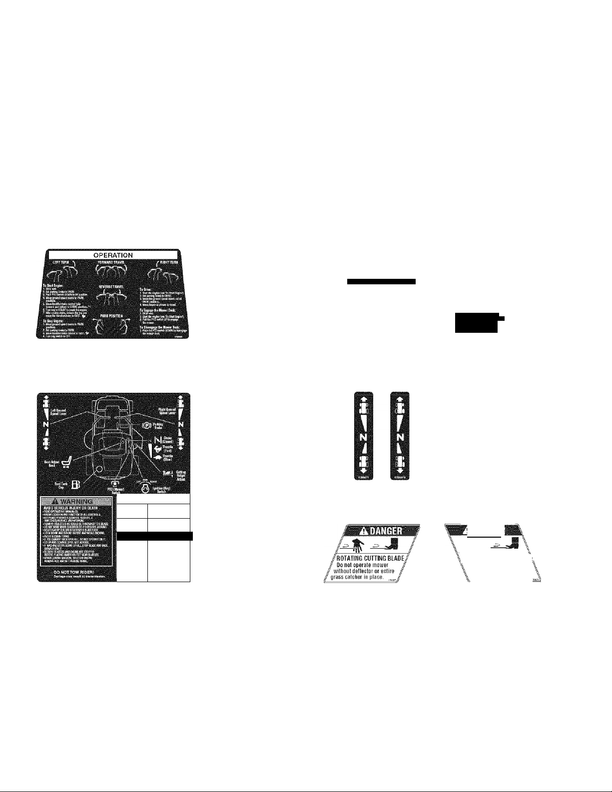
SAFETY & OPERATION DECALS
This unit has been designed and manufactured to pro
vide you with the safety and reliability you would expect
from an industry leader in outdoor power equipment
manufacturing.
Although reading this manual and the safety instructions
it contains will provide you with the necessary basic
knowledge to operate this equipment safely and effec
tively, we have placed several safety labels on the unit to
remind you of this important information while you are
operating your unit.
Decal - Ignition
Switch
Part No. 1726526
Decal - Operation, Upper
Part No. 1726429
All DANGER, WARNING, CAUTION and instructional
messages on your rider and mower should be carefully
read and obeyed. Personal bodily injury can result when
these instructions are not followed. The information is for
your safety and it is important! The safety decals below
are on your rider and mower.
If any of these decals are lost or damaged, replace them
at once. Contact a Sears Parts & Service Center for
replacements.
These labels are easily applied and will act as a constant
visual reminder to you, and others who may use the
equipment, to follow the safety instructions necessary for
safe, effective operation.
DO NOT OPEN RESERVOIRS!
LattWhael . .
Decal - Sealed
Hydraulic System
Part No. 1726525
'('pg'SHPwItmft Shewn) . -
' Controls Located -
' ' Beneath Hitch' '
Decal -Transmission
Release Valve
Part No. 1726834
ROTATING BLADES CUT
OFF ARMS AND LEGS
STOfN««
CHIIOSEK ÄßE HEAß
ik DANGER 1
QPERATIRGOM SLOPES
GAR BE OAMGEROUS.
tEtePERArOfi'SMAALIAL
AHILL 60 HOtDmVE ANA
EkONATOFERATE SNSlOßES
Decal - Danger/Warning, Lower
Part No. 1726430
Decal - Cutting
Height Adjustment
Part No. 1721197
Decal - Parking
Brake
Part No. 1726529
Decal - Danger,
Rotating Blades
Part No. 1704277
Decal - Ground Speed
Control - LH/RH
Part No. 1725671 / 1725670
mm
ROTATING CUTTING BLADE\
Oo not put hands
under mower
blade is
Decal - Danger,
Rotating Blades
Part No. 1704276
detk while
rotating.
or teet
Page 7
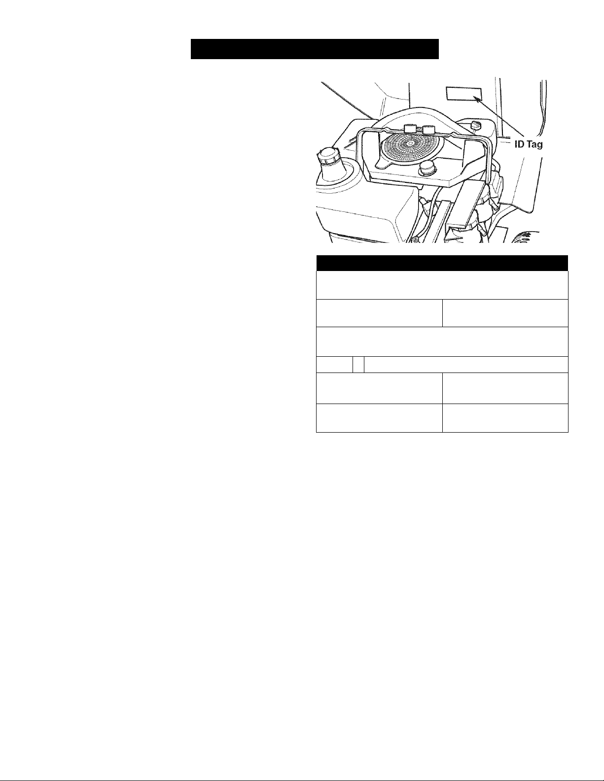
IDENTIFICATION NUMBERS
For Paris & Service
CRR$^rinN
Model No.:
' vv vv vv
I234I
Sears, Roebuck and Co.
3333 Beverly Road
Hoffman Esiate.s, IL 60179
When contacting the service center for replacement
parts, service, or information you MUST have these
numbers.
Record your model name/number, manufacturer’s identi
fication numbers, and engine serial numbers in the
space provided for easy access.
The identification tag is located on the underside of the
seat deck. Tilt the seat deck forward to access the ID
tag.
For answers to your questions about this product, call:
1-800-659-5917
Sears Craftsman Help Line, 5 am - 5 pm,
Monday-Saturday.
Call 1-SOO-4MY-HOME
www.sears.com
|¡!¡¡II!I!¡II¡¡
l!!!ll!l!lll!l
PRODUCT REFERENCE DATA
Model Description Name/Number
Stock Number Unit Serial Number
Date Purchased
.
................................................................................................................\
Engine Make
Engine Type/Spec Engine Code/Serial Number
El igiric'; Mcv:|;;í|
Page 8
’Twin Bag Grass Catcher
’ Headlight Kit
’ Bumper Kit
’ Wheel Weights
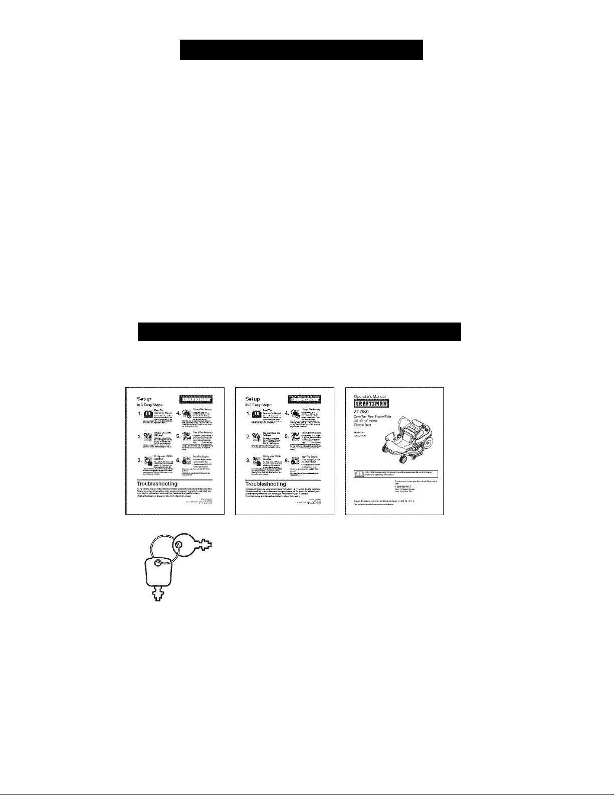
LITERATURE PACKAGE CONTENTS
OPTIONAL ACCESSORIES
Setup Instructions ■
English
Keys
Setup Instructions ■
Spanish
Operator’s Manual & Parts
Book - English/Spanish
Page 9
PRE-OPERATION
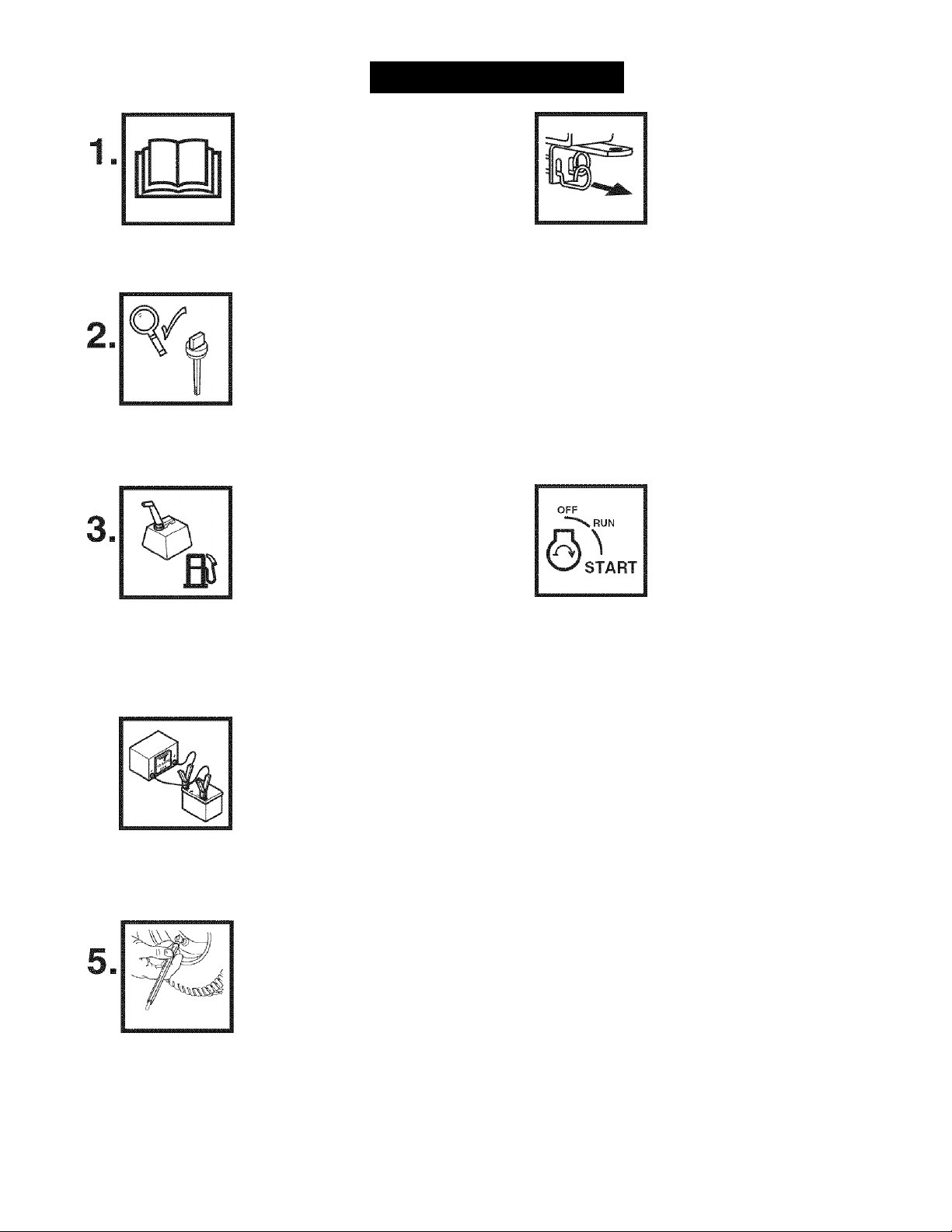
Read The Operator’s Mariual
• Read the operator’s manual.
You should always read and follow
the instructions in the Operator’s
manual. Proper care, performance tips, and safety
information is located in this important document.
Always Check the Oil
Level
• Check the engine oil level.
The engine in your tractor has been
shipped, from the factory, already
filled with 10W-30 weight oil for use during the engine
break-in period. Always check the oil level before
starting the engine.
Fill-Up with FRESH
Gasoline
• Fill the tank with fresh fuel.
The single most common service
issue is stale or contaminated fuel!
Fuel should not be more than 30 days old. Use fuel
stabilizer to extend the life of your fuel, and always
store fuel in an approved, sealed, plastic gas can.
Stale fuel clean-out is not covered under your war
ranty.
Charge The Battery
• Lift the seat deck to access the
battery. If the unit is put into service
after the month and year indicated
on the battery date tag (located on
top of battery) charge the battery for
one hour at 6-10 amps. Refer to the SERVICE &
ADJUSTMENTS section of the operator’s manual for
battery charging information.
Check Tire Pressure
Push Unit Off Crate
To push the unit off the crate:
• Set both transmission release levers
to PUSH position by pulling the levers
back (levers are located under the trail
er hitch).
• Cut the steel banding securing rider to pallet (6 bands).
• Set the parking brake to DRIVE position.
• Set the mower cutting height to its highest setting.
• Fold the cardboard used to crate the unit in half, and
place it under the front wheels of the unit.
• Push the unit forward off the crate.
• Set the transmission release valve levers back to
DRIVE positions (levers pushed in).
Start The Engine
To start the engine:
•While sitting in the operator’s seat, set
the parking brake to PARK. Make sure
the yellow PTO switch is OFF and the
ground speed control levers are locked
in PARK positions.
• Move the engine throttle control fully forward to
CHOKE.
NOTE: A warm engine may not require choking. In this
case, set the throttle control to FAST.
• Insert the key into the ignition switch and turn it to
START.
• After the engine starts, gradually move the throttle con
trol back to FAST position (choke open). Warm the
engine by running it for at least a minute before turning
on the PTO switch, or driving the unit.
• After warming the engine, ALWAYS operate the unit
with the throttle set to FAST position when mowing.
• See the OPERATION section driving information.
• Reduce the tire pressures to the
pressures shown below. Tires are
over-inflated for shipping purposes,
and must be set to the correct pres
sures for optimum traction.
Rear Tire Pressure: 10-12 PS!
Front Tire Pressure: 18-20 PSI
Page 10
OPERATION
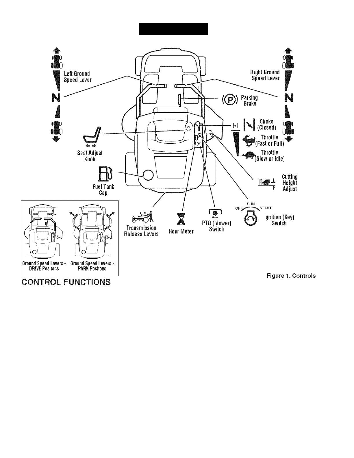
The information below briefly describes the function of individual controls. Starting, stopping, driving, and mowing
require the combined use of several controls applied in specific sequences. To learn what combination and sequence
of controls to use for various tasks please read the entire section.
Ground Speed Levers
These levers control the ground speed of the rider. The
left lever controls the left rear drive wheel and the right
lever controls the right rear drive wheel.
Pushing the levers out, away from the operator’s lap
locks them in PARK positions (inset, Figure 1). Pulling
the levers in across the operator’s lap puts them in
DRIVE positions.
From DRIVE position, moving a lever forward increases
the FORWARD speed of the associated wheel. Pulling
back on a lever increases the REVERSE speed. The fur
ther a lever is pushed, the faster the drive wheel will turn.
See the DRIVING PRACTICE for steering instructions.
The throttle controls engine speed. Always operate at
FULL throttle when mowing. Move the lever forward to
the detent for FULL throttle (FAST). Move the throttle
back to decrease engine speed to IDLE (SLOW).
Close the choke for cold starting. Open the choke once
the engine starts. A warm engine may not require chok
ing. Move the lever forward past the FULL throttle detent
to close the choke. Move the lever back to the detent to
open the choke.
Throttle Control
Choke
10
Page 11

Mower Height of Cut Adjustment
To adjust cutting height, rotate the turn crank clockwise
to raise the mower deck and counterclockwise to lower
the mower deck.
Ignition Switch
The ignition switch starts and stops the engine; it has
three positions:
OFF Stops the engine and shuts off the
electrical system.
RUN Allows the engine to run and powers the
electrical system.
START Cranks the engine for starting.
NOTE: Never leave the ignition switch in the RUN posi
tion with the engine stopped. This drains the battery.
Hour Meter
The hour meter measures the number of hours the key
has been in the RUN position. The hour meter will flash
an oil change indicator at 5 hours, and a lubrication
reminder every 50 hours. These reminders will automati
cally reset themselves.
NOTE: The hour meter wiii register the passage of time
when the key is in the RUN position, even if the engine is
not running.
PTO Switch
The PTO (Power Take-Off) switch engages and disen
gages an electric clutch attached to the engine crank
shaft. This electric clutch drives and stops the mower
deck. To turn the mower on, pull the switch UP. Push the
switch DOWN to turn the mower off. Note that the opera
tor must be seated firmly in the rider seat for the PTO to
function.
Transmission Release Levers
The transmission release levers deactivate the transmis
sions so that the unit can be pushed by hand. See
PUSHING THE UNIT BY HAND for operational informa
tion.
I Seat Adjustment Knob
The seat can be adjusted forward and backward. Tip the
seat forward, loosen the adjustment knob, slide the seat
to the desired position, and tighten the knob.
Fuel Tank
To remove the cap, turn counterclockwise.
Parking Brake
DRIVE Releases the parking brake.
PARK Locks the parking brake.
GENERAL OPERATING SAFETY
Before first time operation:
• Be sure to read all information in the Safety and
Operation sections before attempting to operate this
rider and mower.
• Become familiar with all of the controls and how to stop
the unit.
• Drive in an open area without mowing to become accus
tomed to driving the unit.
Pull the parking brake lever up to engage the parking
brake (PARK position). Move the lever fully down to dis
engage the parking brake (DRIVE position).
NOTE: To start the unit the parking brake must be in
PARK position.
Awarning
If you do not understand how a specific control
functions, or have not yet thoroughly read the
CONTROL FUNCTIONS section, do so now.
Do NOT attempt to operate the rider without first
becoming familiar with the location and function
of ALL controls.
11
Page 12
CHECKS BEFORE STARTING
• Check that the crankcase oil is filled to full mark on
dipstick.
• Adjust the seat position and make certain you can
reach all controls.
• Fill the fuel tank with fresh fuel.
FUEL RECOMMENDATIONS
For daily operation: Use only unleaded gasoline with a
pump sticker octane rating of 87 or higher. Gasohol (up
to 10% ethyl alcohol, 90% unleaded gasoline by volume)
is approved as a fuel. Methyl Teriary Butyl Ether (MTBE)
and unleaded gasoline blends (up to a maximum of 15%
MTBE by volume) are approved as a fuel. No other gasoline/alcohol or gasoline/ether blends are approved. Do
not use fuel additives other than fuel stabilizer.
For storage: CAUTION: Alcohol blended fuels (called
gasohol or using ethanol or methanol) can attract mois
ture which leads to separation and formation of acids
during storage. Acidic gas can damage the fuel system
of an engine while in storage.
To avoid engine problems, the fuel system should be
emptied before storage of 30 days or longer. Drain the
gas tank, start the engine, and let it run until the fuel
lines and carburetor are empty (see STORAGE for fuel
draining procedure). Use fresh fuel next season. See
STORAGE instructions for additional information.
Never use engine or carburetor cleaner products in the
fuel tank or permanent damage may occur. To add fuel:
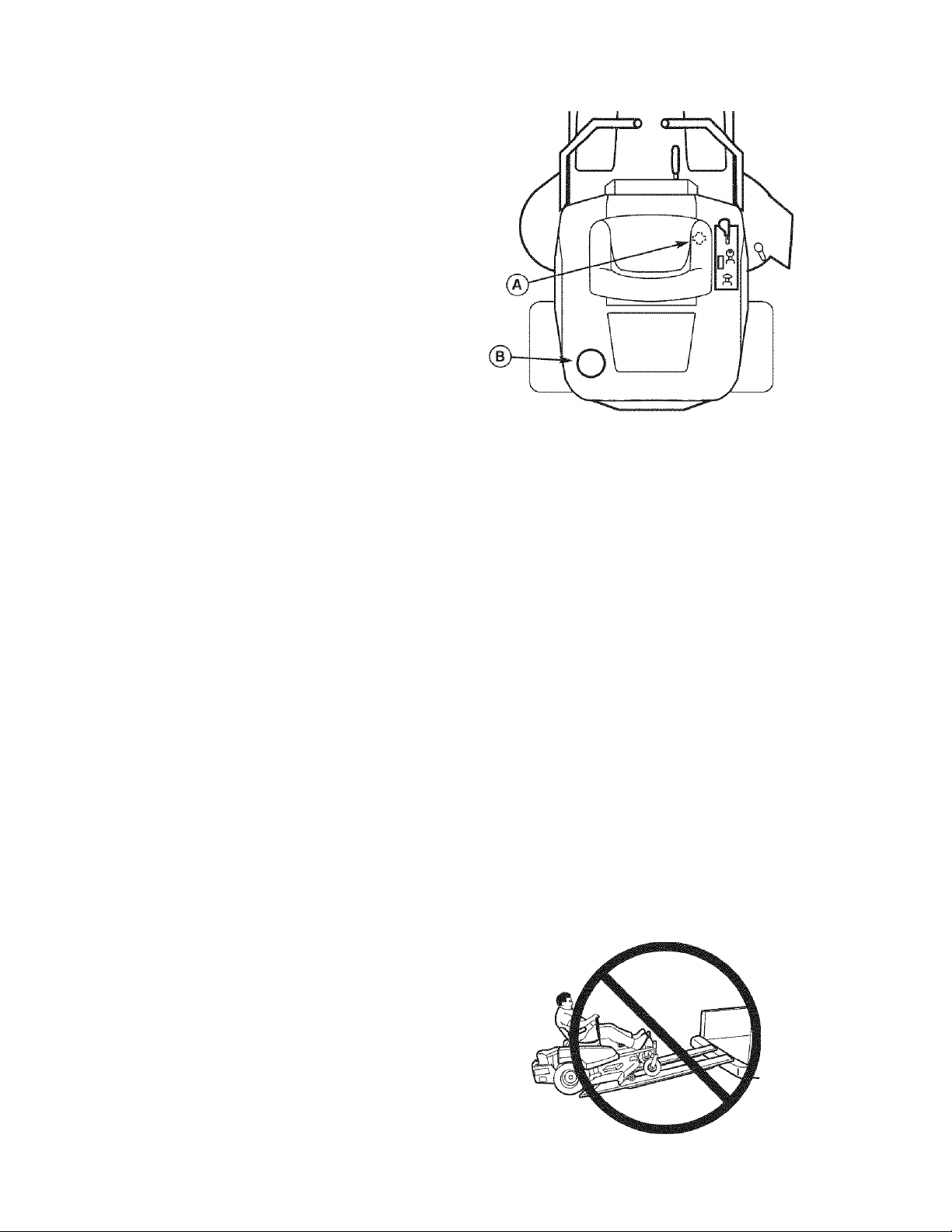
1. Remove the fuel cap (B, Figure 2).
2. Fill the tank. Do not overfill. Leave room in the tank
for fuel expansion.
3. Install and hand tighten the fuel cap.
Awarning
Never allow passengers to ride on the unit.
Before leaving the operator’s position for any
reason, engage the parking brake, disengage the
PTO, stop the engine and remove the key.
To reduce fire hazard, keep the engine, rider and
mower free of grass, leaves and excess grease.
Do not stop or park rider over dry leaves, grass or
combustible materials.
Gasoline is highly flammable and must be
handled with care. Never fill the tank when the
engine is still hot from recent operation. Do not
allow open flame, smoking or matches in the area.
Avoid over-filling and wipe up any spills.
Figure 2. Pre-Start Checks
A. Seat Adjustment Knob
B. Fuel Tank Cap
A WARNING
Never operate on slopes greater than 17.6 percent
(10°) which is a rise of 3-1/2 feet (106 cm)
vertically in 20 feet (607 cm) horizontally.
Select slow ground speed before driving onto a
slope. Use extra caution when operating on
slopes with a rear-mounted grass catcher.
Mow UP and DOWN the slope, never across the
face. Use caution when changing directions and
DO NOT START OR STOP ON A SLOPE.
A WARNING - TRAILERS
Do not load this zero-turn rider on a trailer or
truck using two separate ramps. Only use a
single ramp that is at least one foot wider than
the width of the rear wheels of this rider. This
rider has a zero turning radius and the wheels
could fall off the ramps, or the rider could tip over
injuring the operator or bystanders.
12
Page 13
EMERGENCY STOPPING
In the event of an emergency the engine can be stopped
by simply turning the ignition switch to STOP. Use this
method only in emergency situations. For normal engine
shut down follow the procedure given in STOPPING THE
RIDER AND ENGINE.
8. Begin mowing. See DRIVING PRACTICE.
9. When finished, turn the PTO switch OFF.
10. Stop the engine (see STOPPING THE RIDER AND
ENGINE).
PUSHING THE RIDER BY HAND
STOPPING THE RIDER & ENGINE
1. Returning the ground speed control levers to PARK
positions will stop rider movement.
2. Stop the mower by pushing down on the PTO switch.
3. Move the parking brake lever to PARK position.
4. Move the throttle control to FAST position and turn
the ignition key to OFF. Remove the key.
STARTING THE ENGINE
1. While sitting in the operator’s seat, set the parking
brake to PARK. Make sure the PTO switch is OFF
and the ground speed control levers are locked in
PARK positions.
2. Move the engine throttle control fully forward to
CHOKE.
NOTE: A warm engine may not require choking. In this
case, set the throttle control to FAST.
3. Insert the key into the ignition switch and turn it to
START.
4. After the engine starts, gradually move the throttle
control back to FAST position (choke open). Warm
the engine by running it tor at least a minute before
turning on the PTO switch, or driving the unit.
5. After warming the engine, ALWAYS operate the
unit with the throttle set to FAST position when
mowing.
1. Turn the PTO switch OFF, set the parking brake to
PARK, turn the ignition switch OFF, remove the key,
and wait for all moving parts to stop.
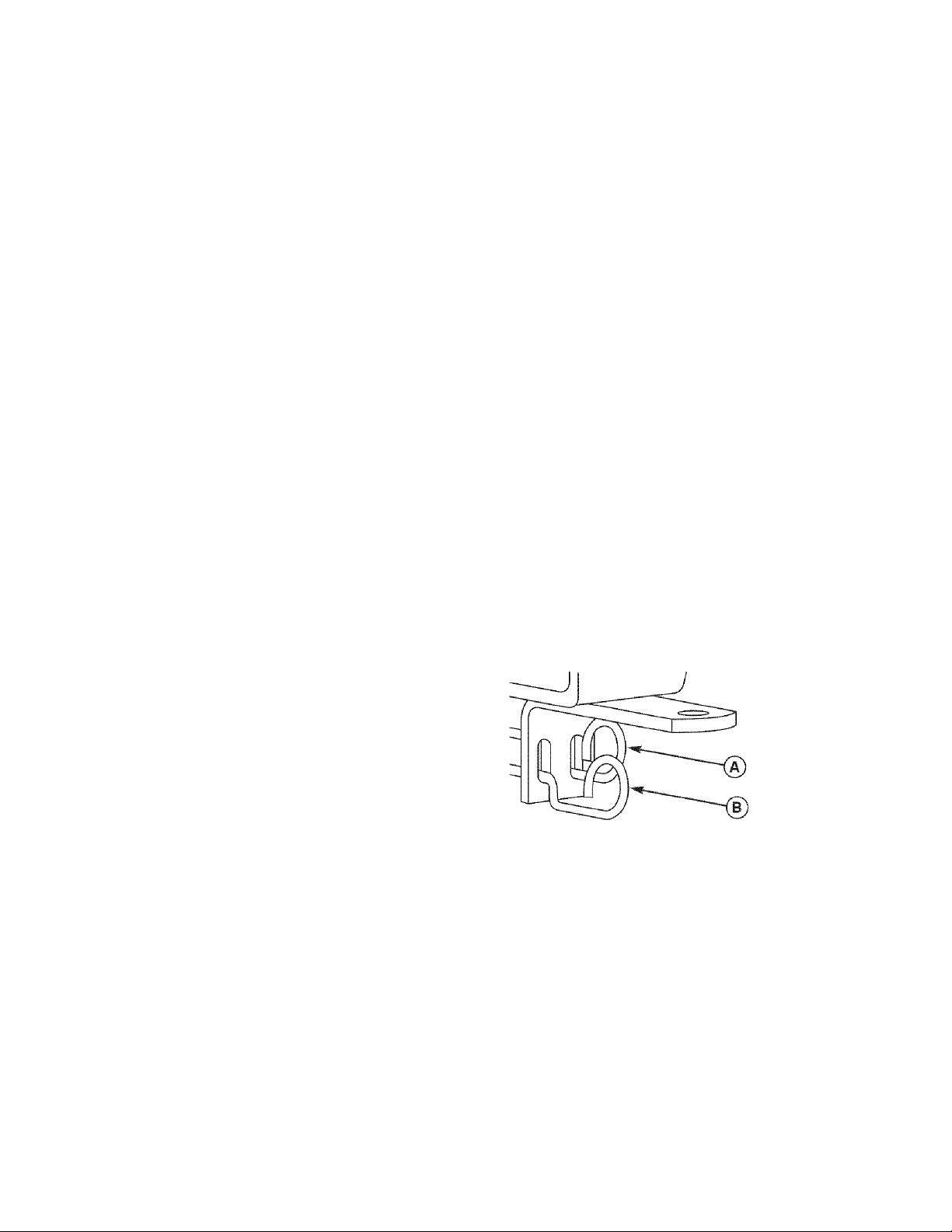
2. Locate the transmission release levers (A & B, Figure
3) at the rear of the unit.
3. Pull both levers back and down to release the trans
missions (position B, Figure 3).
4. Set the parking brake to DRIVE.
The rider can now be pushed by hand.
5. After moving the rider, set the parking brake to PARK
and move the transmission release levers up and in
to re-engage the transmissions (position A, Figure 3).
DO NOT TOW RIDER
Towing the unit will cause transmission dam
0
age. Do not use another vehicle to push or
pull this unit.
MOWING
1. Place the parking brake lever in PARK position. Make
sure the PTO switch is OFF, the ground speed control
levers are locked in their PARK positions, and the
operator is in the seat.
2. Set the mower cutting height to the desired setting.
3. Start the engine (see STARTING THE ENGINE).
4. Set the throttle to FAST.
5. Turn the PTO switch ON to engage the mower deck.
6. Move the parking brake lever to DRIVE position.
7. Move the ground speed control levers from PARK
positions to drive positions (levers in across the oper
ator’s lap).
Figure 3. Transmission Release Levers
A. Drive Position
B. Push Position
13
Page 14
DRIVING PRACTICE -
BASIC DRIVING
WARNING: Never operate on slopes greater than 17.6%
(10°). See SLOPE OPERATION in the safety section.
Zero turn riders operate differently from other four
wheeled vehicles. The drive wheels are also your steer
ing wheels. If you cannot drive the unit on a hill, you will
not be able to steer the unit on it. Operating zero turn
units on slopes requires extra caution.
The lever controls of the zero turn rider are very respon
sive, and learning to gain a smooth and efficient control
of the rider’s forward, reverse, and turning movements
will take some practice.
Spend some time going through the following maneuvers
and becoming familiar with how the unit accelerates,
travels, and steers — before you begin mowing —is
absolutely essential to getting the most out of the zero
turn rider.
Locate a smooth, flat area of your lawn — one with
plenty of room to maneuver. (Clear the area of objects,
people and animals before you begin.) Operate the unit
at mid-throttle during this practice session (ALWAYS
operate at full throttle when mowing), and turn slowly to
prevent tire slippage and damage to your lawn.
Smooth Travel
The lever controls of the
zero turn rider are
highly responsive.
The BEST method of
handling the ground
speed control levers is in
three steps — as shown
in Figure 4.
FIRST place your hands
onto the levers as
shown.
SECOND, to go forward
gradually push the levers
forward with your palms.
THIRD, to speed up
move the levers farther
forward. To slow down
smoothly, slowly move
the levers back toward
neutral.
Figure 4. Move Control
Levers Gradually
We suggest you begin with the Smooth Travel procedure
to the right, and then advance through the forward,
reverse, and turning maneuvers.
You must set the parking brake to DRIVE prior to moving
the control levers out of park position.
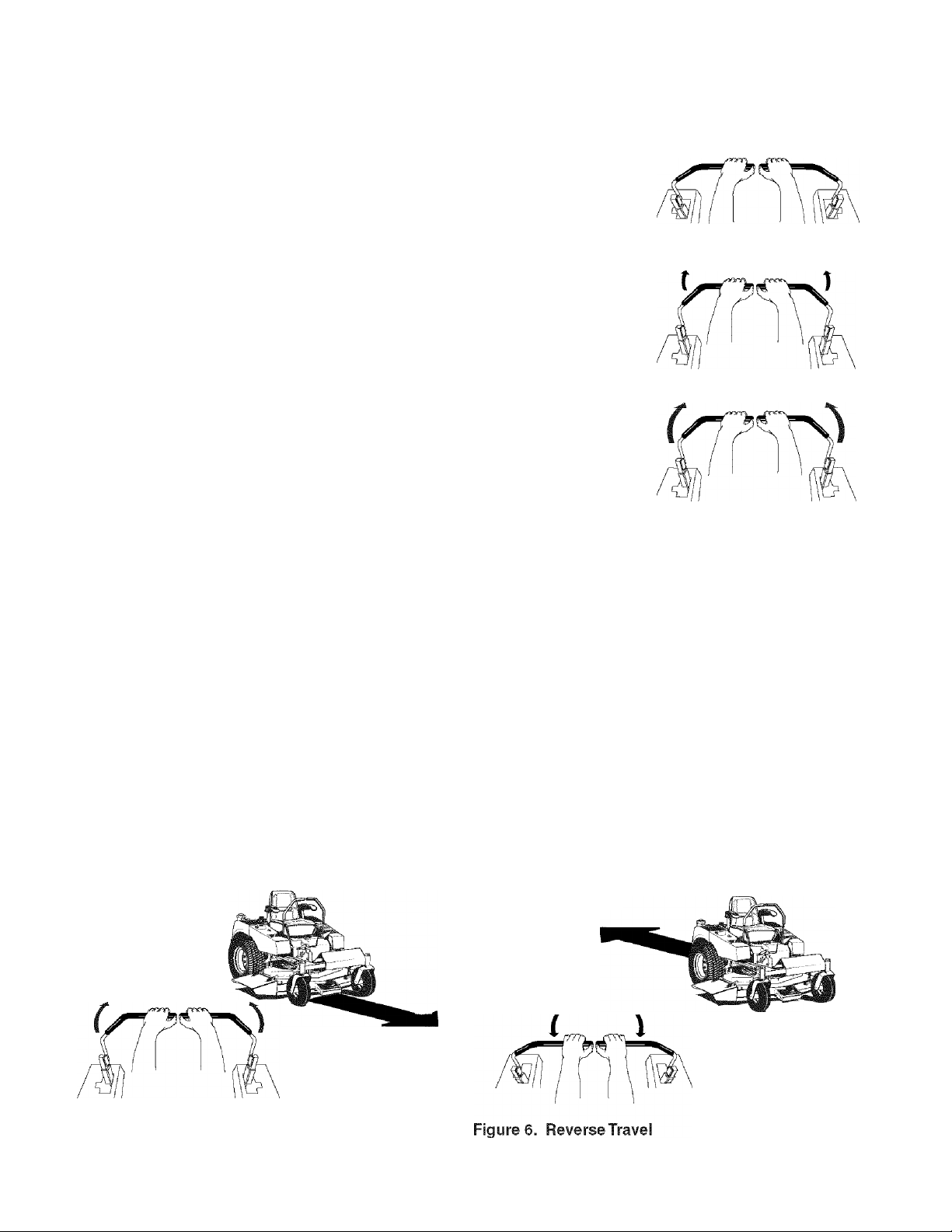
A WARNING
Do not mow in reverse unless absolutely
necessary. Always look down and behind before
and while travelling in reverse.
Forward Travel
Forward Travel Practice
Gradually move both ground speed control levers evenly
FORWARD from neutral. Slow down and repeat.
Reverse Travel Practice
LOOK DOWN & BEHIND, then gradually move both
ground speed control levers evenly BACK from neutral.
Slow down and repeat.
NOTE: Practice backing up for several minutes before
attempting to do so near objects. The rider turns as
sharply in reverse as when going forward, and backing
up straight takes practice.
Reverse Travel
Figure 5. Forward Travel
14
Page 15
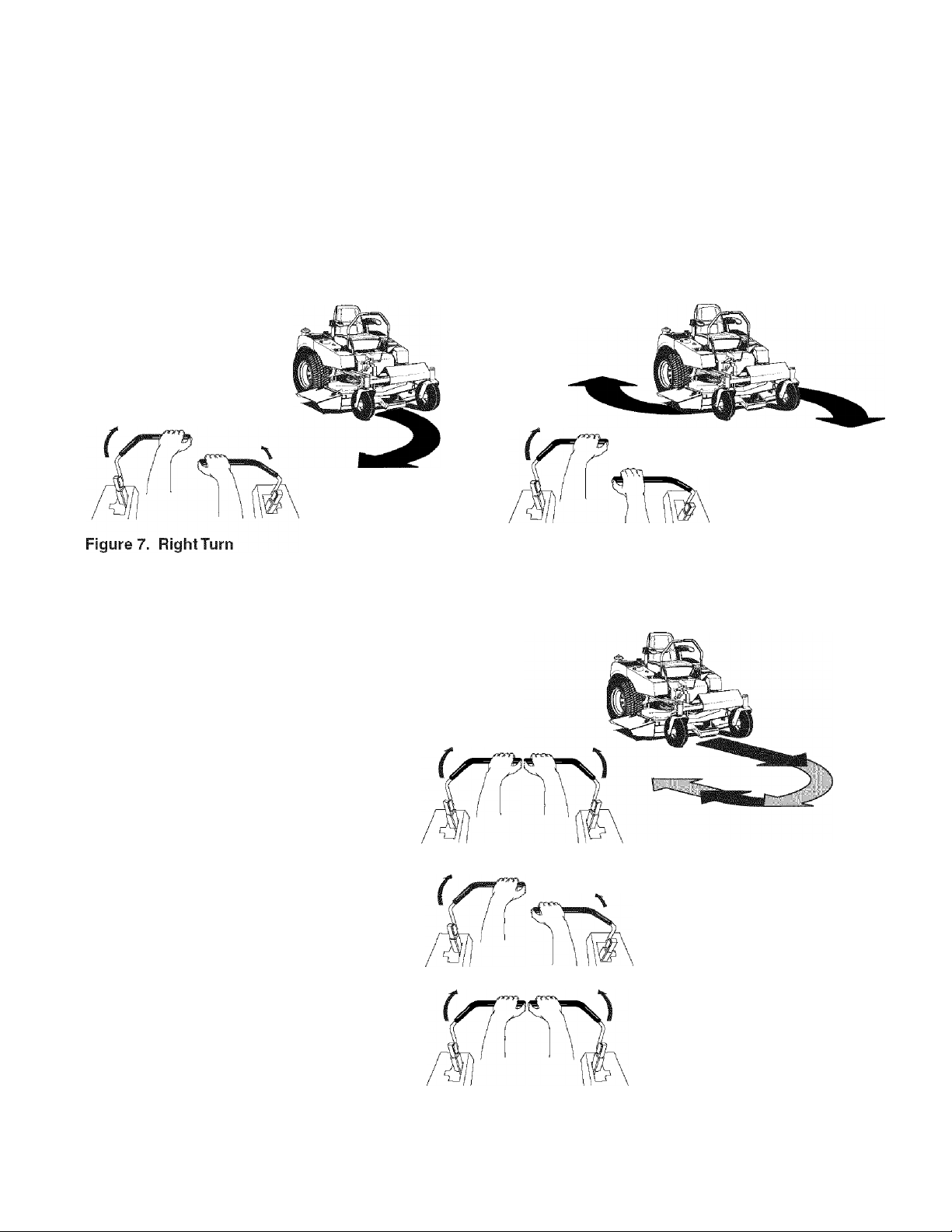
Practice Turning Around a Corner
Practice Turning In Place
While traveling forward allow one handle to gradually
return back toward neutral. Practice several times before
mowing.
NOTE: To prevent pivoting directly on the tire tread, it is
best to keep both wheels going at least slightly forward.
Executing Turns
ADVANCED DRIVING
To “zero turn” means to turn in place. To turn in place,
gradually move one ground speed control lever forward
from neutral and one lever back from neutral simultane
ously. Repeat several times.
Turning In Place
l
Figure 8. Turning in Place
Executing an End-Of-Row Zero
Turn
Your zero turn rider’s unique ability to turn in
place allows you to turn around at the end of
a cutting row rather than having to stop and
make a Y-turn before starting a new row.
For example, to execute a right end-of row
zero turn:
1. Slow down at the end of the row.
2. Move the LEFT ground speed control
lever forward slightly while moving the
RIGHT ground speed control lever back to
center and then slightly back from center.
3. Begin mowing forward again.
This technique turns the rider RIGHT and
slightly overlaps the row just cut —eliminating
the need to back up and re-cut missed grass.
>4s you become more familiar and experi
enced with operating the zero turn rider, you
will learn more maneuvers that will make your
mowing time easier and more enjoyable.
Remember, the more you practice, the bet
ter your controi of the rider will be!
Figure 9. Executing an End-Of-RowTurn
15
Page 16
MOWER DECK REMOVAL & INSTALLATION
NOTE: Perform mower removal and installation on a
hard, level surface such as a concrete floor.
A WARNING
Engage parking brake, disengage PTO, stop
engine and remove key before attempting to
install or remove the mower.
Removing the Mower Deck
1. Turn the PTO off, set the parking brake to PARK, turn
the ignition OFF, remove the key, and wait for ali mov
ing parts to stop.
2. Pivot the rider’s front wheels forward.
3. Place the cutting height adjustment crank (D, Figure
f 0) in the lowest cutting position.
4. Release tension on the drive belt using the mower
belt release lever (E, Figure 10) and remove the drive
belt from the engine pulley.
5. Disconnect the front hitch by removing the hitch rod
and clip (A, Figures 10 & 11), and lifting the mower
hitch (B) up and off the rider hitch bracket (D).
6. Slide the mower deck forward until the rear mower
supports (C) disengage the frame of the rider.
7. Slide the mower deck out from under the right side of
the rider.
Installing the Mower Deck
1. Pivot the rider’s front wheels forward.
2. Place the cutting height adjustment crank (D, Figure 10)
in the lowest cutting position.
3. Slide the mower deck under the right side of the rider.
Slide the mower backwards making sure that the rear
mower supports (C, Figure 11) slide up the ramps on
the frame. The rear of the mower is supported by
these frame ramps.
Hang the mower hitch (B, Figure 11) on the rider
4.
hitch bracket (D) and secure with the hitch rod and
clip (A).
Use the mower belt release lever (E, Figure 12) to
5.
release tension on the mower idler pulley, and install
the drive belt as shown In Figure 12.
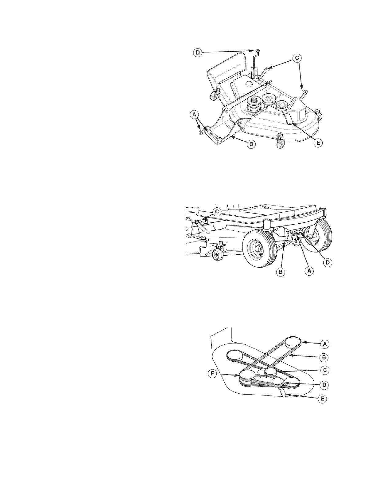
Figure 10. Mower Components
A. Hitch Rod and Clip
B. Mower Hitch
C. Rear Mower Supports
D. Cutting Height Adjustment Crank
E. Mower Belt Release Lever
Figure 11. Mower Hitch Components
A. Hitch Rod and Clip
B. Mower Hitch
C. Rear Mower Supports
D. Rider Hitch Bracket
Figure 12. Mower Belt Routing
A. Engine Pulley
B. Mower Drive Belt
C. Back-Side Idler Pulley
D. V-ldler Pulley
E. Mower Belt Release Lever
F. Mower Drive Pulley
16
Page 17

MAINTENANCE
MAINTENANCE SCHEDULE
The following schedule should be followed for normal care of your rider and mower. You will need to keep a record of
your operating time. Determining operating time is easily accomplished by observing the elapsed time recorded by
the hour meter.
RIDER MAINTENANCE
ITEMS
Clean Debris from Rider and Engine
Compartment *
Clean Debris from Engine Cooling Areas
& Air Filter *
Check Tire Pressure
Lubricate Rider & Mower *
Clean Deck & Check/Replace Mower
Blades
Clean Battery & Cables
Check Rider Safety System **
Check / Adjust PTC Clutch
ENGINE MAINTENANCE ITEMS
Check Engine Oil Level
Service Air Filter Pre-Cleaner *
Replace Air Filter *
Change Engine Oil *
Replace Spark Plug
Replace Fuel Filter
Change Engine Oil & Filter *
Before
Each Use
#
•
Every Spring
&Falf
• •
m •
8
Hours25Hours
e
•
•
•
100
Hours
•
•
200
Hours
e
•
•
•
* More often in hot (over 85“ F: 30“ C) weather or dusty operating conditions.
** Check the function of the safety system after the unit has been stored for 30 days or longer.
17
Page 18
Rider Maintenance Items
CLEAN DEBRIS FROM RIDER AND ENGINE COMPARTMENT
Service interval: Before each use.
CAUTION: If debris is not removed from the engine
compartment and other hot surfaces, it creates a fire
hazard. Before starting the unit at the beginning of the
mowing session, remove any grass clippings, dirt,
leaves, or other debris from the unit. Also clean out the
engine compartment.
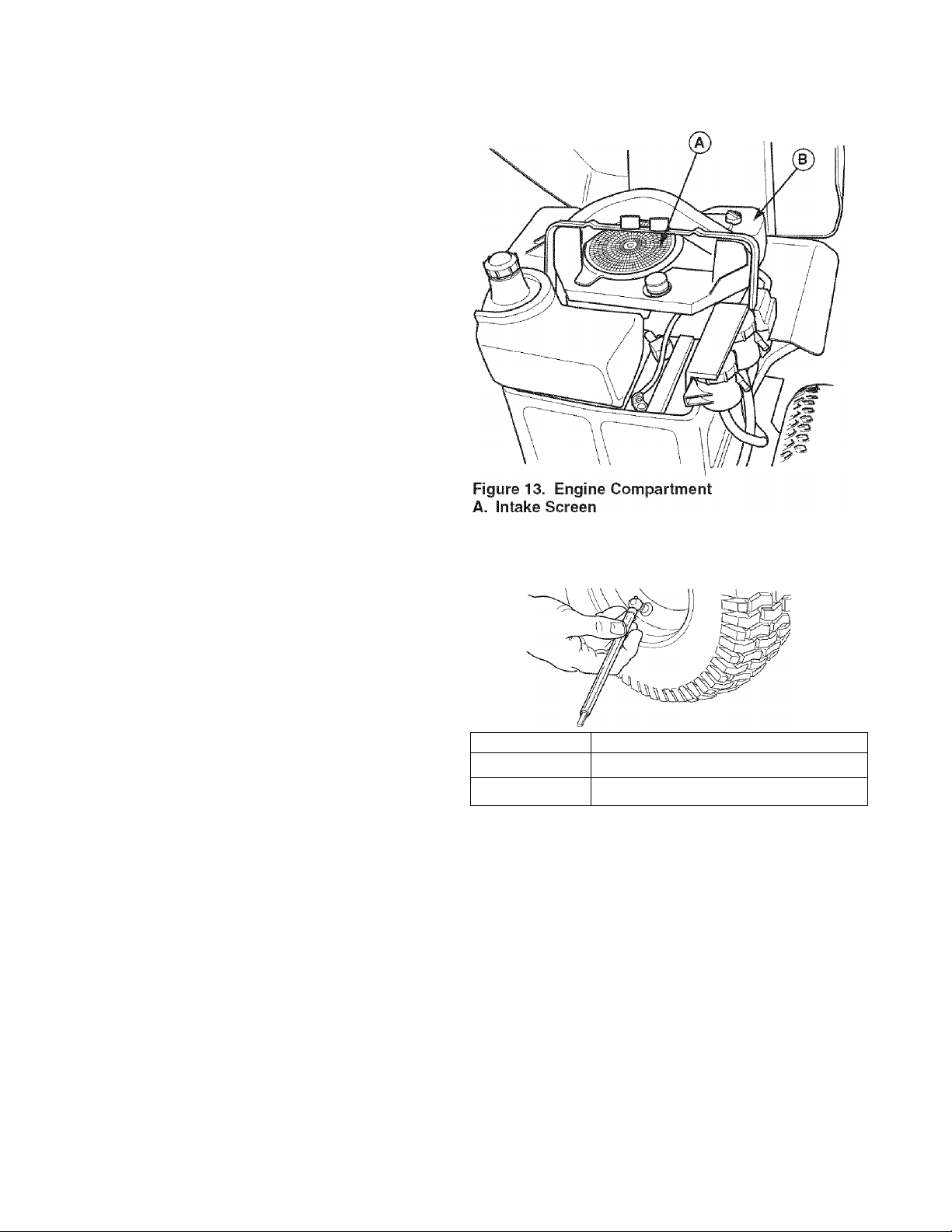
CLEAN DEBRIS FROM ENGINE COOLING AREAS AND AIR FILTER
Service Interval: Before each use.
CAUTION: If debris is not removed from the engine
compartment and other hot surfaces, it creates a fire
hazard. Before starting the unit at the beginning of the
mowing session, lift the seat deck and clean any debris
from the intake screen on top of the engine (A, Figure
13), exposed engine cooling fins, and around the air filter
assembly. Also open the air filter cover (B) and remove
any debris that has accumulated in the air filter compart
ment.
B. Air Filter Cover
CHECKTIRE PRESSURE
Service Interval: 25 Hours.
Tire pressure should be checked periodically, and main
tained at the levels shown in Figure 14. Note that these
pressures may differ slightly from the “Max Inflation”
stamped on the side-wall of the tires. The pressures
shown provide proper traction, improve cut quality, and
extend tire life.
Tire Pressure
Front 18-20 psi (1,24-1,38 bar)
Rear 10-12 psi (,69-,83 bar)
Figure 14. Tire Pressures
18
Page 19
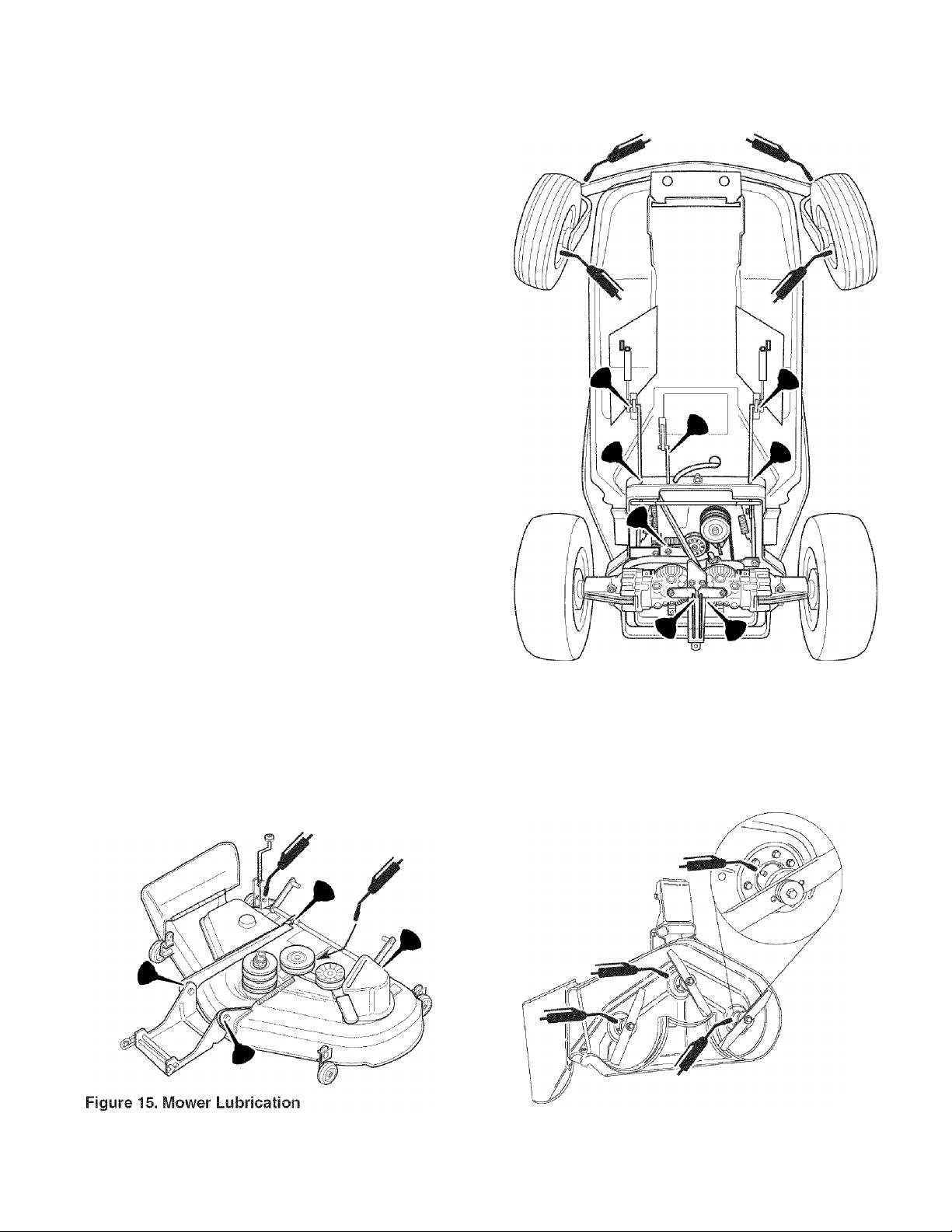
LUBRICATION
Service Interval: 25 hours.
Lubricate the unit at the locations shown in Figures 15
through 17 as well as the following lubrication points.
Grease:
front wheel grease fittings
■ front wheel bushings
■ mower pivots
■ mower arbors
i
Use grease fittings when present.
Not all greases are compatible. Use automotive-type lithi
um grease.
Oil:
■ rear frame assembly pivot
■ hydro linkage
i
■ seat adjustment assembly
■ brake linkage
■ frame pivot points
■ mower deck height adjustment linkage
Generally, all moving metal parts should be oiled where
contact is made with other parts. Keep oil and grease off
belts and pulleys. Remember to wipe fittings and sur
faces clean both before and after lubrication.
Figure 16. Lubricating Rider
Figure 17. Arbor Lubrication
19
Page 20
CLEAN DECK &
CHECK ! REPLACE MOWER BLADES
Service Interval: 25 hours or as required.
A WARNING
For your personal safety, do not handle the sharp
mower blades with bare hands. Careless or
improper handling of blades may result in serious
injury.
----------------------
A WARNING
For your personal safety, blade mounting
capscrews must each be installed with a
hex/spline washer and spring washer, then
securely tightened. Torque blade mounting
capscrew to 45 - 55 ft. lbs. (61 - 75 N.m.)
1. Remove mower deck (see “Mower Deck Removal” in
the OPERATION section).
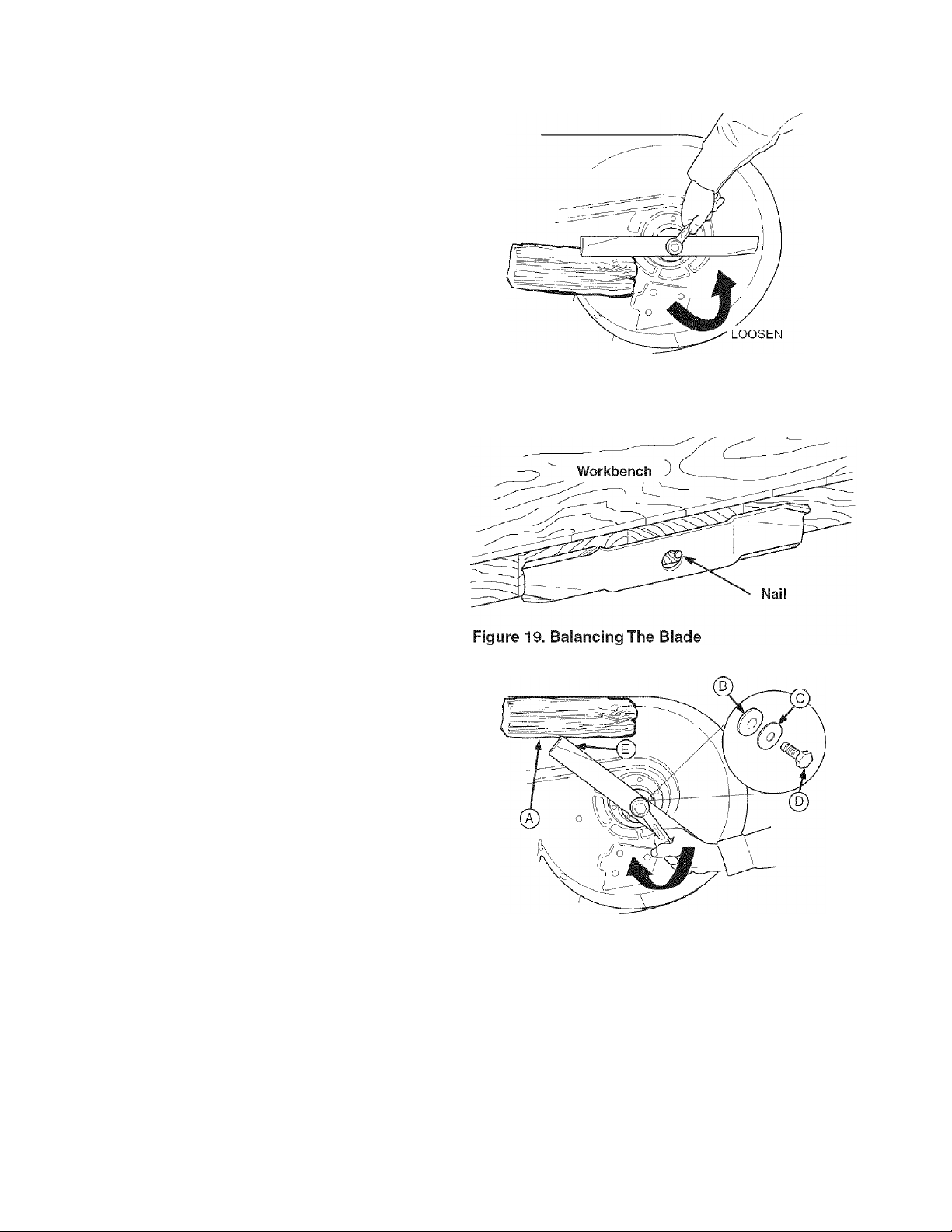
2. See Figure 18. Remove blade to inspect it or to safe
ly access the underside of the mower deck. Use a
block of wood to prevent blade rotation while loosen
ing the capscrew by turning it counterclockwise.
3. Remove the capscrew (D, Figure 20), spring washer
(C) , hex washer (B), and blade.
4. Clean the underside of the mower deck.
5. Inspect the blades for nicks or dull edges. Use a file
to sharpen blade to a fine edge. If the blade is dam
aged, it must be replaced.
6. Balance the blade as shown in Figure 19. Center the
blade’s hole on a nail lubricated with a drop of oil. A
balanced blade will remain level. If the blade is not
balanced, continue to sharpen the heavy side until it
balances.
7. Reinstall the blade with the lift wings (E, Figure 20)
pointing up toward the mower deck as shown.
8. Reinstall the hex washer (B, Figure 20), spring wash
er (C) and capscrew (D). Use a wooden block (A) to
prevent blade rotation while tightening the capscrew
(D) to 45-55 ft. lbs. (61-75 N.m). Turn capscrew
clockwise to tighten.
Figure 18. Blade Removal
Figure 20. Blade Installation
A. 4x4 Wood Block
B. Hex Washer
C. Spring Washer
D. Blade Capscrew
E. Lift Wings
20
Page 21
CLEANING THE BATTERY AND CABLES
^WARNING
Be careful when handling the battery. Avoid
spilling electrolyte. Keep flames and sparks away
from the battery.
When removing or instaliing battery cables,
disconnect the negative cable FIRST and reconnect
it LAST. If not done in this order, the positive
terminal can be shorted to the frame by a tool.
Always wear safety glasses and gloves when
handling batteries.
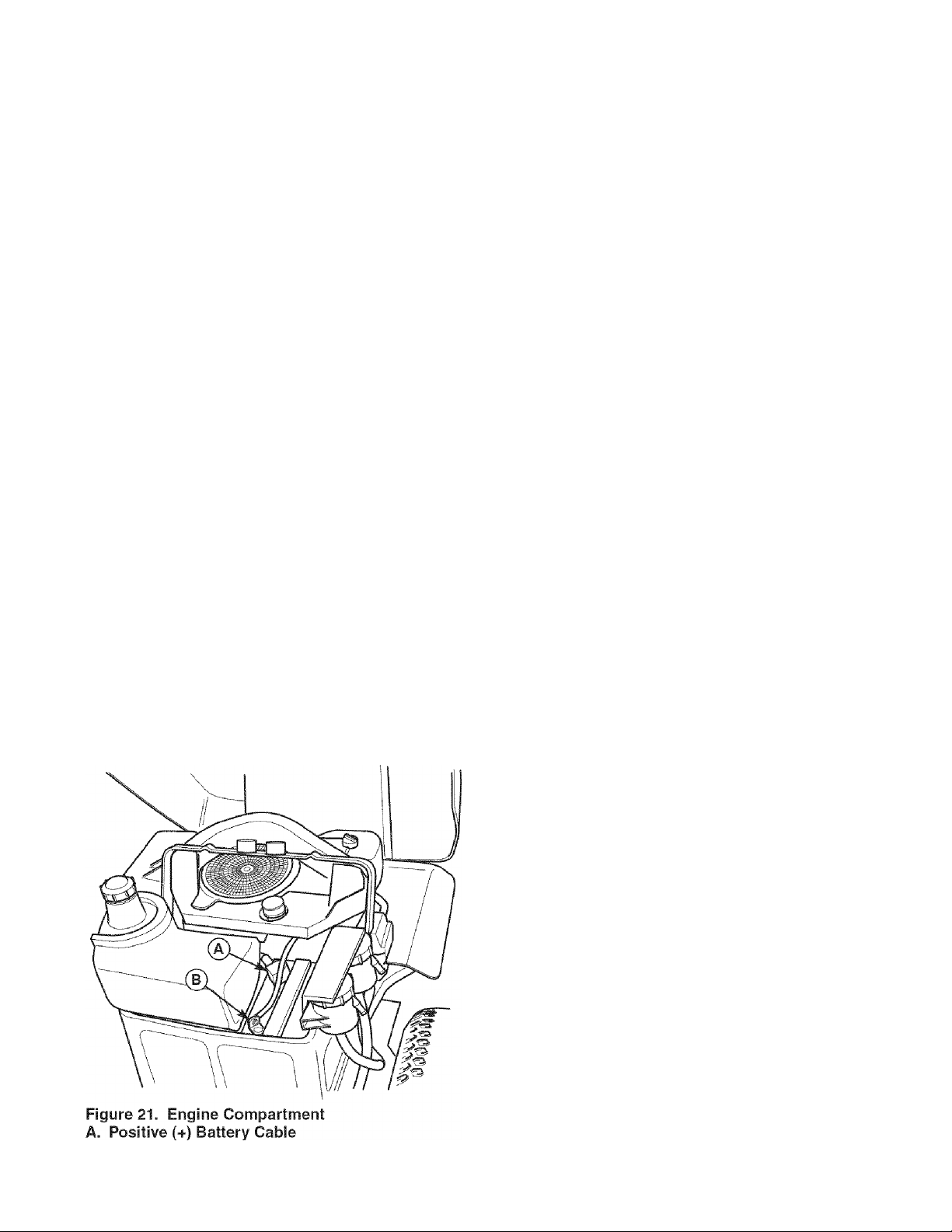
Service Interval: 200 Hours
1. Disconnect the cables from the battery, negative
cable first (B, Figure 21).
2. Remove the rubber strap securing the battery, and
remove the battery.
3. Clean the battery and battery compartment with a
solution of baking soda and water.
4. Clean the battery terminals and cable ends with a
wire brush until shiny.
5. Reinstall the battery and secure with the rubber strap.
6. Reattach the battery cables: first attach the positive
cable (see A, Figure 21), then attach the negative
cable (B).
7. Coat the cable ends and battery terminals with petro
leum jelly or non-conducting grease.
CHECK RIDER SAFETY
A
Service interval: 200 Hours & Every Spring/Fall
This unit is equipped with safety interlock switches.
These safety systems are present for your safety. Do
not attempt to bypass safety switches, and never tamp
er with safety devices. Check their operation regularly.
Operational SAFETY Checks
TEST 1 — ENGINE SHOULD NOT CRANK IF:
• PTO switch is ON, OR
• Parking brake is in DRIVE position, OR
• Ground speed control levers are not in their PARK
positions.
TEST 2 — ENGINE SHOULD CRANK IF:
• PTO switch is OFF, AND
• Parking brake is in PARK position, AND
• Ground speed control levers are locked in their
PARK positions.
TEST 3 — ENGINE SHOULD SHUT OFF IF:
• Operator rises off seat with the PTO ON, OR
• Operator rises off seat with the parking brake in
DRIVE position, OR
• Operator moves the ground speed control levers
out of their PARK positions before setting the park
ing brake to DRIVE.
TEST 4 — BLADE BRAKE CHECK
The mower blades and mower drive belt should come
to a complete stop within five seconds after the PTO
switch is turned OFF. If mower drive belt does not stop
within five seconds, contact a Sears Parts & Repair
Center.
SYSTEM
B. Negative (-) Battery Cable
NOTE: Once the engine has stopped, the PTO switch
must be turned OFF, parking brake must be set to
PARK, and the ground speed control levers must be
locked in their PARK positions in order to start the
engine.
A WARNING
If the unit does not pass a safety test, do not
operate it. See a Sears Parts & Repair Center.
Under no circumstance should you attempt to
defeat the purpose of the safety interlock
system.
21
Page 22
CHECK / ADJUST PTO CLUTCH
A WARNING
To avoid serious injury, perform adjustments oniy
with engine stopped, key removed and tractor on
level ground.
Service Interval: 200 Hours.
The PTO clutch is engaged and disengaged by the PTO
switch. The clutch powers and brakes the mower blades.
Check the PTO clutch adjustment every 200 hours of
operation. Also perform the following procedure if the
clutch is slipping, will not engage, or if a new clutch has
been installed.
1. Remove key from ignition switch and disconnect
spark plug wires to prevent the possibility of acciden
tal starting while the PTO is being adjusted.
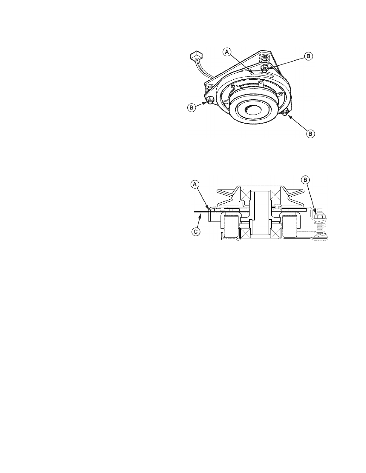
2. See Figure 22. Note the position of the 3 adjustment
windows (A) in the side of the brake plate and the
nylock adjustment nuts (B).
3. Insert a .012”-.015” (2,5-4mm) feeler gauge (0)
through each window, positioning the gauge between
the rotor face and the armature face as shown in
Figure 23.
4. Alternately tighten the adjustment nuts (B, Figure 22)
until the rotor face and armature face just contacts
the gauge.
5. Check the windows for an equal amount of tension
when the gauge is inserted and removed, and make
any necessary adjustments by tightening or loosen
ing the adjustment nuts.
NOTE: The actual air gap between the rotor and arma
ture may vary even after performing the adjustment pro
cedure. This is due to dimensional variations on compo
nent parts, and is an acceptable condition.
6. Check the mower blade stopping time. The mower
blades and mower drive belt should come to a com
plete stop within five seconds after the electric PTO
switch is turned off. If adjustment does not stop a
mower braking problem, replace the electric PTO
clutch.
----------------
Figure 22. PTO Clutch Adjustment
A. Adjustment Window (Qty. 3, one shown)
B. Adjustment Nut
Figure 23. Adjust PTO Clutch
A. Window
B. Adjustment Nut
C. Feeler Gauge
22
Page 23
Engine IVlaintenance items
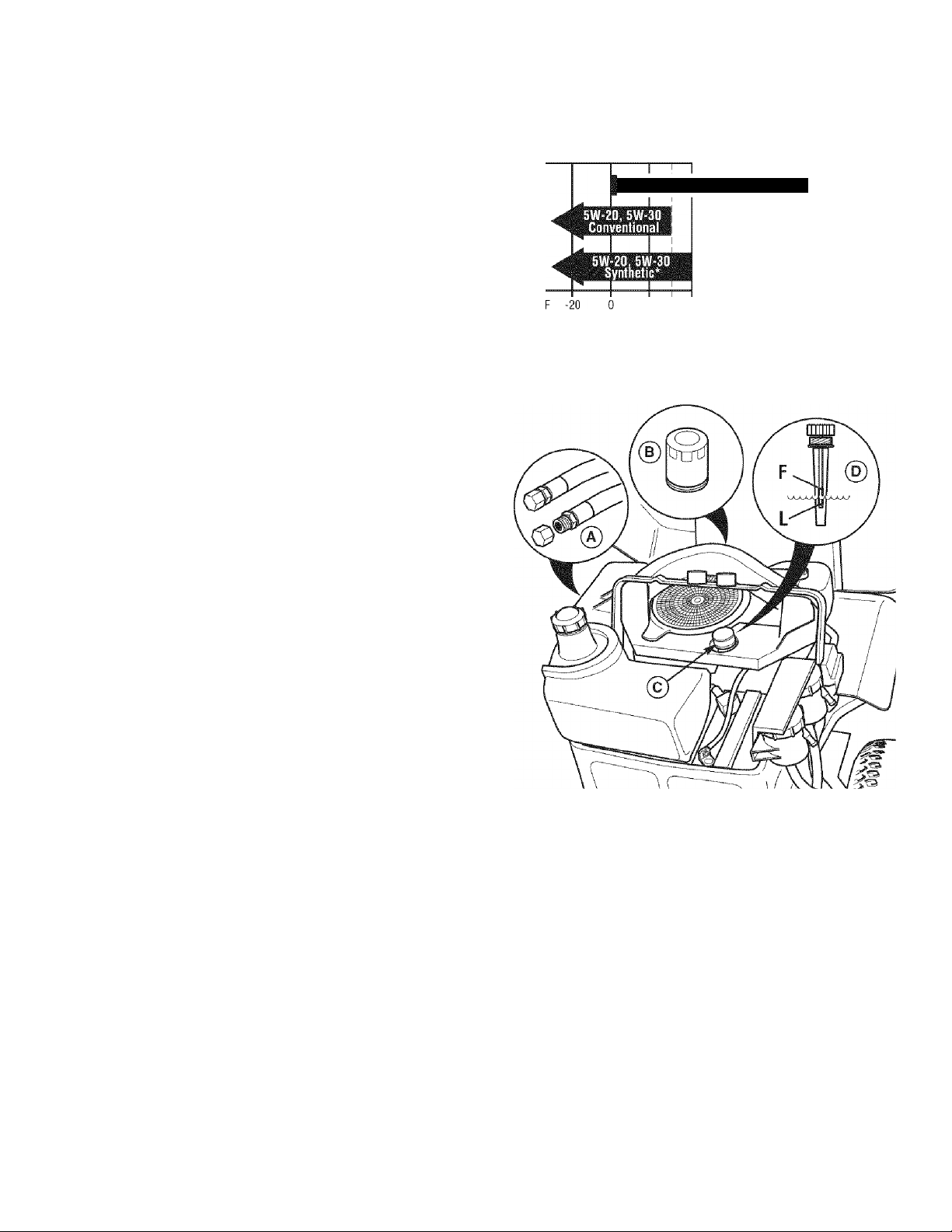
CHECK ENGINE OIL LEVEL
Service Interval: Before each use, and every 8 hours.
1. Turn the engine off, and set the parking brake to
PARK.
2. Clean the area around the dip stick (C, Figure 25).
3. Remove the dip stick (C) and clean it with a paper
towel.
4. Insert the dip stick back into the engine, but do not
thread the cap back onto the tube (D).
5. Remove the dip stick and read the oil level. The oil
level should be between the “F” and “L” marks (D). If
not, add oil according to the oil recommendations
chart (Figure 24).
CHANGE ENGINE OIL
Service Interval: 100 Hours.
Oil Capacity: .95 Quarts with oil filter change.
Note: Change engine oil while the engine is warm. Run
the engine for a few minutes, then shut the engine off
and aliow it to cool from hoi to warm.
1. Clean the area around the dip stick (C, Figure 25)
and oil drain tube (A).
2. Remove the oil drain plug (A) from the end of the oil
drain tube. Remove the dip stick (C). Allow ample
time for complete drainage.
3. Reinstall the oil drain plug (A).
4. Fill the crankcase with oil. See CHECK ENGINE OIL
LEVEL above.
Use oil classified API Service Class SG,
SH,
SJ
or better with SAE Viscosity:
10W-30 Conventional Or Synthetic
20 32 40 60 80
°C -30 -18 -7 0 4 16 27 38
•Recommended: Synthetic oils provide better starting below -10"F.
Figure 24. Recommended Engine Oil
100
CHANGE ENGINE OIL & FILTER
Service interval: 200 Hours.
Oil Capacity: .95 Quarts with oil filter change.
Note: Change engine oil while the engine is warm. Run
the engine for a few minutes, then shut the engine off
and aliow it to cool from hoi to warm.
1. Clean the area around the dip stick (C, Figure 25)
and oil drain (A).
2. Remove the oil drain plug (A) and and dip stick (C).
Allow ample time for complete drainage.
3. Remove the oil filter (B). Discard the filter.
4. Turn the new filter upside down and fill with fresh
engine oil. Allow the oil to seep into the new filter for
two minutes.
5. Using a drop of oil on your finger tip, wet the rubber
gasket on the bottom of the new filter.
Figure 25. Oil Change
A. Oil Drain Tube
B. Oil Filter
C. Dip Stick
D. Checking Oil Level
6. Dump the oil out of the filter and install the filter on
the filter base. Turn the filter clockwise until the rub
ber gasket meets the filter base. Then turn 2/3 to 1
full turn more.
7. Reinstall the oil drain plug (A).
8. Fill the crankcase with oil. See CHECK ENGINE OIL
LEVEL above.
9. Test run the engine to check for leaks. Stop the
engine for 1 minute, then recheck the oil level.
23
Page 24
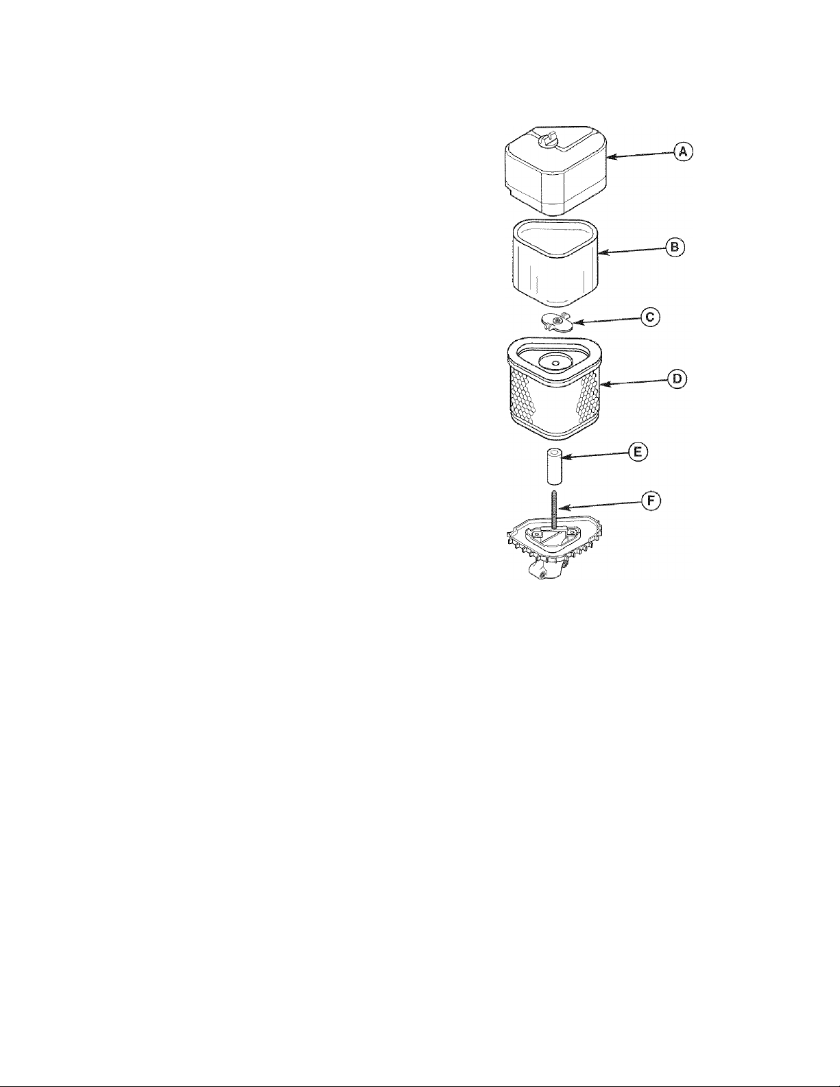
SERVICE AIR FILTER PRE-CLEANER
Service interval: 25 Hours or as required.
1. Loosen the air filter cover knob and remove the cover
(A, Figure 26). Clean out any debris from around the
air filter. Inspect the condition of the sealing surfaces
of the air filter element (D) and filter base. Replace
any damaged parts.
2. Remove the foam pre-cleaner (B) from the air filter
element (D).
3. Wash the pre-cleaner (B) with warm water and deter
gent. Rinse thoroughly. Squeeze out all excess
water. DO NOT wring out. Allow the pre-cleaner to air
dry.
4. Saturate the pre-cleaner with new engine oil.
Squeeze out the excess oil. DO NOT wring out.
Squeeze the pre-cleaner in a paper towel until all
excess oil has been removed.
5. Reinstall the pre-cleaner (B) over the air filter (D).
6. Reinstall the air cleaner cover (A).
REPLACE AIR FILTER
Service Interval: 100 Hours or as required.
1. Loosen the air filter cover knob and remove the cover
(A, Figure 26). Clean out any debris from around the
air filter. Inspect the condition of the sealing surfaces
of the air filter (D) and filter base. Replace any dam
aged parts.
2. Remove the foam pre-cleaner (B) from the air filter
element. Service the pre-cleaner as described in
SERVICE AIR FILTER PRE-CLEANER above.
3. Remove the wing nut (C). Remove and replace the
air filter (D).
4. Reinstall the wingnut (C) and pre-cleaner (B).
5. Reinstall the air cleaner cover (A).
Figure 26. Air Filter Assembly
A. Air Filter Cover & Knob
B. Foam Pre-Cleaner
C. Wingnut with Locking Material
D. Air Filter
E. Rubber Seal
F. Stud
24
Page 25
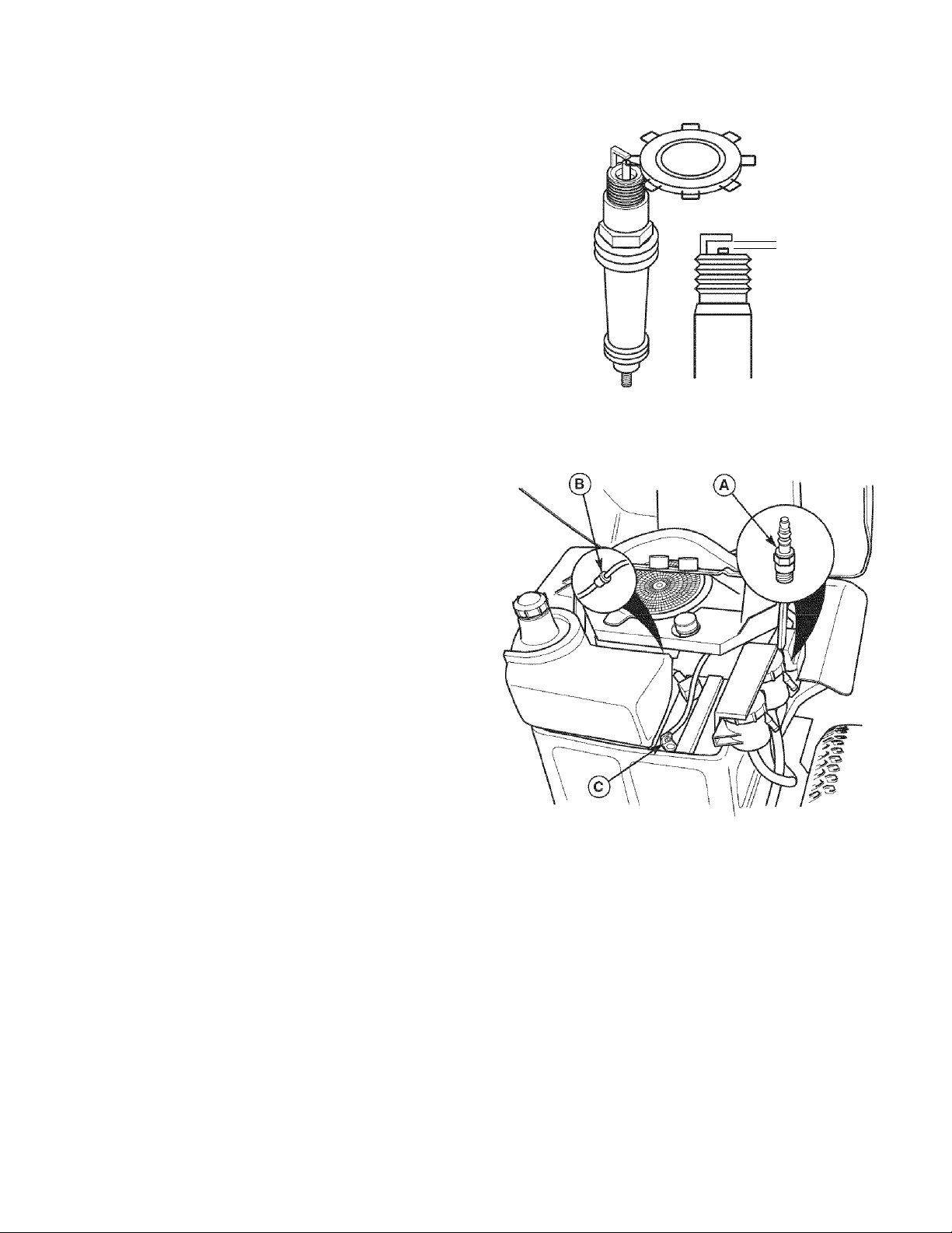
REPLACE SPARK PLUG
Service Interval: 200 Hours.
Replacement Spark Plug: Champion RC12YC or equiv
alent
Spark Plug Gap: .040” (1mm)
1. Stop the engine and allow it to cool.
2. Clean the area around the spark plug (A, Figure 28).
3. Remove the spark plug and inspect it. If at all dam
aged or worn, replace it.
4. Check the spark plug gap. The gap (new or used
plug) should be .040” (see Figure 27).
5. Reinstall the plug into the cylinder head (Figure 28).
Torque the plug to 28-32 ft. lbs. (38-43 N.m.).
REPLACE FUEL FILTER
.040"
Figure 27. Spark Plug Gapping
A WARNING
Gasoline is highly flammable and must be
handled with care. Never fill the tank when the
engine is still hot from recent operation. Do not
allow open flame, smoking or matches in the area.
Avoid over-filling and wipe up any spills.
Do not remove fuel filter when engine is hot, as
spilled gasoline may ignite. DO NOT spread hose
clamps further than necessary. Ensure clamps
grip hoses firmly over filter after installation.
Service interval: 200 Hours.
The fuel filter is located in the fuel line between fuel tank
and carburetor. If the filter is dirty or clogged, replace as
follows:
1. Stop the engine and allow the unit to cool .
2. Disconnect the negative battery cable from the nega
tive battery terminal (C, Figure 28).
3. Using locking pliers, clamp off the fuel line on both
sides of the fuel filter (B).
4. Place a suitable container under the fuel filter to
catch spilled fuel.
5. Spread the fuel filter clamps only far enough to
remove the clamps. Move the clamps away from the
fuel filter.
6. Remove and replace the fuel filter.
7. Secure the fuel filter with the original clamps and
remove the locking pliers.
8. Reconnect the negative battery cable (C) when fin
ished.
--------
Figure 28. Engine Compartment
A. Spark Plug
B. Fuel Filter
C. Negative Battery Terminal & Cable
25
Page 26
SERVICE & ADJUSTMENTS
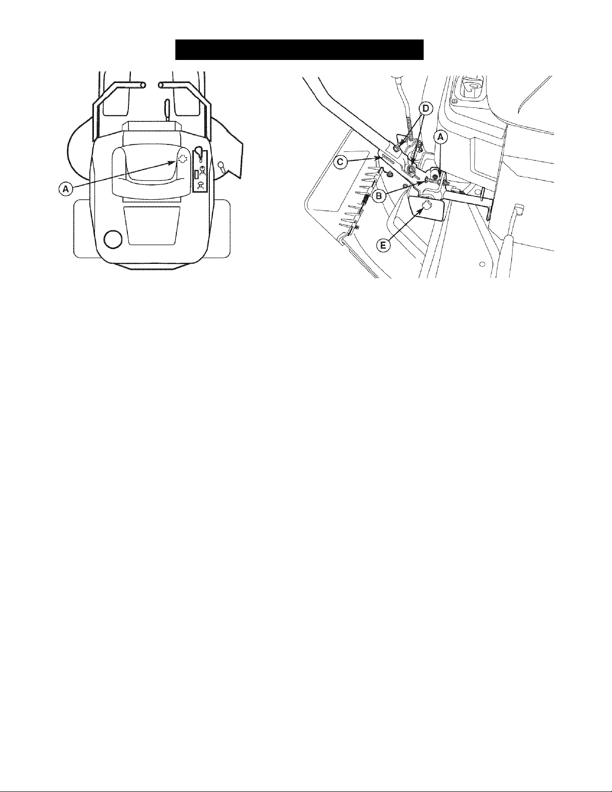
Figure 29. Seat Adjustment
A. Seat Adjustment Knob (Underside of Seat Deck)
SEAT ADJUSTMENTS
The seat and ground speed control levers should be
adjusted so the ground speed control levers can be
moved through their full range of motion.
Figure 30. Control Lever Adjustment
A. Jam Nut
B. Carriage Bolt
C. Forward Slot
D. Mount Bolts
E. Knob
The seat can be adjusted forward and back. Loosen the
adjustment knob (A, Figure 29) located on the underside
of the seat deck, move the seat to the desired position,
then tighten the knob.
GROUND SPEED CONTROL LEVER ADJUSTMENT
The control levers have three adjustments:
To Adjust Control Lever Height: Pull the levers in
across the operator’s lap to their DRIVE positions.
Loosen the mount bolts (D, Figure 30) and raise or lower
the levers to the desired position. Tighten the mounting
bolts.(D).
To Adjust Control Lever End Gap: The control lever
end gap should be adjusted so that the levers do not
contact each other when placed in DRIVE positions.
Loosen the jam nut (A, Figure 30) and adjust the length
of the carriage bolt (B) so that the levers do not contact
each other. Repeat on the opposite side. Tighten the
jam nut (A) to lock the carriage bolt in position.
To Adjust Operator Clearance: The space between the
operator and the control levers can be increase by
removing the upper mounting bolt (D, Figure 30), pivoting
the lever forward, and reinstalling the capscrew through
the control lever and forward slot (C). Repeat with the
other ground speed lever.
SPEED BALANCING ADJUSTMENT
If the rider veers to the right or left when the ground
speed control levers are in the maximum forward posi
tion, the top speed of the right lever can be balanced by
turning the adjustment knob (E, Figure 30). Turn the
knob COUNTERCLOCKWISE to increase speed or
CLOCKWISE to decrease speed
26
Page 27
CUTTING HEIGHT ADJUSTMENT
Turn the cutting height adjustment crank (A, Figure 31)
clockwise to raise the mower deck and counterclockwise
to lower it. If the crank is difficult to turn, thoroughly
clean and lubricate it.
PTO CLUTCH ADJUSTMENT
See CHECK / ADJUST PTO CLUTCH in the
Maintenance Section.
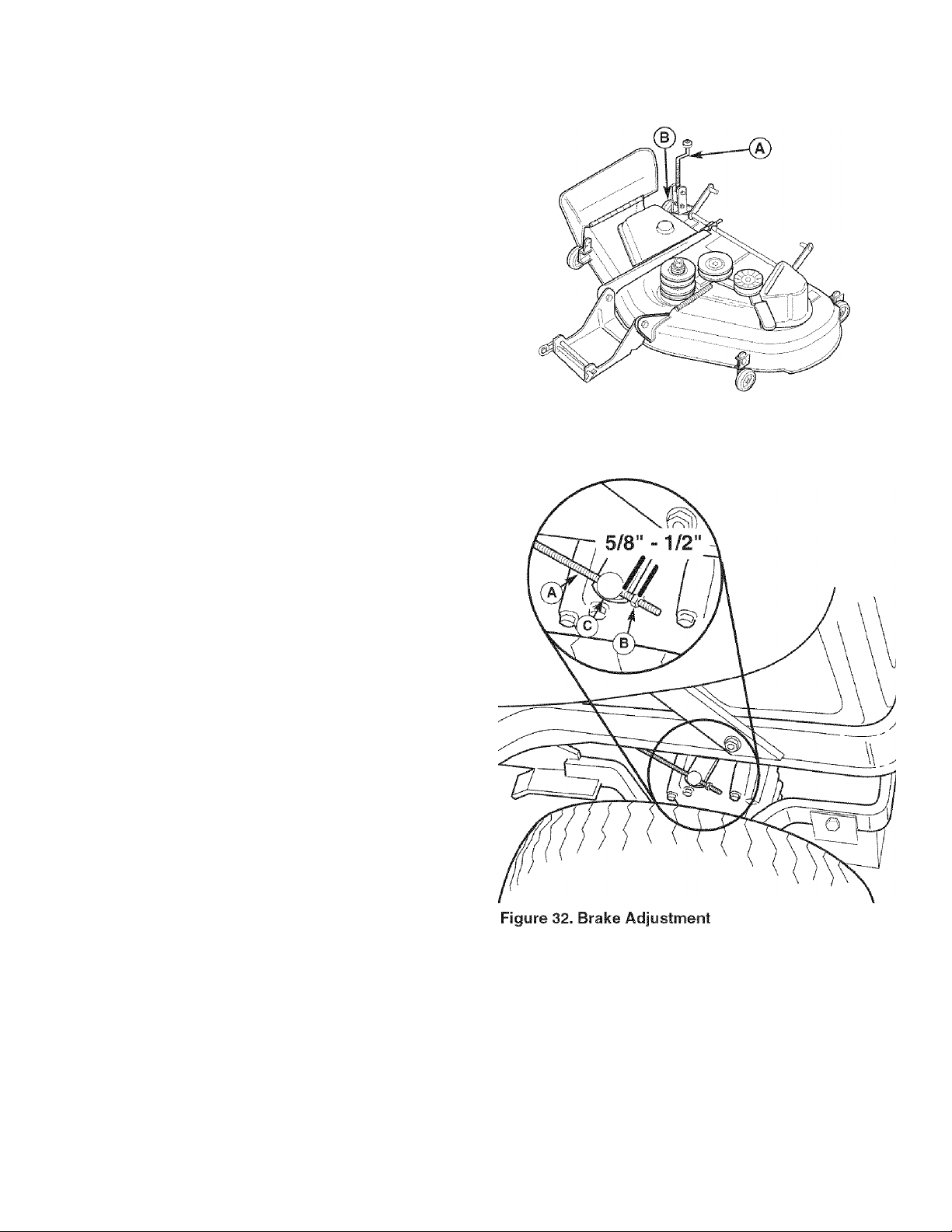
BRAKE ADJUSTMENT
1. Lift up the seat deck.
2. Set the parking brake to DRIVE.
3. Push the brake lever (C, Figure 32) forward and pull
the brake rod (A) back. There should be an approxi
mately 5/8” -1/2” gap between the adjustment nut (B)
and brake lever. If not, adjust the nut (B) until 1/8” is
achieved.
4. Repeat on both sides.
BATTERY CHARGING
Figure 31. Cutting Height Adjustment
A. Cutting Height Adjustment Crank
A WARNING----------------------
Keep open flames and sparks away from the
battery; the gasses coming from it are highly
explosive. Ventilate the battery well during
charging.
A dead battery or one too weak to start the engine may
be the result of a defect in the charging system or other
electrical component. If there is any doubt about the
cause of the problem, contact a Sears Parts & Repair
Center. If you need to replace the battery, follow the
steps under Cleaning the Battery & Cables in the
Regular Maintenance Section.
To charge the battery, follow the instructions provided by
the battery charger manufacturer as well as all warnings
included in the safety rules sections of this book. Charge
the battery until fully charged (until the specific gravity of
the electrolyte is 1.250 or higher and the electrolyte tem
perature is at least 60° F). Do not charge at a rate higher
than 10 amps.
ENGINE ADJUSTMENTS
The carburetor is designed to deliver the correct fuel-toair mixture to the engine under all operating conditions.
The main fuel jet is calibrated at the factory and is not
adjustable. The low idle fuel adjusting needle is also set
at the factory and normally does not need adjustment.
A. Brake Rod
B. Adjustment Nut
C. Brake Lever
To ensure proper operation at altitudes above 5000 feet,
it may be necessary to have an authorized Kohler dealer
install a special high-altitude jet kit in the carburetor. If a
high-altitude kit as been installed, the engine must be
converted back to the original jet size before it is operat
ed at lower altitudes. If not, overheating and engine
damage can result.
27
Page 28
MOWER DECK LEVELING ADJUSTMENTS
A WARNING
Before checking mower, shut off PTO and engine.
Allow all moving parts to stop. Remove ignition
key, then disconnect the spark plug wire and
fasten it away from the spark plug.
If the cut is uneven, the mower may need leveling.
Unequal or improper tire pressure may also cause an
uneven cut. See CHECK TIRE PRESSURE.
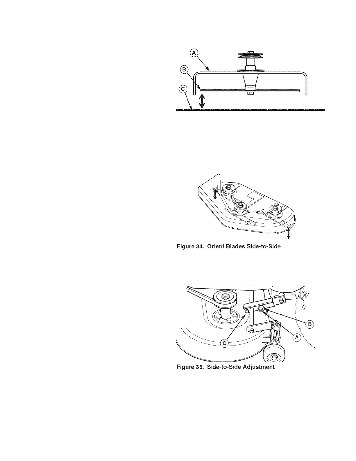
Side to Side Leveling
1. With the mower installed, place the rider on a
smooth, level surface such as a concrete floor. Turn
the front wheels straight forward. Turn the engine off,
set the parking brake to PARK, and wait for all mov
ing parts to stop.
2. Check for bent blades and replace if necessary.
3. Check the tire pressures. See CHECK TIRE PRES
SURE.
4. Set the cutting height to mid position. Arrange the
mower blades so that they are pointing from side-toside (Figure 34).
5. Measure the distance between the tips of the outside
blades and the ground (Figures 33 & 34). If there is
more than 1/8" (3mm) difference between the meas
urements on each side, proceed to step 6. If the dif
ference is 1/8" (3mm) or less, proceed to Front To
Back Leveling.
6. See Figure 35. Loosen the outside nut (A) and taptite
screw (C), then turn the eccentric nut (B) to raise or
lower the left side of the deck. When the mower deck
is level, hold the eccentric nut while tightening the
outside nut. Tighten the taptite screw (C).
Figure 33. Measure Blade Tips to Ground
A. Mower Deck
B. Blade Tip
C. Level Ground
A. Outside Nut
B. Eccentric Nut
C. Taptite Screw
28
Page 29
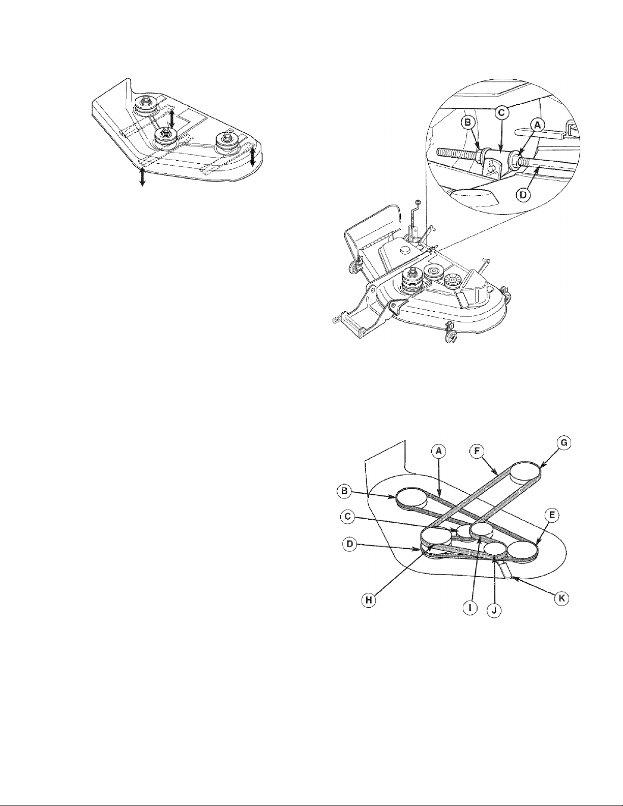
Figure 36. Orient Blades Front-to-Back
Front To Back Leveling
1. Turn the blades front-to-back as shown in Figure 36.
Measure the distance from the ground to front tip of
center blade, and from ground to rear tips of left hand
and right hand blades (Figures 33 & 36). Front tips
should be 1/8"-1/4" (3-6 mm) higher than rear tips. If
not, proceed to step 2.
2. To raise front of mower deck, loosen front nut (A,
Figure 40 inset) and turn rear nut (B) against bracket
(C) to shorten rod (D).
3. To lower the front of mower deck, loosen rear nut (B)
and bracket (C) will move back to lengthen rod (D).
4. Recheck measurement before tightening front nut (A)
against bracket.
MOWER BELT REPLACEMENT
Mower Drive Belt Replacement
1. Park the rider on a level surface. Disengage the PTO,
turn off the engine and set the parking brake.
Remove the key.
2. Use the idler pulley arm (K, Figure 38) to release belt
tension and remove the mower drive belt (F) from the
PTO pulley (G).
3. Remove the belt from the remaining deck pulleys.
Note: It is not necessary to remove the mower deck.
4. Install the new belt (F) as shown in Figure 38.
Figure 37. Front-to-Back Leveling
A. Front Nut
B. Rear Nut
C. Mower Bracket
D. Adjustment Rod
Arbor Drive Belt Replacement
Contact a Sears Parts & Repair Center for replacement
of the arbor drive belt (A, Figure 38).
Figure 38. PTO Belt Routing
A. Arbor Drive Beit
B. Right Arbor Pulley
C. Arbor Idler Pulley
D. Center Arbor Pulley
E. Left Arbor Pulley
F. Mower Drive Beit
G. Engine PTO Pulley
H. Mower Drive Pulley
I. Mower idler Pulley
J. Backside Idler Pulley
K. Idler Pulley Arm
29
Page 30
STORAGE
Before you store your unit for the off-season, read the
Maintenance and Storage instructions in the Safety
Rules section, then perform the following steps:
• Disengage the PTO, set the parking brake, & remove
the key.
• Check all fluid levels. Check all maintenance items.
• Battery life will be increased if it is removed, put in a
cool, dry place and fully charged about once a
month. If the battery is left in the unit, disconnect the
negative cable.
It is important to prevent gum deposits from forming in
the essential fuel system parts such as the carburetor,
fuel filter, fuel line, and fuel tank during storage. Also,
alcohol blended fuels (called gasohol or using ethanol or
methanol) can attract moisture which leads to the sepa
ration and formation of acids during storage. Acidic gas
can damage the fuel system of an engine while in stor
age.
To avoid engine problems, the fuel system should be
emptied before storage of 30 days or longer. Follow
these instructions;
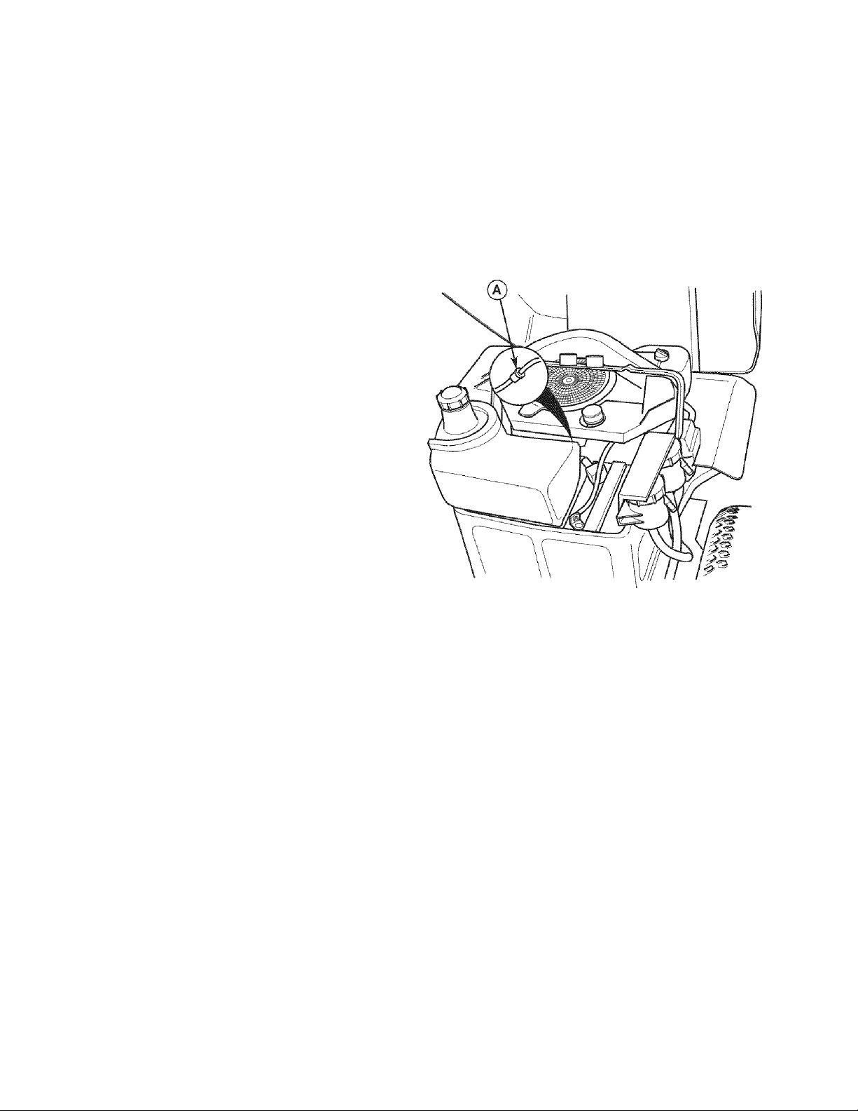
1. Stop the engine, remove the key, and allow the
engine to cool.
2. Place a suitable container below the fuel filter (A,
Figure 39') to catch spilled fuel, and place a contain
er suitable to hold the contents of the fuel tank next to
the unit.
3. Using locking pliers, clamp the fuel line between the
fuel filter (A) and fuel tank.
4. Spread the clamp on the fuel filter only far enough to
slide the clamp away from the filter.
5. Disconnect the fuel line from the fuel filter.
6. Route the fuel line into a suitable container, remove
the locking pliers, and drain the fuel tank.
7. Reconnect the fuel filter, and secure with the clamp.
8. Start and run the unit until all fuel is consumed.
Before starting the unit after it has been stored:
• Check all fluid levels. Check all maintenance items.
» Fill with FRESH fuel.
• After starting, allow the engine to warm before oper
ating.
A WARNING
Never store the unit {with fuel) in an enciosed,
poorly ventilated structure. Fuel vapors can
travel to an ignition source (such as a furnace,
water heater, etc.) and cause an explosion.
Fuel vapor is also toxic to humans and animals.
Figure 39. Engine Compartment
A. Fuel Filter
Awarning
Gasoline is highly flammable and must be
handled with care. Never fill the tank when the
engine is still hot from recent operation. Do not
allow open flame, smoking or matches in the area.
Avoid over-filling and wipe up any spills.
30
Page 31

TROUBLESHOOTING
While normal care and regular maintenance will extend the life
of your equipment, prolonged or constant use may eventually
require that service be performed to allow it to continue operat
ing properly. The troubleshooting guide below lists the most
common problems, their causes and remedies.
If you prefer, all of these procedures can be performed for you
by a Sears Parts & Repair Center. See the back cover for
important Sears Parts & Repair Center information.
Troubleshooting the Rider
PROBLEM CAUSE REMEDY
Engine will
not turnover
or start.
Engine starts
hard or runs
poorly.
Parking brake not set to PARK Set parking brake to PARK.
PTO switch in ON position. Place in OFF position.
Ground speed levers not in PARK positions. Move ground speed levers to PARK positions.
Throttle not in CHOKE position. Move throttle to CHOKE position.
Key not turned fully to START position. Turn key fully to START position.
Out of fuel. If engine is hot, allow it to cool, then refill the fuel
Engine flooded. Move throttle control back to FULL position to open
Gas is old or stale. Drain fuel & replace with fresh fuel. See Storage.
Water in fuel. Drain fuel & refill with fresh fuel. See Storage.
Battery terminals require cleaning. Clean the battery terminals
Battery discharged or dead. Recharge or replace.
Spark plug(s) faulty, fouled or incorrectly
gapped.
Wiring loose or broken. Visually check wiring & replace broken or frayed
Solenoid or starter motor faulty. Replace. Contact Sears Parts & Repair.
Safety interlock switch faulty. Replace. Contact Sears Parts & Service.
Air filter plugged Service pre-cleaner and/or replace air filter ele
Throttle set to CHOKE position longer than
necessary.
Spark plug faulty, fouled, or incorrectly gapped. Clean and gap or replace.
Awarning
To avoid serious injury, perform maintenance on
the rider or mower only when the engine is
stopped and the parking brake set to PARK.
Always remove the ignition key, disconnect the
spark plug wire and fasten it away from the plug
before beginning the maintenance, to prevent
accidental starting of the engine.
tank.
the choke.
Clean and gap or replace.
wires. Tighten loose connections.
ment.
Set throttle to FULL position.
Engine
knocks.
Excessive oil
consumption.
Engine
exhaust is
black.
Low oil level. Check/add oil as required.
Using wrong grade oil. See "Change Engine Cil" in the Maintenance
Section.
Engine running too hot. Clean engine cooling fins, blower screen and air
cleaner.
Using wrong weight oil. See "Change Engine Cil" in the Maintenance
Section.
Too much oil in crankcase. Drain excess oil.
Dirty air filter. Replace air filter. See "Replace Air Filter Element.”
Engine choke control is in closed position. Cpen choke control.
31
Page 32

Engine runs, but
rider will not
drive.
Transmission release levers in PUSH
positions.
Drive belt slips. Clean or replace belt as necessary.
Belt is broken. Replace drive belt. Contact Sears Parts & Repair.
Parking brake is not fully released. Contact Sears Parts & Repair.
Move levers to DRIVE positions.
Rider drive belt
slips.
Parking brake
will not hold.
Rider steers or
handles poorly.
Rider tracks to
one side.
Pulleys or belt greasy or oily. Clean as required.
Belt stretched or worn. Replace belt. Contact Sears Parts & Repair.
Parking brake is incorrectly adjusted. See Service & Adjustments Section.
Improper tire inflation. See Maintenance Section.
Steering linkage is loose. Check and tighten any loose connections.
Ground speed adj. knobs not adjusted. See SPEED BALANCING ADJUSTMENT
Troubleshooting the Mower
PROBLEM CAUSE REMEDY
Mower cutting
height difficult to
adjust.
Mower cut is
uneven.
Mower cut is rough
looking.
Cutting height crank threads dirty or
require lube.
Rider tires not inflated equally or properly. See Maintenance Section.
Mower not leveled properly. See "Mower Leveling" in Service & Adjustments.
Engine speed too slow. Set throttle to FULL when mowing.
Ground speed too fast. Decrease Ground Speed.
Thoroughly clean and lubricate cutting height crank
with oil.
Engine stalls easily
with mower
engaged.
Excessive mower
vibration.
Mower drive belt
slips or fails to
drive.
Blades are dull. Sharpen or replace blades. See Maintenance
Section.
Mower drive belt slipping because it is oily
or worn.
Blades not properly fastened to arbors. See "Check/Replace Mower Blades" in Maintenance
Engine speed too slow. Set to FULL throttle.
Ground speed too fast. Decrease Ground Speed.
Cutting height set too low. Cut tall grass at maximum cutting height during first
Underside of mower deck dirty. Remove mower deck and clean underside.
Discharge chute jamming with cut grass. Cut grass with discharge pointing toward previously
Blade mounting bolts are loose. Tighten to 45-55 ft. lbs. (61 -75 N.m.).
Mower blades, arbors, or pulleys are bent. Check and replace as necessary.
Mower blades are out of balance. Replace or balance blades. See Maintenance
Belt installed incorrectly. Reinstall Correctly.
Idler pulley spring broken or not properly
attached.
Mower drive belt broken. Replace drive belt.
Clean or replace belt as necessary.
Section.
pass.
cut area.
Section.
Repair or replace as needed.
PTO clutch out of adjustment. Adjust PTO clutch. See Maintenance Section.
32
Page 33

Manual Del Dueño
ZT 7000
18 Segadora 50”
Modelo No.
107.277700
CAUTION: Este producto tiene un mot or
con expulsión baja el cual funciona diferente
mente a otros motores. Antes que arranque
el motor, lea y comprenda el Manual del
Dueño.
IMPORTANT: Lea y siga todas las reglas e
intrucciones de seguridad antes de operar
este equipo.
Para obtener respuestas a qualquier pregunta
sobre este producto, llame al numéro de teléfono-(sin cobro) siguiente:
1-800-659-5917
Servicio de ayuda Sears Craftsman
5 am - 5 pm, Lunes a Sabado
33
Page 34

INDICE
Declaración de Garantía .....................................
Reglas e Información de Seguridad
Números de Identificación......................................39
Accesorios Opcionales
Contenido del Paquete de Literatura
Pre-Operación
.........................................................
......................................
......................
.....................
34
35
40
40
41
Operación
Mantenimiento..........................................................49
Servicio y Ajustes....................................................58
Aimacenamiento................................................
Diagnóstico
Partes de Refacción..........................................PTS-1
........................................................
..............................................................
..42
..62
63
NOTA: En este manual, "izquierda" y “derecha" se refieren según como se vea desde la posición de operación.
GARANTIA
GARANTIA LIMITADA DEL EQUIPO MONTADLE DE CRAFTSMAN
Por dos (2) años a partir de la fecha de compra, si este equipo montable de Craítsman es mantenido, lubricado y afinado
conforme a las instrucciones en el manual del propietario, Sears reparará o reemplazará sin costo alguno cualquier parte
que se encuentre defectuosa en material o mano de obra conforme a los lineamientos de la cobertura enumerada a contin
uación. Sears también proporcionará mano de obra gratis por las partes garantizadas que apliquen durante estos dos años
completos. Durante los primeros 30 días de compra, no habrá cargos para dar servicio al producto en su domicilio por
problemas cubiertos por esta garantía. (Vea las excepciones abajo). Para su conveniencia, el servicio de garantía A DOMI
CILIO seguirá estando disponible después de los primeros 30 días de compra, pero habrá un cargo por el recorrido. Este
cargo quedará anulado si se lleva el producto Craftsman en uno de los lugares autorizados de Sears. Para averiguar cuál
es el Sears más cercano a usted, le rogamos que llame a 1-800-MY-HOME. Esta garantía aplica sólo mientras el producto
esté dentro de los Estados Unidos.
ESTA GARANTÍA NO CUBRE:
• Artículos consumibles que se desgastan con el uso
normal, lo que incluye, entre otros las aspas, bujías, fil
tros de aire, bandas y filtros de aceite.
• Servicio por mantenimiento estándar, cambios de
aceite y afinaciones.
• Reemplazo o reparación de llantas causado por pon
chaduras de objetos externos, como clavos, púas,
troncos cortados o vidrio.
• Las reparaciones necesarias por abuso del operador,
lo que incluye, entre otros, daños causados por remol
car objetos que sobrepasan las capacidades del
equipo montable, impacto contra objetos que doblen el
bastidor o cigüeñal o exceder la velocidad del motor.
• Las reparaciones necesarias por negligencia del oper-
ador, lo que incluye, entre otros, daños eléctricos y
mecánicos causados por el almacenamiento inadecua
do, no usar el grado y la cantidad adecuada de aceite
para motor, no mantener la cubierta libre de despojos
inflamables o no mantener el equipo conforme a las
instrucciones contenidas en el manual del propietario.
La limpieza del motor (instalación de combustible) o
reparación causada por gasolina que se decide está
contaminada u oxidada (viciada). En general, el com
bustible debe usarse en un lapso de 30 días de su
fecha de compra.
El deterioro y desgaste normal de los acabados del
exterior ni el reemplazo de las etiquetas del producto.
Cuando el equipo montable que se usa con fines co
merciales o de alquiler.
GARANTÍA LIMITADA DE LA BATERÍA
Por noventa (90) días a partir de la fecha de compra, si la batería incluida con este equipo montable prueba estar defectu
osa en material o mano de obra y nuestras pruebas determinan que la batería no retiene la carga; Sears reemplazará la
batería sin cargos. Durante los primeros 30 días de compra, no habrá cargos para reempiazar la batería en su DOMICILIO.
Después de los primeros 30 días, para su conveniencia, el servicio de garantía A DOMICILIO seguirá estando disponible,
pero habrá un cargo por el recorrido. Este cargo quedará anulado si se lleva el producto Craftsman en uno de los lugares
autorizados de Sears. PARA AVERIGUAR CUÁL ES EL SEARS MÁS CERCANO A USTED, LE ROGAMOS QUE LLAME
A 1-800-MY-HOME. Esta garantía de la batería aplica sólo mientras el producto esté dentro de los Estados Unidos.
Esta garantía le otorga derechos legales específicos, pero es posible que usted tenga otros derechos, los cuales varían de
un estado a otro.
Sears, Roebuck and Co., Dept. 817WA, Hoffman Estates, IL 60179
34
Page 35

A
REGLAS DE SEGURIDAD
Lea estas regías de seguridad y sígalas con cuidado. No obedecer estas reglas puede resultar en la pérdida del control
sobre la unidad, lesiones severas a la persona o la muerte de usted o espectadores, o daños a la propiedad o al equipo.
Esta cubierta de la podadora es capaz de amputar manos y pies y de arrojar objetos.
El triángulo A en el texto denota precauciones o advertencias importantes que deben seguirse.
OPERACIÓN GENERAL
Lea, entienda y siga todas las instrucciones en el
manual y en la unidad antes de arrancar.
2.
No coloque las manos o pies cerca de las partes
giratorias o debajo de la máquina. Manténgase aleja
do de la abertura de expulsión en todo momento.
Sólo permita que un adulto responsable, que esté
familiarizado con las instrucciones, opere la unidad
(los reglamentos locales pueden restringir la edad del
operador).
4.
Retire del área objetos tales como piedras, juguetes,
etc., que pueden ser cogidos y arrojados por las aspas.
Asegúrese de que el área esté libre de otra gente
antes de podar el césped. Detenga la unidad si
alguien entra en el área.
6.
Nunca lleve pasajeros.
7.
No pode el césped en reversa a menos que sea
absolutamente necesario. Siempre mire hacia abajo y
hacia atrás antes de meter reversa y mientras lo hace.
Nunca descargue el material directamente hacia alguien.
8.
Evite descargar el material contra una pared u obstrucción.
El material puede rebotar hacia el operador. Detenga las
aspas cuando cruce por superficies cubiertas de grava.
9. No opere la máquina sin el recogedor completo de
hierba, guarda de descarga (deflector) ni otros dis
positivos de seguridad en su lugar.
10. Baje la velocidad antes de dar la vuelta.
11. Nunca deje la unidad operando sin supervisión.
Siempre desacople el PTO, ponga el freno de mano,
detenga el motor y quite las llaves antes de desmontar.
12. Desacople las aspas (PTO) cuando no esté podando
el césped. Apague el motor y espere a que todas las
partes se detengan por completo antes de limpiar la
máquina, quitar el recolector de hierba o desatascar
la guarda de la descarga.
13. Opere la máquina sólo a la luz del día o con buena
luz artificial.
14. No opere la unidad mientras esté bajo la influencia de
alcohol o drogas.
15 Tenga cuidado con el tráfico si opera cerca de alguna calle.
16. Sea extremadamente cuidadoso al cargar o descar
17. Siempre protéjase los ojos cuando opere esta unidad.
18. Los datos indican que operadores, de 60 años y más,
19. Siga las recomendaciones del fabricante respecto a
20. Recuerde que el operador es responsable de los
21. Todos los conductores deberían pedir y obtener
22. Siempre use zapatos cerrados y pantalones. Nunca
23. Antes de su uso, siempre verifique visualmente que
24. Desacople los accesorios antes de: poner combustible,
25. Cuando la máquina está estacionada, almacenada o
26. Antes de dejar la posición del operador por cualquier
27. Para reducir el peligro de incendio, mantenga la
28. Usar u operar un motor sobre o cerca de tierras
gar la unidad en un remolque o camioneta.
están involucrados en un gran porcentaje de lesiones
asociadas con podadoras montables. Estos oper
adores deberían evaluar su habilidad de operar la
podadora montadle con la suficiente seguridad para
protegerse a sí mismos y a otros de lesiones.
los pesos y contrapesos para llantas.
accidentes que ocurran a otra gente o propiedad.
instrucciones profesionales y prácticas.
opere la unidad descalzo o usando sandalias.
las aspas y sus aditamentos estén presentes, intac
tos y afianzados. Reemplace las partes dañadas o
desgastadas.
retirar un accesorio, hacer ajustes (a menos que el
ajuste puede hacerse desde la posición del operador).
se deja sin supervisión, baje los medios de corte a
menos que se use una traba mecánica positiva.
razón, accione el freno de mano, desacople el PTO,
detenga el motor y quite la llave.
unidad libre de césped, hojas y aceite excesivo. No
se detenga ni estacione sobre hojas secas, césped o
materiales combustibles.
cubiertas de bosques, matorrales o césped es una
violación de la Sección 4442 del Código de Recursos
Públicos de California a menos que el sistema de
escape esté equipado con parachispas que cumpla
con las leyes locales o estatales aplicables. Es posi
ble que otras áreas estatales o federales tengan
leyes similares.
TRANSPORTE Y ALMACENAMIENTO
1. Cuando se transporta la unidad sobre un remolque
abierto, asegúrese de que mire hacia el frente, en 4.
dirección del desplazamiento. Si la unidad está mirando
hacia atrás, la fuerza del aire puede dañar la unidad.
2. Siempre obedezca las prácticas seguras de rellena
do y manejo de combustible al poner combustible al 5.
tractor después del transporte o almacenamiento.
3. Nunca almacene la unidad (con combustible) en una
estructura cerrada con poca ventilación. Los vapores 6.
del combustible pueden viajar a una fuente de igni
ción (como un horno, calentador de agua, etc.) y oca
sionar una explosión. Los vapores del combustible
TP 600-2459-06-UV-SMA
también son tóxicos para los humanos y animales.
Siempre siga las instrucciones del manual del oper
ador respecto a las preparaciones de almacenamien
to antes de almacenar el tractor ya sea por periodos
cortos o largos.
Siempre siga las instrucciones del manual del motor
respecto a procedimientos apropiados de arranque
cuando reintegre la unidad al servicio.
Nunca almacene la unidad ni el contenedor de com
bustible adentro, donde haya una llama abierta o
piloto, como el de un calentador de agua. Permita
que la unidad se enfríe antes de almacenarla.
35
Page 36

OPERACIÓN EN CUESTAS
Las cuestas son un factor importante relacionado con los acci
dentes por pérdida de contro! y volcaduras, lo cual puede resultar
en lesiones severas o la muerte. Cualquier operación en cuestas
exige precauciones extremas. Sí usted no puede dar marcha
atrás en una cuesta o se siente inquieto en ella, no opere en ella.
No se puede recuperar el control de una máquina montable que
se desliza por una cuesta al accionar el freno. Las principales
razones de pérdida de control son: agarre insuficiente de las llan
tas en la tierra, velocidad demasiado alta, frenado inadecuado, el
tipo de máquina es inadecuada para la labor, falta de conocimien
to sobre las condiciones de la tierra, enganche incorrecto y dis
tribución de la carga.
1. Pode el césped de la cuesta de arriba hacia abajo y vicever
sa, no de un lado al otro.
2. Tenga con cuidado con los baches, raíces o topes. Un terreno
accidentado puede volcar la unidad. El césped alto puede
ocultar obstáculos.
3. Opte por una velocidad lenta de modo que no tenga que
detenerse o cambiar de velocidad mientras esté en la cuesta.
4. No pode césped mojado. Las llantas pueden perder la trac
ción.
5. Siempre mantenga la unidad con el cambio puesto en espe
cial al viajar cuesta abajo. No cambie a neutral para
deslizarse cuesta abajo.
6. Evite arrancar, detenerse o dar la vuelta sobre una cuesta. Si
las llantas pierden la tracción, desacople las aspas y proceda
lentamente directo cuesta abajo.
7. Mantenga todos los movimientos en la cuesta lentos y grad
uales. No haga cambios repentinos de velocidad o dirección,
que pueden hacer que vuelque la máquina.
8. Sea extremadamente cuidadoso mientras opera las
máquinas con recolectores de hierba u otros accesorios;
éstos pueden afectar la estabilidad de la unidad.
9. No intente estabilizar la máquina poniendo el pie en el piso.
10. No pode el césped cerca de barrancos, zanjas o diques. La
podadora podría volcarse repentinamente si una llanta cae
por la orilla de un acantilado o zanja o si se derrumba una orilla.
11. No use los recolectores de hierba en cuestas pronunciadas.
12. No pode cuestas en las cuales no pueda dar marcha atrás.
13. Vea a su distribuidor autorizado respecto a recomendaciones
sobre pesos o contrapesos para llantas para mejorar la esta
bilidad.
14. Quite obstáculos tales como piedras, ramas de árboles, etc.
15. Use la velocidad lenta. Las llantas pueden perder la tracción
en las cuestas aun cuando los frenos funcionan debidamente.
16. No dé vuelta en una cuesta a menos que sea necesario, y
entonces, gire lenta y gradualmente cuesta abajo, si es posible.
EQUIPO REMOLCADO
1. Remolque sólo con una máquina que tiene un
enganche diseñado para remolcar. No enganche el
equipo remolcado excepto en el punto del enganche.
2. Siga las recomendaciones del fabricante respecto al
límite de peso para el equipo remolcado y el declive
de remolcado.
3. Nunca permita que los niños u otros se suban ai
equipo remolcado.
4. En las cuestas, el peso del equipo remolcado puede
ocasionar pérdida de tracción y pérdida de control.
5. Trasládese lentamente y conceda una distancia extra
para frenar.
6. No cambie a neutral para deslizarse cuesta abajo.
A ADVERTENCIA
Nunca opere en cuestas mayores a 17.6 por ciento (10°) io
cual es una inclinación de 3-1/2 pies (106cm) verticalmente
en 20 pies (607cm) horizontalmente.
Cuando opere en cuestas use pesos o contrapesos
adicionales para las llantas. Vea a su distribuidor para
determinar cuáles pesos hay disponibles y son apropiados
para su unidad.
Opte por una velocidad lenta antes de subir la cuesta.
Además de los pesos delanteros y traseros, sea
extremadamente precavido al operar en cuestas con un
recolector de hierba montado en la parte trasera.
Pode el césped de la cuesta de ARRIBA hacia ABAJO y
VICEVERSA, no de un lado al otro, sea precavido ai
cambiar de dirección y NO ARRANQUE NI SE DETENGA
EN LA CUESTA.
ÑIÑOS
Pueden suceder accidentes trágicos si el operador no está
alerta a la presencia de niños. Los niños con frecuencia se
ven atraídos por la unidad y la poda de césped. Nunca
suponga que los niños se quedarán donde usted los vio la
última vez.
1. Mantenga a los niños lejos del área de poda del
césped y bajo el cuidado atento de otro adulto
responsable.
2. Esté alerta y apague la unidad si los niños entran al
área.
3. Antes y durante la operación en reversa, mire hacia
atrás y abajo por si hay niños pequeños.
4. Nunca cargue niños, ni siquiera con las aspas apa
gadas. Éstos pueden caerse y salir gravemente heri
dos o interferir con la operación segura de la unidad.
Los niños que recibieron un paseo anteriormente
pueden aparecer repentinamente en el área de poda
del césped para que les den otro paseo y ser atropel
lados por la máquina.
5. Nunca permita que los niños operen la unidad.
6. Sea extremadamente cuidadoso cuando se acerque
a esquinas fuera de su ángulo de visión, arbustos,
árboles u otros objetos que pueden ofuscar la visión.
EMISIONES
1. El escape del motor de este producto contiene quími
cos que, en ciertas cantidades, se sabe pueden
causar cáncer, defectos de nacimiento u otros daños
reproductivos.
2. Busque la información relevante sobre el Periodo de
Durabilidad de las Emisiones e índice del Aire en las
etiquetas de emisiones del motor.
SISTEMA DE ENCENDIDO
1. Este sistema de encendido por chispa cumple con
ICES-002 de Canadá.
36
Page 37

SERVICIO Y MANTENIMIENTO
Manejo Seguro de la Gasolina
1. Apague todos los cigarros, puros, pipas y otras ftjeníes de ignición.
2. Use sólo los contenedores aprobados para gasolina.
3. Nunca quite el tapón de ia gasolina ni ponga combustible
con el motor encendido. Permita que el motor se enfríe
antes de poner combustible.
4. Nunca le ponga combustible a la máquina en espacios cerrados.
5. Nunca almacene ia máquina ni el contenedor de com
bustible, donde haya una llama abierta, chispa o piloto,
como cerca de un calentador de agua u otro dispositivo.
6. Nunca llene ios contenedores dentro de un vehículo o en ¡a
caja de una camioneta con cobertor de platón de plástico.
Siempre coloque ¡os contenedores en el piso lejos de su
vehículo antes del rellenado.
7. Retire el equipo accionado por gasolina de la camioneta o
remolque y ponga el combustible estando el equipo en el
piso. Si esto no es posible, entonces ponga el combustible
en el equipo colocado en el remolque con un contenedor
portátil, en vez de usar un dispensador de gasolina.
8. Mantenga el dispensador en contacto con la orilla del tanque
de gasolina o con la abertura del contenedor en todo momen
to hasta que termine de echar combustible. No use un dis
pensador con un dispositivo de cerrado y abierto.
9. Si derrama combustible sobre la ropa, cámbiese de ropa de
inmediato.
10. Nunca llene demasiado el tanque de gasolina. Coloque
nuevamente el tapón de la gasolina y apriételo fijamente.
11. Sea extremadamente cuidadoso en el manejo de la gasolina
y otros combustibles. Son inflamables y ios vapores son explosivos.
12. Si se derrama combustible, no intente arrancar el motor
sino que mueva la máquina lejos del área de derrame y
evite crear cualquier fuente de ignición hasta que se hayan
disipado los vapores del combustible.
13. Vuelva a colocar fijamente las tapas del tanque de gasolina
y las tapas del contenedor del combustible.
Servicio y Mantenimiento
1. Mantenga o reemplace las etiquetas de segundad y de
instrucciones según sea necesario.
2. Nunca ponga en marcha la unidad en un área cerrada
donde junte los gases del monóxido de carbono.
3. Mantenga las tuercas y pernos, en especial los pernos de
ajuste para las aspas, apretadas y mantenga el equipo en
buenas condiciones.
4. Nunca manipule los dispositivos de seguridad. Verifique su
operación adecuada con regularidad y asegúrese de hacer
las reparaciones necesarias si no funcionan debidamente.
5. Mantenga la unidad libre de césped, hojas u otra acumu
lación de despojos. Limpie derrames de aceite o combustible.
6. Detenga e inspeccione el equipo si pega contra un objeto.
Repare, si es necesario, antes de volver a arrancar.
7. Nunca haga ajustes o reparaciones con el motor encendido
a menos que el manual del propietario especifique lo contrario.
8. No quite el filtro de la gasolina cuando el motor está
caliente ya que la gasolina que se derrame se puede incen
diar. No extienda las abrazaderas de la tubería del com
bustible más allá de lo necesario. Asegúrese de que las
abrazaderas agarren firmemente ia manguera sobre el filtro
después de la instalación.
9. No use gasolina que contenga METANOL, gasohol con
más de 10% de ETANOL, aditivos para gasolina o gas
blanco porque podría ocasionar daños al motor o a la insta
lación del combustible.
10. Si debe drenar el tanque de gasolina, debe hacerlo al aire libre.
11. Reemplace los silenciadores/mofles defectuosos.
12. Los componentes del recolector de hierba son propensos
al desgaste, daños y deterioro, lo cual podría exponer las
partes móviles o permitir que se arrojen objetos. Verifique
¡os componentes con frecuencia y reemplácelos con las
partes recomendadas por el fabricante, cuando sea necesario.
13. Las aspas de ia podadera están afiladas y pueden cortar.
Envuelva las aspas o use guantes, y sea extremadamente
precavido cuando les dé mantenimiento.
14. Verifique ia operación de los frenos con frecuencia. Ajuste y
dé servicio según se requiera.
15. Use sólo las partes de repuesto autorizadas de fábrica al
reparar la unidad.
16. Siempre acate las especificaciones de fábrica respecto a
todas las disposiciones y ajustes.
17. Sólo acuda a lugares autorizados de servicio si requiere de
servicio y reparaciones mayores.
18. Nunca intente hacer reparaciones mayores en esta unidad
a menos que tenga la preparación para ello. Los proced
imientos inadecuados de servicio pueden ocasionar peli
gros en la operación, daños al equipo y anulación de la
garantía del fabricante.
19. En las podaderas con aspas múltiples, tenga cuidado ya
que hacer girar un aspa puede hacer que otras aspas tam
bién giren.
20. No cambie el limitador de velocidad del motor ni acelere
demasiado el motor. Operar el motor a una velocidad exce
siva puede aumentar los peligros de lesiones a la persona.
21. Desacople los accesorios de conducción, detenga el motor,
quite la ¡lave y desconecte el cable de la bujía antes de:
desatorar obstrucciones en accesorios y tolvas, dar servicio
a la unidad, pegarle a un objeto o si la unidad vibra de
modo anormal. Después de pegarle a un objeto, inspec
cione la máquina para ver si fue dañada y haga las repara
ciones antes de volver a arrancar y operar el equipo.
22. Nunca coloque sus manos cerca de las partes en
movimiento, como el ventilador de enfriamiento de ¡a
bomba hidráulica, cuando el tractor está encendido. {Los
ventiladores de enfriamiento de las bombas hidráulicas nor
malmente se encuentran arriba del transeje).
23. Las unidades con bombas hidráulicas mangueras o
motores: ADVERTENCIA: El fluido hidráulico que se fuga
bajo presión tiene la suficiente fuerza para penetrar la piel y
ocasionar lesiones graves. Si se inyecta un fluido extraño
bajo la piel, un médico familiar debe sustraerlo quirúrgica
mente en el lapso de unas cuantas horas con esta forma
de lesión o puede acabar en gangrena. Mantenga el cuer
po y las manos lejos de los orificios de regulación o inyec
tores que expulsan fluido hidráulico bajo alta presión. Use
papel o cartón, y no ¡as manos, para buscar fugas.
Asegúrese de que todas las conexiones del fluido hidráuli
co están fijas y que todas las mangueras y líneas hidráuli
cas estén en buenas condiciones antes de ejercer presión
sobre el sistema. Si hay fugas, mande la unidad de inmedi
ato a servicio en un centro de servicio autorizado.
24. ADVERTENCIA: Aparato eléctrico almacenado. El desen
ganche indebido de resortes puede acabar en lesiones
graves a la persona. Los resortes sólo deben ser quitados
por un centro de servicio autorizado.
25. Modelos equipados con un radiador para motor: ADVER
TENCIA: Aparato eléctrico almacenado. Para evitar
lesiones graves al cuerpo por líquido refrigerante caliente o
erupción de vapor, nunca intente quitar la tapa del radiador
mientras el motor está encendido. Detenga el motor y
espere hasta que haya enfriado un poco. Aun entonces,
sea extremadamente cuidadoso al quitar ia tapa.
37
Page 38
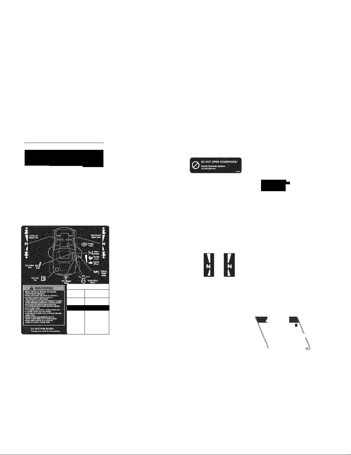
CALCOMANIAS DE SEGURIDAD Y
OPERACIÓN
Esta unidad fue diseñada y fabricada para ofrecerle ia seguridad
y confiabiiidad que usted esperaría de un líder en ia indus
tria de la fabricación de equipos motorizados para el exterior.
Aunque leer este manual y las medidas de segundad que
contiene le proporcionará el conocimiento básico necesario
para operar este equipo sin percances y eficazmente, hemos
colocado varias etiquetas de seguridad en la unidad para
recordarle esta importante información mientras usted opera
su unidad.
OPERATION
r.-
- ■
lD.S!brtEi9¡re:'• ' '
: • BEVERSETRÄVEL •
Calcomanía - Operación, Superior
No. de parte 1726429
ZZD
Calcomanía Interruptor de
Encendido
No. de parte
1726526
Debe leer cuidadosamente y acatar todos los mensajes de
PELIGRO, ADVERTENCIA, PRECAUCIÓN y de instrucciones
en su tractor y podadera. No seguir las instrucciones puede
resultar en lesiones personales ai cuerpo. ¡La información es
para su seguridad y es importante! Las calcomanías de
seguridad abajo están sobre su tractor y podadera.
Si pierde o se daña alguna de estas calcomanías, reempláce
las inmediatamente. Póngase en contacto con un Centro de
Partes y Servicio de Sears para obtener reposiciones.
Estas etiquetas son fáciles de aplicar y fungirán como cons
tantes recordatorios visuales para usted, y otros que puedan
llegar a usar el equipo, para que sigan las medidas de seguri
dad necesarias para una operación eficaz y sin percances.
LattWhael . '.. .
Calcomanía Sistema Hidráulico
'('pg'SHPwItmftShráni . -
' Controls Located -
' ' Beneath Hitch' '
Sellado
No. de parte 1726525
Calcomanía - Válvulas
de Seguridad de la
Transmisión
No. de parte 1715996
■1»
ROTAnHG BLADES CUT
OFF ARMS AND LEGS
STOfN«« MJifiH
CHILOREK ARE HEAR
ik DANGER 1
QPERATIRGOM SLOPES
MR BE OAMGEROUS.
tEÍGPERATOfi'SMAHLIAL
IFy6«CAtí)ffiIÍACK-tlí
AHILE, 60 HOTDAIVE AHII
EkONATOFERATE fiNSlORES
Calcomanía - Peligro/Advertencia, Inferior
No. de parte 1726430
Calcomanía - Ajuste
de Altura de Corte
No. de parte 1721197
Calcomanía - Freno
de Mano
No. de parte 1726529
/ROTATING CUTTING BLADE/
Do not ojierBte mowet
' without deflector or entire
' grass catcher in piace.
Calcomanía - Peligro,
Aspas Giratorias
No. de parte 1704277
Calcomanía - Control de
Velocidad -1 /D
No. de parte 1725671 I
1725670
ROTATING CUTTING BLADE\
Do not put hands orteet
under mower deck while
blade is rotating.
Calcomanía - Peligro,
Aspas Giratorias
No. de parte 1704276
38
Page 39

NUMEROS DE IDENTIFICACION
For Paris & Service
CRR$^rinN
Model No.:
Sears, Roebuck and Co.
3333 Beverly Road
Hoffman Esiate.s, IL 60179
' vv vv vv
1234Ì
Cuando se ponga en contacto con el centro de servi
cio para obtener partes de repuesto, servicio o infor
mación usted DEBERÁ proporcionar estos números.
Anote el nombre/número del modelo, números de identi
ficación del fabricante y los números de serie del motor
en el espacio provisto para su fácil acceso.
La chapa de identificación se encuentra en la cara inferior
de la cubierta del asiento. Incline la tapa del asiento hacia
adelante para ganar acceso a la chapa de identificación.
Para obtener respuestas a sus preguntas sobre el pro
ducto, llame al: 1-800-659-5917
Servicio Telefónico de Asistencia de Sears Craftsman,
5 am - 5 pm. Lunes - Sábado.
Call 1-SOO-4MY-HOME
www.sears.com
|¡!¡¡II!I!¡II¡¡
l!!!ll!l!lll!l
Nombre/Número de Descripción del Modelo
Número de INVENTARIO Número de SERIE de la Unidad
Fecha de Compra
■ DATOS: D E. R E:F E:B E N CIA .DE L: M OTO B-:
Marca del Motor Modelo del Motor
Tipo/Espec del Motor Código/Número de Serie del Motor
39
Page 40

ACCESORIQS OPCIONALES
* Recolector de Hierba con Bolsa Gemela
* Faro delantero
eo NTE NI DO D EL PAQ U ETE DE LITE R ATU R A
Instrucciones de
Disposición - Inglés
Setup
in e Easy Steps:
Troubleshooting
1
E
Instrucciones de
Disposición - Español
Command Series
CVff. Cl^ZíS, Cl^íS, CV1
CWSO. CV49H
VfíDiCíi CiEawímrt
Owner's Manual
Manual del Operador y Libro de
Partes - Ingiés/Español
Llaves Manual del Motor
40
Page 41

PRE-OPERACION
Leer el Manual del
Operador
Usted siempre debe leer y seguir las
instrucciones en el manual del
Operador. En este importante docu
mento encuentra información sobre
el debido cuidado, consejos de rendimiento y seguri
dad.
Siempre Verificar el
Nivel del Aceite
El motor en su tractor fue embarca
do, de fábrica, lleno con aceite 10W-
30 de peso para usar durante el
periodo de asentado del motor.
Siempre verifique el nivel del aceite antes de arrancar
el motor.
Llenar con Gasolina
FRESCA
¡El problema singular más común
de servicio es el combustible vicia
do o contaminado! El combustible
no debe tener más de 30 días.
Use un estabilizador de combustible para extender
la vida de su combustible y siempre almacene el
combustible en un envase plástico aprobado y sella
do para gasolina. La limpieza interior de combustible
do no está cubierta por su garantía.
Recargar la Batería
• Levante la tapa del asiento para
ganar acceso a la batería. Si la unidad
se envía a servicio después del mes y
año indicados en la fecha señalada en
la batería (en la parte superior) recar
gue la batería por una hora a 6-10 amps. Consulte la sec
ción de SERVICIO Y AJUSTES del manual del operador
respecto a la información de recarga de la batería.
Verificar Presión de
Llantas
Verifique la Presión de las Llantas.
Las llantas están demasiado
infladas para fines del embarque y
deben ponerse a la presión correcta
para que tengan una tracción óptima.
Presión de Llanta Trasera: 10-12 PSI (1.24-1.38 bar)
Presión de Llanta Delantera: 18-20 PSI (.69-.83 bar)
Empujar la Unidad
Fuera de la Caja de
Embalaje
Para empujar la unidad fuera de la
caja:
• Ponga las dos palancas de desem
brague de la transmisión en posición de EMPUJAR jalando
las palancas hacia atrás (las palancas se encuentran debajo
del enganche dei remolque).
• Corte las correas de acero que aseguran el tractor en la
tarima (6 correas).
• Ponga el freno de mano en posición de DRIVE.
• Ajuste la altura de corte de la podadera a la altura máxima.
• Doble a la mitad el cartón usado para el embalaje de la
unidad y colóquelo debajo de las ruedas frontales de la unidad.
• Empuje la unidad fuera de la caja de embalaje:
• Ponga las palancas de las válvulas de seguridad de la trans
misión de regreso en la posición de DRIVE (las palancas
hacia adelante).
Arrancar el Motor
• Estando sentado en el asiento
del operador, ponga el freno de
mano en PARK. Cerciórese de
que esté apagado el interruptor
PTO y que las palancas del con
trol de velocidad estén en posi
ción de PARK.
• Mueva el control de aceleración del motor comple
tamente hacia adelante a CHOKE.
NOTA: Es posible que si el motor está caliente no
requiera el ahogador. En este caso, ponga al con
trol de aceleración en FAST.
• Inserte la llave en el interruptor de encendido y
gírelo a START.
• Después de que arranque el motor, mueva grad
ualmente el control de aceleración de regreso a la
posición de FAST (ahogador abierto). Caliente el
motor dejándolo correr por lo menos por un minuto
antes de activar el interruptor PTO o conduciendo
la unidad.
• Después de calentar el motor, SIEMPRE opere la
unidad con el acelerador en la posición de FAST
mientras está podando el césped.
41
Page 42

OPERACION
Ajuste de
f Corte
Interruptor (llave)
de Encendido
Palancas de Velocidad ■
- Posición de DRIVE
Tapón del
Tanque de
Gasolina
Palancas de Velocidad ■
- Posición de PARK
|[||)ifP.Í Altura de
START
Palancas de
Desembrague de
Transmisión
Figura 1. Controles
FUNCIONES DE CONTROL
La información abajo describe brevemente la función de los controles individuales. Arrancar, detenerse, conducir y podar
el césped requiere del uso combinado de varios controles aplicados en secuencias específicas. Para aprender qué com
binaciones y secuencia de controles deben usarse para diversas tareas le rogamos que lea la sección completa.
Palancas de Velocidad
Estas palancas controlan la velocidad del tractor. La palanca
izquierda controla la rueda de tracción trasera izquierda y
palanca derecha controla la rueda de tracción trasera derecha.
Empujar las palancas hacia afuera, lejos del regazo del
operador las fija en posición de PARK (diagrama pequeño,
Figura 1). Jalar las palancas hacia adentro, encima del
regazo del operador las pone en posición de DRIVE.
Desde la posición de DRIVE, mover la palanca hacia
adelante aumenta la velocidad HACIA ADELANTE de la
llanta asociada. Jalar la palanca hacia atrás aumenta la
velocidad de REVERSA. Entre más se empuje una
palanca, más rápido girará la rueda de tracción.
Vea la PRÁCTICA DE MANEJC respecto a las instruc
ciones de conducción.
El acelerador controla la velocidad del motor. Siempre
opere con el acelerador en FULL al podar el césped. Mueva
la palanca hacia adelante hasta el freno mecánico para
acelerar en FULL (RÁPIDO). Mueva el acelerador hada
atrás para disminuir la velocidad del motor a IDLE (LENTO).
Cierre el ahogador para arrancar en frío. Abra el
ahogador una vez que el motor arranque. Es posible
que si el motor está caliente no requiera el ahogador.
Mueva la palanca hacia adelante más allá del freno
mecánico del acelerador en FULL para cerrar el
ahogador. Mueva la palanca de regreso hasta el freno
mecánico para abrir el ahogador.
42
Control de Aceleración
Ahogador
Page 43

Ajuste de Altura de Corte de Rodadora
Para ajustar la altura de corte, gire la manivela a la
derecha para subir la cubierta de la podadora y a la
Izquierda para bajar la cubierta de la podadora.
Interruptor de Encendido
El Interruptor de encendido arranca y detiene el motor;
tiene tres posiciones:
OFF (apagado) Detiene el motor y corta el
sistema eléctrico.
RUN (activo) Permite que el motor corra y suministra
energía al sistema eléctrico.
START (arrancar) Mueve el motor para que arranque.
NOTA: Nunca deje el interruptor de encendido en la posi
ción de RUN con el motor detenido. Esto drena la batería.
Medidor de Horas
El medidor de horas mide la cantidad de horas que la
llave lleva en la posición de RUN. El medidor de horas
hará que parpadee el indicador de cambio de aceite a
las 5 horas, y un aviso de lubricación cada 50 horas.
Estos avisos se restablecen automáticamente.
NOTA: El medidor de horas registra el paso del tiempo
cuando la llave está en posición de RUN, aun si el motor
no está encendido.
Interruptor PTO
El interruptor PTO (Eliminador de Energía) embraga y
desembraga un embrague eléctrico conectado al
cigüeñal del motor. Este embrague eléctrico conduce y
detiene la cubierta de la podadora. Para encender la
podadora, jale el interruptor hacia ARRIBA. Empuje el
interruptor hacia ABAJO para apagar la podadora. Tome
en cuenta que el operador debe estar sentado firmemente
en el asiento del conductor para que el PTO funcione.
Palancas de Desembrague de Transmisión
Las palancas de desembrague de la transmisión desacti
van las transmisiones para que la unidad pueda empu
jarse manualmente. Vea EMPUJAR LA UNIDAD
MANUALMENTE respecto a la información operacional.
kzJ Perilla de Ajuste del Asiento
El asiento puede ajustarse hacia adelante y atrás.
Incline el asiento hacia adelante, afloje la perilla de
ajuste, deslice el asiento a la posición deseada y apriete
la perilla.
Freno de Mano
DRIVE Suelta el freno de mano.
PARK Bloquea el freno de mano.
Tanque de Gasolina
Para quitar el tapón, gire a la izquierda.
SEGURIDAD GENERAL DE OPERACION
Antes de la primera operación:
• Asegúrese de leer toda la información en las secciones
de Seguridad y Operación antes de intentar operar el
tractor o la podadora.
• Familiarícese con todos los controles y cómo detener la
unidad.
• Conduzca en un área abierta sin podar el césped para
acostumbrarse a conducir la unidad.
Jale la palanca del freno de mano hasta engranar el
freno de mano (posición de PARK). Mueva la palanca
completamente hacia abajo para desengranar el freno
de mano (posición de DRIVE).
NOTA: Para arrancar la unidad, el freno de mano debe
estar en posición de PARK.
AADVERTENCIA
Si usted no entiende cómo funciona un control
específico, o no ha leído con detenimiento la sección
de FUNCIONES DE CONTROL, hágalo ahora.
NO intente operar el tractor sin antes
familiarizarse con la ubicación y la función de
TODOS ios controles.
43
Page 44

VERIFICACIONES ANTES DE ARRANCAR
• Verifique que el aceite del cárter esté en la marca de
lleno de la varilla de nivel de aceite.
• Ajuste la posición del asiento y cerciórese de poder
alcanzar todos los controles.
• Llene el tanque de gasolina con combustible fresco.
RECOMENDACIONES DE COMBUSTIBLE
Para operación diaria: Use sólo gasolina sin plomo donde la
calcomanía de la bomba Indique un octanaje de 87 o mayor.
El gasohol (hasta 10% de alcohol etílico, 90% de gasolina sin
plomo por volumen) está aprobado como combustible. El
Metilerbutil Éter (MTBE, por sus siglas en inglés} y las mezclas
de gasolina sin plomo (hasta un máximo de 15% MTBE por
volumen) están aprobados como combustible. Ninguna otra
mezcla de gasolina/alcohoi o gasolina/éter está aprobada. No
use aditivos para gasolina excepto el estabilizador de combustible.
Para almacenamiento: PRECAUCIÓN: Los combustibles
mezclados con alcohol (llamados gasohol o usando etanol o
metanol) puede atraer humedad que lleva a la separación y
formación de ácidos durante el almacenamiento. El gas acídico puede dañar la instalación de combustible de un motor
mientras está en almacenamiento.
Para evitar problemas con el motor, la instalación de combustible
debe vaciarse antes del almacenamiento de 30 días o más. Drene
el tanque de gasolina, arranque el motor y deje que corra hasta
que las líneas de combustible y el carburador estén vacíos. Use
combustible fresco en la próxima temporada. Vea las instruc
ciones de ALMACENAMIENTO para obtener información adicional.
Nunca use productos de limpieza para motores o carbu
radores en el tanque de gasolina o pueden ocurrir daños per
manentes. Para agregar combustible:
1. Quite el tapón de la gasolina (B, Figura 2).
2. Llene el tanque. No llene demasiado. Deje espacio en
el tanque para la expansión del combustible.
3. Instale y apriete manualmente el tapón de la gasolina.
Aadvertencia
Nunca permita que pasajeros se paseen en la unidad.
Antes de dejar el puesto del operador por cualquier
razón, accione el freno de mano, desacople el PTO,
detenga el motor y quite la llave.
Para reducir el peligro de un incendio, mantenga el
motor, el tractor y la podadora libre de césped, hojas
y aceite excesivo. No detenga ni estacione el tractor
sobre hojas secas, césped o materiales combustibles.
La gasolina es altamente inflamable y debe manejarse
con cuidado. Nunca llene el tanque cuando el motor
todavía está caliente por la reciente operación. No
permita que nadie se acerque con llamas abiertas,
cigarros o cerillos al área. Evite llenar demasiado y
quite lo derramado con un trapo.
Figura 2. Verificaciones Previas al Arranque
A. Perilla de Ajuste del Asiento
B. Tapón del Tanque de Gasolina
A ADVERTENCIA
Nunca opere en cuestas mayores a 17.6 por ciento (10°)
lo cual es una Inclinación de 3-1/2 pies (106cm)
verticalmente en 20 pies (607cm) horizontalmente.
Seleccione la velocidad lenta antes de conducir cuesta
arriba. Sea extremadamente precavido al operar en cuestas
con un recolector de hierba montado en la parte trasera.
Pode el césped de la cuesta de ARRIBA hacia ABAJO y
VICEVERSA, no de un lado al otro. Sea precavido al
cambiar de dirección y NO ARRANQUE NI SE
DETENGA EN UNA CUESTA.
A
No cargue este tractor de giro cero en un remolque
o camioneta usando dos rampas separadas. Sólo
use una sola rampa que por lo menos sea un pie más
ancho que las llantas de la parte trasera de este tractor.
Este tractor tiene un radio de giro cero y las llantas
pueden caer de las rampas, o el tractor puede vol
carse lesionando al operador o a los espectadores.
44
ADVERTENCIA - REMOLQUES
Page 45

PARO DE EMERGENCIA
En el caso de una emergencia, el motor puede detenerse
simplemente girando el interruptor de encendido a STOP.
Use este método sólo en situaciones de emergencia.
Para apagar el motor normalmente, siga el procedimien
to dado en DETENER EL TRACTOR Y EL MOTOR.
DETENER EL TRACTOR Y EL MOTOR
1. Regresar las palancas del control de velocidad a la
posición de PARK detendrá el movimiento del tractor.
2. Detenga la podadora presionando el interruptor PTO.
3. Mueva la palanca de freno de mano a la posición de PARK.
4. Mueva el control de aceleración a la posición de FAST
y ponga la llave de encendido en OFF. Quite la llave.
ARRANCAR EL MOTOR
1. Estando sentado en el asiento del operador, ponga el
treno de mano en PARK. Cerciórese de que esté
apagado el interruptor PTO y que las palancas del
control de velocidad estén en posición de PARK.
2. Mueva el control de aceleración del motor completa
mente hacia adelante a CHOKE.
NOTA: Es posible que si el motor está caliente no
requiera el ahogador. En este caso, ponga al control de
aceleración en FAST.
3. Inserte la llave en el interruptor de encendido y gírelo
a START
4. Después de que arranque el motor, mueva gradual
mente el control de aceleración de regreso a la posi
ción de FAST (ahogador abierto). Caliente el motor
dejándolo correr por lo menos por un minuto antes
de activar el interruptor PTO o conduciendo la unidad.
5. Después de calentar el motor, SIEMPRE opere la
unidad con el acelerador en la posición de FAST
mientras está podando el césped.
10. Detenga el motor (ver DETENER EL TRACTOR Y EL
EMPUJAR EL TRACTOR MANUAL
MENTE
6. Mueva la palanca del freno de mano a posición de
DRIVE.
7. Mueva las palancas del control de velocidad de la
posición de PARK a la posición de DRIVE (las palan
cas hacia adentro sobre el regazo del operador).
8. Empiece a podar el césped. Vea PRÁCTICA DE
MANEJO.
9. Cuando termine, gira el interruptor PTO a APAGADO.
MOTOR).
1. Apague el interruptor PTO, ponga el freno de mano
en PARK, apague el interruptor de encendido, quite
la llave y espere a que se detengan todas las partes
en movimiento.
2. Ubique las palancas de desembrague de la transmisión
(A y B, Figura 3) en la parte trasera de la unidad.
3. Jale las dos palancas hacia atrás y abajo para
desembragar las transmisiones (posición B, Figura 3).
4. Ponga el freno de mano en DRIVE.
Ahora puede empujar el tractor manualmente.
5. Después de mover el tractor, ponga el freno de mano
en PARK y mueva la palanca de desembrague de la
transmisión hacia arriba y adentro para volver a
embragar las transmisiones (posición A, Figura 3).
NO REMOLQUE EL TRACTOR
Remolcar la unidad dañará la transmisión.
G
No use otro vehículo para empujar o jalar la
unidad.
PODAR DEL CÉSPED
1. Coloque la palanca del freno de mano en la posición
de PARK. Cerciórese de que el interruptor PTO esté
APAGADO, que las palancas del control de velocidad
estén en posición de PARK y que el operador esté en
el asiento.
2. Ajuste la altura de corte de la podadora a la altura
deseada.
3. Arranque el motor (ver ARRANCAR EL MOTOR).
4. Ponga el acelerador en FAST.
5. Encienda el interruptor PTO para accionar la cubierta
de la podadora.
Figura 3. Palanca de Desembrague de la Banda
A. Posición de Drive
B. Posición de Empujar
45
Page 46

PRÁCTICA DE MANEJO -
MANEJO BÁSICO
ADVERTENCIA: Nunca opere en cuestas mayores a 17.6%
(10°). Vea OPERACIÓN EN CUESTAS en la sección de
seguridad. Los tractores de giro cero operan de modo difer
ente a otros vehículos de cuatro ruedas. Las ruedas de trac
ción también son sus ruedas de dirección. Si usted no puede
conducir la unidad en una colina, usted no podrá dirigir la
unidad en eila. Operar unidades de giro cero en cuestas
requiere de precauciones extremas.
Los controles de palanca del tractor de giro cero son muy sen
sibles, y aprender a dominar los movimientos de avance, rever
sa y vuelta del tractor con eficiencia y sin problemas requiere
práctica.
Dedique algo de tiempo probando las siguientes maniobras y
para familiarizarse con cómo acelera, se traslada y dirige la
unidad - antes de empezar a podar del césped - es absoluta
mente esencial para sacarle el mayor provecho al tractor de
giro cero.
Encuentre un área lisa y plana en su jardín — un área con
mucho espacio para maniobrar. (Antes de empezar quite del
área cualquier objeto, gente y animales.) Opere la unidad a
media aceleración durante esta sesión de práctica (SIEMPRE
opere con el acelerador en FULL al podar el césped), y gire
lentamente para evitar que derrapen las llantas y se dañe su
jardín.
Le sugerimos que empiece con el procedimiento de traslado
sin problemas a la derecha, y luego siga con las maniobras de
avance, reversa y vuelta.
Usted debe poner el freno de mano en ORIVE antes de mover
las palancas de control fuera de la posición de PARK.
A ADVERTENCIA
No pode el césped en reversa a menos que sea absolu
tamente necesario. Siempre mire hacia abajo y hacia
atrás antes de echarse en reversa y mientras lo hace.
Traslado sin prob
lemas
Los controles de palanca
del tractor de giro cero son
altamente sensibles.
El MEJOR método de
manejar las palancas del
control de velocidad es en
tres pasos - como se
muestra en la Figura 4.
PRIMERO coloque sus
manos en las palancas
como se muestra.
SEGUNDO, para avanzar
empuje gradualmente la
palanca hacia adelante con
sus palmas.
TERCERO, para acelerar
mueva las palancas más
hacia adelante. Para bajar
suavemente la velocidad,
mueva las palancas lenta
mente hacia atrás en direc
ción de neutral.
Figura 4. Mover las
Palancas de Control
Gradualmente
Práctica en el Manejo Hacia Adelante
Gradualmente mueva las dos palancas del control de velocidad
HACIA ADELANTE de modo uniforme lejos del neutral.
Desacelere y repita.
Reverse TraveI Practica
MIRE HACIA ATRÁS Y ABAJO, luego mueva gradualmente las
dos palancas del control de velocidad HACIA ATRÁS de modo
uniforme lejos del neutral. Desaceiere y repita.
NOTA: Practique echarse en reversa durante varios minutos
antes de intentar hacerlo cerca de algún objeto. El tractor gira
tan abruptamente en reversa como cuando va hacia adeiante,
y andar en reversa en línea recta requiere de práctica.
Manejo Hacia
Adelante
Manejo en Reversa
Figura 5. Manejo Hacia Adelante Figura 6. Manejo en Reversa
46
Page 47

Práctica de dar Vuelta en una Esquina
Práctica de Vuelta en el Lugar
Mientras viaja hacia adelante permita que una palanca
regrese gradualmente en dirección del neutral. Practique
varias veces antes de podar el césped.
NOTA: Para evitar girar directamente sobre la banda de
rodamiento, es mejor mantener las dos ruedas en mar
Hacer un "giro cero" significa girar en el mismo lugar.
Para dar la vuelta en el mismo lugar, gradualmente
mueva la palanca de control de velocidad hacia adelante
de neutral y una palanca hacia atrás del neutral
simultáneamente. Repita varias veces.
cha hacia adelante aunque sea ligeramente.
Ejecutar Vueltas
Vuelta en el
Mismo Lugar
Figura 7. Vuelta a la Derecha Figura 8. Vuelta en el Mismo Lugar
MANEJO AVANZADO
Ejecutar un Giro Cero al Final de la Fila
La habilidad única de su tractor de giro cero de
dar vuelta en su lugar le permite dar la vuelta al
final de una fila de corte en vez de tener que
detenerse y hacer una vuelta en U antes de ini
ciar con la siguiente fila.
Por ejemplo, para ejecutar un giro cero de final
de fila a la derecha:
1. Desacelere al final de la fila.
2. Mueva la palanca de control velocidad
IZQUIERDA ligeramente hacia adelante
mientras que mueve la palanca de control
velocidad DERECHA de regreso al centro y
luego ligeramente de regreso del centro.
3. Empiece de nuevo a podar el césped hacia
adelante.
Esta técnica gira el tractor a la DERECHA y se
traslapa ligeramente con la fila recién cortada eliminando la necesidad de regresar y cortar de
nuevo el césped omitido.
A medida que se familiarice más y tenga experi
encia con la operación del tractor de giro cero,
usted aprenderá más maniobras que le harán
más fácil y agradable el podado del césped.
¡Recuerde que entre más practique, mejor
controlará el tractor!
Figura 9. Ejecutar una Vuelta al Final de la Fila
47
Page 48

REMOCIÓN E INSTALACIÓN DE LA
CUBIERTA DE LA RODADORA
NOTA: Ejecute la remoción e instalación de la podadera sobre
una superficie dura y nivelada como un piso de concreto.
A ADVERTENCIA
Accione el freno de mano, desacople el PTO,
detenga el motor y quite la llave antes de intentar
instalar o quitar la podadera.
Quitar la Cubierta de la Rodadora
1.
Apague el PTO, ponga el freno de mano en PARK,
apague el encendido, quite la llave y espere a que se
detengan todas las partes en movimiento.
2.
Gire las ruedas delanteras del tractor hacia adelante.
3.
Coloque la manivela de ajuste de la altura de la
podadora (D, Figura 10) en la posición de corte más
bajo.
Libere la tensión en la banda de tracción usando la
palanca de desembrague de la banda en la podadera
(E, Figura 10) y quite la banda de tracción de la
polea del motor.
5.
Desconecte el enganche frontal quitando la varilla y
el clip del enganche (A, Figuras 10 y 11), y levantar
el enganche de la podadera (B) hacia y fuera del col
lar de fijación del enganche del tractor (D).
6.
Deslice la cubierta de la podadera hacia adelante
hasta que los soportes de la podadera trasera (C)
desacoplen el bastidor del tractor.
7.
Deslice la cubierta de la podadera hacia afuera
desde abajo del lado derecho del tractor.
Instalar la Cubierta de la Rodadora
1.
Gire las ruedas delanteras del tractor hacia adelante.
2.
Coloque la manivela de ajuste de la altura de corte
(D, Figura 10) en la posición de corte más bajo.
3.
Deslice la cubierta de la podadera abajo del lado
derecho del tractor. Deslice la podadera hacia atrás
asegurándose de que los soportes de la podadera
trasera (C, Figura 11) se deslicen arriba de las ram
pas en el bastidor. La parte trasera de la podadera
es apoyada por estas rampas del bastidor.
4.
Cuelgue el enganche de la podadera (B, Figura 11)
en el collar de fijación del enganche del tractor (D) y
asegure la varilla y el clip del enganche (A).
5.
Use la palanca de desembrague de la banda en la
podadera (E, Figura 12) para liberar la tensión en la
polea tensora de la podadora e instale la banda de
tracción como se muestra en la Figura 1.
Figura 10. Componentes de la Podadora
A. Varilla y Clip del Enganche
Enganche de la Podadora
B.
Soportes de la Podadora Trasera
c.
Manivela de Ajuste de la Altura de Corte
D.
Palanca de Desembrague de la Banda en la Podadora
E.
Figura 11. Componentes dei Enganche de la Podadora
A. Varilla y Clip del Enganche
B. Enganche de la Podadora
C. Soportes de la Podadora Trasera
D. Collar de Fijación del Enganche del Tractor
Figura 12. Disposición de Banda de Podadora
A. Polea del Motor
B. Banda de Tracción de la Podadora
C. Polea Tensora del Lado Posterior
D. Polea Tensora en V
E. Palanca de Desembrague de la Banda de Podadora
F. Polea Motriz de la Podadora
48
Page 49

MANTENIMIENTO
PROGRAMA DE MANTENIMIENTO
El siguiente programa debe seguirse para el cuidado normal de su tractor y podadora. Será necesario que mantenga
un registro de su tiempo de operación. Determinar el tiempo de operación se logra fácilmente al observar el tiempo
transcurrido en el medidor de horas.
ELEMENTOS DE MANTENI
MIENTO DELTRACTOR
Limpiar despojos del tractor y del com
partimiento del motor *
Limpiar despojos del área de enfriamien
to del motor y del filtro de aire *
Verificar presión de las llantas
Lubricar tractor y podadora *
Limpiar cubierta y verificar/reemplazar
aspas de podadora
Limpiar batería y cables
Verificar sistema de seguridad dei tractor **
Verificar / ajustar embrague del PTO
Antes de
cada uso
ELEMENTOS DE MANTENI
MIENTO DEL MOTOR
Verificar nivel de aceite del motor
Dar servicio al pre-limpiador del filtro de aire *
Reemplazar filtro de aire *
Cambiar aceite del motor *
Reemplazar bujía
Reemplazar filtro de gasolina
Cambiar aceite del motor y filtro *
Cada otoño
y primavera
#
•
8
horas25horas
• •
• •
100
horas
e
•
•
•
200
horas
•
e
•
•
•
e
•
* Con más frecuencia en climas calientes (superiores a 85°F: 30°C) o condiciones de operación polvorientas.
** Verifique la función del sistema de seguridad después de almacenar la unidad por 30 días o más.
49
Page 50

Elementos de Mantenimiento
del Tractor
LIMPIAR DESPOJOS DEL TRACTOR Y
DEL COMPARTIMIENTO DEL MOTOR
Intervalo de Servicio: Antes de cada uso.
PRECAUCIÓN: Si no se quitan los despojos del com
partimiento del motor y otras superficies calientes,
se crea un peligro de incendio. Antes de arrancar la
unidad al inicio de la sesión de podado de césped, elim
ine cualquier hierba cortada, mugre, hojas u otros
despojos de la unidad. También limpie el interior del
compartimiento del motor.
LIMPIAR DESPOJOS DEL AREA DE
ENFRIAMIENTO DEL MOTOR Y DEL FIL
TRO DE AIRE
Intervalo de Servicio: Antes de cada uso.
PRECAUCIÓN: Si no se quitan ios despojos del com
partimiento del motor y otras superficies calientes,
se crea un peligro de incendio. Antes de arrancar la
unidad al inicio de la sesión de podado de césped, lev
ante el asiento y limpie cualquier despojo de la rejilla de
admisión en la parte superior del motor (A, Figura 13), el
abanico de enfriamiento expuesto del motor y alrededor
de la instalación del filtro de aire. También abra la tapa
del filtro de aire (B) y elimine cualquier suciedad que se
haya acumulado en el compartimiento del filtro de aire.
VERIFICAR PRESION DE LAS LLANTAS
B. Cubierta del Filtro de Aire
Llanta Presión
Delantera 18-20 psi (1.24-1.38 bar)
Trasera 10-12 psi (.69-.83 bar)
Intervalo de Servicio: 25 horas.
La presión de las llantas debe revisarse periódicamente
y mantener en los niveles mostrados en la Figura 14.
Tome en cuenta que las presiones pueden diferir ligera
mente de la "Inflación Máx" estampada a los lados de
las llantas. Las presiones mostradas ofrecen una trac
ción apropiada, mejor calidad de corte y vida extendida
para las llantas.
Figura 14. Presión de las Llantas
50
Page 51

LUBRICACION
Intervalo de Servicio: 25 horas.
Lubrique la unidad en los lugares mostrados en las
Figuras 15 a 17 así como en los siguientes puntos de
lubricación.
Grasa:
■ engrasadores de la rueda delantera
■ bujes de la rueda delantera
■ pivotes de la podadera
■ árboles de sujeción de la podadera
Use engrasadores cuando estén presentes.
No todas las grasas son compatibles. Use grasa de litio
de tipo automotriz.
Aceite:
> pivote del bastidor trasero
> acoplamiento hidráulico
i
> sistema de ajuste del asiento
> acoplamiento del freno
> puntos del pivote del bastidor
> acoplamiento del ajuste de altura de la cubierta
de la podadera
Generalmente, todas las partes de metal para podado
deben engrasarse donde entran en contacto con otras
partes. No ponga aceite ni grasa en las bandas y
poleas. Recuerde limpiar con un trapo los acoples y
superficies antes y después de la lubricación.
Figura 15. Lubricación de la Rodadora
51
Page 52
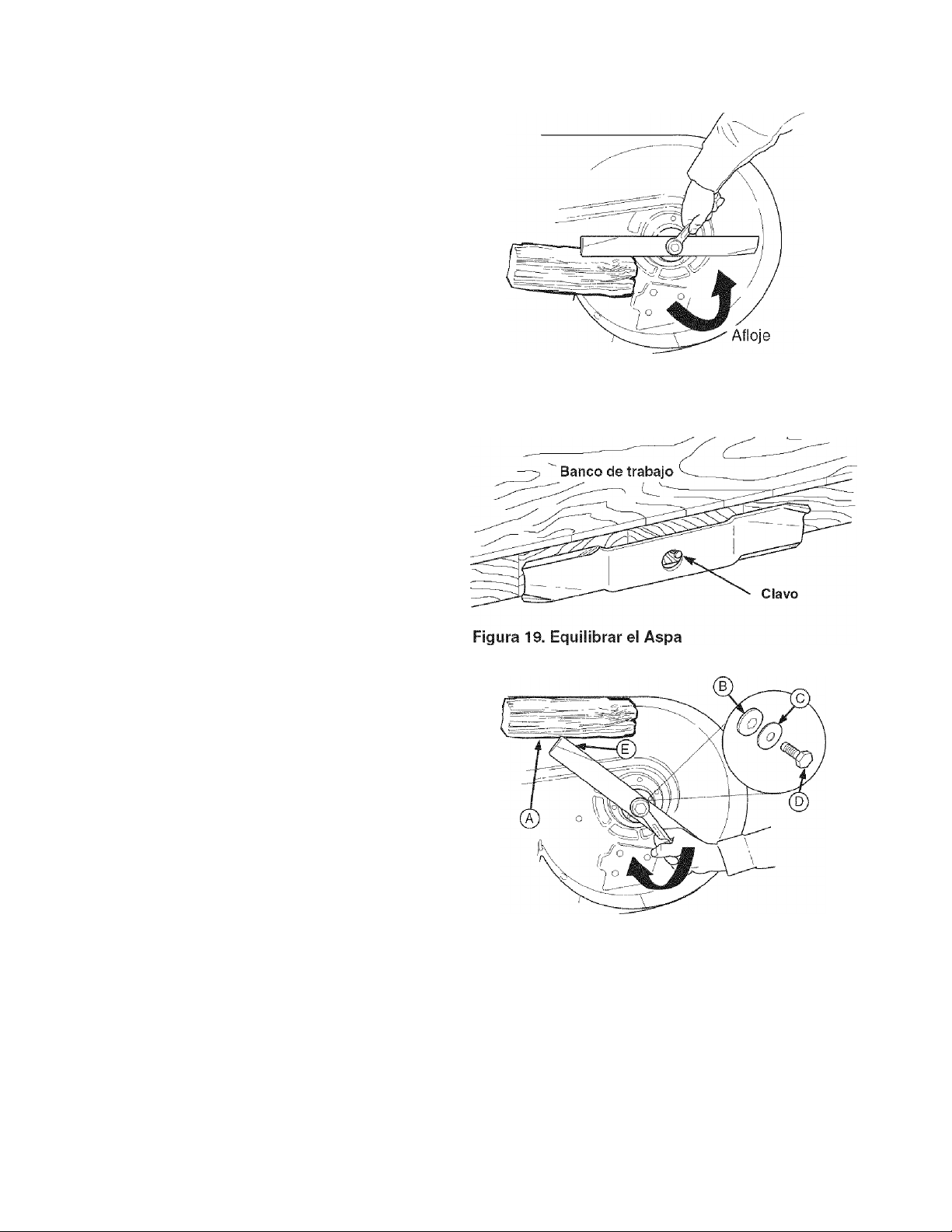
LIMPIAR CUBIERTA Y VERIFICAR/ REEMPLAZAR ASPAS DE PODADORA
Intervalo de Servicio: 25 horas o según se requiera.
A ADVERTENCIA----------------
Para su seguridad personal, no maneje las aspas
afiladas de la podadora con las manos
descubiertas. El manejo imprudente o indebido
de las aspas puede resultar en lesiones graves.
A ADVERTENCIA
Para su seguridad personal, los tornillos de cabeza
hexagonal para montar las aspas deben instalarse con
una arandela acanalada y una arandela elástica, y
luego apretar fijamente. Apriete el tornillo de cabeza
hexagonal para montar el aspa a un par de torsión de
45 - 55 ft. Ibs. (61 - 75 N.m.)
1. Quite la cubierta de la podadora (vea "Remoción de
la cubierta de la podadora" en la sección de
OPERACIÓN).
2. Vea la Figura 18. Quite el aspa para inspeccionarla o
para ganar acceso seguro al lado inferior de la
cubierta de la podadora. Use un bloque de madera
para evitar que gire el aspa mientras afloja el tornillo
de cabeza hexagonal girándolo a la izquierda.
3. Quite el tornillo de cabeza hexagonal (D, Figura 20),
arandela elástica (C), arandela acanalada (B) y aspa.
4. Limpie el lado inferior de la cubierta de la podadora.
5. Inspeccione las aspas para ver que no tengan
muescas o rebordes desafilados. Use una lima para
afilar el aspa a un filo cortante. Si el aspa está daña
da, debe reemplazarla.
6. Equilibre el aspa como se muestra en la Figura 19.
Centre el orificio del aspa con un clavo lubricado con
una gota de aceite. Un aspa equilibrada permanecerá
nivelada. Si el aspa no está equilibrada, siga afilando
el lado pesado hasta que esté equilibrada.
7. Reinstale el aspa con las aletas de izado (E, Figura
20) apuntando arriba hacia la cubierta de la podadora
como se muestra.
8. Reinstale la arandela acanalada (B, Figura 20), aran
dela elástica (C) y tornillo de cabeza hexagonal (D).
Use un bloque de madera (A) para evitar que el aspa
gire mientras aprieta el tornillo de cabeza hexagonal
(D) a 45-55 ft. Ibs. (61-75 N.m). Gire el tornillo de
cabeza hexagonal a la derecha para apretarlo.
Figura 18. Remoción dei Aspa
Figura 20. Instalación del Aspa
A. Bloque de Madera de 4x4
B. Arandela Acanalada
C. Arandela Elástica
D. Tornillo de Cabeza Hexagonal del Aspa
E. Aletas de izado
52
Page 53

LIMPIAR BATERIA Y CABLES
A ADVERTENCIA
Tenga cuidado al manejar la batería. Evite
derramar el electrolito. Mantenga llamas y
chispas lejos de la batería. Cuando quite o instale
los cables de la batería, desconecte PRIMERO el
cable negativo y conéctelo al ÚLTIMO. Si no se
hace en este orden, la terminal positiva puede
causar un cortocircuito al bastidor con una
herramienta.
Siempre use lentes de seguridad y guantes
cuando maneje baterías.
intervalo de Servicio: 200 horas
1. Desconecte los cables de la batería, primero el cable
negativo (B, Figura 21).
2. Quite la banda de goma que sujeta la batería y quite
la batería
3. Limpie la batería y el compartimiento de la batería
con una solución de bicarbonato de sodio y agua.
4. Limpie las terminales de la batería y los extremos del
cable con un cepillo de alambre hasta que brillen.
5. Reinstale la batería y sujétela con la banda de goma.
6. Reconecte los cables de la batería: primero conecte
el cable positivo (vea A, Figura 21), luego conecte el
cable negativo (B).
7. Aplique una capa de parafina o grasa no conductora
a los extremos del cable y a las terminales de la
batería.
VERIFICAR SISTEMA DE
A
Intervalo de Servicio: 200 Horas y Cada Primavera y Otoño
Esta unidad está equipada con interruptores de intercierre de
seguridad. Estos sistemas de seguridad están presentes
para su seguridad. No intente eludir los interruptores de
seguridad y nunca manipule los dispositivos de seguridad.
Verifique su operación con regularidad.
Verificaciones de SEGURIDAD Operacional
PRUEBA 1 — EL MOTOR NO DEBE ARRANCAR SI:
• El interruptor PTO está en ON, O BIEN
• El freno de mano está en posición de DRIVE, O
• Las palancas del control de velocidad no están en posi
ción de PARK.
PRUEBA 2 —EL MOTOR DEBE ARRANCAR Si:
• El interruptor PTO está en OFF, Y
• El freno de mano está en posición de PARK, Y
• Las palancas del control de velocidad están fijas en posi
ción de PARK.
PRUEBA 3 - EL MOTOR DEBE APAGARSE SI:
• El operador se levanta del asiento con el PTO en ON, O
• El operador se levanta del asiento con el freno de mano
en posición de DRIVE, O BIEN
• El operador mueve las palancas del control de velocidad
fuera de la posición de PARK antes de poner el freno de
mano en DRIVE.
PRUEBA 4-VERIFICACIÓN DE FRENO DE ASPAS
Las aspas y la banda de tracción de la podadera
deben detenerse por completo en un lapso de cinco
segundos después de poner el interruptor PTO en
OFF. Si la banda de tracción de la podadera no se
detiene en cinco segundos, póngase en contacto con
el Centro de Partes y Reparaciones de Sears.
SEGURIDAD DEL TRACTOR
Figura 21. Compartimiento del Motor
A. Cable Positivo (+) de la Batería
B. Cable Negativo (-) de la Batería
NOTA: Una vez que se haya detenido el motor, debe
poner el interruptor PTO en OFF, el freno de mano en
PARK y las palancas del control de velocidad fijas en la
posición de PARK para que pueda arrancar el motor.
A ADVERTENCIA
Si la unidad no pasa una prueba de seguridad,
no la opere. Visite un Centro de Partes y
Reparaciones de Sears. Bajo ninguna circuns
tancia debe usted intentar vencer la finalidad
del sistema del intercierre de seguridad.
53
Page 54

VERIFICAR/AJUSTAR EMBRAGUE DEL PTO
A ADVERTENCIA
Para evitar lesiones graves, sólo haga los ajustes
con el motor detenido, la llave quitada y el tractor
en terreno nivelado.
Intervalo de Servicio: 200 horas.
El embrague dei PTO se embraga y desembraga con el
interruptor PTO. El embrague suministra la energía y
frena las aspas de la podadera. Verifique el ajuste del
embrague del PTO cada 200 horas de operación.
También realice el siguiente procedimiento si se barre el
embrague, no embraga o si instaló un embrague nuevo.
1. Quite la llave del interruptor de encendido y
desconecte los cables de las bujías para evitar un
posible arranque accidental mientras ajusta el PTO.
2. Vea la Figura 22. Tome nota de la posición de las 3
ventanas de ajuste (A) en el lado del disco portafreno
y las tuercas mecánicas de ajuste (B).
3. Inserte una lámina calibradora (C) de .012"-.015"
(2.5-4mm) por cada ventana, colocando el calibrador
entre la cara del rotor y la cara del armazón como se
muestra en la Figura 23.
4. Alternativamente apriete las tuercas de ajuste (B,
Figura 22) hasta que la cara del rotor y la cara del
armazón apenas hagan contacto con el calibrador.
5. Verifique las ventanas para ver que la tensión sea
igual cuando el calibrador se introduce y se saca, y
haga los ajustes necesarios apretando o aflojando
las tuercas de ajuste.
NOTA: El espacio vacío existente entre el rotor y el
armazón puede variar aún después de realizar el pro
cedimiento de ajuste. Esto se debe a las variaciones
dimensionales de los componentes y es una condición
aceptable.
6. Verifique el tiempo en que se detienen las aspas de
la podadera. Las aspas y la banda de tracción de la
podadera deben detenerse por completo en un lapso
de cinco segundos después de apagar el interruptor
PTO eléctrico. Si el ajuste no termina el problema de
frenado de la podadera, reemplace el embrague
eléctrico del PTO.
------------
Figura 22. Ajuste del Embrague del PTO
A. Ventana de Ajuste (Ctd. 3, se muestra
B. Tuerca de Ajuste
Figura 23. Ajustar Embrague del PTO
A. Ventana
B. Tuerca de Ajuste
C. Lámina Calibradora
una)
54
Page 55

Elementos de iVIantenimiento
del iViotor
VERIFICAR NIVEL DE ACEITE DEL MOTOR
Intervalo de Servicio: Antes de cada uso y cada 8 horas.
1. Apague el motor y ponga el freno de mano en PARK.
2. Limpie el área alrededor de la varilla de nivel de aceite
(C, Figura 25).
3. Quite la varilla de nivel de aceite (C) y límpiela con una
toalla de papel.
4. Inserte de nuevo la varilla de nivel de aceite en el motor,
pero no enrosque de nuevo el tapón en el tubo (D).
5. Quite la varilla de nivel de aceite y estudie el nivel del
aceite. El nivel del aceite debe estar entre las marcas
"F" y "L" (D). Si no, agregue aceite conforme a la tabla
de recomendaciones de aceite (Figura 24).
CAMBIAR EL ACEITE DEL MOTOR
Intervalo de Servicio: 100 horas.
Capacidad del Aceite: .95 de cuarto de galón (.90 litros)
con cambio de filtro de aceite.
Nota: Cambie el aceite de! motor mientras el motor está
tibio. Deje correr el motor por unos minutos, luego apague
el motor y deje que enfríe de caliente a tibio.
1. Limpie el área alrededor de la varilla de nivel de aceite
(C, Figura 25) y del tubo de drenaje de aceite (A).
2. Quite el tapón de drenaje de aceite (A) del extremo del
tubo de drenaje de aceite. Quite la varilla de nivel de
aceite (C). Conceda un buen tiempo para que termine
de drenar.
3. Reinstale el tapón de drenaje de aceite (A).
4. Llene el cárter con aceite. Vea arriba VERIFICAR
NIVEL DE ACEITE DEL MOTOR.
CAMBIAR ACEITE DEL MOTOR Y FILTRO
Intervalo de Servicio: 200 horas.
Capacidad del Aceite: .95 de cuarto de galón (.90 litros)
con cambio de filtro de aceite.
Nota: Cambie el aceite del motor mientras el motor está
tibio. Deje correr el motor por unos minutos, luego apague
el motor y deje que enfríe de caliente a tibio.
1. Limpie el área alrededor de la varilla de nivel de aceite
(C, Figura 25) y el drenaje del aceite (A).
2. Quite el tapón del drenaje del aceite (A) y la varilla de
nivel de aceite (C). Conceda un buen tiempo para que
termine de drenar.
3. Quite el filtro del aceite (B). Tire el filtro a la basura.
4. Voltee el filtro nuevo y llénelo con aceite fresco. Permita
que el aceite trasmine en el filtro nuevo por dos minutos.
55
Use aceite de Servicio clasificado para API de
Clase SG, SFI, SJ o mejor con viscosidad SAE.
°C -30 -18 -7 0 4 16 27 38
■* Los aceites sintéticos recomendados ofrecen un mejor arranque a temperatura
menores a-10"'F
Figura 24. Aceite de Motor Recomendado
Figura 25. Cambio de Aceite
A. Tubo de Drenaje de Aceite
B. Filtro de Aceite
C. Varilla de Nivel de Aceite
D. Verificar Nivel del Aceite
5. Usando una gota de aceite en la punta del dedo, moje
el empaque de goma en la parte inferior del filtro nuevo.
6. Tire el aceite del filtro e instale el filtro en la base del
filtro. Gire el filtro a la derecha hasta que el empaque
de goma tope con la base del filtro. Luego dé 2/3 a 1
vuelta completa más.
7. Reinstale el tapón de drenaje de aceite (A).
8. Llene el cárter con aceite. Vea arriba VERIFICAR
NIVEL DE ACEITE DEL MOTOR.
9. Pruebe el motor para verificar que no haya fugas.
Detenga el motor por 1 minuto, luego vuelva a veri
ficar el nivel del aceite.
Page 56

DAR SERVICIO AL PRE-LIMPIADOR DEL
FILTRO DE AIRE
Intervalo de Servicio: 25 horas o según se requiera.
1. Afloje la perilla de la tapa del filtro de aire y quite la
tapa (A, Figura 26). Limpie cualquier suciedad en el
interior y alrededor del filtro de aire. Inspeccione la
condición de las superficies selladas del elemento
del filtro de aire (D) y la base del filtro. Reemplace
cualquier parte dañada.
2. Quite el pre-limpiador de espuma (B) del elemento
del filtro de aire (D).
3. Lave el pre-limpiador (B) con agua tibia y detergente.
Enjuague con abundante agua. Elimine el exceso de
agua. NO lo exprima. Permite que el pre-limpiador
seque al aire.
4. Sature el pre-limpiador con nuevo aceite para motor.
Elimine el exceso de aceite. NO lo exprima. Apriete
el pre-limpiador contra una toalla de papel hasta
eliminar todo el exceso de aceite.
5. Reinstale el pre-limpiador (B) sobre el filtro de aire
(D).
6. Reinstale la tapa del limpiador de aire (A).
REEMPLAZAR EL FILTRO DE AIRE
Intervalo de Servicio: 100 horas o según se requiera.
1. Afloje la perilla de la tapa del filtro de aire y quite la
tapa (A, Figura 26). Limpie cualquier suciedad en el
interior y alrededor del filtro de aire. Inspeccione la
condición de las superficies selladas del filtro de aire
(D) y la base del filtro. Reemplace cualquier parte
dañada.
2. Quite el pre-limpiador de espuma (B) del elemento
del filtro de aire. Dé servicio al pre-limpiador como
se describe arriba en DAR SERVICIO AL PRE
LIMPIADOR DEL FILTRO DE AIRE.
3. Quite la tuerca de mariposa (C). Quite y reemplace
el filtro de aire (D).
4. Reinstale la tuerca de mariposa (C) y el pre-limpiador
(B).
5. Reinstale la tapa del limpiador de aire (A).
Figura 26. Ensamble del Filtro de Aire
A. Tapa y Periiia del Filtro de Aire
B. Pre-Limpiador de Espuma
C. Tuerca de mariposa con Material de Bloqueo
D. Filtro de Aire
E. Sello de Goma
F. Perno
56
Page 57

REEMPLAZAR BUJIA
Intervalo de Servicio: 200 horas.
Bujía de Repuesto: Champion RC12YC o equivalente
Entrehierro de Bujía: .040" (Imm)
1. Detenga el motor y permita que se enfríe.
2. Limpie el área alrededor de la bujía (A, Figura 28).
3. Quite la bujía e inspecciónela. Si está dañada o des
gastada, reemplácela.
4. Verifique el entrehierro de la bujía. El entrehierro (de
una bujía nueva o usada) debe ser de .040" (vea la
Figura 27).
5. Reinstale la bujía en la culata del cilindro (Figura 28).
Apriete la bujía a un par de torsión de 28-32 ft. Ibs.
(38-43 N.m.).
REEMPLAZAR FILTRO DE GASOLINA
A ADVERTENCIA----------------
La gasolina es altamente inflamable y debe manejarse con
cuidado. Nunca llene el tanque cuando el motor todavía
está caliente por la reciente operación. No permita que nadie
se acerque con llamas abiertas, cigarros o cerillos al área.
Evite llenar demasiado y quitar lo derramado con un trapo.
.040"
Figura 27. Entrehierro de la Bujía
No quite el filtro de la gasolina cuando el motor está
caliente, ya que la gasolina que se derrame se puede
incendiar. NO extienda las abrazaderas de la manguera más
allá de lo necesario. Asegúrese de que las abrazaderas
agarren firmemente la manguera sobre el filtro después
de la instalación.
Intervalo de Servicio: 200 horas.
El filtro de la gasolina se encuentra en la tubería del com
bustible entre el tanque de gasolina y el carburador. Si el
filtro está sucio o tapado, cámbielo de la siguiente manera:
1. Detenga el motor y permita que se enfríe la unidad.
2. Desconecte el cable negativo de la batería de la termi
nal negativa (C, Figura 28).
3. Usando unas pinzas de cierre, quite las abrazaderas de
la tubería del combustible de los dos lados del filtro de
la gasolina (B).
4. Coloque un contenedor adecuado abajo del filtro de la
gasolina para atrapar el combustible derramado.
5. Extienda las abrazaderas del filtro de la gasolina sólo lo
necesario para quitar las abrazaderas. Aleje las
abrazaderas del filtro de la gasolina.
6. Quite y reemplace el filtro de la gasolina.
7. Sujete el filtro de la gasolina con las abrazaderas origi
nales y quite las pinzas de cierre.
8. Conecte el cable negativo de la batería (C) cuando ter
mine.
Figura 28. Compartimiento del Motor
A. Bujía
B. Filtro de la Gasolina
C. Terminal y Cable Negativos de la Batería
57
Page 58
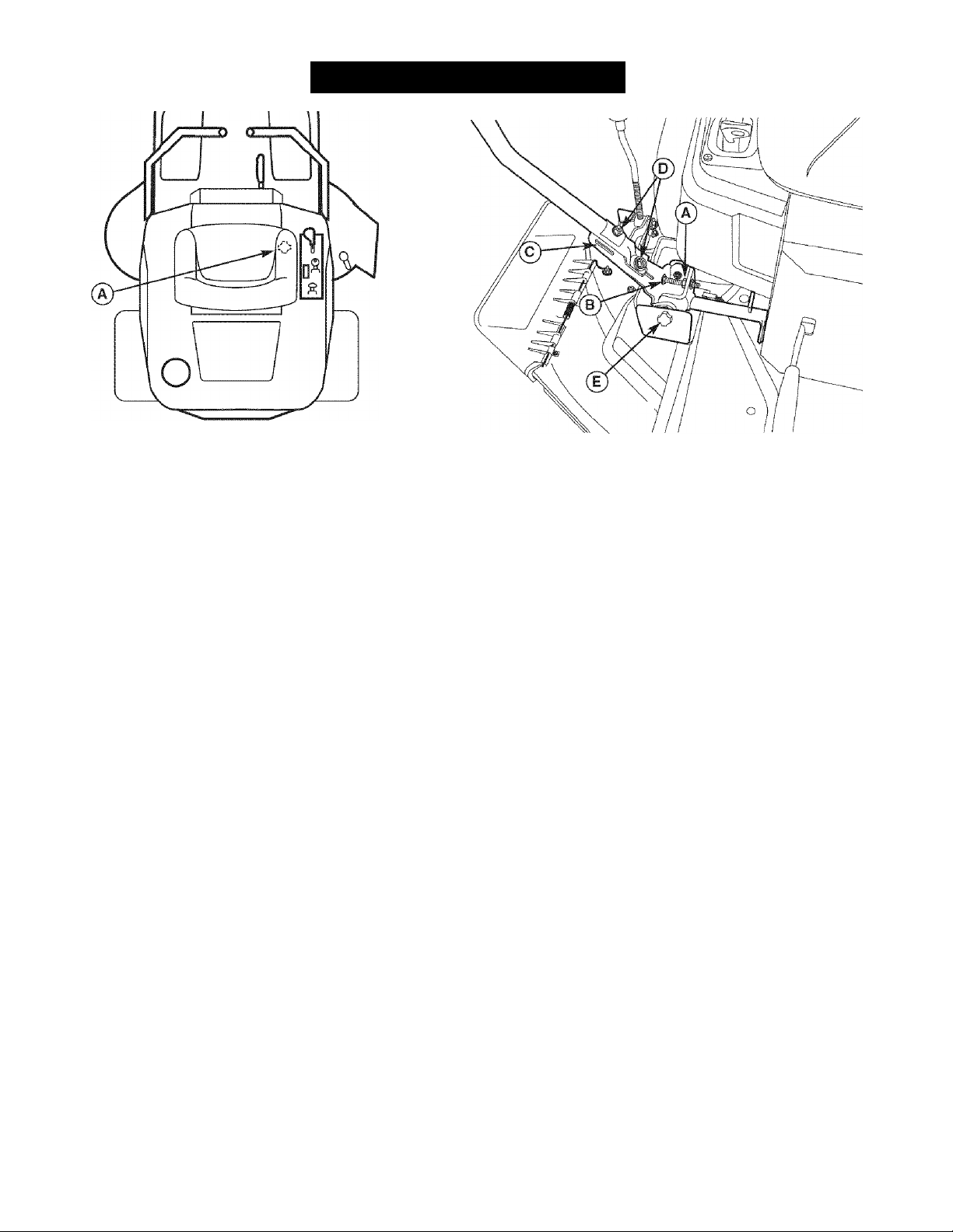
SERVICIO Y AJUSTES
Figura 29. Ajuste del Asiento
Perilla de Ajuste del Asiento (Abajo de la Cubierta
del Asiento)
AJUSTES AL ASIENTO
El asiento y las palancas del control de velocidad deben
estar ajustados de modo que las palancas del control de
velocidad puedan moverse por el arco completo de
movilidad.
Figura 30. Ajuste de las Palancas de Control
A. Contratuerca
B. Tornillo de Cabeza Redonda
C. Ranura Delantera
D. Pernos de Montaje
E. Perilla
El asiento puede ajustarse hacia adelante y hacia atrás.
Afloje la perilla de ajuste (A, Figura 29) ubicada abajo de
la cubierta del asiento, mueva el asiento a la posición
deseada, luego apriete la perilla.
AJUSTE DE PALANCA DE CONTROL DE VELOCIDAD
Las palancas de control tienen tres ajustes:
Para Ajustar la Altura de las Palancas de Control: Jale las
palancas hacia adentro, encima del regazo del operador a la
posición de ORIVE. Afloje los pernos de montaje (D, Figura
30) y suba o baje las palancas a la posición deseada. Apriete
ios pernos de montaje (D).
Para Ajustar la Brecha Final de las Palancas de Control: La
brecha final de las palancas de control deben ajustarse de
modo que las palancas no se toquen entre sí cuando se pon
gan en posición de ORIVE. Afloje la contratuerca (A, Figura
30) y ajuste la longitud del tornillo de cabeza redonda (B) de
modo que las palancas no se toquen entre sí. Repita lo mismo
en el lado opuesto. Apriete la contratuerca (A) para fijar el
tornillo de cabeza redonda en su posición.
Para Ajustar el Espacio Líbre para el Operador: El espacio
entre el operador y las palancas de control puede incremen
tarse quitando el perno de montaje superior (D, Figura 30),
girando la palanca hacia adelante y reinstalando el tornillo de
cabeza hexagonal a través de las palancas de control y la
ranura delantera (C). Repita lo mismo con la palanca de
velocidad.
AJUSTE DE BALANCEO DE VELOCIDAD
S¡ el tractor vira a la derecha o a la izquierda cuando las
palancas del control de velocidad están en la posición de
velocidad máxima hacia adelante, la velocidad máxima
de cada una de las palancas puede balancearse girando
las perillas de ajuste (E, Figura 30). Gire la perilla A LA
IZQUIERDA para aumentar la velocidad o A LA
DERECHA para disminuir la velocidad.
58
Page 59

AJUSTE DE LA ALTURA DE CORTE
Gire la manivela del ajuste de la aitura de corte (A,
Figura 31) a la derecha para subir la cubierta de la
podadera y a la izquierda para bajarla. Si se le dificulta
girar la manivela, limpíela bien y lubríquela.
AJUSTE DEL EMBRAGUE DEL PTO
Vea VERIFICAR / AJUSTAR EMBRAGUE DEL PTO en
la Sección de Mantenimiento.
AJUSTE DEL FRENO
1. Levante la cubierta del asiento.
2. Ponga el freno de mano en DRIVE.
3. Empuje la palanca del freno (C, Figura 32) hacia ade
lante y jale la varilla del freno (A) hacia atrás.
Debería de haber un intervalo de aproximadamente
5/8” -1/2” entre la tuerca de ajuste (B) y la palanca
del freno. Si no, ajuste la tuerca (B) hasta llegar a
1/8".
4. Repita lo mismo en los dos lados..
Figura 31. AJUSTE DE LA ALTURA DE CORTE
A. Manivela de Ajuste de la Altura de Corte
B. Ruedas Reguladoras
A ADVERTENCIA
Mantenga llamas y chispas lejos de la batería; los
gases provenientes de ésta son altamente
explosivos. Ventile la batería durante la recarga.
RECARGA DE LA BATERIA
Una batería descargada o una demasiado baja para arran
car el motor puede ser el resultado de un defecto en el sis
tema de recarga o algún otro componente eléctrico. Si
tiene alguna duda sobre la causa del problema, póngase en
contacto con un Centro de Partes y Reparaciones de
Sears. Si necesita reemplazar la batería, siga los pasos
bajo Limpieza de Batería y Cables en la Sección de
Mantenimiento Regular.
Para recargar la batería, siga las instrucciones sumin
istradas por el fabricante del recargador de baterías así
como todas las advertencias incluidas en la sección de
reglas de seguridad de este libro. Recargue la batería
hasta que esté completamente cargada (hasta que la
gravedad específica del electrolito sea 1.250 o mayor y la
temperatura del electrolito sea por lo menos de 60° F). No
recargue a un índice mayor de 10 amperes.
AJUSTES AL MOTOR
El carburador fue diseñado para enviar la mezcla correc
ta de combustible y aire al motor bajo todas las condi
ciones de operación. El chorro principal del combustible
se calibra en la fábrica y no es ajustable. La aguja de
ajuste de combustible bajo inactivo también se fija en la
fábrica y normalmente no se ajusta.
A. Varilla del Freno
B. Tuerca de Ajuste
C. Palanca de Freno
Para asegurar la operación adecuada a una altitud supe
rior a 5,000 pies, puede ser necesario hacer que un dis
tribuidor autorizado de Kohler instale un equipo especial
de inyección para altitudes elevadas en el carburador. Si
se instaló un equipo para altitudes elevadas, el motor
debe convertirse de regreso al chorro original antes se
operarlo a altitudes más bajas. Si no, puede sobrecalen
tarse y dañar el motor.
59
Page 60

AJUSTE DE NIVEL DE LA CUBIERTA
DE LA RODADORA
A ADVERTENCIA
Antes de verificar la podadera, apague el PTO y el
motor. Permita que se detengan todas las partes en
movimiento. Quite la llave del encendido, luego
desconecte el cable de la bujía y sujételo lejos de la
bujía.
________________________________________
Si el corte es desigual, es posible que necesite nivelar la
podadera. La causa del corte desigual puede ser que la
presión de las llantas sea desigual o inadecuada. Vea
VERIFICAR LA PRESIÓN DE LAS LLANTAS.
Nivelado de un Lado a Otro
1. Con la podadera instalada, coloque el tractor en una
superficie lisa y nivelada como un piso de concreto.
Gire las ruedas delanteras para que apunten hacia
adelante. Apague el motor, ponga el freno de mano
en PARK y espere a que se detengan todas las
partes en movimiento.
2. Verifique que las aspas no estén dobladas y reem
plácelas si es necesario.
3. Verifique la presión de las llantas. Vea VERIFICAR
LA PRESIÓN DE LAS LLANTAS.
4. Ajuste la altura de corte a posición media. Coloque
las aspas de la podadera de modo que apunten de
un lado a otro (Figura 34).
5. Mida la distancia entre las puntas de las aspas exter
nas y el suelo (Figuras 33 y 34). Si hay una diferencia
mayor a 1/8" (3mm) entre las medidas en cada lado,
proceda con el paso 6. Si la diferencia es de 1/8"
(3mm) o menos, proceda con el Nivelado de
Adelante hacia Atrás.
6. Vea la Figura 35. Afloje la tuerca exterior (A) y tornil
lo "taptite" (C), luego gire la tuerca excéntrica (B)
para subir o bajar el lado izquierdo de la cubierta.
Cuando la cubierta de la podadera esté nivelada,
sostenga la tuerca excéntrica mientras apriete la
tuerca exterior. Apriete el tornillo "taptite" (C).
Figura 33. Medir las Puntas del Aspa con el Suelo
A. Cubierta de la Rodadora
Punta del Aspa
B.
C. Suelo Nivelado
Figura 34. Orientar las Aspas de un Lado a Otro
A. Tuerca Exterior
B. Tuerca Excéntrica
C. Tornillo "Taptite"
D. Rampa
60
Page 61

Figura 36. Orientar las Aspas de Adelante hacia Atrás
Nivelado de Adelante hacia Atrás
1. Gire las aspas de adelante hacia atrás como se muestra
en la Figura 36. Mida la distancia del suelo a la punta
delantera del aspa central, y del suelo a la punta trasera
de las aspas izquierda y derecha (Figuras 33 y 36). Las
puntas delanteras deben estar 1/8"-1/4" (3-6mm) más
altas que las puntas traseras. Si no, proceda con el
paso 2.
2. Para subir el frente de la cubierta de la podadera, afloje
la tuerca delantera (A, Figura 40 diagrama pequeño) y
gire la tuerca trasera (B) contra ei collar de fijación (C)
para acortar la varilla (D).
3. Para bajar ei frente de la cubierta de la podadera, afloje
la tuerca trasera (B) y el collar de fijación (C) se moverá
hacia atrás para alargar la varilla (D).
4. Verifique nuevamenfe la medida anfes de aprefar la
tuerca delantera (A) contra el collar de fijación.
REEMPLAZO DE BANDA DE RODADORA
Figura 37. Nivelado de Adelante hacia Atrás
A. Tuerca Delantera
B. Tuerca Trasera
C. Collar de Fijación de la Rodadora
□.Varilla de Ajuste
Reemplazo de Banda de Tracción de Rodadora
1. Estacione el tractor en una superficie nivelada.
Desacople ei PTO, apague el motor y ponga el freno de
mano. Quite la llave.
2. Use el brazo de la polea tensora (K, Figura 38) para lib
erar la tensión en la banda y quitar la banda de tracción
de la podadera (F) de la polea de PTO (G).
3. Quite la banda de las poleas restantes de la cubierta.
Nota: No es necesario quitar la cubierta de la podadera.
4. Instale la banda nueva (F) como se muestra en la Figura
38.
Reemplazo de Banda de Tracción del Árbol de
Sujeción
Póngase en contacto con un Centro de Partes y
Reparaciones de Sears respecto a un reemplazo de la
banda de tracción del árbol de sujeción (A, Figura 38).
Figura 38. Disposición de Banda de PTO
A. Banda de Tracción del Árbol de Sujeción
B. Polea Derecha del Árbol de Sujeción
C. Polea Tensora del Árbol de Sujeción
D. Polea Central del Árbol de Sujeción
E. Polea Izquierda del Árbol de Sujeción
F. Banda de Tracción de la Rodadora
G. Polea del PTO del Motor
H. Polea Motriz de la Rodadora
I. Polea Tensora de la Rodadora
J. Polea Tensora de Lado Trasero
K. Brazo de Polea Tensora
61
Page 62
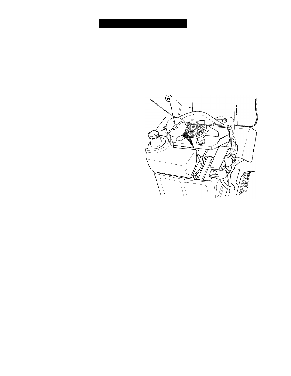
ALMACENAMIENTO
ALMACENAMIENTO
Antes de almacenar su unidad en la temporada baja, lea las
instrucciones de Mantenimiento y Almacenamiento en la sec
ción de Reglas de Seguridad, luego realice los siguientes
pasos:
« Desacople el PTO, ponga el freno de mano y quite la
llave.
* Verifique el nivel de todos los fluidos. Verifique todos los
elementos de mantenimiento.
* La vida de la batería se incrementará si la quita, y la
coloca en un lugar seco y fresco y la carga por completo
una vez al mes. Si deja la batería en la unidad,
desconecte el cable negativo.
Es importante evitar que se formen depósitos de goma en
las partes esenciales de la instalación de combustible como
el carburador, filtro de la gasolina, tubería del combustible y
el tanque de gasolina durante el almacenamiento. Además,
los combustibles mezclados con alcohol (llamados gasohol o
usando etanol o metanol) puede atraer humedad que lleva a
la separación y formación de ácidos durante el almace
namiento. El gas acídico puede dañar la instalación de com
bustible de un motor mientras está en almacenamiento.
Para evitar problemas con el motor, la instalación de com
bustible debe vaciarse antes del almacenamiento de 30 días
o más. Siga estas instrucciones;
1. Detenga el motor, quite la llave y permita que se enfríe el
motor.
2. Coloque un contenedor adecuado abajo del filtro de la
gasolina (A, Figura 39'} para atrapar el combustible der
ramado, y coloque un contenedor adecuado para sosten
er el contenido del tanque de gasolina junto a la unidad.
3. Usando pinzas de cierre, quite las abrazaderas de la
tubería del combustible entre el filtro de la gasolina (A) y
el tanque de gasolina.
4. Extienda las abrazaderas por el filtro de la gasolina sólo
lo suficiente para quitar la abrazadera del filtro.
5. Desconecte la tubería del combustible del filtro de la
gasolina.
6. Canalice la tubería del combustible a un contenedor ade
cuado, quite las pinzas de cierre y drene el tanque de
gasolina.
7. Conecte nuevamente el filtro de la gasolina y sujételo con
la abrazadera.
8. Arranque y corra la unidad hasta consumir todo el com
bustible.
Antes de arrancar la unidad después de estar almacenada:
* Verifique el nivel de todos ios fluidos. Verifique todos los
elementos de mantenimiento.
» Llene con combustible FRESCO.
« Después de arrancar, permita que el motor se caliente
antes de operar.
A ADVERTENCIA
Nunca almacene la unidad (con combustible) en una
estructura cerrada con poca ventilación. Los vapores
del combustible pueden viajar a una fuente de ignición
(como un horno, calentador de agua, etc.) y ocasionar
una explosión.
Los vapores del combustible también son tóxicos para
los humanos y animales.
Figura 39. Compartimiento del Motor
A. Filtro de la Gasolina
A
ADVERTENCIA
La gasolina es altamente inflamable y debe
manejarse con cuidado. Nunca llene el tanque
cuando el motor todavía está caliente por la
reciente operación. No permita que nadie se
acerque con llamas abiertas, cigarros o cerillos al
área. Evite llenar demasiado y quite lo derramado
con un trapo.
62
Page 63

DÍAGNOSTICQ
Si bien el cuidado normal y e¡ mantenimiento regular exten
derán la vida de su equipo, el uso prolongado o constante hará
que eventualmente se deba realizar un servicio para permitir
que continúe operando debidamente. La guía de diagnóstico
abajo enumera los problemas más comunes, sus causas y
remedios.
Si lo prefiere, todos estos procedimientos pueden ser ejecuta
dos para usted por un Centro de Partes y Reparaciones de
Sears. Vea la contraportada respecto a Información sobre el
Centro de Partes y Reparaciones de Sears.
Diagnóstico del Tractor
PROBLEMA CAUSA REMEDIO
El motor no rota
ni arranca.
El motor arranca
El freno de mano no está en PARK Ponga el freno de mano en PARK.
El interruptor PTO está en posición de ON. Colóquelo en posición de OFF.
Palancas de velocidad no están en posición de PARK..
El acelerador no está en posición de CHOKE. Mueva el acelerador a posición de CHOKE.
Llave no está por completo a la posición de START.
Sin combustible. Si el motor está caliente, permita que enfríe,
Motor ahogado. Mueva el control del acelerador de regreso a la
La gasolina está vieja o viciada.
Agua en el combustible.
Terminales de batería requieren una limpieza. Limpie las terminales de la batería
Batería descargada o baja. Recargue o reemplace.
Bujía(s) defectuosas, sucias o con entrehierro
incorrecto.
Cableado suelto o roto.
Solenoide o motor de arranque defectuosos.
Interruptor del ¡ntercierre de seguridad defectuoso. Reemplace. Contacte Partes y Reparaciones de Sears.
Filtro de aire obstruido Dé servicio al pre-limpiador y/o reemplace el ele
difícil o no fundona bien.
Acelerador en posición de CHOKE más de lo
necesario.
Bujía defectuosa, sucia o con entrehierro incorrecto.
^ADVERTENCIA
Para evitar lesiones graves, realice el
mantenimiento del tractor o la podadera sólo con
el motor apagado y el freno de mano en PARK.
Siempre quite la llave del encendido, desconecte
el cable de la bujía y sujételo lejos de la bujía
antes de empezar con el mantenimiento, para
evitar que el motor arranque accidentalmente.
Muévalas a la posición de PARK.
Gire la llave a la posición de START.
luego llene el tanque de gasolina.
posición de FULL para abrir el ahogador.
Drene el combustible y ponga combustible fresco.
Drene el combustible y ponga combustible fresco.
Limpie y ajuste a entrehierro o reemplace.
Verifique visualmente el cableado y reemplace cables
rotos 0 raídos. Apriete las conexiones sueltas.
Reemplace. Contacte Partes y Reparaciones de Sears.
mento del filtro de aire.
Ponga el acelerador en posición de FULL.
Limpie y ajuste a entrehierro o reemplace.
Motor golpetea. Nivel del aceite bajo. Verifique/agregue aceite según se requiera.
Uso de aceite de grado incorrecto. Vea "Cambiar el Aceite del Motor" en la Sección
de Mantenimiento.
Excesivo con
sumo de aceite.
El humo del
escape del
motor es negro.
Motor se calienta demasiado mientras opera. Limpie el abanico de enfriamiento del motor, la
rejilla sopladora y el limpiador de aire.
Uso de aceite de peso incorrecto. Vea "Cambiar el Aceite del Motor" en la Sección
de Mantenimiento.
Demasiado aceite en el cárter. Drene el aceite excedente.
Filtro de aire sucio. Reemplace el filtro de aire. Vea "Reemplazar el
Elemento del Filtro de Aire".
Control del ahogador en posición de cerrado. Abra el control del ahogador.
63
Page 64

El motor opera
pero el tractor
no avanza.
Las palancas de desembrague de la
transmisión en posición de EMPUJAR.
La banda de tracción se barre. Limpie 0 reemplace la banda según sea necesario.
La banda está rota.
Freno de mano no está desaccionado Contacte Partes y Reparaciones de Sears.
Mueva las palancas a la posición de DRIVE.
Reemplace banda. Contacte Partes y Reparaciones de Sears.
Banda de trac
Poleas 0 la banda con grasa o aceite. Limpie según se requiera.
ción se barre.
Reemplace banda. Contacte Partes y Reparaciones de Sears.
El freno de mano
La banda está estirada o desgastada.
El freno de mano está mal ajustado. Vea la Sección de Ajustes.
no se mantiene.
Tractor se direc-
Inflado inadecuado de las llantas. Vea la Sección de Mantenimiento.
ciona o maneja
con deficiencia.
Tractor estira
para un lado.
Acoplamiento de dirección está flojo. Verifique y apriete las conexiones sueltas.
Las perillas de ajuste de velocidad no
están ajustadas.
Vea AJUSTE DE BALANCEO DE VELOCIDAD
Diagnóstico de la Rodadora
PROBLEMA CAUSA REMEDIO
Es difícil ajustar la
altura de corte de
La rosca de la manivela para la altura de
corte está sucia o necesita lubricarse.
Limpie a conciencia y lubrique la manivela de altura
de corte con aceite.
la podadera.
Corte de la podado-
ra es desigual.
El corte de la
podadera es de
aspecto tosco.
Llantas del tractor indebidamente infladas.
Rodadora indebidamente nivelada.
La velocidad del motor es demasiado
lenta.
Velocidad demasiado alta. Disminuya la velocidad.
Vea la Sección de Mantenimiento.
Vea "Nivelado de la Podadora" en Servicio y Ajustes.
Ponga el acelerador en FULL cuando pode el
césped.
El motor se atasca
con facilidad con la
podadera embraga
da.
Vibración excesiva
de la podadera.
La banda de trac
ción de la podadora se barre o no
impulsa.
Las aspas están desafiladas. Afile 0 reemplace las aspas. Vea la Sección de
Mantenimiento.
Banda de tracción de podadera se barre
por que tiene aceite o está desgastada.
Las aspas no están debidamente afian
zadas al árbol de sujeción.
Velocidad del motor demasiado lenta. Ponga el acelerador en FULL.
Velocidad demasiado alta. Disminuya la velocidad.
La altura de corte está demasiado baja. Corte el césped alto con la altura máxima de corte
Lado inferior de cubierta de podadora sucio.
La tolva de descarga se atasca con las
hierbas cortadas.
Pernos de montaje de aspas están flojos. Apriete a 45-55 ft. Ibs. (61-75 N.m.).
Aspas, árboles de sujeción o poleas doblados.
Las aspas de la podadora están fuera de
equilibrio.
Banda instalada incorrectamente. Reinstale correctamente.
El resorte de la polea tensora está roto o
no está debidamente fijado.
Banda de tracción de podadora está rota. Reemplace la banda de tracción.
Embrague del PTO fuera de ajuste.
Limpie 0 reemplace la banda según sea necesario.
Vea "Verificar/Ajustar Aspas de Podadora" en la
Sección de Mantenimiento.
en la primera pasada.
Quite cubierta de la podadora y limpie lado inferior.
Corte el césped con la descarga apuntando hacia el
área anteriormente cortada.
Verifique y reemplace según sea necesario.
Reemplace o equilibre las aspas. Vea la Sección de
Mantenimiento.
Repare o reemplace según sea necesario.
Ajuste el embrague del PTO. Vea la Sección de Mantenimiento.
64
Page 65

Repair Parts
PTS-1
Page 66

Frame, Body & Seat Group (986460)
NOTE: Unless noted otherwise,
use the standard hardware torque
specification chart.
ZT 7000-107.277700
PTS-2
Page 67

Frame, Body & Seat Group (986460)
REF NO PART NO. QTY. DESCRIPTION
1 1726018SM 1 SEAT ASSEMBLY, wth Arm Rests (Includes Ref. No. 68)
2 1726305SM 1 DECK, Seat
3 1722293SM 4 CAPSCREW, Hex, Socket Head, 1/4-20 x 7/8, G5
4 1726369SM 1 PLATE, Pod Control
5 1673320SM 3 RIVET, Pop
6 1708504SM 1 SCREEN, Seat Deck
7 1960715SM 4 SCREW, Truss Head Torx Drive, 1/4-20 x 3/4
8 1920397SM 4 NUT, Hex Lock ESNA Light, 1/4-20
9 1960694SM 6 NUT, Hex Flange ESNA, 1/4-20
10 1716027SM 1 PLATE, Battery
11 1925003SM 6 CAPSCREW, Hex Washer Head Taptife, 1/4-20 x 1/2, G5
12 1715961SM 1 SUPPORT, Reservoir
13 1925205SM 2 CAPSCREW, Hex Head, 5/16-18 x 5/8, G5
14 1673796SM 1 SPACER, Powdered Metal
15 1931277SM 8 NUT, Hex Flange Whiz Lock, 5/16-18
16 1931317SM 2 CARRIAGE BOLT, 1/4-20 x 3/4
17 1715962ASM 1 SHROUD, Rear
18 1726417SM 1 DUCT, Air Inlet
19 1960518SM 2 NUT, Push, 1/4
20 1725982SM 1 SUPPORT, Seat Deck
21 1923341SM 1 CAPSCREW, Hex Head, 1/4-20 x 3/4, G5
22 1922127SM 1 CAPSCREW, Hex Head, 5/16-18 x 1-3/4, G5
23 1726390SM 2 BUMPER, Rubber
24 1921333SM 1 CAPSCREW, Hex Head, 5/16-18 x 1, G5
25 1708362ASM 1 BRACE, Tank
26 1714020SM 1 CAP, Fuel Tank
27 1726397SM 1 TANK, Fuel
28 1930600SM 1 CAPSCREW, Hex Washer Head Taptite, 5/16-18 x 1-1/2
29 1960606SM 2 LOCKWASHER, Pyramidal, Hex, 3/4
30 1710437SM 1 SPACER
31 1726400SM 1 BUSHING, Fuel Tank
32 1674792SM 1 ELBOW, with Screen, Gas Tank To Fuel Line
33 2860112SM 2 CLAMP, Hose, Wire Type E
34 1718678SM 1 HOSE, Fuei
35 1933988SM 2 NUT, Push
36 1930591 SM 6 CAPSCREW, Hex Flange Whiz Lock, 5/16-18 x 3/4
37 1728986SM 1 PAD, Footrest, R.H.
38 1728987SM 1 PAD, Footrest, L.H.
39 1729629SM 1 FRAME & SPINDLES ASSEMBLY (Includes Ref. Nos. 40, 41, 42, 43, 44 & 45)
40 1716065SM 1 ARM, Caster, L.H.
41 2834712SM 2 RING, E-Refaining
42 1919394SM 4 WASHER
43 1721682SM 4 BUSHING
44 2821133SM 2 FITTING, Lube
45 1716066SM 1 ARM, Caster, R.H.
46 1920328SM 1 CAPSCREW, Hex Head, 1/2-13 x 1-1/2, G5
47 1664847SM 2 SCREW, Hex Washer Head Taptite, 5/16-18 x 3/4
48 1726024ASM 1 BRACKET, Footrest Support
Footnotes
ZT 7000-107.277700
PTS-3
Page 68

Frame, Body & Seat Group (986460)
NOTE: Unless noted otherwise,
use the standard hardware torque
specification chart.
ZT 7000-107.277700
PTS-4
Page 69

Frame, Body & Seat Group (986460)
REF NO PART NO. QTY. DESCRIPTION
49 1960368SM 2 LUG NUT, Speed, 1/4-20
50 1930641SM 3 NUT, Hex Flange Whiz Lock, 1/4-20
51 1930644SM 1 NUT, Hex Flange Two-Way Lock, 1/2-13
52 1709235SM 1 SPACER
53 1716064ASM 1 HOOK & WASHER ASSEMBLY
54 1726025A 1 PANEL, Footrest
55 1726306SM 1 PAD, Footrest, Front
56 1726504SM 2 CAP, Hub
57 1725926SM 1 PANEL, Front
58 1704626SM 2 SPACER
59 1705249SM 2 SPACER
60 1705248SM 2 PIVOT, Hood
61 1704628SM 2 PIN, Quick
62 1960373SM 2 CAPSCREW, Hex Washer Head Taptite, 5/16-18 x 1
63 1935255SM 4 LUG NUT, Speed, 5/16-18
64 1960295SM 4 SCREW, Hex Flange Whiz Lock, 1/4-20 x 5/8
65 1726520SM 1 KNOB, Exterior Thread, 5/16-18 x 1
66 1725929ASM 1 SUPPORT, Seat
67 1716654SM 3 BOLT, Hex Shoulder, 5/16-18 3/4, G5
68 1687021 SM 1 ARM REST KIT, (LH. & R.H.)
ZT 7000-107.277700
Footnotes
PTS-5
Page 70

Engine Group (986461)
NOTE: Unless noted otherwise,
use the standard hardware torque
specification chart.
ZT 7000-107.277700
PTS -6
Page 71

Engine Group (986461)
REF NO PART NO. QTY. DESCRIPTION
1 1726398SM 1 CONTROL, Throttle
*
2
3 1726420SM 1 SEAL, Foam
4 1927187SM 4 CAPSCREW, Hex Washer Head Taptite, 3/8-16 x 1
5 1720463SM 1 KEY, Parallel
6 1719385SM 1 PULLEY
7 1686880SM 1 CLUTCH, Electric, OGURA
8 2832747SM 1 TIE, Self Locking
9 1708264SM 1 WASHER, Hex
10 1918199SM 1 LOCKWASHER, Spring
11 2860631SM 1 CAPSCREW, Hex Head, 7/16-20 x 3, G5
12 1726498SM 1 HOSE, Oil Drain
13 1713502SM 1 PIPE, Exhaust
14 1960748SM 1 CARRIAGE BOLT, 5/16-18 x 3-1/4, G5
15 1676183SM 1 CLAMP, Exhaust
16 1919326SM 4 WASHER, 5/16
17 1917372SM 2 NUT, Hex, 5/16-18
18 1935255SM 1 LUG NUT, Speed, 5/16-18
19 1708416SM 1 MUFFLER
20 1921333SM 1 CAPSCREW, Hex Head, 5/16-18 x 1, G5
21 1917356SM 2 LOCKWASHER, Spring
22 1713557ASM 1 SUPPORT, Muffler
23 1924856SM 3 CAPSCREW, Hex Washer Head Taptite, 5/16-18 x 1/2
24 1722621ASM 1 DUCT, Air, Bottom
25 1726539SM 1 SHIELD, Heat
26 1960720SM 4 SCREW, Hex Head, #10x1/2
27 1726634SM 1 SHIELD, Muffler, Oil Filter Access Panel
28 1726633SM 1 SHIELD, Muffler
1 ENGINE, 18HP, KOHLER
ZT 7000-107.277700
Footnotes
Note* See Engine Repair Parts.
PTS-7
Page 72

Carrier Group (986465)
NOTE: Unless noted otherwise,
use the standard hardware torque
specification chart.
ZT 7000-107.277700
PTS -8
Page 73

Carrier Group (986465)
REF NO PART NO. QTY. DESCRIPTION
1 1726470SM 1 V-BELT
2 1917372SM 1 NUT, Hex, 5/16-18
3 1917356SM 1 LOCKWASHER, Spring, 5/16
4 1924874SM 1 WASHER, 5/16
5 1715971ASM 1 ARM, Idler
6 1713588SM 1 SPACER, Powdered Metal
7 1928957SM 1 CAPSCREW, Hex Head, 3/8-16 x 2-3/4, G8
8 1924940SM 1 WASHER, 3/8
9 2154534SM 1 PULLEY, Idler
10 1667812SM 1 SPACER, Powered Metal
11 1726527SM 1 SPRING, Extension
12 1665699SM 3 SPACER
13 1916965SM 5 LOCKWASHER, Spring, 3/8
14 1916950SM 1 NUT, Hex, 3/8-16
15 1921719SM 1 CAPSCREW, Hex Head, 5/16-18x2-1/2, G5
16 1930644SM 1 NUT, Hex Flange Two-Way Lock, 1/2-13
17 1719725SM 1 SPACER
18 1924361SM 1 WASHER, 1/2
19 1921176SM 1 CAPSCREW, Hex Head, 1/2-13 x 1-1/4, G5
20 1718300SM 2 BUMPER, Weight, Cast Iron
21 1923701 SM 4 CAPSCREW, Hex Head, 3/8-16 x 2, G5
22 1726551 SM 1 FRAME ASSEMBLY, Transmission
23 1719682SM 1 CAPSCREW, Hex Head, 1/2-20 x 1-3/4, G8
24 1654565SM 2 WASHER, Spring, 1/2
25 1719683SM 1 SPACER
26 2860605SM 1 NUT, Hex Slotted, 1/2-20
27 1923500SM 1 PIN, Cotter, 1/8 X 1-1/2
28 1933896SM 2 NUT, Hex Lock
29 1716077SM 2 PIN, Yoke
30 1701996SM 2 SPRING, Extension
31 1716078SM 2 ROD, Brake, 10-24 x 1-1/8
32 1703805SM 2 RING, Klipring Extension for 1/2 Diameter Shaft
33 1715973SM 1 SHAFT & ARMS ASSEMBLY, Pivot
34 1725970SM 1 ROD, Clutch
35 1919326SM 2 WASHER, 5/16
36 1918447SM 2 PIN, Cotter
37 2159106SM 1 SPRING, Extension
ZT 7000-107.277700
Footnotes
PTS -9
Page 74
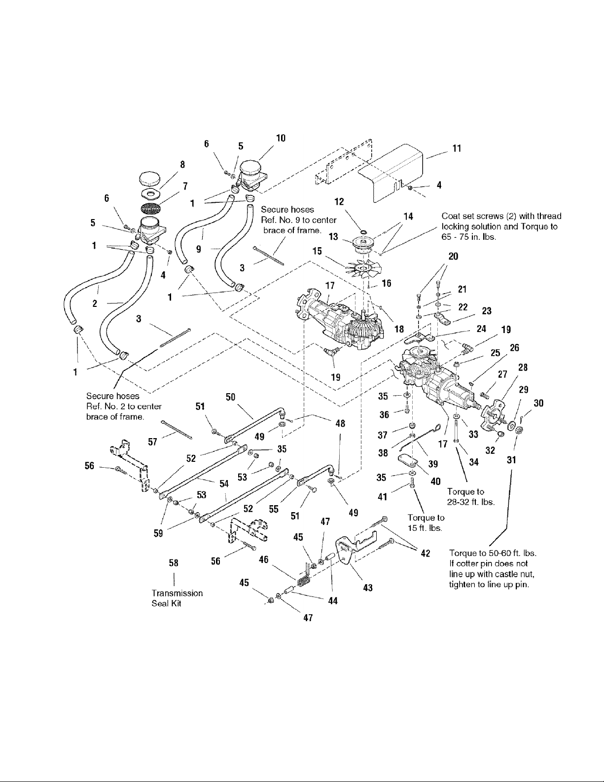
Transmission Group (986462)
NOTE: Unless noted otherwise,
use the standard hardware torque
specification chart.
ZT 7000-107.277700
PTS-10
Page 75

Transmission Group (986462)
ZT 7000-107.277700
REF NO PART NO. QTY. DESCRIPTION
1 2833098SM 8 CLAMP, Hose, Wire Type E
2 1719556SM 2 HOSE, Hydraulic
3 1701011SM 2 TIE, Self Locking
4 1960294SM 4 NUT, Hex, Whiz Lock, Flange, 1/4-20
5 1921319SM 4 WASHER, 1/4
6 1921959SM 4 CAPSCREW, Hex Head, 1/4-20 x 5/8, G5
7 1719912SM 2 FILTER, Reservoir
8 1723164SM 2 WASHER, Special
9 1719557SM 2 HOSE, Hydraulic
10 1702488SM 2 RESERVOIR, Hydro Expansion
11 1726494SM 1 COVER, Reservoir
12 2827731 SM 2 RING, Retaining
13 1719382SM 2 PULLEY
14 1960617SM 4 SET SCREW, Torx Head Cup Point, 1/4-28 x 1/4, G8
15 1719482SM 2 FAN, 10 Blades, 6" Plastic
16 1925003SM 8 CAPSCREW, Hex Washer Head Taptite, 1/4-20 x 5/8
17 1687181SM 2 TRANSMISSION ASSEMBLY (Includes Ref. Nos. 20, 21, 22, 23, 24, 26, 31,42, 43,
44, 45, 46 & 47)
18 2830672SM 2 KEY, Hi-Pro
19 1719560SM 2 FITTING, Hose Elbow, 3/8-18
20 1922234SM 4 CAPSCREW, Hex Head, 1/4-28 x 5/8, G5
21 1916964SM 4 LOCKWASHER, Spring, 1/4
22 1921319SM 4 WASHER, Flat, 1/4
23 1716044SM 2 ARM, Transmission Brake
24 1726500SM 2 ARM, Control
25 1930645SM 4 NUT, Hex Flange Two-Way Lock, 3/8-16
26 2805126SM 2 KEY, #15, 1/4 X 1
27 1663805SM 8 BOLT, Wheel Knurled, 7/16-20 x 1
28 1726351 SM 2 PLATE & HUB ASSEMBLY, Rear Wheel
29 1911386SM 2 WASHER, 3/4
30 1923500SM 2 PIN, Cotter
31 1716060SM 2 NUT, Hex Slotted, 3/4
32 2177725SM 8 NUT, Hex, 7/16-20, for Wheel Bolt
33 1924940SM 4 WASHER, 5/16
34 1922918SM 4 CAPSCREW, Hex Head, 3/8-16 x 3-1/4, G5
35 1919381SM 8 WASHER, 5/16
36 1960541 SM 4 CAPSCREW, Hex Washer Head Taptite, 5/16-18 x 3/4
37 1705590SM 2 SPACER
38 2170157SM 2 WASHER, Shakeproof, 1/2
39 1715957SM 2 ROD, Actuator
40 1715968SM 2 ACTUATOR, Tow Valve
41 1960373SM 2 CAPSCREW, Hex Washer Head Taptite, 5-16-18 x 1
42 1960273SM 4 CARRIAGE BOLT, 5/16-18 x 2-1/4
43 1726438ASM 2 SUPPORT, Neutral Return
44 1713588SM 4 SPACER
45 1919438SM 4 NUT, Flange ESNA, 5/16-18
46 1717165SM 2 SPRING, Torsion
47 1919381SM
4 WASHER, Flat, 5/16
Footnotes
Note* Seal Failures use Ref. No. 58 to order Seal Kit for Transmission Assembly 1726487.
PTS -11
Page 76

Transmission Group (986462)
NOTE: Unless noted otherwise,
use the standard hardware torque
specification chart.
ZT 7000-107.277700
PTS-12
Page 77

Transmission Group (986462)
REF NO PART NO. QTY. DESCRIPTION
49 1960027SM 2 WASHER, 1/2
50 1715958SM 1 LINK, Control Rear, R.H.
51 1931335SM 2 CARRIAGE BOLT, 5/16-18 x 1, G5
52 1703900SM 4 SPACER
53 1919438SM 4 NUT, Hex ESNA Light Lock, 5/16-18
54 1725945SM 2 ROD, Control
55 1715959SM 1 LINK, Control Rear, L.H.
56 1921333SM 2 CAPSCREW, Hex Head, 5/16-18 x 1, G5
57 1701011SM 1 TIE, Self Locking
58 1719442SM 1 * SEAL KIT, Transmission
59 1924874SM 2 WASHER, 5/16
ZT 7000-107.277700
Footnotes
Note* Seal Failures use Ref. No. 58 to order Seal Kit for Transmission Assembly 1726487.
PTS-13
Page 78
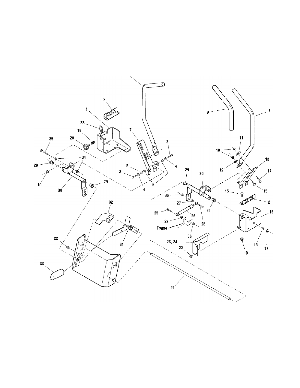
Controls Group (986463)
NOTE: Unless noted otherwise,
use the standard hardware torque
specification chart.
ZT 7000-107.277700
PTS-14
Page 79

Controls Group (986463)
REF NO PART NO. QTY. DESCRIPTION
1 1727049SM 1 BRACKET, Mounting, R.H.
2 1725978SM 2 BRACKET, Switch
3 1921977SM 4 CAPSCREW, Hex Head, 5/16-18x1-1/2, G5
4 1919326SM 4 WASHER, 5/16
5 1726445SM 2 WASHER, Flat Nylon, 1/2
6 1710437SM 4 SPACER
7 1725933SM 1 BRACKET, Tube Mount, R.H.
8 1725934ASM 2 TUBE, Control Wand
9 172641OSM 2 GRIP, Foam Handle Bar
10 1960686SM 14 NUT, Hex Flange ESNA, 5/16-18
11 1720452SM 2 CLAMP, Saddle
12 1919381SM 2 WASHER, 5/16
13 1726041SM 1 BRACKET, Tube Mount, L.H.
14 1931338SM 2 CARRIAGE BOLT, 5/16-18 x 1-3/4, G5
15 1931335SM 8 CARRIAGE BOLT, 5/16-18 x 1, G5
16 1727048SM 1 BRACKET, Mounting, L.H.
17 1703805SM 2 RING, Klipring
18 1960027SM 2 WASHER, 1/2
19 1701342SM 1 SPRING, Compression
20 1726520SM 1 KNOB, Extension, Threaded, 5/16-18 x 1
21 1725927SM 1 SHAFT, Cross
22 1925003SM 6 SCREW, Hex Washer Head Taptite, 1/4-20 x 5/8
23 1726497SM 1 COVER, Lower Handle, L.H.
24 1726496SM 1 COVER, Lower Handle, R.H.
25 1921221SM 4 CAPSCREW, Hex Head, 5/16-18 x 1-1/2, G5
26 1726308SM 2 SHOCK ABSORBER
27 1917372SM 4 NUT, Hex Jam, 5/16-18
28 1960717SM 1 NUT, Speed Lug Type, 5/16-18
29 1715025SM 4 BUSHING
30 1725938SM 2 PIVOT ASSEMBLY, Control
31 1725966SM 1 HANDLE ASSEMBLY, Brake
32 1726441 SM 1 SUPPORT, Switch
33 1722302SM 1 HANDLE
34 1931277SM 4 NUT, Hex Flange Whiz Lock, 5/16-18
35 1960273SM 2 CARRIABE BOLT, 5/16-18x2-1/4, G5
36 1919438SM 4 NUT, Hex Lock ESNA Light, 5/16-18
ZT 7000-107.277700
Footnotes
PTS-15
Page 80

Electrical Group (986464)
NOTE: Unless noted otherwise,
use the standard hardware torque
specification chart.
ZT 7000-107.277700
PTS-16
Page 81

Electrical Group (986464)
REF NO PART NO. QTY. DESCRIPTION
1 1732006SM 4 SWITCH, Push Button
2 1686734SM 1 SWITCH ASSEBMLY, Ignition (Includes Ref. Nos. 3, 4, 5 & 6)
3 1960547SM 1 LOCKWASHER, Internal Tooth, Ignition Switch
4 1717549SM 1 NUT, Hex Flange, 5/8-32, Ignition Switch
5 1717550SM 1 COVER, Ignition Switch
6 1717163SM 1 KEYS (Set of Two Keys)
7 1731184SM 1 METER, Hour Digifal, wifh Oil & Lube Alarms
8 172261 ISM 1 PLUG, HoIg
9 1722887SM 1 SWITCH, PTO Push/Pull
10 1701011SM 3 TIE, Self Locking
11 1732005SM 1 SWITCH, Push Butfon, Seat Switch
12 1667805SM 1 BRACE, Battery
13 1665872SM 1 STRAP, Black
14 1726376 1 BATTERY, 12 Volt, 6 Cell, 340 Amps
15 2823341SM 2 CAPSCREW, Hex Head, 1/4-20 x 3/4 G5
16 2821319SM 2 WASHER, 1/4
17 2816964SM 2 LOCKWASHER, Spring, 1/4
18 2816622SM 2 NUT, Hex, 1/4-20
19 1709086SM 1 BOOT, Insulator
20 1721830SM 1 CABLE, #6 X 25, 2 Ring Terminals
21 1703589SM 1 CABLE, #6 X 31,2 Ring Terminals
22 1666328SM 1 CABLE, #6 X 37-3/4, 2 Ring Terminals
23 1724588SM 3 COVER, Terminal
24 1665238SM 1 BREAKER, Circuit, 12 Volt, 20 Amps with Tab
25 1665237SM 1 WIRE, 12 GA
26 1686981 SM 1 SOLENOID, 4 Pole, 12 Volt DC
27 1925003SM 2 CAPSCREW, Hex Washer Head Taptite, 1/4-20 x 1/2, G5
28 2820426SM 2 LOCKWASHER, External Tooth
29 2820263SM 2 NUT, Hex, 5/16-24
30 1726016SM 1 HARNESS, Wiring
ZT 7000-107.277700
Footnotes
PTS-17
Page 82
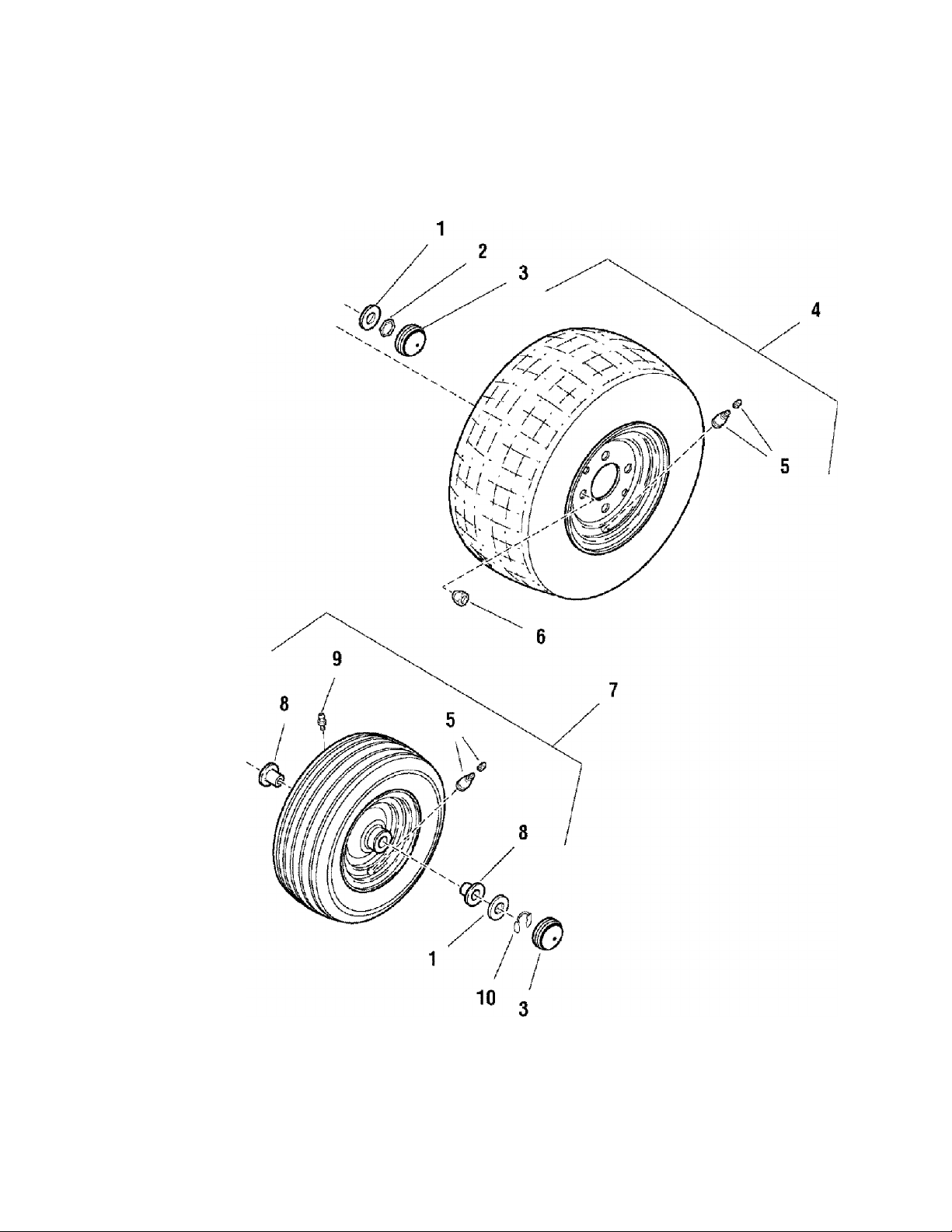
Wheels & Tires Group (W986467)
NOTE: Unless noted otherwise,
use the standard hardware torque
specification chart.
.. f A'v'f
'f 5
ZT 7000-107.277700
i
PTS-18
Page 83

Wheels & Tires Group (W986467)
REF NO PART NO. QTY. DESCRIPTION
1 2860202SM 4 WASHER, 3/4
2 1716099SM 2 NUT, Hex Lock PAL, 3/4-20
3 1722675SM 4 CAP, Hub
4 1726383SM 2 WHEEL & TIRE ASSEMBLY, Rear
5 2172353SM 2 VALVE STEM & CAP
6 2177725SM 8 NUT, Hex Lug, 7/16-20
7 1726382SM 2 WHEEL & TIRE ASSEMBLY, Front
8 1713167SM 4 BUSHING, Wheel
9 2812808SM 2 FITTING, Lube
10 1611710SM 2 RING, Klipring for 3/4 Shaft
ZT 7000-107.277700
Footnotes
PTS-19
Page 84
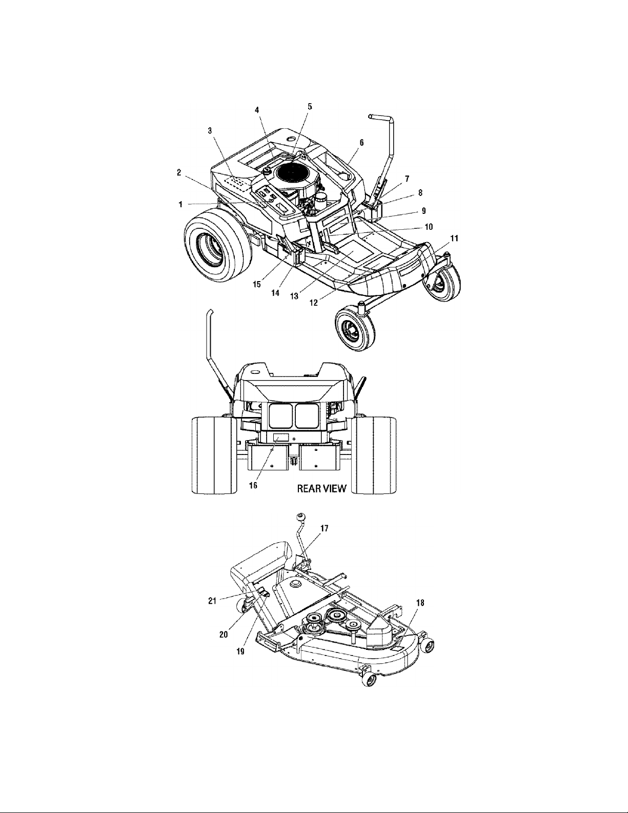
Decals Group (D986467)
NOTE: Unless noted otherwise,
use the standard hardware torque
specification chart.
ZT 7000-107.277700
PTS - 20
Page 85

Decals Group (D986467)
REF NO PART NO. QTY. DESCRIPTION
1 1726526SM 1 DECAL, Ignition Switch
2 1726523SM 1 DECAL, Hood Stripe, R.H.
3 1726525SM 1 DECAL, Sealed Hydraulic System
4 1726389SM 1 DECAL, Engine 18HP Kohler
5 1726631SM 1 DECAL, Do Not Remove Foam Seal
6 1726522SM 1 DECAL, Hood Stripe, L.H.
7 1725671 SM 1 DECAL, Speed Control, L.H.
8 1726524SM 1 DECAL, 18 Model ZT 7000
9 1726630SM 1 DECAL, ZT 7000
10 1726529SM 1 DECAL, Parking Brake
11 1726521 SM 1 DECAL, CRAFTSMAN
12 1726429SM 1 DECAL, Panel Upper, Operation
13 1726430SM 1 DECAL, Panel Lower, Warning/Danger & Icon Indicator
14 1726638SM 1 DECAL, Tracking
15 1725670SM 1 DECAL, Speed Control, R.H.
16 1715996SM 1 DECAL, Transmission Release Valve
17 1721197SM 1 DECAL, Height of Cut
18 1704276SM 1 DECAL, Danger (Do Not Put Hands/Feet in Mower)
*
19
20 1722790SM 1 DECAL, 50"
21 1704277SM 1 DECAL, Danger (Do Not Operate With Out Deflector)
1 DECAL, OPEI Certified (Not Serviced)
ZT 7000-107.277700
Footnotes
Note* Not a Service Part.
PTS - 21
Page 86
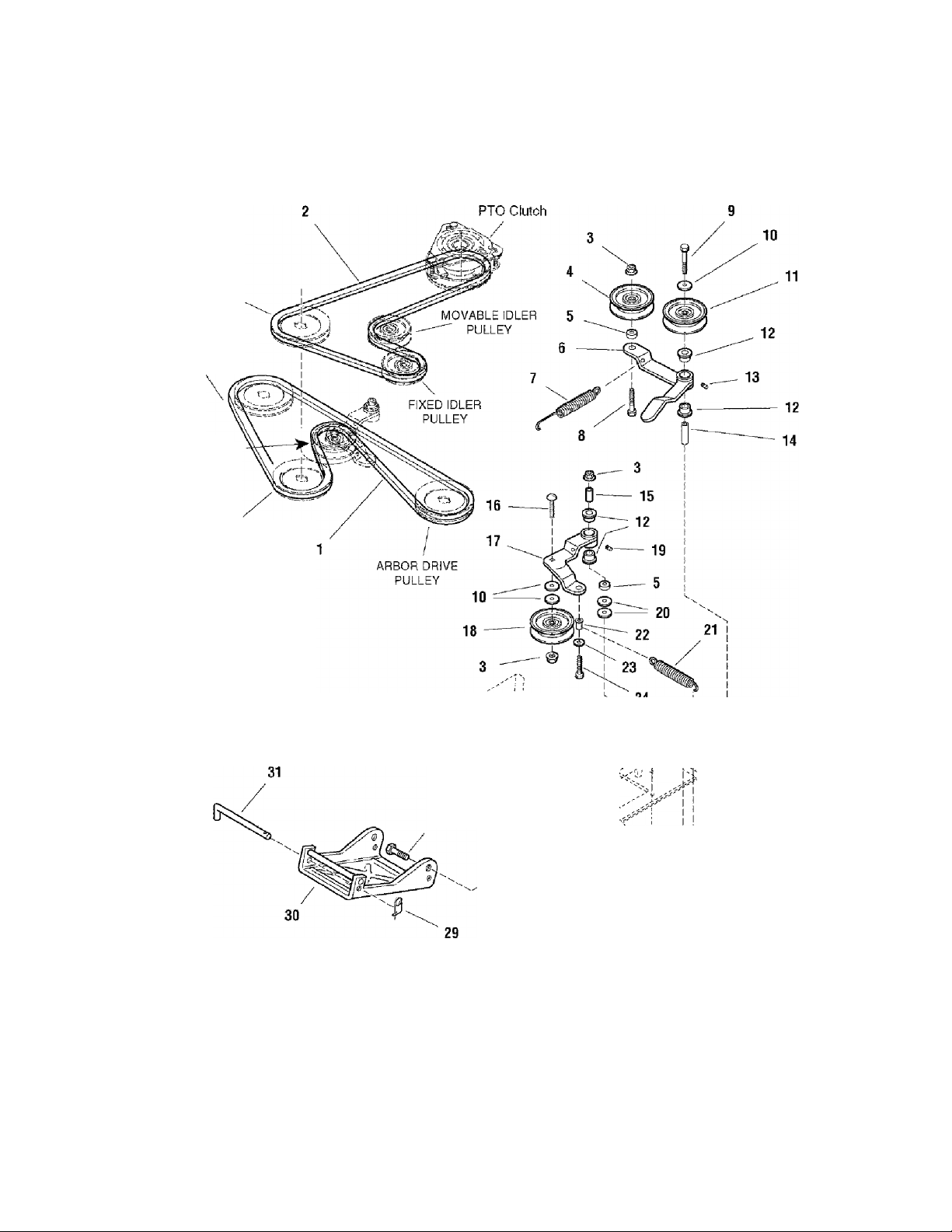
50" Mower Deck - Clutch & Support Group (986473)
NOTE: Unless noted otherwise,
use the standard hardware torque
specification chart.
ARBOR
PULLEY
ARBOR DRIVE
PULLEY
MOVABLE IDLER
PULLEY
ZT 7000-107.277700
ARBOR DRIVE
PULLEY
i V
\ \
■\ O'''" '*v"
; !
\ f' ‘^7'’"''* i
\\
1
21
26
'"-S V/ / L
/
20
u '\
1 ''
^ \ '
28
PTS - 22
25
Page 87

50" Mower Deck - Clutch & Support Group (986473)
REF NO PART NO. QTY. DESCRIPTION
1 1726472SM 1 V-BELT, Mower Drive
2 1726471SM 1 V-BELT, P.T.O.
3 1960339SM 4 NUT, Hex Flange, 3/8-16
4 2171247SM 1 PULLEY, Idler
5 166781 ISM 2 SPACER, Powdered Metal
6 1726814SM 1 LEVER & HANDLE ASSEMBLY (Includes Ref. Nos. 13 & 14)
7 1714062SM 1 SPRING, Extension
8 1923701 SM 1 CAPSCREW, Hex Head, 3/8-16 x 2, G5
9 1922918SM 1 CAPSCREW, 3/8-16x3-1/4
10 1924940SM 5 WASHER, 3/8
11 170651OSM 1 PULLEY, Idler
12 1676148SM 4 BUSHING
13 2812808SM 1 FITTING, Lube, 1/4-20 Tapered
14 1657242SM 1 SPACER, Hardened
15 1674669SM 1 SPACER, Hard Case
16 1960268SM 1 CARRIAGE BOLT, 3/8-16 x 1-1/4, G5
17 1718561SM 1 LEVER ASSEMBLY, Idler (Includes Ref. Nos. 12 & 20)
18 1724387SM 1 PULLEY, Idler
19 2821133SM 1 FITTING, Lube, 1/4 Drive
20 1924356SM 3 WASHER, 3/8
21 1656936SM 1 SPRING, Extension
22 1701159SM 1 SPACER
23 1921319SM 1 WASHER, 1/4
24 1933958SM 1 CAPSCREW, Hex Head, 1/4-20 x 1-1/6
25 1921972SM 1 CAPSCREW, Hex Head, 3/8-16 x 2-1/2, G5
26 1919439SM 2 NUT, Hex Lock ESNA Light, 3/8-16
27 1713791SM 2 SPACER, Powdered Metal
28 1922605SM 2 CAPSCREW, 3/8-16 X 1-1/4, G8
29 2176012SM 1 PIN, Retaining
30 172601OASM 1 HITCH & ROD ASSEMBLY
31 1726012SM 1 ROD, Hitch
ZT 7000-107.277700
Footnotes
PTS - 23
Page 88

50" Mower Deck - Height Adjustment Group (986471)
NOTE: Unless noted otherwise,
use the standard hardware torque
specification chart.
13 -—©
12
ZT 7000-107.277700
36
PTS - 24
38
Page 89

50" Mower Deck - Height Adjustment Group (986471)
REF NO PART NO. QTY. DESCRIPTION
1 1931202SM 2 CAPSCREW, Hex Washer Head Taptite, 5/16-18 x 1-1/4
2 1919381SM 1 WASHER, 5/16
3 1704114SM 1 ROD, Indicator Height of Cut
4 1726424ASM 1 PLATE & BRACKET ASSEMBLY, Gauge Wheel
5 1724009SM 1 TRUNNION, 1-1/4
6 1704097SM 1 WASHER, Detent
7 2816001SM 1 PIN, Spring
8 1960170SM 2 WASHER, 9/16
9 1715892SM 1 TRUNNION, 1-1/4
10 1704314SM 1 FITTING, Lube
11 1727681SM 1 CRANK, Height Adjustment
12 1714084SM 1 KNOB, Spinner, Soft
13 1960093SM 1 NUT, Push
14 1921977SM 2 CAPSCREW, Hex Head, 5/16-18x1-1/4, G5
15 1704116ASM 1 BRACKET, Height of Cut
16 1726409ASM 1 ARM, Rear
18 1931277SM 2 NUT, Hex, 5/16-18
19 1726007ASM 1 ARM ASSEMBLY, Roller Bar
20 192121OSM 2 CAPSCREW, Hex Head, 3/8-16 x 1, G5
21 1916965SM 2 LOCKWASHER, Spring, 3/8
22 1716010SM 2 SPACER, Support
23 1960655SM 1 CARRIAGE BOLT, 5/16-18 x 1-1/4, G5
24 1718136ASM 1 ARM, Rear Adjustable
25 1714879SM 1 CAM, Eccentric, Hex
26 1924874SM 1 WASHER, 5/16
27 2860643SM 1 NUT, Hex Flange Collar Lock , 5/16-18
28 1664847SM 6 CAPSCREW, Hex Washer Head Taptite, 5/16-18 x 3/4
29 1665374SM 3 STRAP, Arm Assembly
30 1960373SM 1 CAPSCREW, Hex Washer Head Taptite, 5/16-18 x 1
31 2118053SM 1 PIN, Round Head, Drilled, 3/8 x 2
32 1960074SM 1 PIN, Hair, 3/32
33 1960716SM 2 NUT, Hex Jam, 5/8-11
34 1924366SM 2 WASHER, 5/8
35 1706645ASM 1 TRUNNION
36 1930642SM 4 NUT, Hex Flange Toplock 1/4-20
37 1716020ASM 4 SHAFT & BAR ASSEMBLY, Roller Fixed Arm
38 1923341 SM 4 CAPSCREW, Hex Head, 1/4-20 x 3/4, G5
39 1714760SM 4 WHEEL, Roller
40 1960027SM 4 WASHER, 1/2
41 2158399SM 4 E-RING, Retaining Extenstion
42 1717152SM 1 ROD, Pitch
43 1918451SM 1 PIN, Cotter, 1/8 X 3/8
44 1709195SM 1 SPACER
ZT 7000-107.277700
Footnotes
PTS - 25
Page 90

50" Mower Deck - Housing & Arbor Group (986468)
NOTE: Unless noted otherwise,
use the standard hardware torque
specification chart.
ZT 7000-107.277700
PTS - 26
Page 91

50" Mower Deck - Housing & Arbor Group (986468)
REF NO PART NO. QTY. DESCRIPTION
1 1714419SM 3 NUT, Hex Flange Non-Locking, 9/16-18
2 1713675SM 6 WASHER, Belleville
3 1720387SM 1 PULLEY
4 1713158SM 1 HUB, Spacer, 2-13/32
5 1713098SM 3 PULLEY
6 1713533SM 1 HUB, 35/64
7 1713197SM 2 HUB, Serated, 35/64
8 1655729ASM 3 HOUSING, Arbor Top
9 2108202SM 3 BEARING, Ball
10 1715724SM 3 SPACER, Bearing Sleeve
11 1732544SM 3 SPACER, Tube
12 1707335SM 3 GASKET, Foam
13 1705897SM 3 BEARING, Ball
14 1713338ASM 3 HOUSING ASSEMBLY, Arbor Bottom, w/Lube Fitting
15 1704314SM 3 FITTING, Lube, 1/4 Drive
16 1720560ASM 1 COVER, Arbor
17 1664847SM 27 CAPSCREW, Hex Washer Head Taptite, 5/16-18 x 3/4, G5
18 1687037SM 1 HOUSING ASSEMBLY, Mower Deck
19 1713619SM 3 WASHER, Cup
20 1713195SM 2 SHAFT, Arbor with Extruded Washers (short)
21 1713196SM 3 SHIELD, Grass, Lower Arbor
22 1726453ASM 2 BLADE, Mower, Center & L.H.
23 1713089SM 3 WASHER, Hex
24 1656916SM 3 WASHER, Spring, 3/8
25 2823471SM 3 CAPSCREW, Hex Head, 7/16-14 x 1-1/4, G8
26 1726357ASM 1 BLADE, Mower, R.H. (High Lift)
27 1713612SM 1 SHAFT, Arbor with Extruded Washers (Long)
28 1931333SM 2 CARRIAGE BOLT, 5/16-18 x 3/4, G5
29 1724538ASM 1 BAFFLE, Blowout
30 1927557SM 2 NUT, Hex Flange Whiz Lock, 5/16-18
31 1931318SM 2 CARRIAGE BOLT, 1/4-20 x 7/8, G5
32 1703601 SM 1 COVER, Arbor
33 1960518SM 2 NUT, Push
34 1960353SM 2 WASHER, 1/4
35 1704873SM 1 CLAMP, Wire
36 1919326SM 1 WASHER, 5/16
37 1916964SM 2 LOCKWASHER, Spring, 1/4
38 1916622SM 2 NUT, Hex, 1/4-20
39 1723938SM 1 Sring, Torsion
40 1705115SM 1 PLUG, Button
41 1705449SM 1 DEFLECTOR, Discharge
42 1960633SM 1 CARRIAGE BOLT, 1/4-20 x 1-1/2, G5
43 1706709A 1 ROD, Deflector
44 1920397SM 1 NUT, Hex Lock ESNA Light, 1/4-20 NC-B3
ZT 7000-107.277700
Footnotes
PTS - 27
Page 92

Engine Parts
ZT 7000 - Model No. 107.277700
PTS - 28
Page 93

Engine Parts
REF NO. PART NO. QTY. DESCRIPTION REF NO. PART NO. QTY. DESCRIPTION
CRANKSHAFT - Group 1 19 12 393 01-S 1 Pump assembly, oil
1 12 014 57-S 1 Crankshaft (Includes 2) 20 12 032 03-S 1 Seal, oil (P.T.O. end)
2 25 139 27-S 1 Plug, cup 21 24 086 16-S 11 Screw, hex. flange
CRANKCASE - Group 2 22 24 086 17-S 1 Screw, hex. flange
1 12 032 03-S 1 Seal, crankshaft M8x1.25x45
2 1 Crankcase (Use: Short
3 12 445 02-S 1 Strap, lifting 1 25 351 01-S 2 Lifter, valve
4 M-839025-S 1 Screw, hex. flange 2 24 755 101-S 1 Kit, cylinder head (Includes
5 24 380 13-S 4 Pin, locating
6 12 010 31-S 1 Camshaft (Includes 7)
7 12 089 31-S 1 Spring, actuating 3 12 411 05-S 2 Rod, push
8 12 422 08-S (A.R.) Shim, camshaft - blue 4 12 041 10-S 1 Gasket, cylinder head
12 422 09-S (A.R.) Shim, camshaft - red 5 12 017 01-S 1 Valve, intake (Std.)
12 422 10-S
12 422 11-S
12 422 12-S
12 422 13-S
12 422 07-S 1 Shim, camshaft - white 10 M-640034-S 2 Screw, hex. flange
9 12 144 28-S 1 Shaft, balance M 6x1.0x34
10 12 874 07-S 1 Piston w/Ring Set (Std.) 11 12 089 34-S 2 Spring, valve
12 874 11 -S 1 Piston w/Ring Set (.08) 13 12 755 03-S 2 Kit, retainer
12 874 08-S 1 Piston w/Ring Set (.25) 14 12 468 05-S 1 Washer, plain 13/32“
12 874 09-S 1 Piston w/Ring Set (.50) 15 12 112 13-S 1 Spacer, head bolt exhaust
11 12 018 02-S 2 Retainer, piston pin port
12 12 108 07-S 1 Ring Set (Std. & .08) 16 20 086 02-S 5 Screw, hex. flange
12 108 08-S 1 Ring Set (.25) M10x1.5x81
12 108 09-S 1 Ring Set (.50) 17 25 237 14-S 2 Clamp, hose
13 12 067 11 -S 1 Connecting Rod (Std.) 18 12 326 18-S 1 Hose, breather
12 067 12-S 1 Connecting Rod (.25) 19 M-645016-S 5 Screw, hex. flange
14 12 380 01-S 1 Pin, governor regulating M6x1.0x16
15 12 043 05-S 1 Gear, governor 20 12 096 47-S 1 Cover, valve w/nippie
16 M-631005-S 1 Washer, plain 6 mm 21 M-545010-S 1 Screw, hex. flange
17 12 144 02-S 1 Shaft, governor gear M5x0.8x10
18 52 139 09-S 1 Plug, cup 22 66 018 04-S 1 Retainer, breather reed
19 12 755 64-S 1 Kit, governor cross shaft 23 12 402 02-S 1 Reed, breather
20 X-25-102-S 1 Washer, plain 1/4" NOT ILLUSTRATED
21 12 032 01-S 1 Seal, governor cross shaft 12 017 02-S 1 Valve, intake (.25)
22 M-631015-S 1 Washer, plain 6 mm 12 016 02-S 1 Valve, exhaust (.25)
23 12 154 05-S 1 Clip, hitch pin 12 041 01-S 2 Gasket, carburetor
OIL PAN/LUBRICATION - Group 3 12 041 03-S 1 Gasket, exhaust manifold
1 12 038 01-S 1 Dipstick (Includes 2, 3)
2 25 755 13-S 1 Kit, oil fill cap (Includes 3)
3 25 153 02-S 1 O-Ring
4 12 153 02-S 1 O-Ring, upper oil fill tube
5 12 123 04-S 1 Tube, oil fill
6 M-645025-S 1 Screw, hex. flange
7 12 153 01-S 1 O-Ring, lower oil fill tube
8 25 162 07-S 1 Screen, oil pickup
9 12 096 03-S 1 Cover, oil pickup screen
10 M-545016-S 1 Screw, hex. flange
11 12 199 56-S 1 Pan assembly, oil (Includes
12 25 462 09-S 1 Valve, oil pressure relief
14 25 139 57-S 1 Plug, sq. hd. solid 3/8"
15 52 050 02-S 1 Filter, oil
16 M-545016-S 3 Screw, hex. flange
17 12 096 34-S 1 Cover, oil pump
18 12 153 06-S 1 O-Rinq, oil pump cover
(A.R.)
(A.R.)
(A.R.)
(A.R.)
Block 12 522 69) HEAD/VALVE/BREATHER - Group 4
M8x1.25x25
Shim, camshaft - yellow 6 12 016 01-S 1 Valve, exhaust (Std.)
Shim, camshaft - green 7 12318 51-S 1 Cylinder Head
Shim, camshaft - gray 8 25 186 01-S 2 Arm, rocker
Shim, camshaft - black 9 12 599 03-S 2 Pivot, rocker arm
(Includes 11, 12) 12 12 173 01-S 2 Cap, valve spring
w/ciip (Includes 23)
12 041 02-S 1 Gasket, air cleaner base
M6x1.0x25
M5x0.8x16
12, 23-26)
M5x0.8x16
ZT 7000 - Mode! No. 107.277700
M8x1.25x45
3-16, carburetor gasket
(2),
PTS - 29
Page 94

Engine Parts
ZT 7000 - Model No. 107.277700
Page 95

Engine Parts
REF NO. PART NO. QTY. DESCRIPTION REF NO. PART NO. QTY. DESCRIPTION
IGNITION/ELECTRICAL - Group 5 4 12 227 19-S 1 Cap, drive end
1 12 086 14-S 1 Screw, hex. flange 5 12 170 05-S 1 Armature
2 12 468 03-S 1 Washer, plain 3/8" 7 12 227 13-S 1 Commutator, end cap
3 24 018 03-S 3 Retainer, grass screen 8 12211 01-S 2 Bolt, thru
4 24 162 03-S 1 Screen, grass
5 25 086 47-S 4 Bolt, shoulder FUEL SYSTEM - Group 8
6 12 157 06-S 1 Fan 1 M-641060-S 2 Nut, hex. flange M6x1.0
7 X-42-15-S 1 Key 2 M-629116-S 2 Stud M6x1.0x116
8 12 025 15-S 1 Flywheel 3 12 853 117-S 1 Kit, carburetor w/gaskets
9 41 403 09-S 1 Rectifier-regulator (Includes 4, 5 [qty. 1],
10 X-22-11-S 1 Washer, lock 1/4" Tie 12 454 03-S, and
11 12 086 42-S 2 Screw, tapping Terminal 25 452 20-S)
12 236602-S 1 Connector, rectifier-regula- 4 12 041 02-S 1 Gasket, air cleaner
13 12 154 06-S 2 Clip, rectifier-regulator 6 12 265 06-S 1 Deflector, heat
14 M-548025-S 2 Screw, hex. cap M5x0.8x25 7 25 050 07-S 1 Filter, fuel
15 237878-S 1 Kit, stator (Includes 8 25 237 14-S 6 Clamp, fuel line
16 41 155 02-S 1 Connector (5 contact) 10 12 559 02-S 1 Kit, fuel pump (Includes 11
17 M-545010-S 2 Screw, hex. flange 15)
18 X-728-1-S 2 Clip 12 25 153 04-S 1 O-Ring, fuel pump
19 12 132 02-S 1 Spark Plug 13 M-645020-S 2 Screw, hex. flange
20 12 584 04-S 1 Module, ignition M6x1.0x20
21 M-545020-S 2 Screw, hex. flange 14 25 294 09-S 1 Connector, straight hose
NOT ILLUSTRATED 16 12 123 19-S 1 Line, fuel
25 518 05-S 1 Lead, black, rectifier to
12 51801-S 1 Lead, white, ground to kill NOT ILLUSTRATED
24 518 12-S 1 Lead, black (6" -12 gauge w/gaskets
BLOWER HOUSING & BAFFLES Group 6 terminals)
1 M-545010-S 5 Screw, hex. flange 25 452 01-S 1 Terminal
2 24 468 10-S 1 Washer, plain 1/4" 25 454 03-S 3 Tie, wire
3 12 146 07-S 1 Plate, blower housing M-561010-S* 1 Screw, thread forming
4 M-645016-S 1 Screw, hex. flange M5x0.8x10
5 M-550010-S 1 Screw, hex. flange
6 24 096 05-S 1 Cover, pinion
7 12 027 55-S 1 Housing, blower
8 12 063 18-S 1 Baffle, intake side
9 M-541050-S 1 Nut, hex. flange M5x0.8
10 25 154 02-S 3 Clip, mounting
11 12 086 37-S 3 Screw
12 12 063 20-S 1 Baffle, cylinder head
13 12 063 19-S 1 Baffle, cylinder
NOT ILLUSTRATED
12 113 119-S 1 Decal, 18 HP
M10x1.5x46 6 12 221 01-S 1 Kit, brush
tor (3 contact) 5 12 041 01-S 2 Gasket, carburetor
Terminal 25 452 01-S) 9 25 353 14-S 1 Line, fuel 7"
M5x0.8x10 11 12 294 13-S 1 Connector, 90°
M5x0.8x20 15 12 353 01-S 1 Line, fuel 1-1/4"
17 M-545010-S 1 Screw, hex. flange
connector (5" -14 gauge M5x0.8x10
- uninsulated push on tab 18 12 154 01-S 1 Clamp, fuel line
terminals) 19 41 353 18-S 1 Line fuel 2-1/2"
(19" -18 gauge-fully 12 757 02-S 1 Kit, float
insulated push on tab and 12 757 03-S 1 Kit, carburetor repair
uninsulated push on tab 12 757 33-S 1 Kit, solenoid repair
terminals) 12 757 37-S 1 Kit, bowl replacement
- insulated grip barrel 12 518 24-S 1 Lead, red (18 gauge, - 20”
eyelet terminals) - insulated socket and
M5x0.8x10 12 454 03-S 1 Tie, wire
M6x1.0x16 X-22-11-S* 1 Washer, lock 1/4”
M5x0.8x10 *Used to attach carburetor ground lead to carburetor baffle.
ZT 7000 - Mode! No. 107.277700
uninsulated push on tab
STARTING SYSTEM - Group 7
1 M-839070-S 2 Screw, hex. flange
M8x1.25x70
2 12 098 22-S 1 Starter assembly (Includes
3-8)
3 12 755 53-S 1 Kit, drive
PTS - 31
Page 96
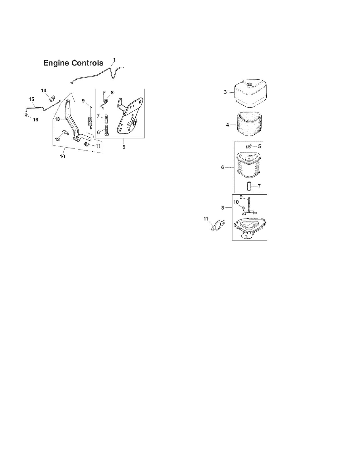
Engine Parts
ZT 7000 - Model No. 107.277700
Group 9
Group 10
Air intake/Filtration
2
Group 11
(o)—3
PTS - 32
Page 97

Engine P arts
REF NO. PART NO. QTY. DESCRIPTION
ENGINE CONTROLS - Group 9
1 12 079 11-S 1 Linkage, choke
2 12 237 01-S 1 Clamp, cable
3 M-545016-S 1 Screw, hex. flange
M5x0.8x16
4 M-664020-S 2 Screw, lobed socket
M6x1.0x20
5 12 536 01-S 1 Control, speed assembly
(Includes 6-8)
6 12 086 39-S 1 Screw, pan hd. w/loctite
patch
7 12 089 11-S 1 Spring, speed control
8 12 089 23-S 1 Spring, choke return
9 12 089 19-S 1 Spring, governor
10 12 755 83-S 1 Kit, governor lever
(Includes 11-13)
11 12 100 07-S 1 Nut, hex. flange M6x1.0
12 52 211 04-S 1 Screw, hex. flange
M6x1.0x25
13 12 090 28-S 1 Lever, governor
14 25 158 11-S 1 Bushing, linkage retaining
15 12 079 10-S 1 Linkage, throttle
16 25 158 08-S 1 Bushing, linkage retaining
AIR 1NTAKE/FILTRATION - Group 10
1 25 341 03-S 1 Knob, air cleaner cover
2 12 281 02-S 1 Duct, air
3 12 096 44-S 1 Cover, air cleaner
4 12 083 12-S 1 Element, precieaner
5 12 100 01-S 1 Wing Nut
6 12 083 10-S 1 Element, air cleaner
(Includes 5, 7, 8)
7 12 032 11-S 1 Seal
8 12 094 14-S 1 Base, air cleaner (Includes
10, 11)
9 12 072 04-S 1 Stud M6x1.0x79
10 12 086 01-S 2 Screw, #10 Hi-Lo thread
forming
11 12 041 02-S 1 Gasket, air cleaner
NOT ILLUSTRATED
12 113 04-S 1 Decal, air cleaner
ZT 7000 - Model No. 107.277700
EXHAUST - Group 11
1 12 068 55-S 1 Muffler
2 25 072 04-S 2 Stud M8x1.25x33
3 12 041 03-S 1 Gasket, exhaust manifold
4 X-25-78-S 1 Washer, plain 1/4”
5 M-545016-S 1 Screw, hex. flange
M5x0.8x16
6 M-841080-S 2 Nut, hex. flange M8x1.25
7 M-645016-S 2 Screw, hex. flange
M6x1.0x16
8 M-645025-S 2 Screw, hex. flange
M6x1.0x25
9 12 126 71-S 1 Bracket, muffler
NOT ILLUSTRATED
12 755 70-S 1 Kit, muffler guard (Includes
Screw (4) M-545010-S)
M-545010-S 4 Screw, hex. flange
M5x0.8x10
12112 20-S 2 Spacer
12 522 511 1 Short Block
12 755 93-S 1 Gasket Set
PTS - 33
Page 98

Hardware Identification & Torque Specifications
Common Hardware Types
Hex Head Capscrew
Carriage Bolt
Standard Hardware Sizing
When a washer or nut is identified as 1/2”, this is the
Nominal size, meaning the inside diameter is 1/2 inch; if a
second number is present it represent the threads per inch
When bolt or capscrew is identified as 1/2 -16 x 2”, this
means the Nominal size, or body diameter is 1/2 inch; the
second number represents the threads per inch (16 in this
example, and the final number is the body length of the
bolt or screw (in this example 2 inches long).
The guides and ruler furnished below are designed to
help you select the appropriate hardware and tools.
[, ■©! Washer
Lockwasher
Hex Nut
Inside
Diameter
Torque Specification Chart
FOR STANDARD MACHINE HARDWARE (Tolerance ± 20%)
Hardware
Grade
Size Of
Hardware
8-32 19 2.1 30 3.4 41 4.6
8-36 20 2.3 31 3.5 43 4.9
10-24 27 3.1 43 4.9 60 6.8
10-32 31 3.5 49 5.5 68 7.7
1/4-20 66 7.6 8 10.9 12 16.3
1/4-28 76 8.6 10 13.6 14 19.0
5/16-18 11 15.0 17 23.1 25 34.0
5/16-24 12 16.3 19 25.8 27 34.0
3/8-16 20 27.2 30 40.8 45 61.2
3/8-24 23 31.3 35 47.6 50 68.0
7/16-14 30 40.8 50 68.0 70 95.2
7/16-20 35 47.6 55 74.8 80 108.8
1/2-13 50 68.0 75 102.0 110 149.6
1/2-20 55 74.8 90 122.4 120 163.2
9/16-12 65 88.4 110 149.6 150 204.0
9/16-18 75 102.0 120 163.2 170 231.2
5/8-11 90 122.4 150 204.0 220 299.2
5/8-18 100 136 180 244.8 240 326.4
3/4-10 160 217.6 260 353.6 386 525.0
3/4-16 180 244.8 300 408.0 420 571.2
7/8-9 140 190.4 400 544.0 600 816.0
7/8-14 155 210.8 440 598.4 660 897.6
1-8 220 299.2 580 788.8 900 1,244.0
1-12 240 326.4 640 870.4 1,000 1,360.0
1. These torque values are to be used for all hardware
excluding: locknuts, self-tapping screws, thread forming
screws, sheet metal screws and socket head setscrews.
2. Recommended seating torque values for locknuts:
a. for prevailing torque locknuts - use 65% of grade 5
torques.
b. for flange whiziock nuts and screws - use 135% of
grade 5 torques.
3. Unless otherwise noted on assembly drawings, all torque
values must meet this specification.
f No^
i Marks!
SAE Grade 2
in/lbs
ft/lbs Nm.
G
SAE Grade 5
in/lbs
ft/lbs Nm.
NOTES
G
SAE Grade 8
In/lbs
ft/lbs Nm.
Wrench & Fastener Size Guide
1/4” Bolt or Nut
Wrench—7/16”
5/16”
Bolt or Nut
Wrench—1/2”
3/8” Bolt or Nut
Wrench—9/16”
PTS - 34
7/16” Bolt or Nut
Wrench (Bolt)—5/8”
Wrench (Nut)—11 /16”
1/2” Bolt or Nut
Wrench—3/4”
Page 99

Repair Protection Agreements
Acuerdo de Protección de Reparaciones
Congratulations on making a smart purchase. Your new
Craftsman® product is designed and manufactured for
years of dependabie operation. But iike all products, it
may require repair from time to time. That’s when having
a Repair Protection Agreement can save you money and
aggravation.
Purchase a Repair Protection Agreement now and pro
tect yourself from unexpected hassle and expense.
Here’s what’s included in the Agreement:
O' Expert service by our 12,000 professional repair
specialists
O' Unlimited service and no charge for parts and
labor on all covered repairs
O' Product replacement if your covered product can’t
be fixed
O' Discount of 10% from regular price of service and
service-related parts not covered by the agreement;
also, 10% off regular price of preventive maintenance
check
В Fast help by phone - phone support from a Sears
technician on products requiring in-home repair, plus
convenient repair scheduling.
Once you purchase the Agreement, a simple phone call
is all that it takes for you to schedule service. You can call
anytime day or night, or schedule a service appointment
online.
Sears has over 12,000 professional repair specialists,
who have access to over 4.5 million quality parts and
accessories. That’s the kind of professionalism you can
count on to help prolong the life of your new purchase for
years to come. Purchase your Repair Protection
Agreement today!
Some limitations and exclusions apply. For prices
and additional information call 1 -800-827-6655.
Sears Installation Service
For Sears professional installation of home appliances,
garage door openers, water heaters, and other major
home items, in the U.S.A. call 1-800-4-MY-HOME®
Felicidades por su compra inteligente. Su nuevo produc
to de Craftsman® fue diseñado y fabricado para años de
operación confiable. Pero como todos los productos, es
posible que cada cierto tiempo requiera de reparaciones.
Ahí es donde tener un Acuerdo de Protección de
Reparaciones puede ahorrarle dinero y contrariedades.
Compre un Acuerdo de Protección de Reparaciones
ahora y protéjase usted mismo de molestias y gastos
inesperados.
Aquí está lo que incluye el Acuerdo:
g. Servicio experto de nuestros 12,000 especialistas
profesionales en reparación
Servicio ilimitado y sin cargo por las partes y la
“ mano de obra en todas las reparaciones cubiertas
Reemplazo del producto si su producto cubierto no
“ puede ser arreglado
Descuento del 10% del precio regular de servicio y
“ partes relacionadas con el servicio no cubierto por el
acuerdo; además, de un 10% de descuento del pre
cio regular por revisiones de mantenimiento preventivo
„ Ayuda rápida por teléfono - soporte telefónico de
“ técnicos de Sears sobre productos que requieren
reparaciones a domicilio, además de programación
conveniente de reparación.
Una vez que compre el Acuerdo, una simple llamada
telefónica es lo único que se necesita para que le pro
gramen el servicio. Usted puede llamar a cualquier hora
del día o de la noche, o programar una cita de servicio
por Internet.
Sears cuenta con más de 12,000 especialistas profe
sionales en reparación, que tienen acceso a más de 4.5
millones partes y accesorios de calidad. Ese es el tipo
de profesionalismo con el que usted puede contar para
ayudarle a prolongar la vida de su nueva compra por
muchos años venideros. ¡Compre su Acuerdo de
Protección de Reparaciones hoy!
Aplican algunas limitantes y exclusiones. Para
obtener información sobre el precio e información
adicional llame al 1 -800-827-6655.
Servicio de Instalación de Sears
Para obtener información sobre la instalación profesional
de Sears para electrodomésticos, abridores para
cocheras, calentadores de agua y otros artículos
grandes, en los Estados Unidos llame a 1-800-4-MY-HOME®
Page 100

ït i^oiiliorou
Your Home
For repair-in your home-of all major brand appliances,
lawn and garden equipment, or heating and cooling systems,
n© matter who made it, n© matter who sold it!
For the replacement parts, accessories and
owner’s manuals that you need to do-it-yourself.
For Sears professional installation of home appliances
and items like garage door openers and water heaters.
1 “800"4"-MY"HOiViE® (1-800-469-4663)
Call anytime, day or night (U.S.A. and Canada)
www.sears.com www.sears.ca
Our Home
For repair of carry-in Items like vacuums, lawn equipment,
and electronics, call or go on-line for the location of your nearest
Sears Parts & Repair Center.
1 -800-488-1222
Call anytime, day or night (U.S.A. only)
www.sears.com
To purchase a protection agreement (U.S.A.)
or maintenance agreement (Canada) on a product serviced by Sears:
1-800-827-6655 (U.S.A.) 1-800-361-6665 (Canada)
Para pedir servicio de reparación
a domicilio, y para ordenar piezas:
1-888-SU-HOGAR"“
(1 -888-784-6427)
Au Canada pour service en français:
1-800-LE-FOYER“"
(1-800-533-6937)
www.sears.ca
® Registered Trademark /™ Trademark / Service Mark of Sears, Roebuck and Co.
® Marca Registrada / ™ Marca de Fábrica / Marca de Servicio de Sears, Roebuck and Co.
Marque de commerce / Marque déposée de Sears, Roebuck and Co. ) Sears, Roebuck and Co.
 Loading...