

Page 1

Operator's Manual
®
CTX Ga en Tractor
Model No.
107.250070 (30 Gross HP Briggs & Stratton with 54" Mower)
For answers to your questions about this
product, call Sears Craftsman Help Line
1=800=659-5917.
Sears Brands Management Corporation, Hoffman Estates, IL 60179 U.S.A.
Visit our Craftsman website: www.craftsman.com
1753804
Revision -
Page 2

Page 3
FrontCover................................................................................................................. 1
Operator Safety .......................................................................................................... 4
Features and Controls ............................................................................................. 10
Operation .................................................................................................................. 14
Safety Interlock System Tests ................................................................................. 14
Maintenance ............................................................................................................. 19
Troubleshooting ....................................................................................................... 30
Specifications ........................................................................................................... 32
Warranty .................................................................................................................... 33
Repair Protection Agreement .................................................................................. 34
Service Parts....................................................................................................... PTS-1
Thank you for purchasing this quality-built CRAFTSMAN mower. We're pleased that you've placed your confidence
in the CRAFTSMAN brand. When operated and maintained according to the instructions in this manual, your
CRAFTSMAN product will provide many years of dependable service.
This manual contains safety information to make you aware of the hazards and risks associated with mowers and
how to avoid them. This product and its approved attachments/accessories are designed and intended only for lawn
work or snow removal and are not intended for any other purpose. It is important that you read and understand these
instructions thoroughly before attempting to start or operate this equipment. Save these original instructions for
future reference.
Where to Find Us
You never have to look far to find support and service for your CRAFTSMAN mower. There are authorized service
dealers in North America who provide quality service. You can contact Customer Service by phone at (800) 659-5917,
or locate a dealer on the Internet at www.craftsman.com.
Mower
Model Number
Serial Number
Engine
Model Type Trim
Date Code
Date Purchased
3
Page 4

Congratulations on purchasing a superior-quality piece of lawn and
garden equipment. Our products are designed and manufactured to
meet or exceed all industry standards for safety.
Power equipment is only as safe as the operator, if it is misused, or
not properly maintained, it can be dangerous! Remember, you are
responsible for your safety and that of those around you.
Use common sense, and think through what you are doing, if you are
not sure that the task you are about to perform can be safely done
with the equipment you have chosen, ask a professional: contact
your local authorized dealer.
Readthe Manual
The operator's manual contains important safety information you
need to be aware of BEFORE you operate your unit as well as
DURING operation.
Safe operating techniques, an explanation of the product's features
and controls, and maintenance information is included to help you get
the most out of your equipment investment.
Be sure to completely read the Safety Rules and Information found on
the following pages. Also completely read the Operation section.
OperatingSafety
Children
Tragic accidents can occur with children. Do not allow them
anywhere near the area of operation. Children are often
attracted to the unit and mowing activity. Never assume that
children will remain where you last saw them. If there is a
risk that children may enter the area where you are mowing,
have another responsible adult watch them.
DO NOT GIVE CHILDREN RIDES ON THIS UNIT! This
encourages them to come near the unit in the future while it
is running, and they could be seriously hurt. They may then
approach the unit for a ride when you are not expecting it,
and you may run over them.
Reverse
Do not mow in reverse unless
absolutely necessary. Always look
down and behind before and while
traveling in reverse
even with the mower
blades disengaged.
Page 5
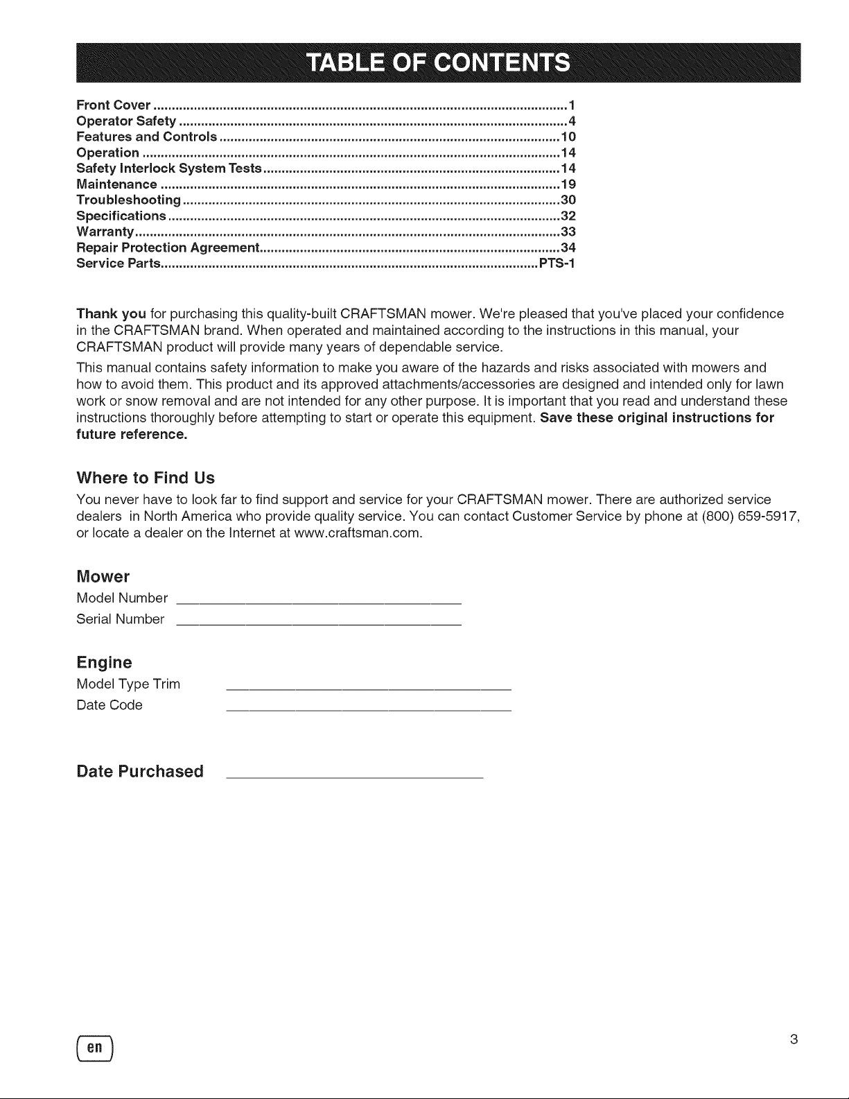
SlopeOperation
You could be seriously injured or even killed if you use this unit on too
steep an incline. Using the unit on a slope that is too steep or where you
don't have adequate traction can cause you to lose control or roll over.
A good rule of thumb is to not operate on any slope you cannot back up
(in 2-wheel drive mode). You should not operate on inclines with a slope
greater than a 3.5 foot rise over a 20 foot length. Always drive up and
down slopes: never cross the face.
3.5ft
20.0 ft (6,0 m)
Also note that the surface you are driving on can greatly impact stability
and control. Wet grass or icy pavement can seriously affect your ability to
control the unit.
If you feel unsure about operating the unit on an incline, don't do it. It's
not worth the risk.
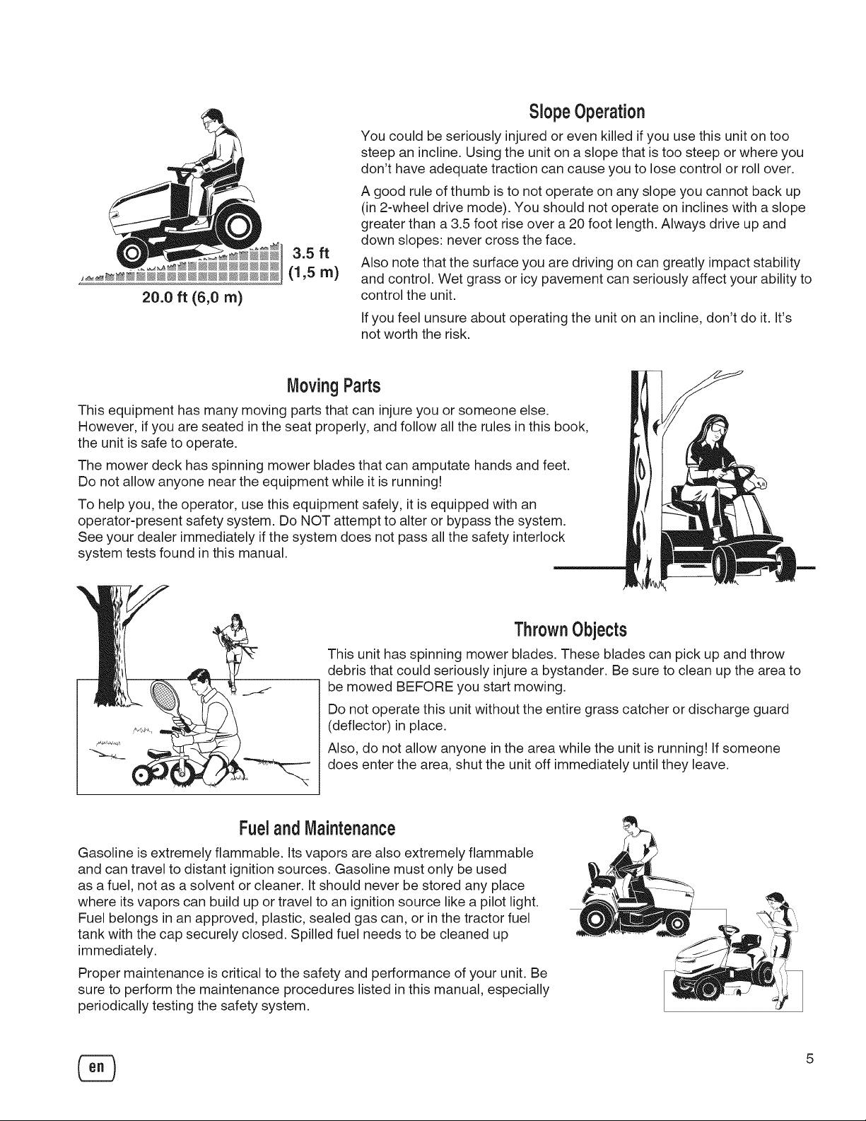
MovingParts
This equipment has many moving parts that can injure you or someone else.
However, if you are seated in the seat properly, and follow all the rules in this book,
the unit is safe to operate.
The mower deck has spinning mower blades that can amputate hands and feet.
Do not allow anyone near the equipment while it is running!
To help you, the operator, use this equipment safely, it is equipped with an
operator-present safety system. Do NOT attempt to alter or bypass the system.
See your dealer immediately if the system does not pass all the safety interlock
system tests found in this manual.
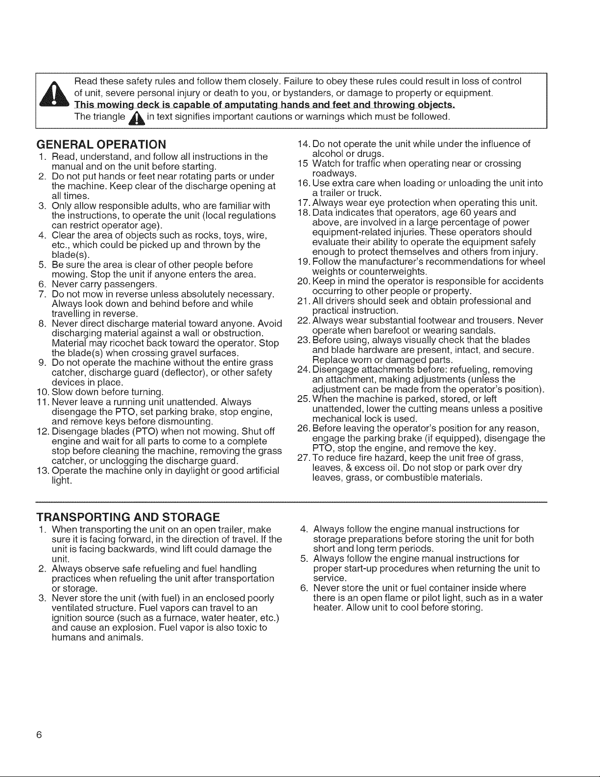
ThrownObjects
This unit has spinning mower blades. These blades can pick up and throw
debris that could seriously injure a bystander. Be sure to clean up the area to
be mowed BEFORE you start mowing.
Do not operate this unit without the entire grass catcher or discharge guard
(deflector) in place.
Also, do not allow anyone inthe area while the unit is running! ifsomeone
does enter the area, shut the unit off immediately until they leave.
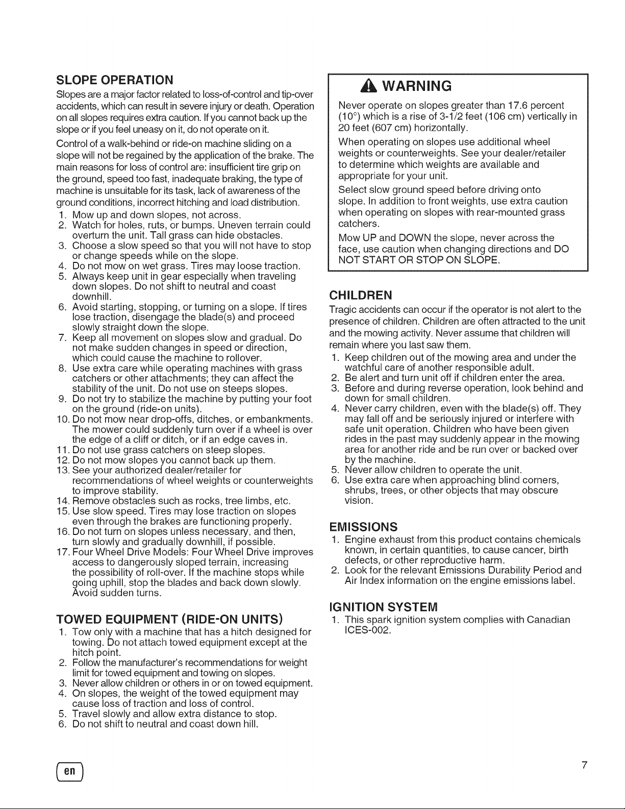
Fueland Maintenance
Gasoline is extremely flammable. Its vapors are also extremely flammable
and can travel to distant ignition sources. Gasoline must only be used
as a fuel, not as a solvent or cleaner, it should never be stored any place
where its vapors can build up or travel to an ignition source like a pilot light.
Fuel belongs in an approved, plastic, sealed gas can, or in the tractor fuel
tank with the cap securely closed. Spilled fuel needs to be cleaned up
immediately.
Proper maintenance is critical to the safety and performance of your unit. Be
sure to perform the maintenance procedures listed in this manual, especially
periodically testing the safety system.
5
Page 6
Readthesesafetyrulesandfollowthemclosely.Failuretoobeytheserulescouldresultinlossofcontrol
ofunit,severepersonalinjuryordeathtoyou,orbystanders,ordamagetopropertyorequipment.
This mowing deck is capable of amputating hands and feet and throwing objects.
The triangle _ in text signifies important cautions or warnings which must be followed.
GENERAL OPERATION
1. Read, understand, and follow all instructions in the
manual and on the unit before starting.
2. Do not put hands or feet near rotating parts or under
the machine. Keep clear of the discharge opening at
all times.
3. Only allow responsible adults, who are familiar with
the instructions, to operate the unit (local regulations
can restrict operator age).
4. Clear the area of objects such as rocks, toys, wire,
etc., which could be picked up and thrown by the
blade(s).
5. Be sure the area is clear of other people before
mowing. Stop the unit if anyone enters the area.
6. Never carry passengers.
7. Do not mow in reverse unless absolutely necessary.
Always look down and behind before and while
travelling in reverse.
8. Never direct discharge material toward anyone. Avoid
discharging material against a wall or obstruction.
Material may ricochet back toward the operator. Stop
the blade(s) when crossing gravel surfaces.
9. Do not operate the machine without the entire grass
catcher, discharge guard (deflector), or other safety
devices in place.
10. Slow down before turning.
11. Never leave a running unit unattended. Always
disengage the PTO, set parking brake, stop engine,
and remove keys before dismounting.
12. Disengage blades (PTO) when not mowing. Shut off
engine and wait for all parts to come to a complete
stop before cleaning the machine, removing the grass
catcher, or unclogging the discharge guard.
13. Operate the machine only in daylight or good artificial
light.
14. Do not operate the unit while under the influence of
alcohol or drugs.
15 Watch for traffic when operating near or crossing
roadways.
16. Use extra care when loading or unloading the unit into
a trailer or truck.
17.Always wear eye protection when operating this unit.
18. Data indicates that operators, age 60 years and
above, are involved in a large percentage of power
equipment-related injuries. These operators should
evaluate their ability to operate the equipment safely
enough to protect themselves and others from injury.
19. Follow the manufacturer's recommendations for wheel
weights or counterweights.
20. Keep in mind the operator is responsible for accidents
occurring to other people or property.
21. All drivers should seek and obtain professional and
practical instruction.
22. Always wear substantial footwear and trousers. Never
operate when barefoot or wearing sandals.
23. Before using, always visually check that the blades
and blade hardware are present, intact, and secure.
Replace worn or damaged parts.
24. Disengage attachments before: refueling, removing
an attachment, making adjustments (unless the
adjustment can be made from the operator's position).
25. When the machine is parked, stored, or left
unattended, lower the cutting means unless a positive
mechanical lock is used.
26. Before leaving the operator's position for any reason,
engage the parking brake (if equipped), disengage the
PTO, stop the engine, and remove the key.
27. To reduce fire hazard, keep the unit free of grass,
leaves, & excess oil. Do not stop or park over dry
leaves, grass, or combustible materials.
TRANSPORTING AND STORAGE
1. When transporting the unit on an open trailer, make
sure it is facing forward, in the direction of travel. If the
unit is facing backwards, wind lift could damage the
unit.
2. Always observe safe refueling and fuel handling
practices when refueling the unit after transportation
or storage.
3. Never store the unit (with fuel) in an enclosed poorly
ventilated structure. Fuel vapors can travel to an
ignition source (such as a furnace, water heater, etc.)
and cause an explosion. Fuel vapor is also toxic to
humans and animals.
4. Always follow the engine manual instructions for
storage preparations before storing the unit for both
short and long term periods.
5. Always follow the engine manual instructions for
proper start-up procedures when returning the unit to
service.
6. Never store the unit or fuel container inside where
there is an open flame or pilot light, such as in a water
heater. Allow unit to cool before storing.
Page 7
SLOPE OPERATION
Slopes are a major factor related to loss-of-control and tip-over
accidents, which can result insevere injury or death. Operation
on all slopes requires extra caution. If you cannot back up the
slope or if you feel uneasy on it, do not operate on it.
Control of a walk-behind or ride-on machine sliding on a
slope will not be regained by the application of the brake. The
main reasons for loss ofcontrol are: insufficient tire grip on
the ground, speed too fast, inadequate braking, the type of
machine is unsuitable for its task, lack of awareness of the
ground conditions, incorrect hitching and load distribution.
1. Mow up and down slopes, not across.
2. Watch for holes, ruts, or bumps. Uneven terrain could
overturn the unit. Tall grass can hide obstacles.
3. Choose a slow speed so that you will not have to stop
or change speeds while on the slope.
4. Do not mow on wet grass. Tires may loose traction.
5. Always keep unit in gear especially when traveling
down slopes. Do not shift to neutral and coast
downhill.
6. Avoid starting, stopping, or turning on a slope. If tires
lose traction, disengage the blade(s) and proceed
slowly straight down the slope.
7. Keep all movement on slopes slow and gradual. Do
not make sudden changes in speed or direction,
which could cause the machine to rollover.
8. Use extra care while operating machines with grass
catchers or other attachments; they can affect the
stability of the unit. Do not use on steeps slopes.
9. Do not try to stabilize the machine by putting your foot
on the ground (ride-on units).
10. Do not mow near drop-offs, ditches, or embankments.
The mower could suddenly turn over if a wheel is over
the edge of a cliff or ditch, or if an edge caves in.
11. Do not use grass catchers on steep slopes.
12. Do not mow slopes you cannot back up them.
13. See your authorized dealer/retailer for
recommendations of wheel weights or counterweights
to improve stability.
14. Remove obstacles such as rocks, tree limbs, etc.
15. Use slow speed. Tires may lose traction on slopes
even through the brakes are functioning properly.
16. Do not turn on slopes unless necessary, and then,
turn slowly and gradually downhill, if possible.
17. Four Wheel Drive Models: Four Wheel Drive improves
access to dangerously sloped terrain, increasing
the possibility of roll-over. If the machine stops while
going uphill, stop the blades and back down slowly.
Avoid sudden turns.
TOWED EQUIPMENT (RIDE-ON UNITS)
1. Tow only with a machine that has a hitch designed for
towing. Do not attach towed equipment except at the
hitch point.
2. Follow the manufacturer's recommendations for weight
limit for towed equipment and towing on slopes.
3. Never allow children or others in or on towed equipment.
4. On slopes, the weight of the towed equipment may
cause loss of traction and loss of control.
5. Travel slowly and allow extra distance to stop.
6. Do not shift to neutral and coast down hill.
WARNING
Never operate on slopes greater than 17.6 percent
(10 °) which is a rise of 3-1/2 feet (106 cm) vertically in
20 feet (607 cm) horizontally.
When operating on slopes use additional wheel
weights or counterweights. See your dealer/retailer
to determine which weights are available and
appropriate for your unit.
Select slow ground speed before driving onto
slope. In addition to front weights, use extra caution
when operating on slopes with rear-mounted grass
catchers.
Mow UP and DOWN the slope, never across the
face, use caution when changing directions and DO
NOT START OR STOP ON SLOPE.
CHILDREN
Tragic accidents can occur if the operator is not alert to the
presence of children. Children are often attracted to the unit
and the mowing activity. Never assume that children will
remain where you last saw them.
1. Keep children out of the mowing area and under the
watchful care of another responsible adult.
2. Be alert and turn unit off if children enter the area.
3. Before and during reverse operation, look behind and
down for small children.
4. Never carry children, even with the blade(s) off. They
may fall off and be seriously injured or interfere with
safe unit operation. Children who have been given
rides in the past may suddenly appear in the mowing
area for another ride and be run over or backed over
by the machine.
5. Never allow children to operate the unit.
6. Use extra care when approaching blind corners,
shrubs, trees, or other objects that may obscure
vision.
EMISSIONS
1. Engine exhaust from this product contains chemicals
known, in certain quantities, to cause cancer, birth
defects, or other reproductive harm.
2. Look for the relevant Emissions Durability Period and
Air Index information on the engine emissions label.
iGNITiON SYSTEM
1. This spark ignition system complies with Canadian
ICES-002.
7
Page 8
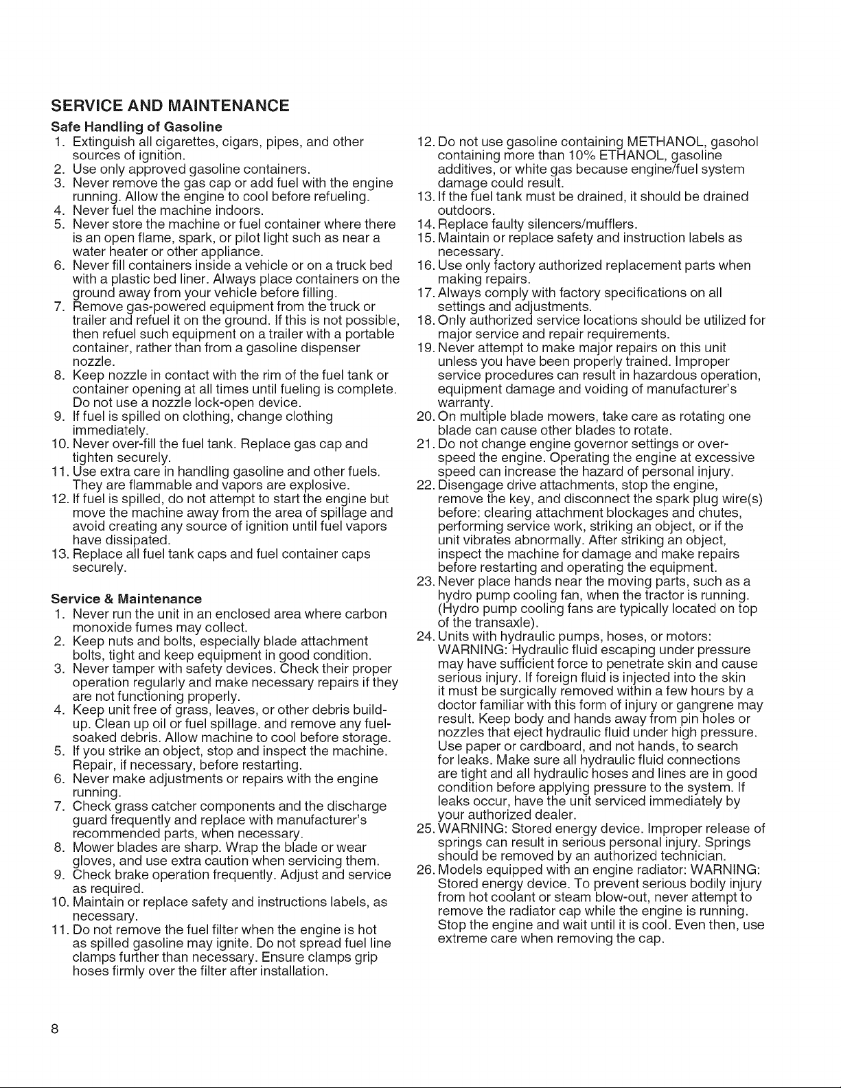
SERVICE AND MAINTENANCE
Safe Handling of Gasoline
1. Extinguish all cigarettes, cigars, pipes, and other
sources of ignition.
2. Use only approved gasoline containers.
3. Never remove the gas cap or add fuel with the engine
running. Allow the engine to cool before refueling.
4. Never fuel the machine indoors.
5. Never store the machine or fuel container where there
is an open flame, spark, or pilot light such as near a
water heater or other appliance.
6. Never fill containers inside a vehicle or on a truck bed
with a plastic bed liner. Always place containers on the
ground away from your vehicle before filling.
7. Remove gas-powered equipment from the truck or
trailer and refuel it on the ground. Ifthis is not possible,
then refuel such equipment on a trailer with a portable
container, rather than from a gasoline dispenser
nozzle.
8. Keep nozzle in contact with the rim of the fuel tank or
container opening at all times until fueling is complete.
Do not use a nozzle lock-open device.
9. Iffuel is spilled on clothing, change clothing
immediately.
10. Never over-fill the fuel tank. Replace gas cap and
tighten securely.
11. Use extra care in handling gasoline and other fuels.
They are flammable and vapors are explosive.
12. If fuel is spilled, do not attempt to start the engine but
move the machine away from the area of spillage and
avoid creating any source of ignition until fuel vapors
have dissipated.
13. Replace all fuel tank caps and fuel container caps
securely.
Service & Maintenance
1. Never run the unit in an enclosed area where carbon
monoxide fumes may collect.
2. Keep nuts and bolts, especially blade attachment
bolts, tight and keep equipment in good condition.
3. Never tamper with safety devices. Check their proper
operation regularly and make necessary repairs if they
are not functioning properly.
4. Keep unit free of grass, leaves, or other debris build-
up. Clean up oil or fuel spillage, and remove any fuel-
soaked debris. Allow machine to cool before storage.
5. Ifyou strike an object, stop and inspect the machine.
Repair, if necessary, before restarting.
6. Never make adjustments or repairs with the engine
running.
7. Check grass catcher components and the discharge
guard frequently and replace with manufacturer's
recommended parts, when necessary.
8. Mower blades are sharp. Wrap the blade or wear
gloves, and use extra caution when servicing them.
9. Check brake operation frequently. Adjust and service
as required.
10. Maintain or replace safety and instructions labels, as
necessary.
11. Do not remove the fuel filter when the engine is hot
as spilled gasoline may ignite. Do not spread fuel line
clamps further than necessary. Ensure clamps grip
hoses firmly over the filter after installation.
12. Do not use gasoline containing METHANOL, gasohol
containing more than 10% ETHANOL, gasoline
additives, or white gas because engine/fuel system
damage could result.
13. If the fuel tank must be drained, it should be drained
outdoors.
14. Replace faulty silencers/mufflers.
15. Maintain or replace safety and instruction labels as
necessary.
16. Use only factory authorized replacement parts when
making repairs.
17.Always comply with factory specifications on all
settings and adjustments.
18.Only authorized service locations should be utilized for
major service and repair requirements.
19. Never attempt to make major repairs on this unit
unless you have been properly trained. Improper
service procedures can result in hazardous operation,
equipment damage and voiding of manufacturer's
warranty.
20. On multiple blade mowers, take care as rotating one
blade can cause other blades to rotate.
21. Do not change engine governor settings or over-
speed the engine. Operating the engine at excessive
speed can increase the hazard of personal injury.
22. Disengage drive attachments, stop the engine,
remove the key, and disconnect the spark plug wire(s)
before: clearing attachment blockages and chutes,
performing service work, striking an object, or if the
unit vibrates abnormally. After striking an object,
inspect the machine for damage and make repairs
before restarting and operating the equipment.
23. Never place hands near the moving parts, such as a
hydro pump cooling fan, when the tractor is running.
(Hydro pump cooling fans are typically located on top
of the transaxle).
24. Units with hydraulic pumps, hoses, or motors:
WARNING: Hydraulic fluid escaping under pressure
may have sufficient force to penetrate skin and cause
serious injury. If foreign fluid is injected into the skin
it must be surgically removed within a few hours by a
doctor familiar with this form of injury or gangrene may
result. Keep body and hands away from pin holes or
nozzles that eject hydraulic fluid under high pressure.
Use paper or cardboard, and not hands, to search
for leaks. Make sure all hydraulic fluid connections
are tight and all hydraulic hoses and lines are in good
condition before applying pressure to the system. If
leaks occur, have the unit serviced immediately by
your authorized dealer.
25. WARNING: Stored energy device. Improper release of
springs can result in serious personal injury. Springs
should be removed by an authorized technician.
26. Models equipped with an engine radiator: WARNING:
Stored energy device. To prevent serious bodily injury
from hot coolant or steam blow-out, never attempt to
remove the radiator cap while the engine is running.
Stop the engine and wait until it is cool. Even then, use
extreme care when removing the cap.
Page 9
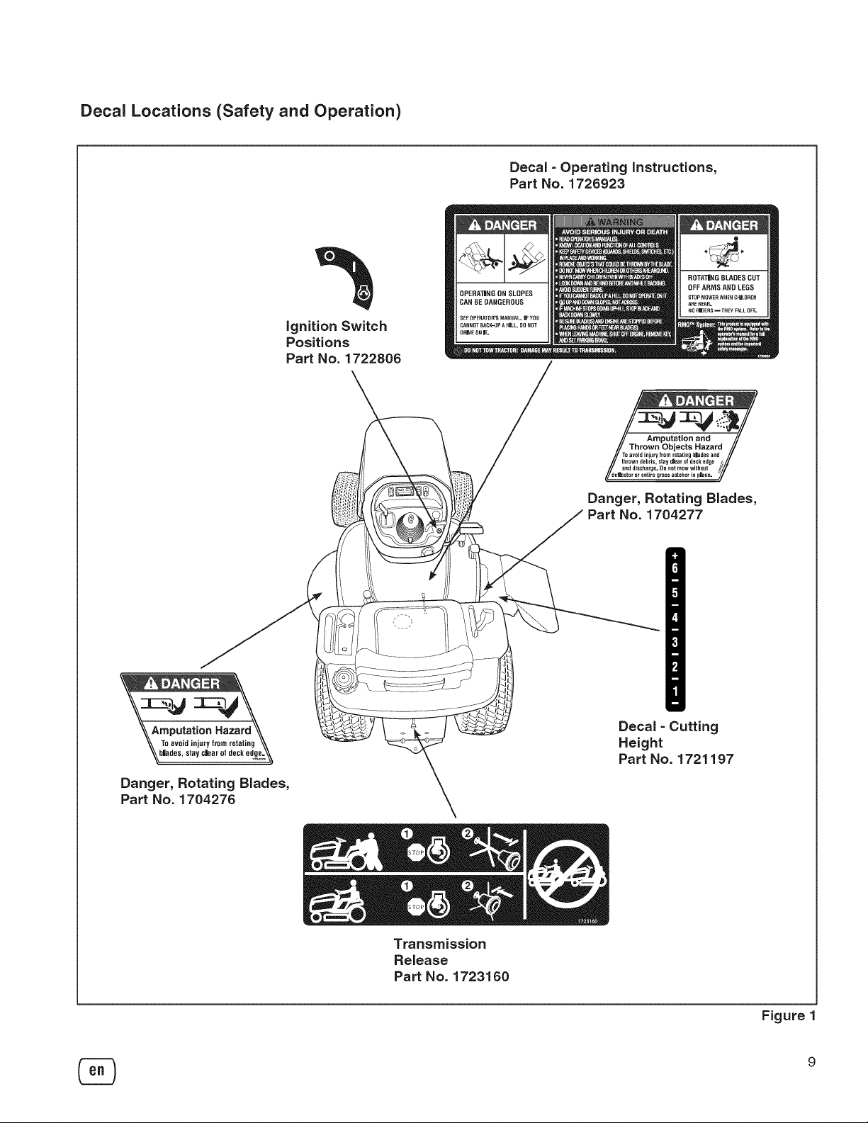
Decal Locations (Safety and Operation)
ignition Switch
Positions
Part No. 1722806
Decal - Operating instructions,
Part No. 1728923
TO avoid injury from rntating bhges anJ //
thrown debris, stay c_ar of deck edge
and discharge. DO not mow without _
/t_ii! r enlire grass catcher in place.
Danger, Rotating Blades,
Part No. 1704277
_Amputation Hazard
\\ To avoidinjury from rotating \\
_b'ad0a, ,ray0'0atofdon,o_,\_
Danger, Rotating Blades,
Part No. 1704276
DecaJ - Cutting
Height
Part No. 1721197
Transmission
Release
Part No. 1723160
Figure
9
Page 10
m mw
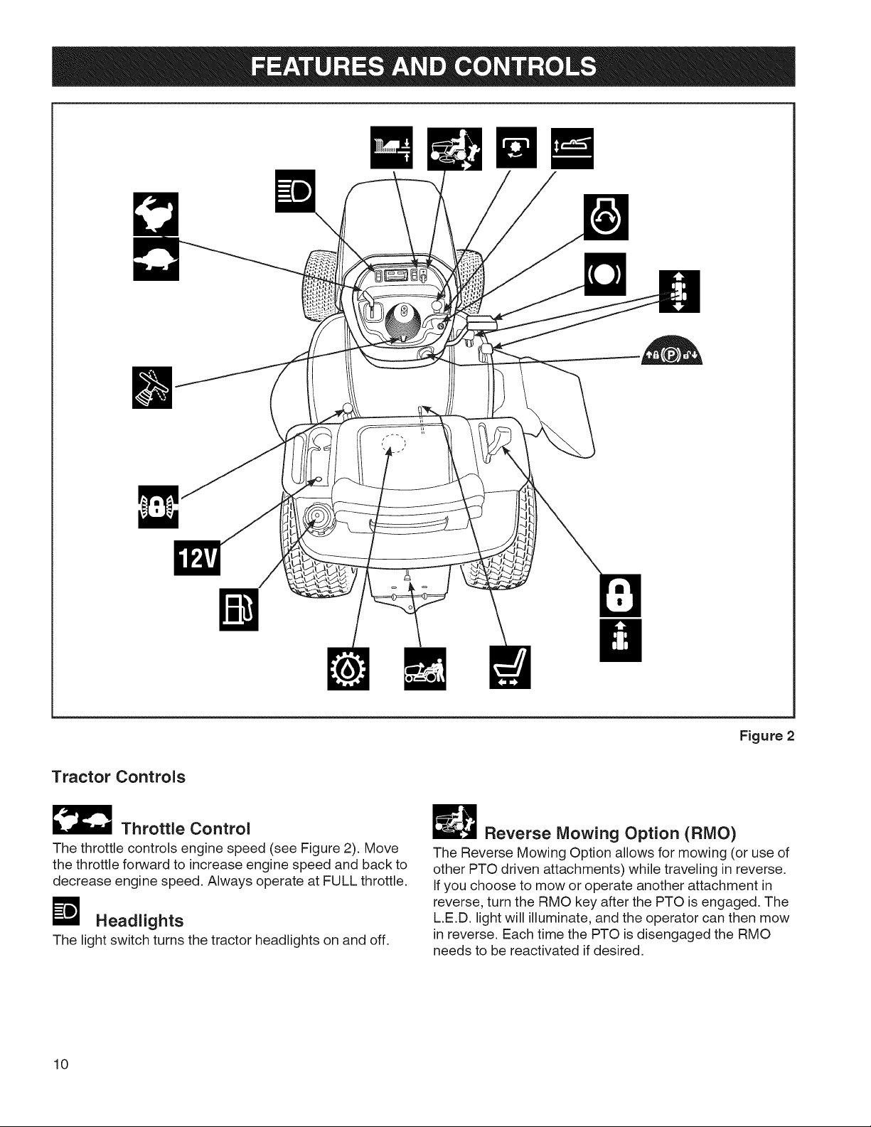
Tractor Controls
_ Throttle Control
The throttle controls engine speed (see Figure 2). Move
the throttle forward to increase engine speed and back to
decrease engine speed. Always operate at FULL throttle.
Headlights
The light switch turns the tractor headlights on and off.
10
Figure 2
_ Reverse Mowing Option (RMO)
The Reverse Mowing Option allows for mowing (or use of
other PTO driven attachments) while traveling in reverse.
If you choose to mow or operate another attachment in
reverse, turn the RMO key after the PTO is engaged. The
L.E.D. light will illuminate, and the operator can then mow
in reverse. Each time the PTO is disengaged the RMO
needs to be reactivated if desired.
Page 11
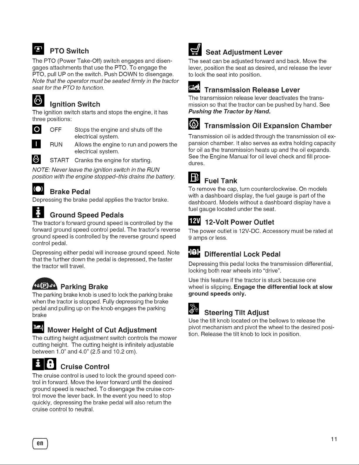
PTO Switch
The PTO (Power Take-Off) switch engages and disen-
gages attachments that use the PTO. To engage the
PTO, pull UP on the switch. Push DOWN to disengage.
Note that the operator must be seated firmly in the tractor
seat for the PTO to function.
_1 ignition Switch
The ignition switch starts and stops the engine, it has
three positions:
m OFF
H RUN Allows the engine to run and powers the
W START Cranks the engine for starting.
NOTE. Never leave the ignition switch in the RUN
position with the engine stopped-this drains the battery.
Stops the engine and shuts off the
electrical system.
electrical system.
D Brake Pedal
Depressing the brake pedal applies the tractor brake.
H Ground Speed Pedals
The tractor's forward ground speed is controlled by the
forward ground speed control pedal. The tractor's reverse
ground speed is controlled by the reverse ground speed
control pedal.
Depressing either pedal will increase ground speed. Note
that the further down the pedal is depressed, the faster
the tractor will travel.
Parking Drake
The parking brake knob is used to lock the parking brake
when the tractor is stopped. Fully depressing the brake
pedal and pulling up on the knob engages the parking
brake
Mower Height of Cut Adjustment
The cutting height adjustment switch controls the mower
cutting height. The cutting height is infinitely adjustable
between 1.0" and 4.0" (2.5 and 10.2 cm).
Seat Adjustment Lever
The seat can be adjusted forward and back. Move the
lever, position the seat as desired, and release the lever
to lock the seat into position.
Transmission Release Lever
The transmission release lever deactivates the trans-
mission so that the tractor can be pushed by hand. See
Pushing the Tractor by Hand.
L_ Transmission Oil Expansion Chamber
Transmission oil is added through the transmission oil ex-
pansion chamber. It also serves as extra holding capacity
for oil as the transmission heats up and the oil expands.
See the Engine Manual for oil level check and fill proce-
dures.
r_ Fuel Tank
To remove the cap, turn counterclockwise. On models
with a dashboard display, the fuel gauge is part of the
dashboard. Models without a dashboard display have a
fuel gauge located under the seat.
12-Volt Power Outlet
The power outlet is 12V-DC. Accessory must be rated at
9 amps or less.
Differential Lock Pedal
Depressing this pedal locks the transmission differential,
locking both rear wheels into "drive".
Use this feature if the tractor is stuck because one
wheel is slipping. Engage the differential lock at slow
ground speeds only.
Steering Tilt Adjust
Use the tilt knob located on the bellows to release the
pivot mechanism and pivot the wheel to the desired posi-
tion. Release the tilt knob to lock in position.
HD coot,ol
The cruise control is used to lock the ground speed con-
trol in forward. Move the lever forward until the desired
ground speed is reached. To disengage the cruise con-
trol move the lever back. In the event you need to stop
quickly, depressing the brake pedal will also return the
cruise control to neutral.
11
Page 12
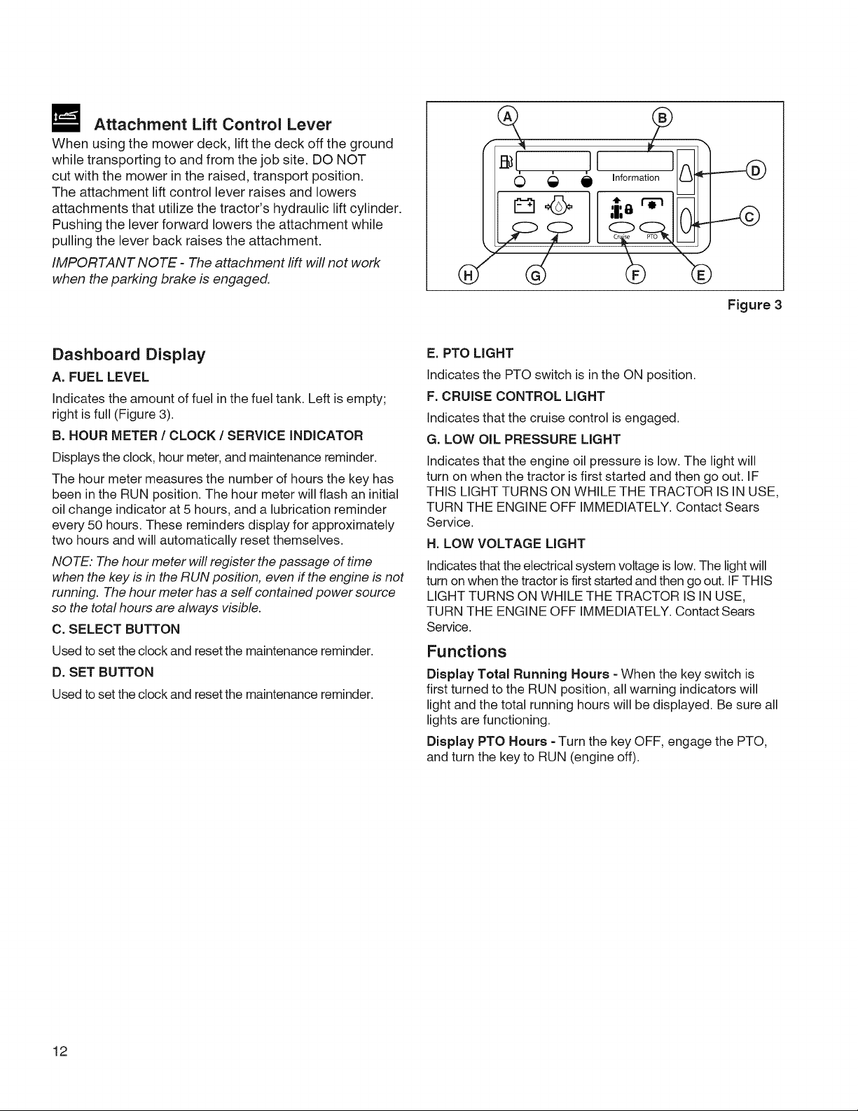
Attachment Lift Control Lever
When using the mower deck, lift the deck off the ground
while transporting to and from the job site. DO NOT
cut with the mower in the raised, transport position.
The attachment lift control lever raises and lowers
attachments that utilize the tractor's hydraulic lift cylinder.
Pushing the lever forward lowers the attachment while
pulling the lever back raises the attachment.
IMPORTANT NOTE - The attachment lift will not work
when the parking brake is engaged.
0 € e Information
rmd
0
Figure 3
Dashboard Display
A. FUEL LEVEL
Indicates the amount of fuel in the fuel tank. Left is empty;
right is full (Figure 3).
B. HOUR METER / CLOCK / SERVICE INDICATOR
Displays the clock, hour meter, and maintenance reminder.
The hour meter measures the number of hours the key has
been in the RUN position. The hour meter will flash an initial
oil change indicator at 5 hours, and a lubrication reminder
every 50 hours. These reminders display for approximately
two hours and will automatically reset themselves.
NOTE. The hour meter will register the passage of time
when the key is in the RUN position, even ff the engine is not
running. The hour meter has a serf contained power source
so the total hours are always visible.
C. SELECT BUTTON
Used to set the clock and reset the maintenance reminder.
D. SET BUTTON
Used to set the clock and reset the maintenance reminder.
E. PTO LIGHT
Indicates the PTO switch is in the ON position.
F. CRUISE CONTROL LIGHT
Indicates that the cruise control is engaged.
G. LOW OIL PRESSURE LIGHT
Indicates that the engine oil pressure is low. The light will
turn on when the tractor is first started and then go out. IF
THIS LIGHT TURNS ON WHILE THE TRACTOR IS IN USE,
TURN THE ENGINE OFF IMMEDIATELY. Contact Sears
Service.
H. LOW VOLTAGE LIGHT
Indicates that the electrical system voltage is low. The light will
turn on when the tractor is first started and then go out. IF THIS
LIGHT TURNS ON WHILE THE TRACTOR IS IN USE,
TURN THE ENGINE OFF IMMEDIATELY. Contact Sears
Service.
Functions
Display Total Running Hours - When the key switch is
first turned to the RUN position, all warning indicators will
light and the total running hours will be displayed. Be sure all
lights are functioning.
Display PTO Hours - Turn the key OFF, engage the PTO,
and turn the key to RUN (engine off).
12
Page 13
Set the Clock - Start the engine, leave the engine running.
Depress the select button (C) for three (3) seconds and
release. Depress set button and HOLD to advance time.
Depress select button to select minutes. Depress and HOLD
set button (D) to advance time. Leave alone for 5 seconds
and clock will activate. Shut off engine.
Demonstration Mode - With the engine off, hold down the
set button (D) and turn the key switch to RUN.
Maintenance Reminder - A maintenance reminder will
display in the information window (B) after the first 5 hours
of operation, and then after every 50 hours. The reminder
will automatically reset after 5 hours. The reminder can be
manually reset by turning the key switch from OFF to RUN
(with engine off) and then depressing the set (D) and select
(C) buttons simultaneously for 5 seconds.
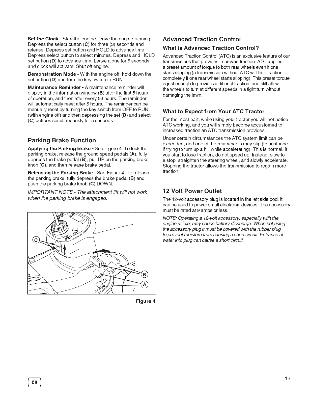
Parking Brake Function
Applying the Parking Brake - See Figure 4. To lock the
parking brake, release the ground speed pedals (A), fully
depress the brake pedal (B), pull UP on the parking brake
knob (C), and then release brake pedal.
Releasing the Parking Brake - See Figure 4. To release
the parking brake, fully depress the brake pedal (B) and
push the parking brake knob (C) DOWN.
IMPORTANT NOTE - The attachment rift will not work
when the parking brake is engaged..
Advanced Traction Control
What is Advanced Traction Control?
Advanced Traction Control (ATC) is an exclusive feature of our
transmissions that provides improved traction. ATC applies
a preset amount of torque to both rear wheels even if one
starts slipping (a transmission without ATC will lose traction
completely if one rear wheel startsslipping). This preset torque
isjust enough to provide additional traction, and still allow
the wheels to turn at different speeds in a tight turn without
damaging the lawn.
What to Expect from Your ATC Tractor
For the most part, while using your tractor you will not notice
ATC working, and you will simply become accustomed to
increased traction an ATC transmission provides.
Under certain circumstances the ATC system limit can be
exceeded, and one of the rear wheels may slip (for instance
if trying to turn up a hill while accelerating). This is normal. If
you start to lose traction, do not speed up. Instead, slow to
a stop, straighten the steering wheel, and slowly accelerate.
Stopping the tractor allows the transmission to regain more
traction.
12 Volt Power Outlet
The 12-volt accessory plug is located in the left side pod. It
can be used to power small electronic devices. The accessory
must be rated at 9 amps or less.
NOTE. Operating a 12-volt accessory, especially with the
engine at idle, may cause battery discharge. When not using
the accessory plug it must be covered with the rubber plug
to prevent moisture from causing a short circuit. Entrance of
water into plug can cause a short circu#.
Figure 4
13
Page 14
Safety Interlock System Tests
This unit is equipped with safety interlock switches and
other safety devices. These safety systems are present
for your safety: do not attempt to bypass safety switches,
and never tamper with safety devices.
WARNING
if the unit does not pass a safety test, do not
operate it. See your authorized dealer.
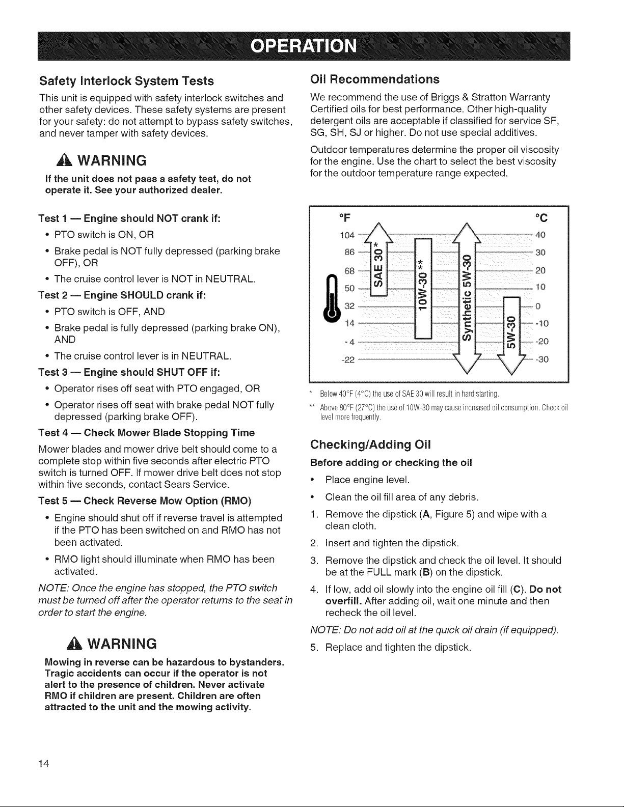
Oil Recommendations
We recommend the use of Briggs & Stratton Warranty
Certified oils for best performance. Other high-quality
detergent oils are acceptable if classified for service SF,
SG, SH, SJ or higher. Do not use special additives.
Outdoor temperatures determine the proper oil viscosity
for the engine. Use the chart to select the best viscosity
for the outdoor temperature range expected.
Test 1 m Engine should NOT crank if:
• PTO switch is ON, OR
• Brake pedal is NOT fully depressed (parking brake
OFF), OR
The cruise control lever is NOT in NEUTRAL.
Test 2 m Engine SHOULD crank if:
PTO switch is OFF, AND
• Brake pedal is fully depressed (parking brake ON),
AND
The cruise control lever is in NEUTRAL.
Test 3 = Engine should SHUT OFF if:
Operator rises off seat with PTO engaged, OR
• Operator rises off seat with brake pedal NOT fully
depressed (parking brake OFF).
Test 4 -- Check Mower Blade Stopping Time
Mower blades and mower drive belt should come to a
complete stop within five seconds after electric PTO
switch is turned OFF. If mower drive belt does not stop
within five seconds, contact Sears Service.
Test 5 _ Check Reverse Mow Option (RMO)
• Engine should shut off if reverse travel is attempted
if the PTO has been switched on and RMO has not
been activated.
RMO light should illuminate when RMO has been
activated.
NOTE: Once the engine has stopped, the PTO switch
must be turned off after the operator returns to the seat in
order to start the engine.
WARNING
Mowing in reverse can be hazardous to bystanders.
Tragic accidents can occur if the operator is not
alert to the presence of children. Never activate
RMO if children are present. Children are often
attracted to the unit and the mowing activity.
°C
* Below40°F(4°C)theuseofSAE30will resultinhardstarting.
** Above80°F(27°C)the useof10W-30maycauseincreased0il consumption.Check0il
levelmorefrequently.
Checking/Adding Oil
Before adding or checking the oil
• Place engine level.
• Clean the oil fill area of any debris.
1. Remove the dipstick (A, Figure 5) and wipe with a
clean cloth.
2. Insert and tighten the dipstick.
3. Remove the dipstick and check the oil level. It should
be at the FULL mark (B) on the dipstick.
4. If low, add oil slowly into the engine oil fill (C). Do not
overfill. After adding oil, wait one minute and then
recheck the oil level.
NOTE. Do not add off at the quick off drain (if equipped).
5. Replace and tighten the dipstick.
14
Page 15
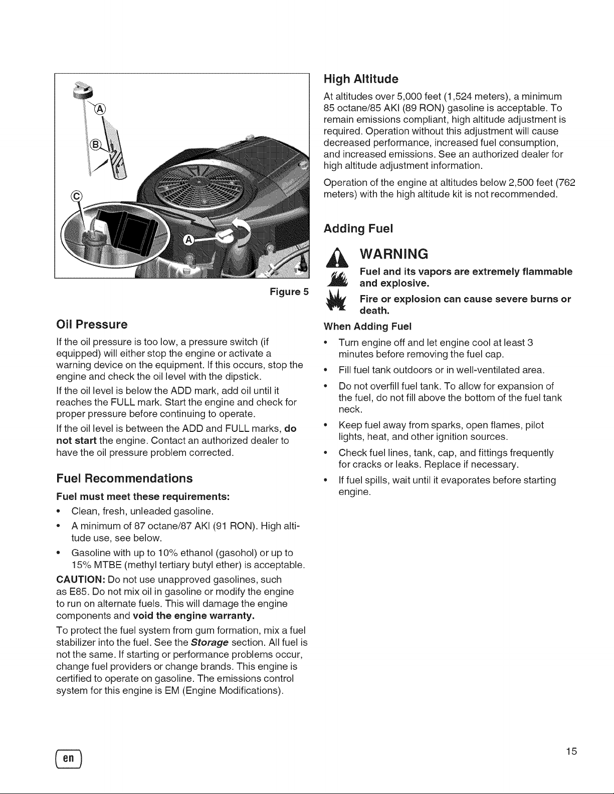
Figure 5
Oil Pressure
If the oil pressure is too low, a pressure switch (if
equipped) will either stop the engine or activate a
warning device on the equipment. If this occurs, stop the
engine and check the oil level with the dipstick.
If the oil level is below the ADD mark, add oil until it
reaches the FULL mark. Start the engine and check for
proper pressure before continuing to operate.
If the oil level is between the ADD and FULL marks, do
not start the engine. Contact an authorized dealer to
have the oil pressure problem corrected.
Fuel Recommendations
Fuel must meet these requirements:
• Clean, fresh, unleaded gasoline.
A minimum of 87 octane/87 AKI (91 RON). High alti-
tude use, see below.
Gasoline with up to 10% ethanol (gasohol) or up to
15% MTBE (methyl tertiary butyl ether) is acceptable.
CAUTION: Do not use unapproved gasolines, such
as E85. Do not mix oil in gasoline or modify the engine
to run on alternate fuels. This will damage the engine
components and void the engine warranty.
To protect the fuel system from gum formation, mix afuel
stabilizer into the fuel. See the Storage section. All fuel is
not the same. If starting or performance problems occur,
change fuel providers or change brands. This engine is
certified to operate on gasoline. The emissions control
system for this engine is EM (Engine Modifications).
High Altitude
At altitudes over 5,000 feet (1,524 meters), a minimum
85 octane/85 AKI (89 RON) gasoline is acceptable. To
remain emissions compliant, high altitude adjustment is
required. Operation without this adjustment will cause
decreased performance, increased fuel consumption,
and increased emissions. See an authorized dealer for
high altitude adjustment information.
Operation of the engine at altitudes below 2,500 feet (762
meters) with the high altitude kit is not recommended.
Adding Fuel
WARNING
Fuel and its vapors are extremely flammable
and explosive.
Fire or explosion can cause severe burns or
death.
When Adding Fuel
Turn engine off and let engine cool at least 3
minutes before removing the fuel cap.
Fill fuel tank outdoors or in well-ventilated area.
Do not overfill fuel tank. To allow for expansion of
the fuel, do not fill above the bottom of the fuel tank
neck.
Keep fuel away from sparks, open flames, pilot
lights, heat, and other ignition sources.
Check fuel lines, tank, cap, and fittings frequently
for cracks or leaks. Replace if necessary.
If fuel spills, wait until it evaporates before starting
engine.
15
Page 16
.
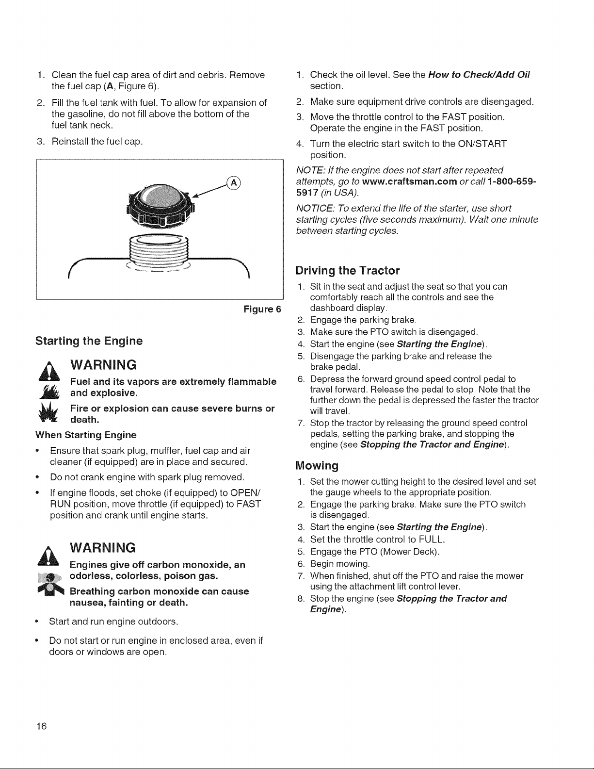
Clean the fuel cap area of dirt and debris. Remove
the fuel cap (A, Figure 6).
.
Fill the fuel tank with fuel. To allow for expansion of
the gasoline, do not fill above the bottom of the
fuel tank neck.
3. Reinstall the fuel cap.
Figure 6
Starting the Engine
WARNING
Fuel and its vapors are extremely flammable
and explosive.
Fire or explosion can cause severe burns or
death.
When Starting Engine
• Ensure that spark plug, muffler, fuel cap and air
cleaner (if equipped) are in place and secured.
• Do not crank engine with spark plug removed.
• If engine floods, set choke (if equipped) to OPEN/
RUN position, move throttle (if equipped) to FAST
position and crank until engine starts.
WARNING
Engines give off carbon monoxide, an
odorless, colorless, poison gas.
Breathing carbon monoxide can cause
nausea, fainting or death.
o
Start and run engine outdoors.
o
Do not start or run engine in enclosed area, even if
doors or windows are open.
1. Check the oil level. See the How to Check/Add Oil
section.
2. Make sure equipment drive controls are disengaged.
3. Move the throttle control to the FAST position.
Operate the engine in the FAST position.
4. Turn the electric start switch to the ON/START
position.
NOTE: If the engine does not start after repeated
attempts, go to www.craftsman.com or call 1=800=659=
5e 17 (in USA).
NOTICE: To extend the life of the starter, use short
starting cycles (five seconds maximum). Wait one minute
between starting cycles.
Driving the Tractor
1. Sit in the seat and adjust the seat so that you can
comfortably reach all the controls and see the
dashboard display.
2. Engage the parking brake.
3. Make sure the PTO switch is disengaged.
4. Start the engine (see Starting the Engine).
5. Disengage the parking brake and release the
brake pedal.
6. Depress the forward ground speed control pedal to
travel forward. Release the pedal to stop. Note that the
further down the pedal is depressed the faster the tractor
will travel.
7. Stop the tractor by releasing the ground speed control
pedals, setting the parking brake, and stopping the
engine (see Stopping the Tractor and Engine).
Mowing
1. Set the mower cutting height to the desired level and set
the gauge wheels to the appropriate position.
2. Engage the parking brake. Make sure the PTO switch
is disengaged.
3. Start the engine (see Starting the Engine).
4. Set the throttle control to FULL.
5. Engage the PTO (Mower Deck).
6. Begin mowing.
7. When finished, shut off the PTO and raise the mower
using the attachment lift control lever.
8. Stop the engine (see Stopping the Tractorand
Engine).
16
Page 17
WARNING
The engine will shut off if the reverse ground speed
pedal is depressed while the PTO is on and the
RMO has not been activated. The operator should
always turn the PTO off prior to driving across
on roads, paths or any area that maybe used by
other vehicles. Sudden loss of drive could create a
hazard.
Mowing in Reverse (RMO)
WARNING
Mowing in reverse can be hazardous to bystanders.
Tragic accidents can occur if the operator is not
alert to the presence of children. Never activate
RMO if children are present. Children are often
attracted to the unit and the mowing activity.
If an operator chooses to mow in reverse, the RMO system
can be used. To use the Reverse Mowing Option (RMO) turn
the RMO key after the PTO is engaged. The L.E.D. light will
illuminate, and the operator can then mow in reverse. Each
time the PTO is engaged the RMO needs to be reactivated if
desired. The key should be removed to restrict access to the
RMO feature.
Attachment Operation in Reverse
If an operator chooses to operate a PTO driven attachment
in reverse, the RMO system can be used. To use the
Reverse Mowing Option (RMO) turn the RMO key after
the PTO is engaged. The L.E.D. light will illuminate, and
the operator can then operate the attachment in reverse.
Each time the PTO is disengaged the RMO needs to be
reactivated if desired. The key should be removed to restrict
access to the RMO feature.
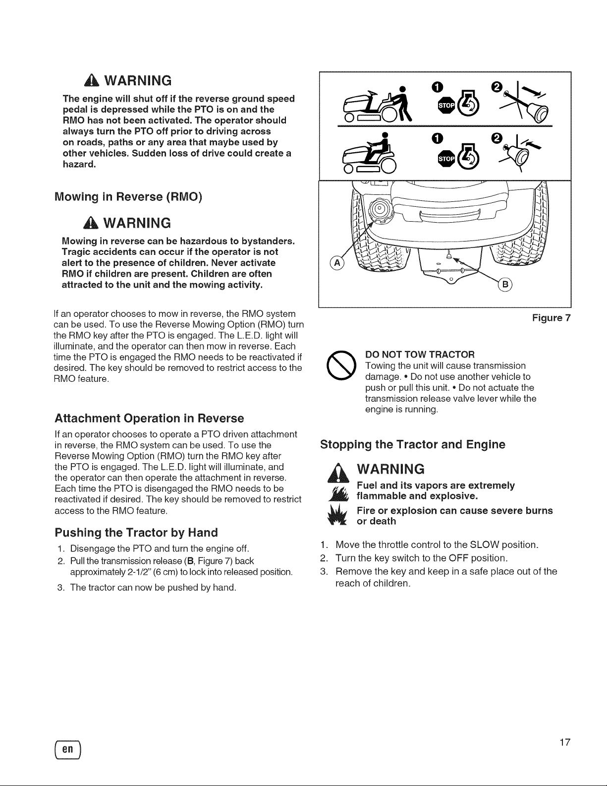
Pushing the Tractor by Hand
1. Disengage the PTO and turn the engine off.
2. Pull the transmission release (B, Figure 7) back
approximately 2-1/2" (6 cm) to lock into released position.
3. The tractor can now be pushed by hand.
Figure 7
DO NOT TOW TRACTOR
®
Towing the unit will cause transmission
damage. = Do not use another vehicle to
push or pull this unit. * Do not actuate the
transmission release valve lever while the
engine is running.
Stopping the Tractor and Engine
WARNING
Fuel and its vapors are extremely
flammable and explosive.
Fire or explosion can cause severe burns
or death
1. Move the throttle control to the SLOW position.
2. Turn the key switch to the OFF position.
3. Remove the key and keep in a safe place out of the
reach of children.
17
Page 18
Adjusting Mower Cutting Height
The cutting height is adjustable between 1.0" and 4.0" (2,5
and 10,2 cm).
The cutting height adjustment switch (A, Figure 8) controls
the mower cutting height. This same switch also controls
the spout rotator motor when a snowthrower is installed.
The arrows on the switch correspond to the direction of
adjustment (UP arrow raises cutting height, RIGHT arrow
rotates the spout right, etc). When the adjustment indicator
has reached the end of its travel, release the switch; holding
the switch down will damage the motor.
trtr
D
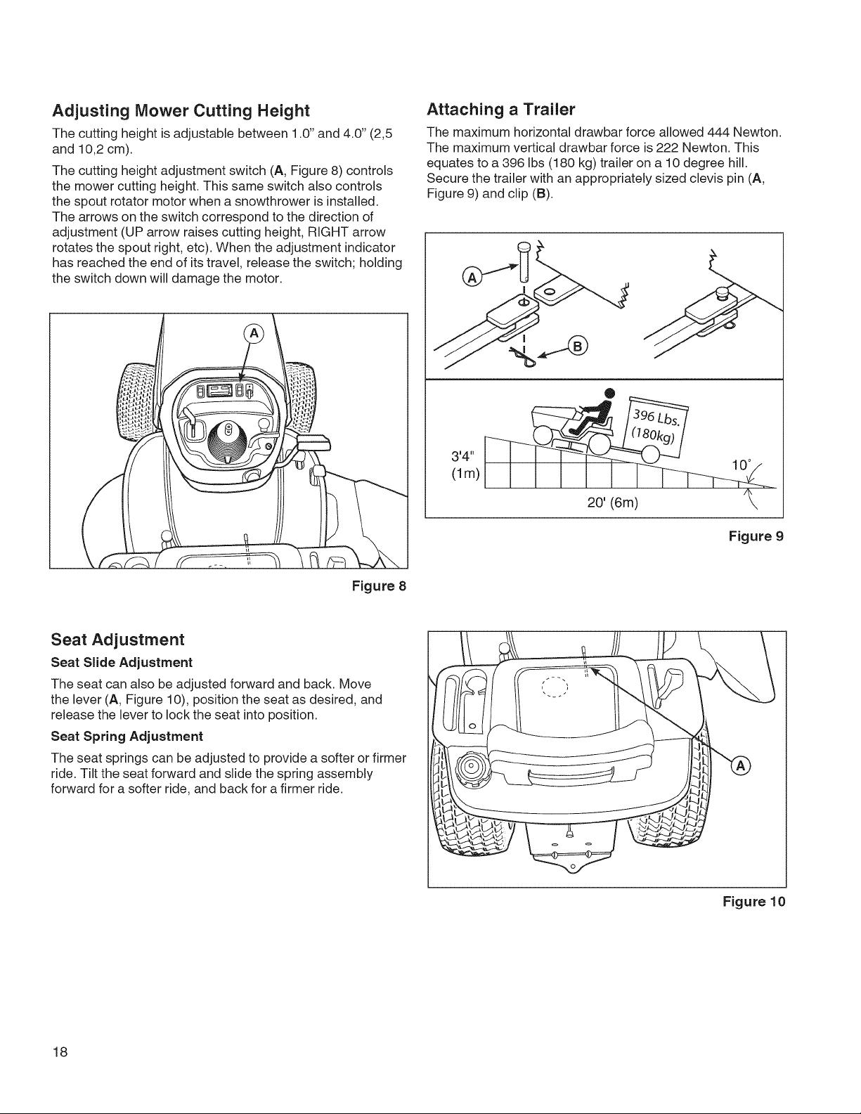
Attaching a Trailer
The maximum horizontal drawbar force allowed 444 Newton.
The maximum vertical drawbar force is 222 Newton. This
equates to a 396 Ibs (180 kg) trailer on a 10 degree hill.
Secure the trailer with an appropriately sized clevis pin (A,
Figure 9) and clip (B).
_Z
Figure 8
Seat Adjustment
Seat Slide Adjustment
The seat can also be adjusted forward and back. Move
the lever (A, Figure 10), position the seat as desired, and
release the lever to lock the seat into position.
Seat Spring Adjustment
The seat springs can be adjusted to provide a softer or firmer
ride. Tilt the seat forward and slide the spring assembly
forward for a softer ride, and back for a firmer ride.
'4"
(lm)
10 °
20' (6m)
Figure 9
18
Figure 10
Page 19
Maintenance Chart
Every 8 Hours or Daily
Check safety interlock system
Clean debris off tractor and mower deck
Clean debris from engine compartment
Every 25 Hours or Annually *
Check mower blade stopping time
Check tractor and mower for loose hardware
Check tire pressure
Every 50 Hours or Annually *
Check tractor brakes
Clean battery and cables
See Dealer Annually to
Lubricate tractor and mower
Check mower blades **
* Whichever comes first
** Check blades more often in regions with sandy soils or
high dust conditions.
iiiiiiiiiiiiiiiiiiiiiiiiiiiiiiiiiiiiiiiiiiiiiiiiiiiiiiiiiiiiiiiiiiiiiiiiiiiiiiiiiiiiiiiiiiiiiiiiiiiiiiiiiiiiiiiiiiiiiiiiiiiiiiiiiiiiiiiiiiiiiiiiiiiiiiiiiiiiiiiiiiiiiiiiiiiiiiiiiiiiiiiiiiiiiiii
First 5 iHours _____________________________________________________________________________________________________________________________________________________
Change engine oil -see engine manual
Every 8 Hours or Dally .....
Check engine oil level - see engine manual
Every 25 Hours or Annually*
Clean engine air filter and pre-cleaner **
Every 50 Hours or Annually *
Change engine oil
Replace oil filter
Replace air filter
Replace pre-cleaner
see Dealer Annually to
Inspect muffler and spark arrester
Replace spark plug
Replace fuel filter
Clean engine air cooling system
* Whichever comes first
** Clean more often in dusty conditions or when airborne
debris is present.
Emissions Control
Maintenance, replacement, or repair of the emissions control
devices and systems may be performed by any non-road
engine repair establishment or individual. However, to obtain
"no charge" emissions control service, the work must be per-
formed by a factory authorized dealer. Seethe Emissions
Warranty.
Check Mower Blade Stopping Time
Mower blades and mower drive belt should come to a
complete stop within five seconds after the electric PTO
switch is turned off.
1. With tractor in neutral, PTO disengaged and operator in
seat, start the engine.
2. Look over the left-hand footrest at the mower drive belt.
Engage the PTO and wait several seconds. Disengage
the PTO and check the amount of time it takes for the
mower drive belt to stop.
3. If mower drive belt does not stop within five seconds, see
your dealer.
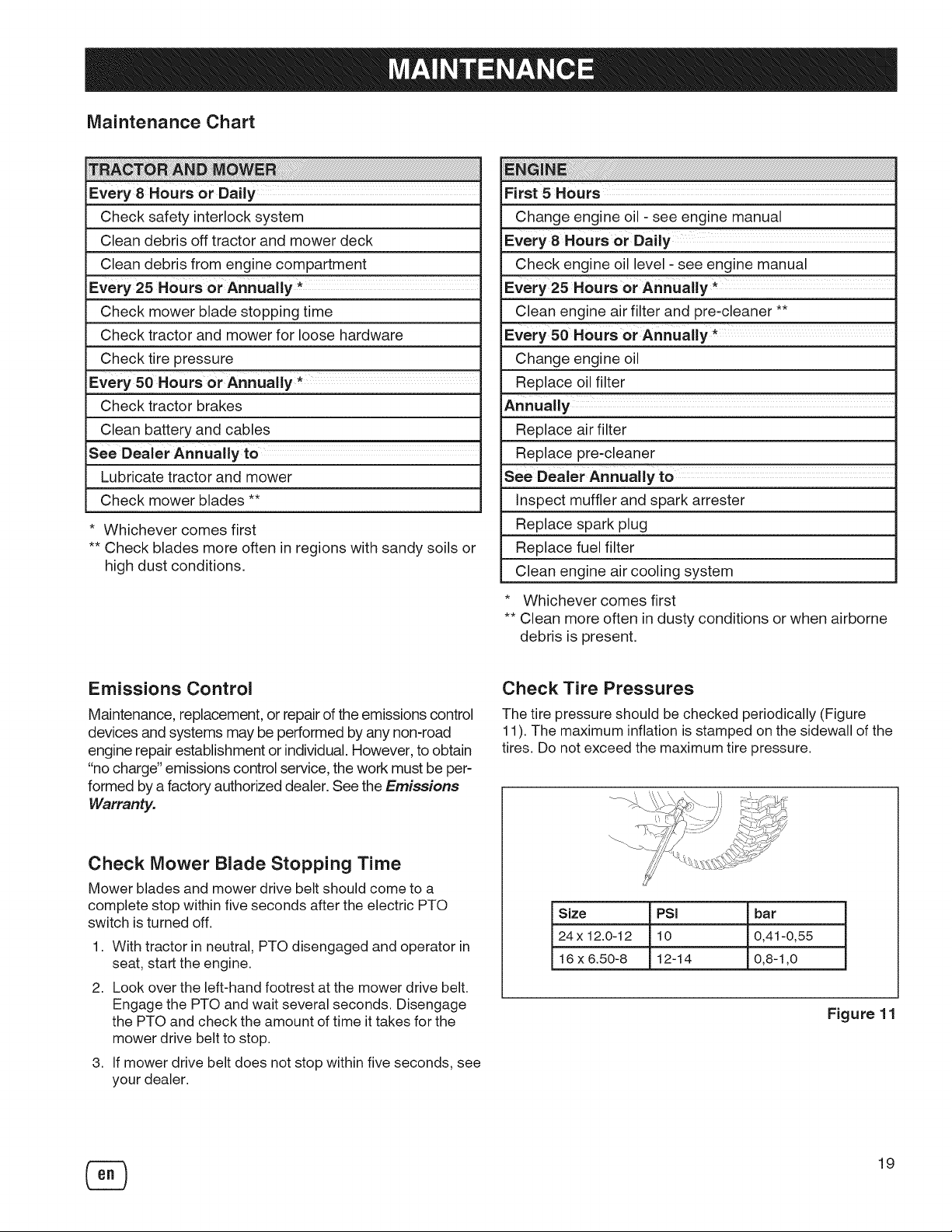
Check Tire Pressures
The tire pressure should be checked periodically (Figure
11). The maximum inflation is stamped on the sidewall of the
tires. Do not exceed the maximum tire pressure.
Size PSi bar
24x 12.0-12 10 0,41-0,55
16 x 6.50-8 12-14 0,8-1,0
Figure 11
19
Page 20
Electronic Fuel Management System
The Electronic Fuel Management System monitors engine
temperature, engine speed, and battery voltage to adjust
the choke during engine starting and warm up. There are no
adjustments on the system. If starting or operation problems
occur, contact Sears Service.
NOTICE." Make sure to follow the steps below or the
Electronic Fuel Management System could be damaged.
• Never start the engine if the battery cables are loose.
Turn the key to the off position before disconnecting,
removing and/or installing the battery.
Never use a battery charger to start the engine.
Never disconnect the battery cables while the engine is
running.
When connecting the battery cables, first connect the
positive (+) cable and then connect the negative (-) cable
to the battery.
When charging the battery, turn the ignition switch to the
off position and disconnect the negative (-) battery cable
from the battery.
Do not spray water directly on the Electronic Control Unit.
Battery Charging
WARNING
Keep open flames and sparks away from the
battery; the gasses coming from it are highly
explosive. Ventilate the battery well during
charging.
A dead battery or one too weak to start the engine may
be the result of a defect in the charging system or other
electrical component. If there is any doubt about the cause
of the problem, see your dealer. If you need to replace the
battery, follow the steps under Cleaning the Battery and
Cables.
To charge the battery, follow the instructions provided by
the battery charger manufacturer as well as all warnings
included in the safety rules sections of this book. Charge
the battery until fully charged. Do not charge at a rate higher
than 10 amps.
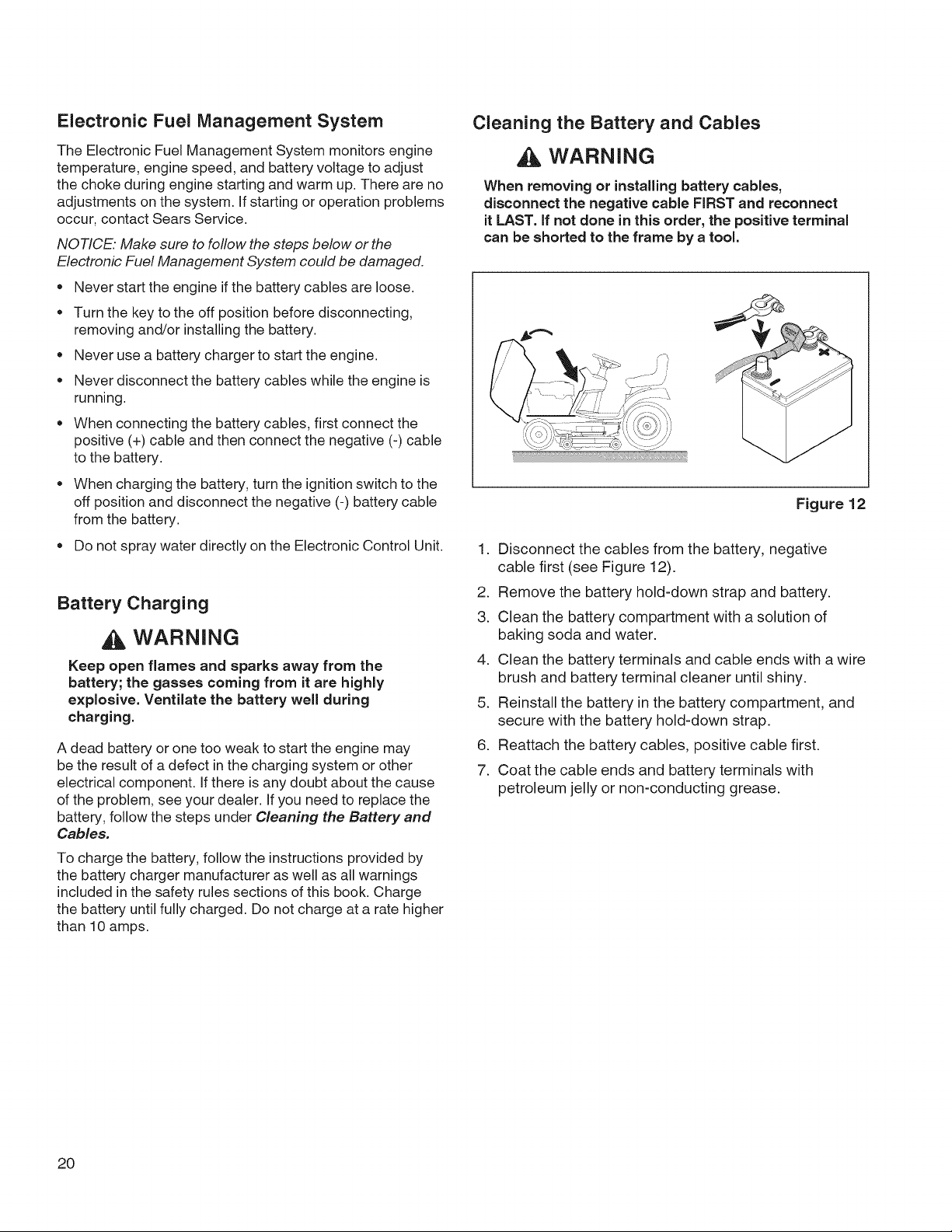
Cleaning the Battery and Cables
WARNING
When removing or installing battery cables,
disconnect the negative cable FIRST and reconnect
it LAST. if not done in this order, the positive terminal
can be shorted to the frame by a tool.
Figure 12
1. Disconnect the cables from the battery, negative
cable first (see Figure 12).
2. Remove the battery hold-down strap and battery.
3. Clean the battery compartment with a solution of
baking soda and water.
4. Clean the battery terminals and cable ends with a wire
brush and battery terminal cleaner until shiny.
5. Reinstall the battery in the battery compartment, and
secure with the battery hold-down strap.
6. Reattach the battery cables, positive cable first.
7. Coat the cable ends and battery terminals with
petroleum jelly or non-conducting grease.
20
Page 21
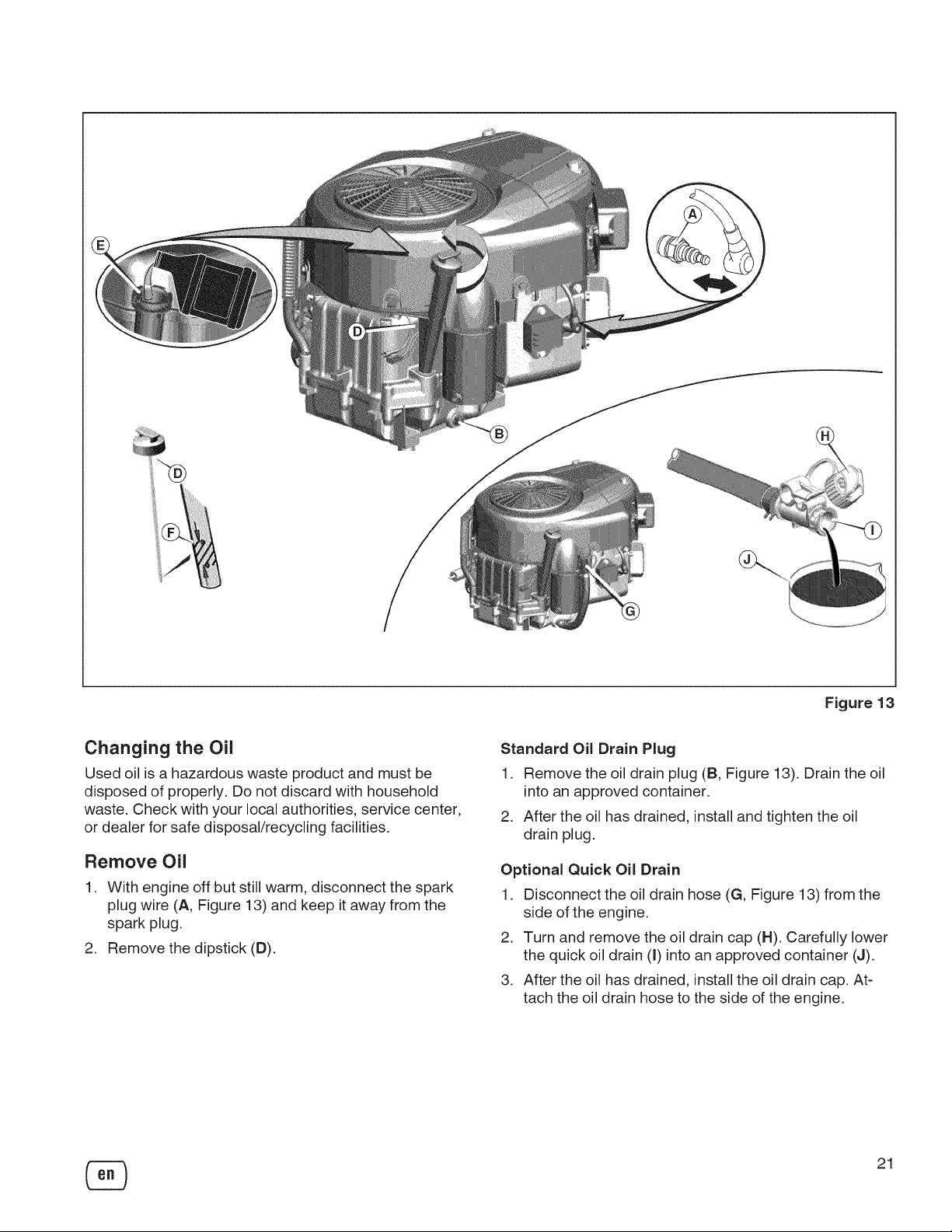
Figure 13
Changing the Oil
Used oil isa hazardous waste product and must be
disposed of properly. Do not discard with household
waste. Check with your local authorities, service center,
or dealer for safe disposal/recycling facilities.
Remove Oil
1. With engine off but still warm, disconnect the spark
plug wire (A, Figure 13) and keep it away from the
spark plug.
2. Remove the dipstick (D).
Standard Oil Drain Plug
1. Remove the oil drain plug (B, Figure 13). Drain the oil
into an approved container.
2. After the oil has drained, install and tighten the oil
drain plug.
Optional Quick Oil Drain
1. Disconnect the oil drain hose (G, Figure 13) from the
side of the engine.
2. Turn and remove the oil drain cap (H). Carefully lower
the quick oil drain (I) into an approved container (J).
3. After the oil has drained, install the oil drain cap. At-
tach the oil drain hose to the side of the engine.
21
Page 22
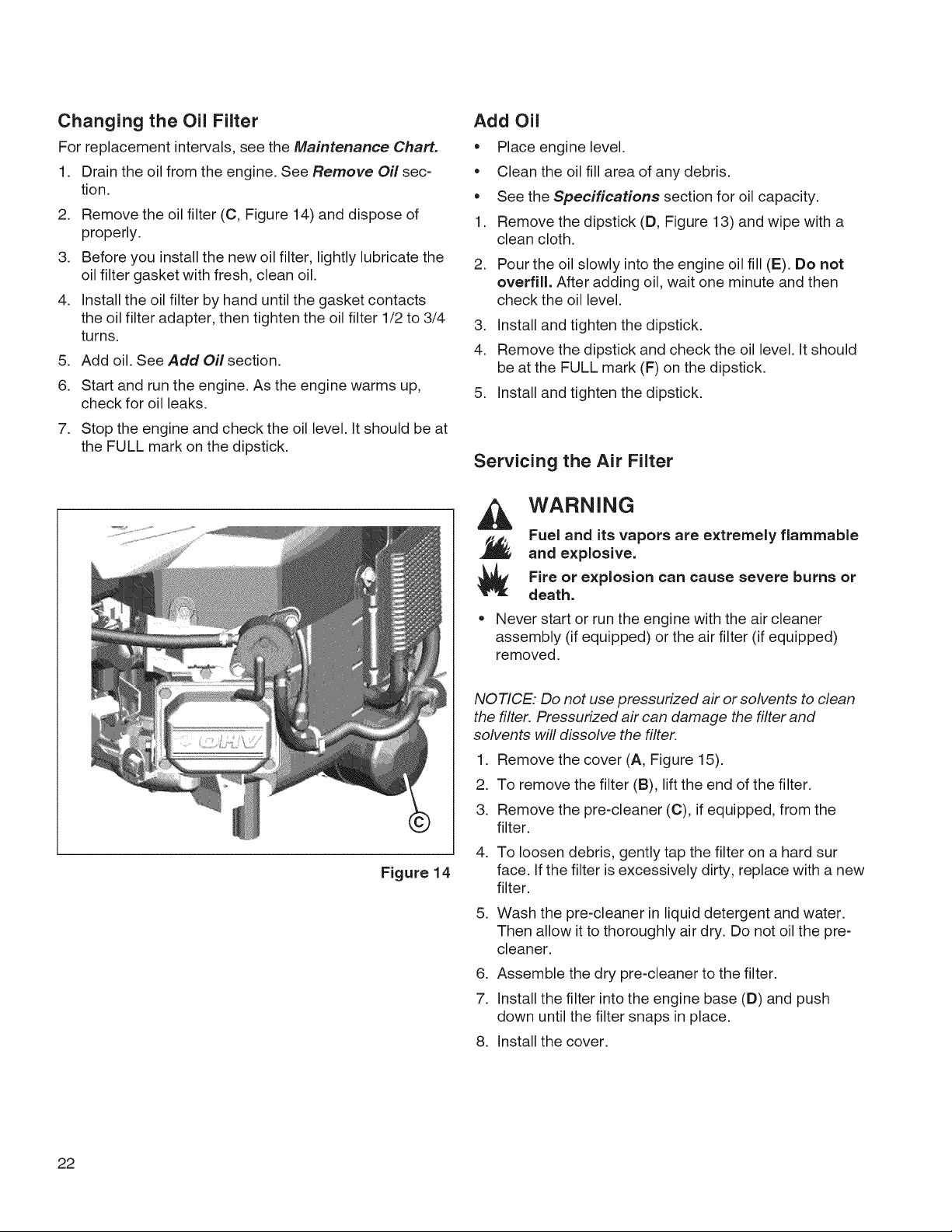
Changing the Oil Filter
For replacement intervals, see the Maintenance Chart.
1. Drain the oil from the engine. See Remove Oil sec-
tion.
2. Remove the oil filter (C, Figure 14) and dispose of
properly.
3. Before you install the new oil filter, lightly lubricate the
oil filter gasket with fresh, clean oil.
4. Install the oil filter by hand until the gasket contacts
the oil filter adapter, then tighten the oil filter 1/2 to 3/4
turns.
5. Add oil. See Add Oil section.
6. Start and run the engine. As the engine warms up,
check for oil leaks.
7. Stop the engine and check the oil level. It should be at
the FULL mark on the dipstick.
Add Oil
• Place engine level.
Clean the oil fill area of any debris.
See the Specifications section for oil capacity.
1. Remove the dipstick (D, Figure 13) and wipe with a
clean cloth.
2. Pour the oil slowly into the engine oil fill (E). Do not
overfill. After adding oil, wait one minute and then
check the oil level.
3. Install and tighten the dipstick.
4. Remove the dipstick and check the oil level. It should
be at the FULL mark (F) on the dipstick.
5. Install and tighten the dipstick.
Servicing the Air Filter
WARNING
Fuel and its vapors are extremely flammable
and explosive.
Fire or explosion can cause severe burns or
death.
Figure 14
Never start or run the engine with the air cleaner
assembly (if equipped) or the air filter (if equipped)
removed.
NOTICE. Do not use pressurized air or solvents to clean
the filter. Pressurized air can damage the filter and
solvents will dissolve the filter.
1. Remove the cover (A, Figure 15).
2. To remove the filter (B), lift the end of the filter.
3. Remove the pre-cleaner (C), if equipped, from the
filter.
4. To loosen debris, gently tap the filter on a hard sur
face. If the filter is excessively dirty, replace with a new
filter.
5. Wash the pre-cleaner in liquid detergent and water.
Then allow it to thoroughly air dry. Do not oil the pre-
cleaner.
6. Assemble the dry pre-cleaner to the filter.
7. Installthe filter into the engine base (D) and push
down until the filter snaps in place.
8. Installthe cover.
22
Page 23
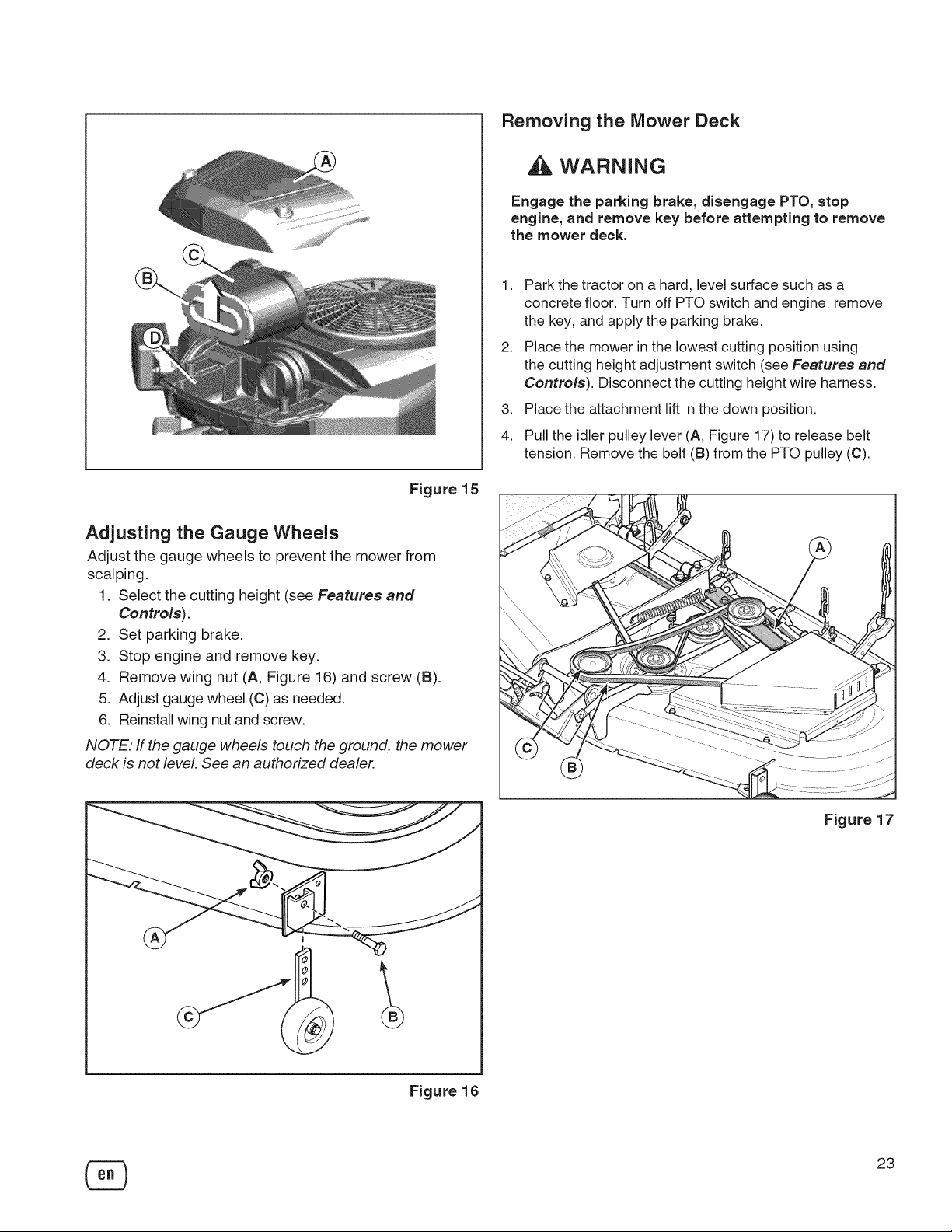
Figure 15
Adjusting the Gauge Wheels
Adjust the gauge wheels to prevent the mower from
scalping.
1. Select the cutting height (see Features and
Controls).
2. Set parking brake.
3. Stop engine and remove key.
4. Remove wing nut (A, Figure 16) and screw (B).
5. Adjust gauge wheel (C) as needed.
6. Reinstall wing nut and screw.
NOTE. ff the gauge wheels touch the ground, the mower
deck is not level. See an authorized dealer.
Removing the Mower Deck
WARNING
Engage the parking brake, disengage PTO, stop
engine, and remove key before attempting to remove
the mower deck.
1,
Park the tractor on a hard, level surface such as a
concrete floor. Turn off PTO switch and engine, remove
the key, and apply the parking brake.
2,
Place the mower in the lowest cutting position using
the cutting height adjustment switch (see Features and
Controls). Disconnect the cutting height wire harness.
3,
Place the attachment lift in the down position.
4.
Pull the idler pulley lever (A, Figure 17) to release belt
tension. Remove the belt (B) from the PTO pulley (C).
Figure 16
Figure 17
23
Page 24

5,
Remove cotter pin (D, Figure 18) and disconnect the
cutting height chain (E) from the hook in tractor frame.
Repeat for the other side.
6,
Disconnect the attachment lift chain from the hook in
tractor frame (see Figure 19). Repeat for the other side.
/
\
Figure 18
Figure 19
Figure 20
7,
Turn the wheels straight ahead. Pull back on the spring-
loaded lever and lift the mower hitch off tractor hitch
bracket (see 1-2, Figure 20).
8,
Turn the wheels fully left, and slide mower deck out from
under the right side of the tractor.
24
Page 25
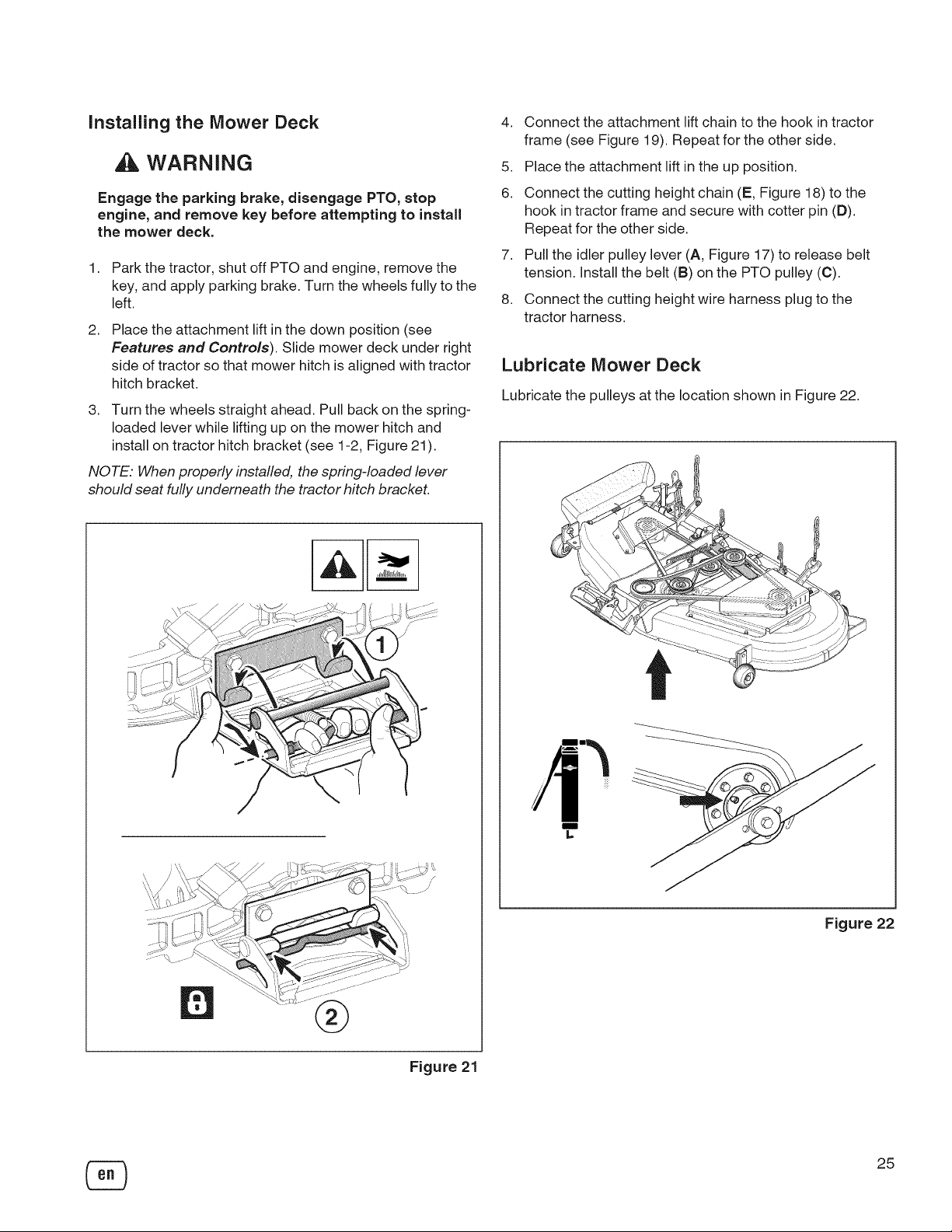
Installing the Mower Deck
WARNING
Engage the parking brake, disengage PTO, stop
engine, and remove key before attempting to install
the mower deck.
1. Park the tractor, shut off PTO and engine, remove the
key, and apply parking brake. Turn the wheels fully to the
left.
2,
Place the attachment lift in the down position (see
Features and Controls). Slide mower deck under right
side of tractor so that mower hitch is aligned with tractor
hitch bracket.
3. Turn the wheels straight ahead. Pull back on the spring-
loaded lever while lifting up on the mower hitch and
install on tractor hitch bracket (see 1-2, Figure 21 ).
NOTE. When properly installed, the spring-loaded lever
should seat fully underneath the tractor hitch bracket.
4. Connect the attachment lift chain to the hook in tractor
frame (see Figure 19). Repeat for the other side.
5. Place the attachment lift in the up position.
6. Connect the cutting height chain (E, Figure 18) to the
hook in tractor frame and secure with cotter pin (D).
Repeat for the other side.
7. Pull the idler pulley lever (A, Figure 17) to release belt
tension. Install the belt (B) on the PTO pulley (C).
8. Connect the cutting height wire harness plug to the
tractor harness.
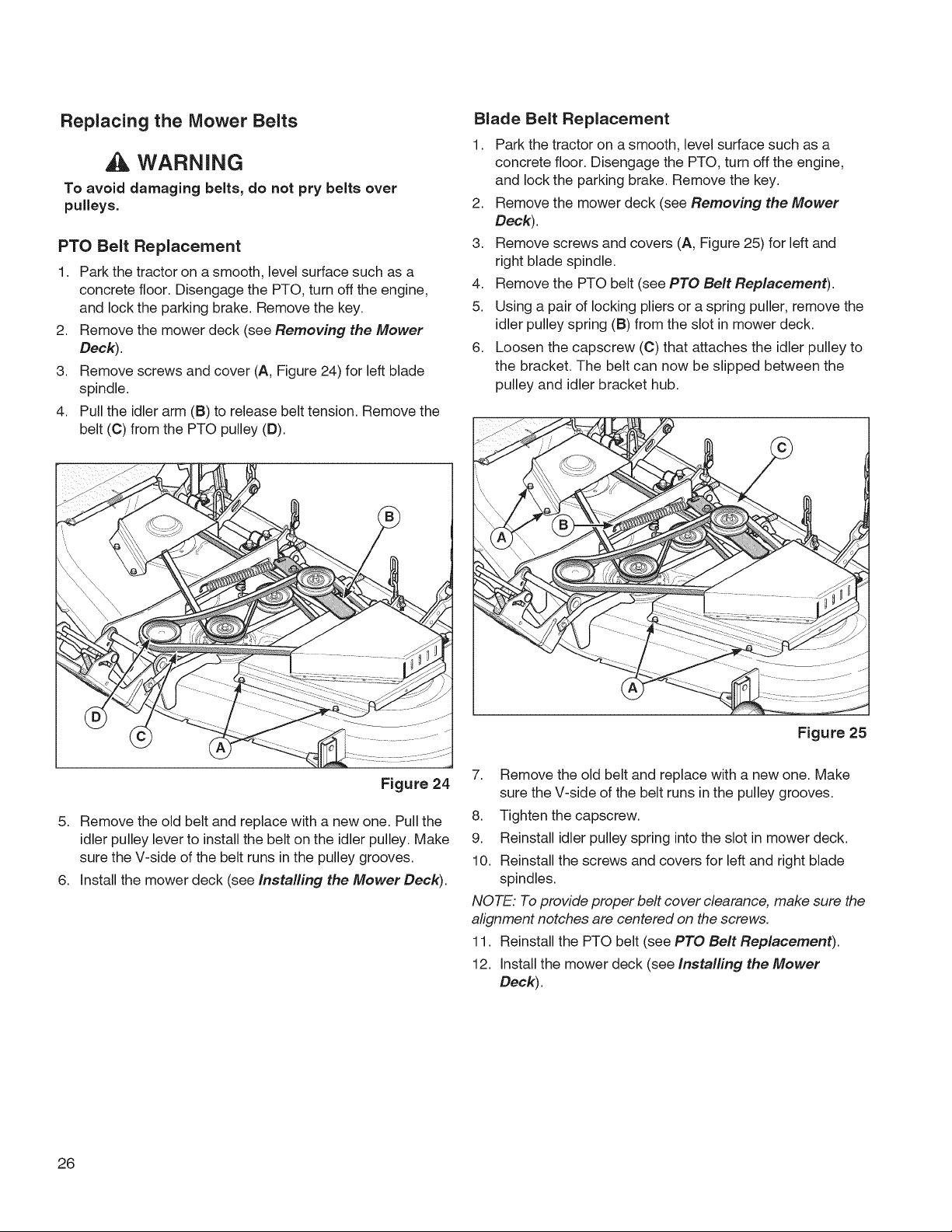
Lubricate Mower Deck
Lubricate the pulleys at the location shown in Figure 22.
®
Figure 21
m
L,
Figure 22
25
Page 26
Replacing the Mower Belts
WARNING
To avoid damaging belts, do not pry belts over
pulleys.
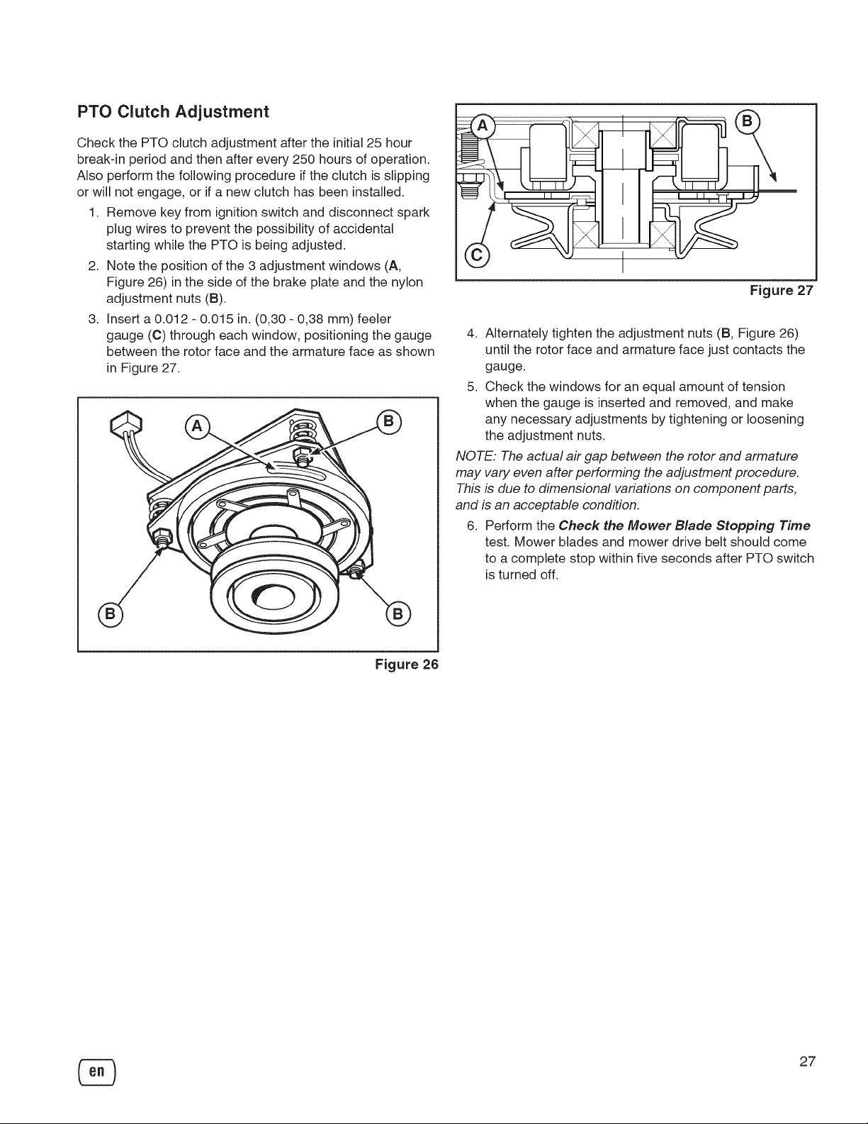
PTO Belt Replacement
1. Park the tractor on a smooth, level surface such as a
concrete floor. Disengage the PrO, turn off the engine,
and lock the parking brake. Remove the key.
2. Remove the mower deck (see Removing the Mower
Deck).
3. Remove screws and cover (A, Figure 24) for left blade
spindle.
4. Pull the idler arm (B) to release belt tension. Remove the
belt (C) from the PTO pulley (D).
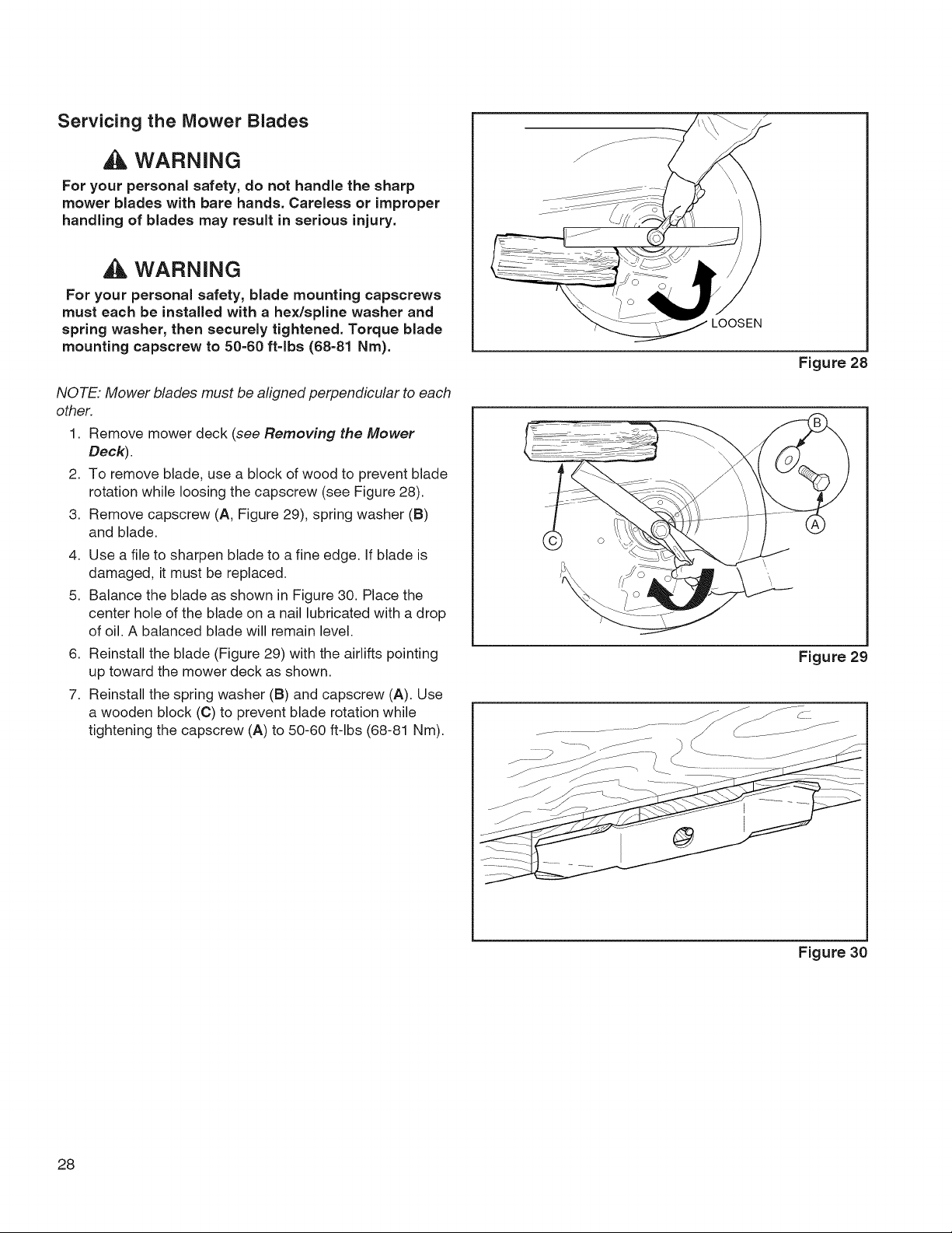
Blade Belt Replacement
1. Park the tractor on a smooth, level surface such as a
concrete floor. Disengage the PrO, turn off the engine,
and lock the parking brake. Remove the key.
2. Remove the mower deck (see Removing the Mower
Deck).
3. Remove screws and covers (A, Figure 25) for left and
right blade spindle.
4. Remove the PrO belt (see PTO Belt Replacement).
5. Using a pair of locking pliers or a spring puller, remove the
idler pulley spring (B) from the slot in mower deck.
6. Loosen the capscrew (C) that attaches the idler pulley to
the bracket. The belt can now be slipped between the
pulley and idler bracket hub.
Figure 24
5. Remove the old belt and replace with a new one. Pull the
idler pulley lever to install the belt on the idler pulley. Make
sure the V-side of the belt runs in the pulley grooves.
6. Install the mower deck (see Installing the Mower Deck).
26
Figure 25
7. Remove the old belt and replace with a new one. Make
sure the V-side of the belt runs in the pulley grooves.
8. Tighten the capscrew.
9. Reinstall idler pulley spring into the slot in mower deck.
10. Reinstall the screws and covers for left and right blade
spindles.
NOTE. To provide proper belt cover clearance, make sure the
alignment notches are centered on the screws.
11. Reinstall the PrO belt (see PTO Belt Replacement).
12. Install the mower deck (see Installing the Mower
Deck).
Page 27
PTO Clutch Adjustment
Check the PTO clutch adjustment after the initial 25 hour
break-in period and then after every 250 hours of operation.
Also perform the following procedure if the clutch is slipping
or will not engage, or if a new clutch has been installed.
1. Remove key from ignition switch and disconnect spark
plug wires to prevent the possibility of accidental
starting while the PTO is being adjusted.
2. Note the position of the 3 adjustment windows (A,
Figure 26) in the side of the brake plate and the nylon
adjustment nuts (B).
3. Insert a 0.012 - 0.015 in. (0,30 - 0,38 mm) feeler
gauge (C) through each window, positioning the gauge
between the rotor face and the armature face as shown
in Figure 27.
I
I
Figure 27
4. Alternately tighten the adjustment nuts (B, Figure 26)
until the rotor face and armature face just contacts the
gauge.
5. Check the windows for an equal amount of tension
when the gauge is inserted and removed, and make
any necessary adjustments by tightening or loosening
the adjustment nuts.
NOTE. The actual air gap between the rotor and armature
may vary even after performing the adjustment procedure.
This is due to dimensional variations on component parts,
and is an acceptable condition.
6. Perform the Check the Mower Blade Stopping Time
test. Mower blades and mower drive belt should come
to a complete stop within five seconds after PTO switch
is turned off.
®
Figure 26
27
Page 28
Servicing the Mower Blades
WARNING
For your personal safety, do not handle the sharp
mower blades with bare hands. Careless or improper
handling of blades may result in serious injury.
WARNING
For your personal safety, blade mounting capscrews
must each be installed with a heyJspline washer and
spring washer, then securely tightened. Torque blade
mounting capscrew to 50-60 ft-lbs (68=81 Nm).
NOTE." Mower blades must be aligned perpendicular to each
other.
1. Remove mower deck (see Removing the Mower
Deck).
2. To remove blade, use a block of wood to prevent blade
rotation while loosing the capscrew (see Figure 28).
3. Remove capscrew (A, Figure 29), spring washer (B)
and blade.
4. Use a file to sharpen blade to a fine edge. If blade is
damaged, it must be replaced.
5. Balance the blade as shown in Figure 30. Place the
center hole of the blade on a nail lubricated with a drop
of oil. A balanced blade will remain level.
6. Reinstall the blade (Figure 29) with the airlifts pointing
up toward the mower deck as shown.
7. Reinstall the spring washer (B) and capscrew (A). Use
a wooden block (C) to prevent blade rotation while
tightening the capscrew (A) to 50-60 ft-lbs (68-81 Nm).
LOOSEN
Figure 28
Figure 29
28
Figure 30
Page 29
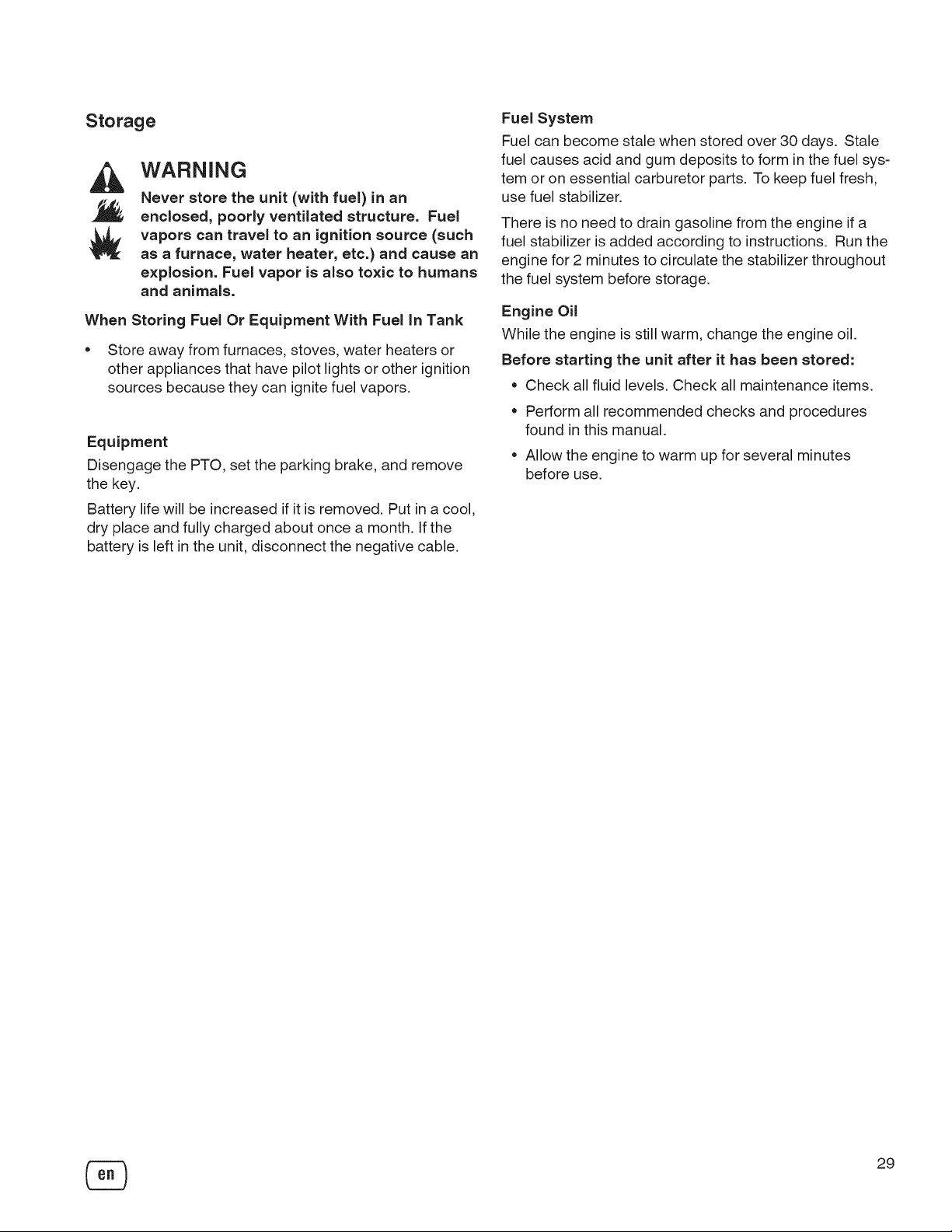
Storage
WARNING
Never store the unit (with fuel) in an
enclosed, poorly ventilated structure. Fuel
vapors can travel to an ignition source (such
as a furnace, water heater, etc.) and cause an
explosion. Fuel vapor is also toxic to humans
and animals.
When Storing Fuel Or Equipment With Fuel In Tank
• Store away from furnaces, stoves, water heaters or
other appliances that have pilot lights or other ignition
sources because they can ignite fuel vapors.
Equipment
Disengage the PTO, set the parking brake, and remove
the key.
Battery life will be increased if it is removed. Put in a cool,
dry place and fully charged about once a month. If the
battery is left in the unit, disconnect the negative cable.
Fuel System
Fuel can become stale when stored over 30 days. Stale
fuel causes acid and gum deposits to form in the fuel sys-
tem or on essential carburetor parts. To keep fuel fresh,
use fuel stabilizer.
There is no need to drain gasoline from the engine if a
fuel stabilizer is added according to instructions. Run the
engine for 2 minutes to circulate the stabilizer throughout
the fuel system before storage.
Engine Oil
While the engine is still warm, change the engine oil.
Before starting the unit after it has been stored:
• Check all fluid levels. Check all maintenance items.
• Perform all recommended checks and procedures
found in this manual.
• Allow the engine to warm up for several minutes
before use.
29
Page 30
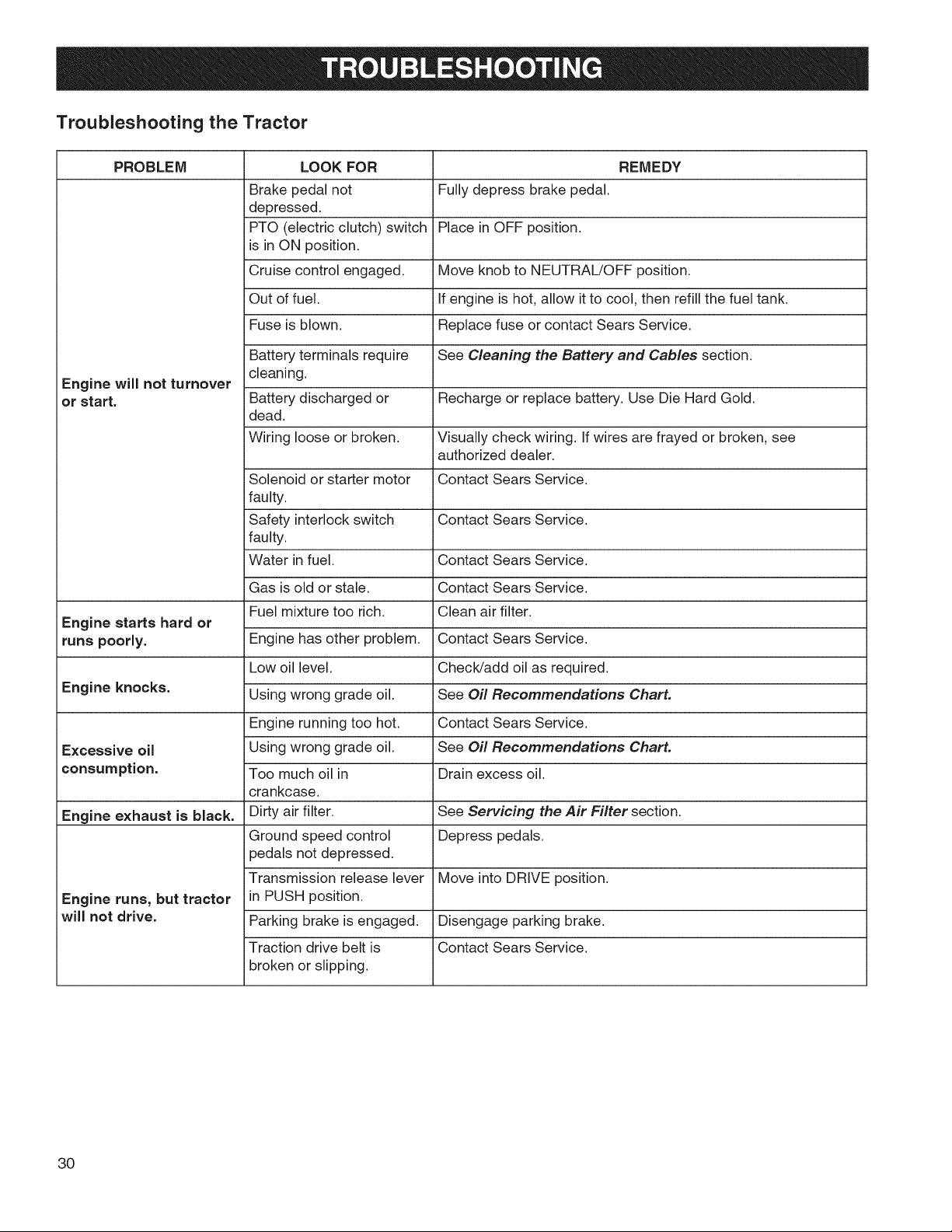
Troubleshooting the Tractor
PROBLEM LOOK FOR REMEDY
Brake pedal not i Fully depress brake pedal.
depressed.
PTO (electric clutch) switch Place in OFF position.
is in ON position.
Cruise control engaged. Move knob to NEUTRAL/OFF position.
Out of fuel. i lf engine is hot, allow it to cool, then refill the fuel tank.
Fuse is blown, i Replace fuse or contact Sears Service.
Battery terminals require iSee Cleaning the Battery and Cables section.
Engine will not turnover
ior start. Battery discharged or i Recharge or replace battery. Use Die Hard Gold.
cleaning.
dead.
Wiring loose or broken, i Visually check wiring. If wires are frayed or broken, see
iauthorized dealer.
Solenoid or starter motor Contact Sears Service.
faulty.
Safety interlock switch Contact Sears Service.
faulty.
Water in fuel. Contact Sears Service.
Gas is old or stale. Contact Sears Service.
Engine starts hard or
runs poorly. Engine has other problem. Contact Sears Service.
Engine knocks.
Excessive oil Using wrong grade oil. See Oil Recommendations Chart.
iconsumption. Too much oil in Drain excess oil.
Engine exhaust is black. Dirty air filter. See Servicing the Air Filter section.
Engine runs, but tractor in PUSH position.
will not drive. Parking brake is engaged, i Disengage parking brake.
Fuel mixture too rich. Clean air filter.
Low oil level. Check/add oil as required.
Using wrong grade oil. See Oil Recommendations CharL
Engine running too hot. Contact Sears Service.
crankcase.
Ground speed control i Depress pedals.
pedals not depressed.
Transmission release lever Move into DRIVE position.
Traction drive belt is Contact Sears Service.
broken or slipping.
30
Page 31

Troubleshooting the Tractor (Continued)
PROBLEM LOOK FOR
Brake will not hold.
Tractor steers hard or Improper tire inflation.
handles poorly. Front wheel spindle
Internal brake worn.
Steering linkage is loose.
bearings dry.
Contact Sears Service.
Contact Sears Service.
See Check Tire Pressure section.
Contact Sears Service.
REMEDY
Troubleshooting the Mower
PROBLEM LOOK FOR REMEDY
i Lift linkage not properly Contact Sears Service.
Mower will not raise, attached or damaged.
Mower not leveled Level the mower. See Setup Instructions.
properly.
Mower cut is uneven, iTractor tires not properly See Check Tire Pressure section.
inflated.
i Engine speed too slow. Set to full throttle.
Mower cut is rough Ground speed too fast. Slow down.
looking.
Mower has other problem. Contact Sears Service.
i Engine speed too slow. Set to full throttle.
Ground speed to fast. Slow down.
i Dirty or clogged air filter. See Servicing the Air Filter section.
Engine stalls easily with Cutting height set too low. Cut tall grass at maximum cutting height during first pass.
mower engaged, i Engine not up to operating Run engine for several minutes to warm-up.
itemperature.
i Starting mower in tall Start the mower in a cleared area.
grass.
Excessive mower i Mower has other problem. Contact Sears Service.
vibration.
Engine runs and tractor
drives, but mower will Mower has other problem. Contact Sears Service.
not drive.
PTO not engaged. Engage the PTO.
31
Page 32

ENGINE
K71 TRANSMISSION
Briggs & Stratton Type
Make Briggs& Stratton® Hydraulic Fluid
Model Professional Series TM Speeds
Horsepower 30 Gross HP @3400 +/- 100 rpm @3400 rpm
Displacement 49.43 cu in. (810 cc) Continuous Torque
Electrical System Alternator: 16 amp DC Reg. Output
Battery: 12 volt, 500 CCA
DieHard Gold
64 oz (1,9 L)Oil Capacity
CHASSIS
FuelTank Capacity 3.6 Gallons (13,6 L)
Front Wheels Tire Size: 16x 6.5-8
Rear Wheels Tire Size: 24 x 12.0-12
MOWER
Width of Cut
Number of Blades
Base Deck Platform
Cutting Height
Cutting Positions
DIMENSIONS
Hyd rostatic Tuff Torq K71
lOw 30 Premium Engine Oil
Forward: 0-8.0 MPH (0-12,9 km/h)
Reverse: 0-5.0 MPH (0-8,1 km/h)
410 ft-lbs (554 Nm)
54" (137,2 cm)
3
Side Discharge
1.0 - 4.0 in. (2,5 - 10,2 cm)
Infinite
Overall Length
Overall Width
Height
75" (190,5 cm)
61" (154,9 cm)
47" (119,4 cm)
Power Rating
The gross power rating for individual gas engine models is labeled in accordance with SAE (Society of Automotive
Engineers) code J1940 (Small Engine Power & Torque Rating Procedure), and rating performance has been obtained
and corrected in accordance with SAE J1995 (Revision 2002-05). Torque values are derived at 3060 RPM; horsepower
values are derived at 3600 RPM. The gross power curves can be viewed at www.BRIGGSandSTRATTON.COM. Net
power values are taken with exhaust and air cleaner installed whereas gross power values are collected without these
attachments. Actual gross engine power will be higher than net engine power and is affected by, among other things,
ambient operating conditions and engine-to-engine variability. Given the wide array of products on which engines
are placed, the gas engine may not develop the rated gross power when used in a given piece of power equipment.
This difference is due to avariety of factors including, but not limited to, the variety of engine components (air cleaner,
exhaust, charging, cooling, carburetor, fuel pump, etc.), application limitations, ambient operating conditions (tempera-
ture, humidity, altitude), and engine-to-engine variability. Due to manufacturing and capacity limitations, Briggs & Strat-
ton may substitute an engine of higher rated power for this Series engine.
Parts and Accessories
Contact an authorized dealer for parts and accessories.
32
Page 33

CRAFTSMAN FULL WARRANTY
FOR THREE YEARS from the date of purchase, all non-expendable parts of this riding equipment are war-
ranted against any defects in material or workmanship. A defective non-expendable part will receive free
in-home repair or replacement if repair is impossible.
FOR FIVE YEARS from the date of purchase, the frame and front axle of this riding equipment are warranted
against any defects in material or workmanship. A defective frame or front axle will receive free in-home re-
pair or replacement if repair is impossible.
FOR 90 DAYS from the date of purchase, the battery (an expendable part) of this riding equipment is war-
ranted against any defects in material or workmanship (our testing proves that it will not hold a charge). A
defective battery will receive free in-home replacement.
ADDITIONAL LIFETIME LIMITED WARRANTY on CAST IRON FRONT AXLE (if equipped)
FOR AS LONG AS IT IS USED by the original owner after the fifth year from the date of purchase, the cast
iron front axle (if equipped) of this riding equipment is warranted against any defects in material or workman-
ship. With proof of purchase, a defective cast iron front axle will receive free in-home replacement.
WARRANTY SERVICE
For warranty coverage details to obtain free repair or replacement, call 1-800-659-5917 or visit the web site:
www.craftsman.com.
In all cases above, if part repair or replacement is impossible, the riding equipment will be replaced free of
charge with the same or an equivalent model.
All of the above warranty coverage is void if this riding equipment is ever used while providing commercial
services or if rented to another person.
This warranty covers ONLY defects in material and workmanship. Warranty coverage does NOT include:
• Expendable parts (except battery) that can wear out from normal use within the warranty period, includ-
ing but not limited to blades, spark plugs, air cleaners, belts, and oil filters.
• Standard maintenance servicing, oil changes, or tune-ups.
• Tire replacement or repair caused by punctures from outside objects, such as nails, thorns, stumps, or
glass.
• Tire or wheel replacement or repair resulting from normal wear, accident, or improper operation or main-
tenance.
Repairs necessary because of operator abuse, including but not limited to damage caused by towing
objects beyond the capability of the riding equipment, impacting objects that bend the frame, axle as-
sembly or crankshaft, or over-speeding the engine.
Repairs necessary because of operator negligence, including but not limited to, electrical and mechani-
cal damage caused by improper storage, failure to use the proper grade and amount of engine oil, failure
to keep the deck clear of flammable debris, or failure to maintain the riding equipment according to the
instructions contained in the operator's manual.
Engine (fuel system) cleaning or repairs caused by fuel determined to be contaminated or oxidized
(stale). In general, fuel should be used within 30 days of its purchase date.
• Normal deterioration and wear of the exterior finishes, or product label replacement.
This warranty gives you specific legal rights, and you may also have other rights which vary from state to
state.
Sears Brands Management Corporation, Hoffman Estates, IL 60179
33
Page 34

Congratulations on making a smart purchase.
Your new Craftsman@ product is designed and
manufactured for years of dependable operation. But like
all products, it may require repair from time to time. That's
when having a Repair Protection Agreement can save
you money and aggravation.
Here's what the Repair Protection Agreement*
includes:
rvl Expert service by our 10,000 professional repair
specialists
r-vl Unlimited service and no charge for parts and
labor on all covered repairs
r-vl Product replacement up to $1500 if your covered
product can't be fixed
r-vl Discount of 10% from regular price of service and
related installed parts not covered by the agreement;
also, 10% off regular price of preventive maintenance
check
Fast help by phone - we call it Rapid Resolution -
phone support from a Sears representative. Think of
us as a "talking owner's manual."
Once you purchase the Repair Protection Agreement, a
simple phone call is all that it takes for you to schedule
service.You can call anytime day or night, or schedule a
service appointment online.
The Repair Protection Agreement is a risk-free purchase.
If you cancel for any reason during the product warranty
period, we will provide a full refund. Or, a prorated
refund anytime after the product warranty period expires.
Purchase your Repair Protection Agreement today!
Some limitations and exclusions apply. For prices
and additional information in the U.S.A. call 1-800-
827-6855.
*Coverage in Canada varies on some items. For full
details call Sears Canada at 1-800-381-6885.
Sears Installation Service
For Sears professional installation of home appliances,
garage door openers, water heaters, and other major
home items, in the U.S.A. or Canada call 1-800-4-MY-
HOME@.
34
Page 35

35
Page 36

Your Home
For troubleshooting, product manuals and expert advice:
managemylife
www.managemylife.com
For repair - in your home - of all major brand appliances,
lawn and garden equipment, or heating and cooling systems,
no matter who made it, no matter who sold it!
For the replacement parts, accessories and
owner's manuals that you need to do-it-yourself.
For Sears professional installation of home appliances
and items like garage door openers and water heaters.
1-800-4-MY-HOME ® (1-800-469-4663)
Call anytime, day or night (U.S.A. and Canada)
www.sears.com www.sears.ca
Our Home
For repair of carry-in items like vacuums, lawn equipment,
and electronics, call anytime for the location of your nearest
Sears Parts & Repair Service Center
1-800-488-1222 (U.S.A.) 1-800-469-4663 (Canada)
www.sears.com www.sears.ca
To purchase a protection agreement on a product serviced by Sears:
1-800-827-6655 (U.S.A.)
Para pedir servicio de reparaci6n
a domicilio, y para ordenar piezas:
1-888-SU-HOGAR ®
(1-888-784-6427)
www.sears.com
® Registered Trademark / TMTrademark of KCD IP, LLC in the United States, or Sears Brands, LLC in other countries
® Marca Registrada / TMMarca de Fabrica de KCD IP, LLC en Estados Unidos, o Sears Brands, LLC in otros paises
MCMarque de commerce / MDMarque d6pos6e de Sears Brands, LLC
1-800-361-6665 (Canada)
Au Canada pour service en frangais:
1-800-LE-FOYER Mc
(1-800-533-6937)
www.sears.ca
Page 37

RepairParts
PTS - 1
Page 38

Frame Group - Power Steering CTX9500 - 107.250070
NOTE: Unless noted otherwise,
use the standard hardware torque
specification chart.
I
I
2
-J
38
31
32
/
28
I
I
26
t_
18
\
2
41
14
15
@
PTS - 2
13-- @
21
5O
Page 39

Frame Group - Power Steering
REF NO PART NO. QTY.
1 1733765ASM 1
2 1733139ASM 1
3 1723528ASM 1
4 1722602ASM 1
5 1722212ASM 1
6 1721805ASM 1
7 1732937ASM 1
8 1721918ASM
9 1732759ASM
10 1733044ASM
11 1721752SM
12 1611705SM
13 1702779SM
14 1719725SM
15 1919262SM
16 1930645SM
17 1737057YP
18 1931350SM
19 1704314SM
20 1930650SM
21 1732208SM
22 1927531SM
23 2860645SM
24 1960035SM
25 1933260SM
26 1664847SM
27 2860646SM
28 1923683SM
29 2860668SM
30 1928352SM
31 1923114SM
32 1921210SM
33 1960086SM
34 1724801ASM
35 1930591SM
36 1931277SM
37 2821133SM
38 1924856SM
39 1733912ASM
40 1924366SM
41 1960713SM
42 1960714SM
43 1930645SM
44 1733851SM
45 1960355SM
1
1
1
1
2
1
1
1
4
1
2
3
2
1
2
1
2
4
4
1
4
2
2
2
2
4
1
2
2
2
4
1
2
1
1
2
1
1
CTX9500 - 107.250070
DESCRIPTION
FRAME ASSEMBLY, Front & Rear
TOWER & SUPPORT ASSEMBLY
SUPPORT, Seat Deck
BACKPLATE, Hitch
PLATE, Axle Support
BUMPER
AXLE, SPINDLES & BUSHINGS ASSEMBLY (Includes Ref. Nos. 19, 21,44, 45, 46,
47, 48, 49 & 50)
HOOK, "J"
ROD, Tie, Flat Ends
SUPPORT, Steering Unit
SPACER, Powdered Metal
SPACER
JOINT, Ball, 1/2-20 Thread
SPACER
NUT, Hex Jam, 1/2-20
NUT, Hex Flange, 3/8-16 Two-Way Lock
CYLINDER, Hydraulic Steering
CARRIAGE BOLT, 3/8-16 x 1 G5
FITTING, Lube 1/4 Drive
NUT, Hex Flange 7/16-14 Two Way Lock
SPACER, Powdered Metal
CAPSCREW, Hex Head 7/16-14 x 2 G8
CAPSCREW, Hex Head 5/8-11 x 3-1/2 G5
WASHER, 5/8
SCREW, Hex Whiz Lock Flange 3/8-16 x 3/4
SCREW, Hex Washer Head Taptite 5/16-18 x 3/4
NUT, Hex Flange 5/8-11 Two Way Lock
SCREW, Hex Washer Head Taptite 3/8-16 x 3/4
NUT, Hex Flange 1/2-13 Whiz Lock
NUT, Hex Flange 3/8-16 Whiz Lock Large
CAPSCREW, Hex Head 1/2-13 x 1 G5
CAPSCREW, Hex Head 3/8-16 x 1 G5
SCREW, Truss Head Torx Drive 5/16-18 x 7/8
PLATE, Axle "U" Form
SCREW, Hex Whiz Lock Flange 5/16-18 x 3/4
NUT, Hex Flange 5/16-18 Whiz Lock
FITTING, Lube 1/4 Drive
SCREW, Hex Washer Head Taptite 5/16-18 x 1/2
SPACER
WASHER, 5/8
CAPSCREW, Hex Head
NUT, Hex Toplock
NUT, Hex Flange, 3/8-16 Two-Way Lock
AXLE, Front Casting
NUT, Hex Lock ESNA Heavy 1/2-13
Footnotes
PTS - 3
Page 40

Frame Group - Power Steering CTX9500 - 107.250070
NOTE: Unless noted otherwise,
use the standard hardware torque
specification chart.
I
I
2
-J
38
31
32
/
28
I
I
26
t_
18
\
2
41
14
15
@
PTS - 4
13-- @
21
5O
Page 41

Frame Group - Power Steering
REF NO PART NO. QTY.
46 1732939SM 1
47 1721682SM 6
48 1919394SM 1
49 2832577SM 2
50 1734531ASM 1
CTX9500 - 107.250070
DESCRIPTION
SPINDLE & ARM ASSEMBLY, R.H.
BUSHING, Axle
WASHER, 1
RING, Retaining, Extension
SPINDLE & ARM ASSEMBLY, L.H.
Footnotes
PTS - 5
Page 42

Steering Group - Tilt Steering CTX9500 - 107.250070
NOTE: Unless noted otherwise,
use the standard hardware torque
specification chart.
PTS - 6
Page 43

Steering Group - Tilt Steering
REF NO PART NO, QTY,
1 1733363SM 1
4 1724685ASM 1
5 1960655SM 2
6 1725294SM 1
7 1723898SM 2
8 1933988SM 2
9 1960636SM 2
10 1734002SM 1
11 1724368YP 1
12 1725024SM 1
15 1960576SM 1
CTX9500 - 107.250070
DESCRIPTION
STEERING WHEEL
PLATE, Steering Mounting
BOLT, Carriage, 5/16-18 x 1-1/4, G5
ADAPTER
SPACER, Flat
NUT, Push Pal
NUT, Hex Keps 5/16-18
STEERING UNIT, Tilt
BELLOWS, Tilt Steering Unit w/Slot
CAP, Steering Wheel
NUT, Hex Lock ESNA Light 5/8-18
Footnotes
PTS - 7
Page 44

Engine Group - 30HP Briggs & Stratton, Twin CTX9500- 107.250070
NOTE: Unless noted otherwise,
use the standard hardware torque
specification chart.
2
EngineiVlanufaciurer
Gasket& Hardware, _ /
Torqueto18ft, Ibs.
37 _
(25im) _j
11 L_%/
I
\ , ag_..
3 1
38
I
/
I
I
I
I
I
10
10
34
InstallbeiweenFrame&
GroundcableonRH
rearenginecapscrew.
PTS - 8
Page 45

Engine Group - 30HP Briggs & Stratton, Twin
REF NO
1
2
3
4
5
6
7
8
9
lO
11
12
13
14
15
16
17
18
19
20
21
23
24
25
26
27
28
29
30
31
32
34
35
37
38
39
PART NO. QTY.
49M877-5111 -G5 1
1751237YP 1
1723165SM 1
1722388ASM 1
1924856SM 2
1737747YP 1
791850 2
1734985SM 1
1701011SM 1
1722392ASM 2
1721706SM 1
1722390ASM 1
1960295SM 6
2834683SM 2
1722389ASM 1
1927428SM 8
1722414ASM 1
1960368SM
1935255SM
2820427SM
2830598SM
1732576SM
1708264SM
1918199SM
1960649SM
1736105SM
2832747SM
1925003SM
1737421AYP
1924940SM
2827187SM
5025299x4SM
5025126SM
690970
1917356SM
2860660SM
2
3
2
2
2
2
2
2
4
4
DESCRIPTION
ENGINE, 30 HP Briggs & Stratton (Engine Model: 49M877-5111 -G5)
EDGING, Airduct
HOSE, Oil Drain
HEAT SHIELD
CAPSCREW, Hex Head, Taptite, 5/16-18 x 1/2
THROTTLE CONTROL
CLAMP, Hose, Wire
HOSE, Fuel
TIE, Self Locking, 7-5/16 Long
SHIELD, Side, Heat
MUFFLER ASSEMBLY
DUCT, Muffler Extension
CAPSCREW, Hex, Whiz Lock, 1/4-20 x 5/8
CLIP, Wire
DUCT, Muffler Top
CAPSCREW, Hex Head Taptite, 1/4-20 x 3/8
SHIELD, Muffler Bottom
6
NUT, Speed, 1/4-20
NUT, Speed, 3/8-18
1
WASHER, Locking, External Teeth, 3/8
CAPSCREW, Hex Head, Taptite, 3/8-16 x 1-1/2
1
PULLEY, Engine
1
WASHER, Hex, 7/16 x 1-1/2
1
WASHER, Locking, 7/16
1
CAPSCREW, Hex Head 7/16-20 x3-1/2
1
CLUTCH
TIE, Self Locking, 3-5/8 Long
CAPSCREW, Hex Head Taptite, 1/4-20 x 1/2
1
RETAINER, Clutch
WASHER, Flat, 3/8
1
CAPSCREW, Hex Head 3/8-16 x 1
SCREW, 1/4-20 X 1/2 ALLEN BH
NUT, 1/4-20 Hex Serrated Flange
GASKET
LOCKWASHER, 5/16
CAPSCREW, Socket Head, 5/16-18 x 7/8, G8
CTX9500 - 107.250070
Footnotes
Note* See your local Briggs & Stratton distributor for parts
PTS - 9
Page 46

Transmission Group CTX9500 - 107.250070
NOTE: Unless noted otherwise,
use the standard hardware torque
specification chart.
3
2
[ 49
8 7
11
12
39
Torque nutto
29-34ft. Ihs, 38 --
_39-45 Nm)
37_
Springtohecompressed
41 -- _
4O
3
/
45
23 47
.J
24
/
/
33
34
I
I
30
PTS - 10
Page 47

Transmission Group
REF NO PART NO. QTY.
1 1960676SM 2
2 1722173SM 1
3 1722174SM 1
4 1960636SM 1
5 1704351SM 15
6 1928352SM 1
7 1931350SM 4
8 1960637SM 6
9 1960687SM 7
10 1960136SM 1
11 1721728ASM 2
12 1921969SM 1
13 1723126SM 1
14 1721622SM 1
15 1722711SM 1
16 1722430SM 1
17 1723214SM 2
18 1722468SM 1
19 1721404SM 1
20 1918267SM 2
21 1922918SM 2
22 1960653SM 2
23 1924940SM 9
24 1918447SM 2
25 2159106SM 1
26 1923114SM 1
27 1721474ASM 1
28 1721470SM 1
29 1722684SM 1
30 1729277SM 1
31 1960379SM 1
32 1726753SM 1
33 1722460SM 5
34 1722648SM 1
35 1960027SM 1
36 1721393SM 1
37 1722194SM 1
38 1722517SM 1
39 1719233SM 1
40 1933958SM 3
41 1721412ASM 1
42 1931335SM 1
43 1921973SM 1
44 1716289SM 1
45 1721360SM 1
CTX9500 - 107.250070
DESCRIPTION
SCREW, Pan Head Trox Taptite, 1/4-20 x 1-1/4
PAD, Footrest, RH
PAD, Footrest, LH, Differential Lock
NUT, Hex KEPS, 5/16-18
FASTENER, 3/4 Long Stem Plastic
NUT, Hex Flange Whiz Lock, 3/8-16, Large
CARRIAGE BOLT, 3/8-16 x 1
NUT, Hex KEPS, 3/8-16
NUT, Hex Flange ESNA, 3/8-16
CAPSCREW, Hex Head, 3/8-16 x 1
SUPPORT
CAPSCREW, Hex Head 3/8-16 x 1-1/2
KNOB, Internal Thread 1/4-20
ROD, Free Wheel, 18-3/16 Long
CAP, Expansion Tank Plastic
TANK, Oil Natural
CLAMP, Hose Worm Drive # 20 1 3/4"
HOSE, Expansion Tank Formed
TRANSMISSION ASSEMBLY, K71E
WASHER, 7/16
CAPSCREW, LH, Hex Head, 3/8-16 x 3-1/4
CAPSCREW, RH, Hex Head, 3/8-16 x 3-3/4
WASHER, 3/8
PIN, Cotter, 3/32 x 3/4
SPRING, Extension
CAPSCREW, Hex Head, 1/2-13 x 1
ARM, Brake
ROD, Brake
SPRING
SPRING
NUT, Hex Lock ESNA Light, 1/2-13, Thin
ARM & WELD, PINS ASSEMBLY, Control K71
PIN, Quick
BEARING, 1/2 x 9/16 x 11/32, Nylon
WASHER, 1/2
V-BELT, Transmission Drive
PULLEY & HUB ASSEMBLY, Transmission
NUT, Hex Flange, M12-1.75, Nylon Insert
FAN, 5 Blades, Nylon, 3-Holes
CAPSCREW, Hex Washer Head Taptite, 1/4-20 x 1-1/8
BRACKET, Transmission
CARRIAGE BOLT, 5/16-18 x 1
CAPSCREW, Hex Head, 3/8-16 x 2-3/4
KNOB, 1 Top
ROD & TUBE ASSEMBLY, Differential Lock, Pedal
Footnotes
PTS - 11
Page 48

Transmission Group CTX9500 - 107.250070
NOTE: Unless noted otherwise,
use the standard hardware torque
specification chart.
3
2
[ 49
8 7
11
12
39
Torque nutto
29-34ft. Ihs, 38 --
_39-45 Nm)
37_
Springtohecompressed
41 -- _
4O
3
/
45
23 47
.J
24
/
/
33
34
I
I
30
PTS - 12
Page 49

Transmission Group
REF NO PART NO. QTY.
46 1721367SM 1
47 1922130SM 1
48 1676148SM 2
49 1669105SM 1
50 1727215ASM 1
51 1924856SM 2
CTX9500 - 107.250070
DESCRIPTION
ROD, Differential Lock, K71
CAPSCREW, Hex Head 3/8-16 x 2-1/4
BUSHING, 5/8 x 3/4 x 13/32, Powder Metal
SPACER, 1 1/2" Long Hardened
ACTUATOR, Switch
CAPSCREW, Hex Head Taptite, 5/16-18 x 1/2
Footnotes
PTS - 13
Page 50

Transmission Service Parts - Tuff Torq K71E without Diff Lock CTX9500 - 107.250070
NOTE: Unless noted otherwise,
use the standard hardware torque
specification chart.
123 126
72
125_
77
84
8O
79
9
10
/
63
i
\
93
/
120
11
SEAL KIT(IncludesRef.)
#8 #00
#10 #71
#17 #80
#23 #81
#34 #101
#36 #103
#5g #114
I-- 24
36 34
PTS - 14
Page 51

Transmission Service Parts - Tuff Torq K71E without Diff Lock
REF NO PART NO. QTY. DESCRIPTION
1 ..... 1 *UPPER HOUSING, Complete
2 ..... 2 BEARING, 28 x 15
3 1720758SM 1 TAPER PLUG, 1/8
4 ..... 1 BORE PLUG, 17
5 1720760SM 1 CAP, Oil, 20
6 ..... 1 FILTER
7 1720762SM 1 FITTING
8 1720782SM 1 SEAL
9 ..... 2 BEARING
10 ..... 2 SEAL
11 1720785SM 2 SCREW, Tapping, 8 x 25
12 ..... 18 SCREW, Tapping, 8 x 30
13 ..... 1 *SCREW, Tapping, 8 x 45
14 ..... 2 BOLT, 8 x 75
15 1720787SM 3 RING, 47
16 1720788SM 2 BOLT, 10 x 12
17 1707786SM 2 PACKING, P18
18 ..... 1 MAGNET, Complete
20 ..... 1 LOWER HOUSING, Complete
23 1720796SM 1 WASHER, Seal 10
24 ..... 2 PIPE, 13x 11.3
25 ..... 1 *CENTER CASE, Complete
26 ..... 1 *VALVE, (A-1 SET)
27 ..... 2 *VALVE, (A-2 SET)
28 ..... 2 KNOCK PIN, 15.5 x 30
29 ..... 1 PLUG, 16 x 25
30 ..... 1 PACKING
31 ..... 2 *PIN, 8x 14
32 ..... 1 PIN, 3 x 9.8
33 ..... 3 BOLT, 10 x 75
34 ..... 1 FILTER
35 1720807SM 1 CAP, (M40)
36 1720808SM 1 PACKING
37 ..... 2 *CYLINDER BLOCK, Complete
38 1723782SM 1 PUMP SHAFT
39 1720811SM 2 RING, 17
40 1720812SM 1 BEARING, 6303
41 ..... 1 *HOUSING
42 ..... 1 *BEARING, 51207
44 ..... 1 WASHER, 18 x 31 x 1
45 ..... 1 *SHAFT MOTOR
46 ..... 1 BEARING 6004 SH2 U
47 ..... 1 *MOTOR GEAR
48 ..... 1 *RING, Snap, 20
49 ..... 1 RING, E15
CTX9500 - 107.250070
Footnotes
*Note: See your local authorized dealership for parts and warranty or contact Tuff Torq at www.tufftorqservices.com (U.S. 1-
866-572-3441 Int'l 01-423-585-1977)
PTS - 15
Page 52

Transmission Service Parts - Tuff Torq K71E without Diff Lock CTX9500 - 107.250070
NOTE: Unless noted otherwise,
use the standard hardware torque
specification chart.
123 126
72
125_
77
84
8O
79
9
10
/
63
i
\
93
/
120
11
SEAL KIT(IncludesRef.)
#8 #60
#10 #71
#17 #80
#23 #81
#34 #101
#36 #103
#5g #114
I-- 24
36 34
PTS - 16
Page 53

Transmission Service Parts - Tuff Torq K71E without Diff Lock
REF NO PART NO. QTY. DESCRIPTION
51 ..... 1 *PUMP CASE, Complete
52 ..... 1 *3RD CHECK, Complete
53 ..... 1 *HOLDER, (Seat)
54 ..... 1 *VALVE, (Imp Complete)
55 ..... 2 *PLUG
56 ..... 1 *VALVE, (Charge Complete)
57 ..... 1 PLUG, PT 1/8
58 ..... 2 CONNECTOR
59 ..... 2 O-RING
60 ..... 2 PACKING, 6.1
61 1720832SM 1 PIN, 3.2 x 21
63 ..... 1 *SWASH PLATE, Complete
64 ..... 1 *BEARING, Complete
65 ..... 2 *WASHER
66 ..... 1 *SPRING (N/C)
67 ..... 1 *SHAFT (BYPASS)
68 ..... 1 *LEVER (BYPASS)
69 ..... 1 RING
70 ..... 1 SPRING
71 ..... 2 PACKING
72 ..... 1 PIN, 3.0A'20
73 1720840SM 1 CONTROL LEVE R
75 1720841SM 1 BOLT
76 1720842SM 1 PIN, 6.0A x 50
77 1720843SM 1 PIN, 3.5A x 50
78 1720844SM 1 WASHER, 10
79 ..... 1 *SIDE COVER SET
80 ..... 2 PACKING, P14
81 ..... 2 PACKING, P28
82 ..... 1 *FULCRUM, (ECCENT)
83 1708689SM 1 WASHER
84 1708692SM 1 NUT 12
85 ..... 2 *PIN, 8x 16
87 ..... 1 *FINAL GEAR
88 ..... 2 DIFFERENTIAL GEAR KIT
89 ..... 1 *SHAFT, (F PINION)
90 ..... 1 *REDUCTION GEAR
91 ..... 1 *BUSHING, 15
92 ..... 1 *BEARING, 6203SH2
93 ..... 1 *AXLE SHAFT, Left
94 ..... 1 *AXLE SHAFT, Right
96 ..... 2 THRUST WASHER
97 ..... 2 RING
98 ..... 2 *BUSHING
99 ..... 1 *COLLAR, (Diff. Lock)
100 ..... 1 BRAKE KIT
CTX9500 - 107.250070
Footnotes
*Note: See your local authorized dealership for parts and warranty or contact Tuff Torq at www.tufftorqservices.com (U.S. 1-
866-572-3441 Int'l 01-423-585-1977)
PTS - 17
Page 54

Transmission Service Parts - Tuff Torq K71E without Diff Lock CTX9500 - 107.250070
NOTE: Unless noted otherwise,
use the standard hardware torque
specification chart.
123 126
72
125_
77
84
8O
79
9
10
/
63
i
\
93
/
120
11
SEAL KIT(IncludesRef.)
#8 #00
#10 #71
#17 #80
#23 #81
#34 #101
#36 #103
#5g #114
I-- 24
36 34
PTS - 18
Page 55

Transmission Service Parts - Tuff Torq K71E without Diff Lock
REF NO PART NO. QTY. DESCRIPTION
101 ..... 1 *PACKING, G35
102 ..... 1 SP, (RETURN)
103 ..... 1 SEAL, TC173007
104 ..... 1 *ARM, (BRAKE)
105 ..... 1 *BOLT, 8 x 35
106 ..... 1 PIN, 6.0A x 4.0
121 ..... 1 PUMP CASE S/A
123 1718039SM 1 SHOCK ABSORBER
124 1731903SM 1 STAY
125 1724705SM 1 PIN
126 1732579YP 2 E-Ring
127 ..... 3 BOLT, 8 x 45
128 1721188SM 1 STOPPER, Brake
129 ..... 2 BOLT, 8 x 25
200 1727539SM 1 SEAL KIT, K71 H, E, J, L
201 ..... 1 *KIT, Repair
CTX9500 - 107.250070
Footnotes
*Note: See your local authorized dealership for parts and warranty or contact Tuff Torq at www.tufftorqservices.com (U.S. 1-
866-572-3441 Int'l 01-423-585-1977)
PTS - 19
Page 56

Controls Group CTX9500- 107.250070
NOTE: Unless noted otherwise,
use the standard hardware torque
specification chart.
PTS - 20
Page 57

Controls Group CTX9500- 107.250070
REF NO PART NO.
1 1721353SM
2 1721891SM
3 1930591SM
4 1919326SM
5 1721476SM
6 1931353SM
7 1663114SM
8 2821133SM
9 1725250SM
10 1722460SM
11 1726882SM
12 1960020SM
13 1704420SM
14 1721134SM
15 1924940SM
16 1960687SM
17 1721133SM
18 1723237SM
19 1722513SM
20 1726763AYP
21 1931320SM
22 1918447SM
23 1721354ASM
24 1664847SM
25 1919438SM
26 1919381SM
27 1927557SM
28 1722535ASM
29 1721577SM
30 1931334SM
31 1921333SM
32 1722083ASM
33 1923683SM
34 1722070ASM
35 1960636SM
36 1721675SM
37 1722071ASM
38 1721674SM
39 1920397SM
40 1686612SM
41 1721995SM
QTY.
2
2
2
3
2
2
3
2
4
2
4
DESCRIPTION
1
ROD, Brake Lock
1
KNOB, Push On, Red Plastic "P"
1
CAPSCREW, Hex Flange Whiz Lock, 5/16-18 x 3/4
WASHER, 5/16, Black
1
ROD, Brake
BOLT, Carriage, 3/8-16 x 1 3/4
BUSHING, 5/8 x 3/4 x 3/4, Nylon
1
FITTING, Lube, 1/4
1
SPRING, Extension
PIN, Quick
1
ARM & HUB ASSEMBLY, Idler
1
WASHER, 5/8
1
RING, Clipring Extension
1
PULLEY, w/Bearing
1
WASHER, 3/8
NUT, Hex Flange ESNA, 3/8-16
1
PULLEY, Idler
BUSHING, 1 x 1-1/8 x 5/8, Nylon
1
ARM, Brake
1
PEDAL ASSEMBLY, Foot
1
BOLT, Carriage, 1/4-20 x 1-1/4
1
PIN, Cotter, Black
1
LATCH, Brake
CAPSCREW, Hex Washer Head Taptite, 5/16-18 x 3/4
1
NUT, Hex Lock ESNA Light, 5/16-18
1
WASHER, 5/16, Black
NUT, Hex Flange Whiz Lock Large, 5/16-18
1
PEDAL, Brake
1
PAD, Brake Pedal
BOLT, Carriage, 5/16-18 x 7/8
CAPSCREW, 5/16-18 x 1
1
ACTUATOR, Switch 2.53" Long
1
CAPSCREW, Hex Washer Head Taptite, 3/8-16 x 3/4
1
PEDAL, Forward
NUT, Hex KEPS, 5/16-18
1
PAD, Foot Pedal Forward
1
PEDAL, Reverse
1
PAD, Foot Pedal Reverse
1
NUT, Hex Lock ESNA Light, 1/4-20
1
CAM, Roller
1
SPRING, Extension
Footnotes
PTS - 21
Page 58

Controls Group - Cruise Control CTX9500- 107.250070
NOTE: Unless noted otherwise,
use the standard hardware torque
specification chart.
3
2
f
4
8 7
9
// 10 24
21 _@_//
PTS - 22
Page 59

Controls Group - Cruise Control
REF NO
1
2
3
4
5
6
7
8
9
lO
11
12
13
14
15
16
17
18
19
2o
21
22
23
24
PART NO.
1722314SM
1960666SM
1722303SM
1920397SM
1722003AYP
1960103SM
1931333SM
1924361SM
1709043SM
1931342SM
1960273SM
1722460SM
1722117SM
1733719SM
2159106SM
1960636SM
1960001SM
1717050SM
1722080SM
1919326SM
1919381SM
1919438SM
1677746SM
1918447SM
QTY.
1
1
1
1
1
2
1
2
1
1
1
2
1
1
1
2
2
1
1
1
1
1
1
1
CTX9500 - 107.250070
DESCRIPTION
COVER, w/Cruise Icon
SCREW, Torque Head Plus Socket Head, 1/4-20 x 7/8
KNOB, Cruise
NUT, Hex Lock ESNA Light, 1/4-20
LEVER & BRACKET ASSEMBLY, Cruise
WASHER, 3/8, Black
BOLT, Carriage, 5/16-18 x 3/4
WASHER, 1/2
SPACER, w/Flange, 11/32 x 15/32 x 3/4
BOLT, Carriage, 5/16-18 x 2-3/4
BOLT, Carriage, 5/16-18 x 2-1/4
PIN, Quick
ROD, Cruise
ROD, Return
SPRING, Cruise Return to Frame
NUT, Hex KEPS, 5/16-18
CAPSCREW, Hex Washer Head Plastite, 10-14 x 5/8
SWITCH, Push, Neutral Start, Gray
SPACER, 11/32 x 5/8 x 1-13/32
WASHER, 5/16, Black
WASHER, 5/16, Black
NUT, Hex Lock ESNA Light, 5/16-18
SPRING, Compression
PIN, Cotter
Footnotes
PTS - 23
Page 60

Electrical Group CTX9500 - 107.250070
NOTE: Unless noted otherwise,
use the standard hardware torque
specification chart.
HOOD MOUNTED
// /
// //
// //
UNDER HOOD
48
Tie main harness 23
andstarterwire \
up.Wiresshould _.__ \\ ._
nothangbelow
sidepanelwith
hoodclosed=
ToElectric
Clutch
ToEngine
ToCharge
ToFuel
Shut-0ff
Torquescrewsto 25-30 in. Ibs.(2.8 - 3,3 Nm)
Usea balancedtorquesequencetoensure
propersealbetweenfuel senderandfueltank,
UNDER SEAT DECK 41
To0il
Pressure
Sensor
(NC) _ 4\4
Magneto
Switch
Seat _ 42
5O
I-
I DASH MOUNTED
I
-- 4O
C'_ruiseSwitch
(Gee Controls Group
for Mounting Hardware)
Pedal
Switch
22
15 ___114
19
20
21
17
Tie upper !
harness !
to tower. I
UNDER HOOD 52 j i
33 32 ToEngine/ '_. ) i
\ 31 Starter I- i
\ Instrument
18
16
23 24
Tiesolenoid
wiresto Headlight\_
Switch ',
27
28 26 i
© i
ToEngine
Ground
35
13
, /
]
I-7
51
\
27
34
PTS - 24
Page 61

Electrical Group CTX9500 - 107.250070
REF NO PART NO.
1 1721810SM
2 1677371SM
3 1723451SM
4 1722669SM
5 1722887SM
6 1726556SM
7 1726557SM
8 1925003SM
9 1665238SM
12 1725074SM
13 1724865SM
14 2860750SM
15 2820426SM
16 1728963SM
17 1686734SM
18 1717163SM
19 1717550SM
20 1717549SM
21 1960547SM
22 2101025SM
23 1701011SM
24 1716951SM
25 1713535SM
26 1721830SM
27 1717001SM
28 1713534SM
31 2821319SM
32 2823341SM
33 1713163SM
34 .....
35 1722009SM
37 1726810ASM
38 1732004SM
38 1704379SM
39 7022886YP
40 1717050SM
41 2860665SM
42 1917365SM
43 1722309SM
44 1737523YP
45 1685303SM
46 1960536SM
47 1718981SM
48 1739708YP
50 1725302SM
QTY.
4
4
2
4
2
3
3
2
2
5
5
2
DESCRIPTION
1
HEADLIGHT ASSEMBLY, 4 Bulb (Includes Ref. Nos. 2 & 3)
BULB, Headlight, 12.8V
SOCKET ASSEMBLY, Headlight, Sealed
1
HARNESS, Headlight
1
SWITCH, PTO Push/Pull Symbols
1
MODULE, RMO (Includes Ref. No. 7)
KEY, RMO Module Plastic
CAPSCREW, Hex Washer Head Taptite, 1/4-20 x 1/2, Black
1
BREAKER, Circuit, 12 Volt 20 Amps
1
PANEL, Instrument w/Fuel Gage & Hour Meter (Includes Ref. No. 13)
1
COVER, Instrument Panel
NUT, KEPS Lock 5/16-24
LOCKWASHER, External Tooth, 5/16
1
SOLENOID
1
SWITCH ASSEMBLY, Ignition, 6 Pin INDAK (Includes Ref. Nos. 18, 19, 20, 21 & 22)
1
KEYS, Set of 2
1
COVER, For Ignition Switch, Plastic
1
NUT, Hex Flange, 5/8-32, Ignition Switch
1
LOCKWASHER, Internal Tooth, 5/8, Thin
1
WASHER, Shim
TIE, Strap, 7-5/16 Long
1
SWITCH, Headlights, 2 Terminal
1
BOOT, Insulator Cable Terminal, 1-15/16 Long, Red
1
CABLE, #6 x 25" Long
1
CABLE, 26" Long
1
INSULATOR, Battery Terminal
WASHER, 1/4
CAPSCREW, Hex Head, 1/4-20 x 3/4
1
CABLE, #6 x 26 Long, Ring Terminal
1
BATTERY, 12 Volt, 500 CCA
1
STRAP, Battery, 14 Long, Rubber
1
BRACKET, Switch Mount
1
SWITCH, Reverse Pedal
1
SWITCH, Reverse Pedal
1
SWITCH, Push Button, Foot Pedal
1
SWITCH, Cruise Control, Grey, NO
SCREW, Pan Head Torx, #10-32 x 1/2
LOCKWASHER, 3/16 #10
1
PLUG, Hole 3", Round
1
SENDER, Fuel Tank (Includes Ref. 45)
1
GASKET
CAPSCREW, Hex Washer Head Plastite, 1/4 x 1/2
1
SWITCH, Seat, Grey, NC
1
HARNESS, Wiring
1
12-VOLT OUTLET
Footnotes
PTS - 25
Page 62

Electrical Group CTX9500 - 107.250070
NOTE: Unless noted otherwise,
use the standard hardware torque
specification chart.
HOOD MOUNTED
// /
// //
// //
UNDER HOOD
48
Tie main harness 23
andstarterwire \
up.Wiresshould _.__ \\ ._
nothangbelow
sidepanelwith
hoodclosed=
ToElectric
Clutch
ToEngine
ToCharge
ToFuel
Shut-0ff
Torquescrewsto 25-30 in. Ibs.(2.8 - 3,3 Nm)
Usea balancedtorquesequencetoensure
propersealbetweenfuel senderandfueltank,
UNDER SEAT DECK 41
To0il
Pressure
Sensor
(NC) _ 4\4
Magneto
Switch
Seat _ 42
5O
I-
I DASH MOUNTED
I
-- 4O
C'_ruiseSwitch
(Gee Controls Group
for Mounting Hardware)
Pedal
Switch
22
15 ___114
19
20
21
17
Tie upper !
harness !
to tower. I
UNDER HOOD 52 j i
33 32 ToEngine/ _. ) i
\ 31 Starter I- i
\ Instrument
18
16
23 24
Tiesolenoid
wiresto Headlight\_
Switch ',
27
28 26 i
© i
ToEngine
Ground
35
13
, /
]
I-7
51
\
27
34
PTS - 26
Page 63

Electrical Group
REF NO PART NO,
51 1739717YP
52 2860433SM
QTY.
1
1
CTX9500 - 107.250070
DESCRIPTION
HARNESS, Jumper
NUT, Hex Flange M08-1.25
Footnotes
PTS - 27
Page 64

Hood, Grille & Dash Group CTX9500- 107.250070
NOTE: Unless noted otherwise,
use the standard hardware torque
specification chart.
4
/
5
\
\
4
\
\
I
8
13
10
PTS - 28
Page 65

Hood, Grille & Dash Group
REF NO PART NO, QTY,
1 1721804ZYP 1
3 1722110ZYP 1
4 1960295SM 12
5 1960392SM 1
6 1726894SM 1
7 1933896SM 1
8 1723123SM 1
9 1930641SM 12
10 1721803ZYP 1
11 1721808ASM 1
12 1733457SM 1
13 1721802BRYP 1
14 1721810SM 1
15 1677371SM 4
16 1723451SM 4
17 1721809ASM 1
CTX9500 - 107.250070
DESCRIPTION
PANEL, RH Side
HOOD, with Louvers
CAPSCREW, Hex Head Flange Lock, I/4-20 x 5/8
SCREW, Phillips Head, #10-24 x 1/2
DASHBOARD, RMO, Black
NUT, Hex Nylock,#10-24
ROD, Dash Support
NUT, Hex Flange Lock, 1/4-20
PANEL, LH Side
HINGE, LH
DUCT, Air Inlet
GRILLE
HEADLIGHT ASSEMBLY (Includes Ref. Nos. 15 & 16)
BULB, Headlight
SOCKET, Headlight
HINGE, RH
Footnotes
PTS - 29
Page 66

Seat & Seat Deck Group - EVAP Compliant CTX9500 - 107.250070
NOTE: Unless noted otherwise,
use the standard hardware torque
specification chart.
13
2
35
15
Q/
Torqueto
25-30 in, Ibs,
(2.8- 3,4 Nm)
31 33\ _
\ o_ / to secure
I
20
21
\\/
i
\22
PTS - 30
Page 67

Seat & Seat Deck Group - EVAP Compliant CTX9500 - 107.250070
REF NO PART NO. QTY.
1 1722129ASM 1
2 1753728YP 1
3 1722128ASM 1
4 2172434SM 1
5 1709256SM 2
6 1714263SM 2
7 1919438SM 6
8 1717051SM 2
9 1930591SM 8
10 1931339SM 2
11 1931350SM 2
12 1722356SM 1
13 1935255SM 4
14 1930601SM 4
15 1722309SM 2
16 1729711SM 1
17 2860664SM 8
18 1931277SM 4
19 5103005YP 1
20 1722340SM 1
21 1654930SM 1
22 1751622YP 1
23 1960636SM 8
24 1722106ZYP 1
25 1722108SM 1
26 1722105ZYP 1
27 1960667SM 4
28 1663752SM 2
29 1930645SM 2
30 1924940SM 2
31 1751599YP 1
32 1727949ASM 1
33 7700552x5YP 1
34 1752099AYP 1
35 1960589SM 2
36 1960591SM 2
37 1701011SM 1
38 ..... 1
40 799624 1
41 7104638YP 1
DESCRIPTION
BRACKET, 1-5/8 x 1-3/4
SEAT, 18"
SUPPORT, Seat
CLIP, Wire
WASHER, Spring, 5/16 x 1-1/4
SPRING, Compression
NUT, Hex Lock, ESNA Light, 5/16-18
SPRING, Compression
CAPSCREW, Hex Flange Whiz Lock, 5/16-18 x 3/4
BOLT, Carriage, 5/16-18 x 2
BOLT, Carriage, 3/8-16 x 1
SLIDE, Seat
NUT, Speed, 5/16-18, Lug Type
CAPSCREW, Hex Washer Head Taptite, 5/16-18 x 5/8
PLUG, Plastic
POD, with Cup Holder, LH
CAPSCREW, Hex Washer Head, 1/4-20 x 5/8
NUT, Hex Flange Whiz Lock, 5/16-18
CAP, Gas
TUBE & ELBOW ASSEMBLY
BUSHING, 3/8 x 9/16 x 5/8, Rubber
TANK, Fuel (Incl. Ref. Nos. 39, 40 & 41)
NUT, Hex KEPS, 5/16-18
DECK, Seat
POD, RH with 2 Slots
TUNNEL
CAPSCREW, Hex Flange Whiz Lock, 5/16-18 x 1
SPACER, 25/64 x 5/8 x 3/16, Hardened
NUT, Hex Flange Two-Way Lock, 3/8-16
WASHER, 3/8
CARBON CANISTER, 300CC
SUPPORT, Mower Hanger
HOSE, Vapor
BRACKET, Canister Mounting
SCREW, Round Head Phillips, #10-24 x 3/4
NUT, KEPS Lock, #10-24
TIE, Self Locking
DECAL, EVAP
GROMMET (Included with Ref. No. 22)
REMOTE VENT ASSEMBLY (Included with Ref. No. 22)
Footnotes
PTS - 31
Page 68

Lift Group - Hydraulic Lift with Power Steering CTX9500 - 107.250070
NOTE: Unless noted otherwise,
use the standard hardware torque
specification chart.
27
\
,fl (c
PortR 491 I I 18 18
I I _?r_ I_
P0rl L \ 1 I _ i/ 40
(Frt Cyc) 30 _"
\
41 37 39
38
PTS - 32
Page 69

Lift Group - Hydraulic Lift with Power Steering
REF NO
1
2
3
4
5
6
7
8
9
11
12
13
13
14
15
16
17
18
19
21
22
23
24
25
26
27
28
29
30
31
32
33
34
35
36
37
38
39
40
41
42
43
44
45
PART NO.
1717558SM
1722266SM
1727436ASM
1722113ASM
1722146SM
1721901SM
1727557SM
1721904ASM
1722135SM
1722138SM
1733727SM
1733427SM
1722297SM
1719168SM
1719169SM
1722123SM
1733211 SM
1733216SM
1921963SM
1920397SM
1960666SM
1921333SM
1931333SM
1919438SM
1960636SM
2828372SM
1931646SM
1722285SM
1960637SM
1722607SM
1722147SM
1723244SM
1921210SM
1960027SM
1722819SM
1722122SM
1722148SM
1722141SM
1960033SM
1931350SM
1923360SM
2156302SM
1701011SM
1916964SM
QTY.
4
2
2
2
2
2
3
2
2
2
4
DESCRIPTION
1
VALVE, Control
1
CYLINDER, Hydraulic
1
SHAFT ASSEMBLY, Lift
1
SUPPORT, Cylinder
1
HANDLE, Lift
1
LEVER, Hydraulic
1
ROD, Curved Link
1
SUPPORT, Control
1
TUBE, Hydraulic
1
TUBE, Hydraulic
1
TUBE, Hydraulic 3 Bends
1
TUBE, Hydraulic (Used only on 4WD Hydro Lift units)
1
TUBE, Hydraulic
1
FILTER, Oil
1
BASE, Oil Filter
FITTING, Straight
1
FITTING, Tee, 3 Ports / Hydraulic Hose
HOSE ASSEMBLY, Hydraulic
CAPSCREW, Hex Head, 1/4-20 x 2 G5
1
NUT, Hex Lock ESNA Light 1/4-20
1
SCREW, Torx Plus Socket Head 1/4-20 x 7/8
1
CAPSCREW, Hex Head 5/16-18 x 1 G5
8
BOLT, Carriage, 5/16-18 x 3/4, G5
1
NUT, Hex Lock ESNA Light 5/16-18
8
NUT, Hex KEPS 5/16-18
NUT, Hex KEPS 1/4-20
SCREW, Hex Whiz Lock Flange, 1/4-20 x 1/2
1
COVER, Dash ABS (SEE NARRATIVE)
NUT, Hex KEPS 3/8-16
1
SCREW, Pan Head Torque, #8-16 x 1/2, Plastite
1
PIN, Clevis
1
SPACER, Hydraulic Lift Pivot
1
CAPSCREW, Hex Head 3/8-16 x 1 G5
WASHER, 1/2
1
PIN, Flat Head Drilled
1
FITTING, Elbow 1/2
SPACER
1
1
FITTING, Elbow 1/2
CLIP, Hair Pin
1
BOLT, Carriage, 3/8-16 x 1, G5
PIN, Cotter 5/8 x 3/4
1
SPRING, Extension
TIE, Self Locking
LOCKWASHER, Spring 1/4
CTX9500 - 107.250070
Footnotes
PTS - 33
Page 70

Lift Group - Hydraulic Lift with Power Steering CTX9500 - 107.250070
NOTE: Unless noted otherwise,
use the standard hardware torque
specification chart.
27
\
,fl (c
PortR 491 I I 18 18
I I _?r_ I_
P0rl L \ 1 I _ i/ 40
(Frt Cyc) 30 _"
\
41 37 39
38
PTS - 34
Page 71

Lift Group - Hydraulic Lift with Power Steering
REF NO PART NO. QTY.
46 2860444SM 4
47 1734134SM 1
49 1733230SM
50 1733212SM
51 1733780SM
52 1733214SM
53 1733215SM
54 1733413SM
55 1732449SM
4
1
1
1
1
1
1
DESCRIPTION
CAPSCREW, Hex Head
POWER STEERING ASSEMBLY, 32CC, 5 Ports (Includes Ref. Nos. 50,51,52,53,54 &
55)
FITTING, Hose Elbow Perma Push 9/16-18
HOSE ASSEMBLY, 46" Port L
HOSE ASSEMBLY, 26" Port P
HOSE ASSEMBLY, 18" PortT
HOSE ASSEMBLY, 20" Port E
HOSE ASSEMBLY, 50" Port R
POWER STEERING UNIT, 32CC, 5 Ports
CTX9500 - 107.250070
Footnotes
PTS - 35
Page 72

Wheel & Tire Group CTX9500 - 107.250070
NOTE: Unless noted otherwise,
use the standard hardware torque
specification chart.
1
/
Front Wheels
8
14
9
/
\
/
Rear Wheels
PTS - 36
Page 73

Wheel & Tire Group
REF NO PART NO, QTY,
1 1722305SM 2
6 1722726SM 4
7 1919394SM 6
8 2832577SM 4
9 1722676SM 4
10 2105337SM 2
11 2860200SM 4
12 1719172ASM 2
13 1721400SM 2
14 1726489SM 2
19 2177725SM 10
CTX9500 - 107.250070
DESCRIPTION
WHEEL & TIRE ASSEMBLY, Front
WASHER, Special, 1 x 2-1/2
WASHER
RING, Shaft
CAP, Hub Grey, 2-23/64
KEY, HI PRO, 1/4 x 2
WASHER
WASHER, Axle Seal
PLATE & HUB ASSEMBLY, Rear Wheel w/Studs
WHEEL & TIRE ASSEMBLY, Rear 24 x 12 x 12
NUT, Hex 7/16-20, For Wheel Bolt
Footnotes
PTS - 37
Page 74

Decals Group CTX9500- 107.250070
NOTE: Unless noted otherwise,
use the standard hardware torque
specification chart.
\
11
21
\
6
13
11
18
,',' Do notoperate mower ,,,;:'
/ withoutdeflectoror efltire
;' grass catcheri_lplace. ',
1_ ' under mower deckwhile
',, DOnot puthands orfe_t ",
16/
15 _// 54" mower deck
PTS - 38
Page 75

Decals Group CTX9500- 107.250070
REF NO PART NO.
2 1751262YP
3 1753774YP
4 7103145YP
5 1722806SM
6 1726923SM
7 1751263YP
8 1723296SM
9 *
11 1723160SM
12 1753765YP
13 1704277SM
15 *
16 1750854YP
17 1704276SM
18 1721197SM
20 1751261YP
21 1750855YP
QTY.
1
2
2
1
1
1
2
1 DECAL
1 DECAL
1 DECAL
1 DECAL
1 DECAL
1 DECAL
1 DECAL
1 DECAL
1 DECAL
1 DECAL
DESCRIPTION
DECAL Differential Lock
DECAL Craftsman, 30HP
DECAL Craftsman
DECAL Ignition Switch Symbols
DECAL Tunnel Cover Danger Slopes, Blades
DECAL Controlled Traction, Automatic
STICKER, Protection
I.D. Plate
Transmission Release Valve
Craftsman, Rear Seat
Danger Do Not Operate w/o Deflector
OPEl Certified
54" Cutting Width
Danger Do Not Put Hand/Feet In Mower
1 2 3 4 5 6, Height of Cut White/Black
Power Steering
Belt, Blade & Paint
Footnotes
PTS - 39
Page 76

54" Mower Deck - Arbor Drive Group CTX9500 - 107.250070
NOTE: Unless noted otherwise,
use the standard hardware torque
specification chart.
Movable
1 Idle_'Pulley
Engine PTO Arbor
Drive Pull rive Pulley
Arbor
Drive Pulley
2
Drive Pulley
Arbor
19 12.
15
Arbor
Drive Pulley
Movable
Idler Pulley
========================..
PTS - 40
I
@\\
24
Page 77

54" Mower Deck - Arbor Drive
REF NO PART NO. QTY.
1 1722039SM 1
2 1671076SM 1
3 1921977SM 1
4 1917356SM 1
5 1917372SM 1
6 1715435SM 1
7 1657242SM 1
8 1924940SM 7
9 1960246SM 1
10 1916950SM 2
11 1916965SM 2
12 1716553SM 2
13 1685150SM 2
14 2157081SM 1
15 1720379SM 1
16 1960315SM 1
17 1674669SM 1
18 1924356SM 3
19 1923362SM 1
20 1656936SM 1
21 1718561SM 1
22 1931352SM 1
23 2812808SM 1
24 1960339SM 1
25 1720182ASM 1
26 1679161ASM 1
27 1720183ASM 1
Group
DESCRIPTION
V-BELT, Engine PTO
V-BELT, 54 Mower Deck
CAPSCREW, Hex Head, 5/16-18 x 1-1/4
WASHER, Lock, 5/16
NUT, Hex, 5/16-18
SPRING
SPACER, 25/64 x 5/8 x 1-55/64
WASHER, 3/8
CAPSCREW, Hex Head, 3/8-16 x 4-1/2
NUT, Hex, 3/8-16
WASHER, Lock, 3/8
HUB, 25/64 x 3/4 x 63/64, Powder Metal
PULLEY, Idler (Includes Ref. No. 12)
SPACER
ASSEMBLY, Lever
CARRIAGE BOLT, 3/8-16 x 2
SPACER
WASHER, 3/8
NUT, Hex Centerlock, 5/16-18, Black
SPRING, Extension, 4" Long
LEVER ASSEMBLY (Includes Ref. No. 23)
CARRIAGE BOLT, 3/8-16 x 1-1/2
FITTING, Lube
NUT, Hex Flange, 3/8-16
PULLEY ASSEMBLY, R.H.
PULLEY ASSEMBLY, Center
PULLEY ASSEMBLY, L.H.
CTX9500 - 107.250070
Footnotes
PTS - 41
Page 78

54" Mower Deck- Electric Height Adjust Group CTX9500 - 107.250070
NOTE: Unless noted otherwise,
use the standard hardware torque
specification chart.
3!
29
1
i
2
58 7 4
35
18
J
2O
47
PTS - 42
Page 79

54" Mower Deck - Electric Height Adjust Group
REF NO
1
2
3
4
5
6
7
8
9
lO
11
12
13
14
15
16
17
18
19
2o
22
23
24
25
26
27
28
29
30
31
32
33
34
35
36
37
38
39
40
41
42
43
44
45
46
PART NO.
1733229ASM
1715759SM
2156302SM
1734011SM
1709189SM
1722320SM
1960116SM
1722995SM
1924366SM
1915726SM
1706645ASM
2118053SM
1960074SM
1731383ASM
1708088ASM
1921221SM
1919381SM
1920415SM
7091049SM
1930645SM
1750759AYP
1720637ASM
1704116ASM
1921333SM
1931277SM
1738294YP
1927557SM
1733831ASM
1733068SM
1930601SM
1668344SM
1960033SM
1720147BZYP
1664847SM
1720643ASM
1931202SM
1727612ASM
1724009SM
1922127SM
1602946SM
1737219AYP
1924940SM
1727613ASM
7035835SM
1700184SM
QTY.
2
2
2
4
4
2
2
4
2
3
4
4
4
2
2
2
4
2
4
3
4
4
DESCRIPTION
1
HITCH & ROD ASSEMBLY, 54"
1
ROD, Latch, Hitch
1
SPRING, Extension
1
ASSEMBLY, Hitch Pin
1
CLIP, Hair Pin
PIN, Cotter Locking
PIN, Yoke, 1/2
ROD, 5/8 x 29-5/8 Long
WASHER, Plain, 41/64 x 1-1/4
NUT, Hex, Jam, 1/2-13
TRUNNION, Bracket
PIN, Round Head Drilled 3/8 x 2
CLIP, Hair Pin
CHAIN, 2-Link
1
CHAIN, 4-Link
1
CAPSCREW, Hex Head, 5/16-18 x 1-1/2 G5
WASHER, Plain, 11/32 x 1x 1/8
CAPSCREW, Hex, 3/8-16 x 1-1/4
NUT, WING, 3/8-16
NUT, Hex Flange, 2-Way Lock, 3/8-16
1
ROCKER SHAFT, Frame Hung, 54"
1
ARM
1
BRACKET, Cutting Height
CAPSCREW, Hex Hd., 5/16-18 x 1
NUT, Hex Whiz Lock, 5/16-18
1
MOTOR, Linear Actuator Deck Lift
1
NUT, Hex Flange Whiz Lock Large, 5/16-18
BRACKET, Mounting
SPACER
1
CAPSCREW, Taptite, 5/16-18 x 5/8
1
SHEAR PIN, .248 ID x 1-3/4" Long
CLIP, Hairpin
STRAP
12
CAPSCREW, Hex Head, Taptite, 5/16-18 x 3/4
1
INDICATOR, Heightr of Cut
1
CAPSCREW, Hex Head Taptite, 5/16-18 x 1-1/4
1
GAGE, Wheel Assembly, R.H.
TRUNNION
1
1
CAPSCREW, Hex, 5/16-18 x 1-1/4
1
SPACER, Roller
1
UPSTOP, Rear
WASHER, Plain, 3/8
1
GAUGE WHEEL ASSEMBLY
POST, Anti-Scalp
WHEEL, Gauge
CTX9500 - 107.250070
Footnotes
PTS - 43
Page 80

54" Mower Deck- Electric Height Adjust Group CTX9500 - 107.250070
NOTE: Unless noted otherwise,
use the standard hardware torque
specification chart.
3!
29
1
i
2
58 7 4
35
18
J
2O
47
PTS - 44
Page 81

54" Mower Deck- Electric Height Adjust Group CTX9500 - 107.250070
REF NO PART NO. QTY.
47 7029265SM 4
48 1920161SM 2
49 1733520ASM 1
50 7028728SM 3
51 1708266ASM 1
52 1960706SM 1
53 1731382SM 2
54 1727143ASM 1
55 1930644SM 2
56 1960689SM 1
57 1960221SM 1
59 1713578SM 1
60 1960519SM 1
61 1930591SM 2
62 1960686SM 4
63 1737409YP 2
64 1960757SM 1
65 1921319SM 1
66 1737075ASM 1
DESCRIPTION
BOLT, Shoulder, 3/8-16
NUT, Hex, Jam, 5/16-18
ARM, Rocker
ADJUSTER, Chain
CHAIN, 6 Link, 8 13/32 Long
CARRIAGE BOLT-RD, 1/2-13 x 2, Black
TRUNNION, 5/80D x 1-11/32 Long
STOP, Height Adjusting
NUT, Hex, Flange, Lock, 1/2-13
NUT, Hex, Toplock Flange,I/2-13, Black
CLIP, Hair Pin Spring
ROD, Mower Hitch
PUSH NUT, Stud Cap, 1/2
CAPSCREW, Hex Flange Hd, Whizlock, 5/16-18 x 3/4
NUT, Hex, Flange ESNA, 5/16-18, Black
BOLT, Shoulder, 2-9/16 Long
NUT, Hex, 1/4-20, L.H. Thread
WASHER, Plain, 1/4
UPSTOP
Footnotes
PTS - 45
Page 82

54" Mower Deck- Housing & Arbor Group CTX9500- 107.250070
NOTE: Unless noted otherwise,
use the standard hardware torque
specification chart.
33
34
35
21
38
13
\
PTS - 46
Page 83

54" Mower Deck - Housing & Arbor Group
REF NO
1
2
3
4
5
6
7
8
9
lO
11
12
13
14
15
16
17
18
19
2o
21
22
23
24
25
26
27
28
29
30
31
33
34
35
36
37
38
39
44
45
46
47
48
49
50
PART NO.
1727445ZYP
2823471SM
1656916SM
1679711SM
1736043AYP
1736044AYP
1657528SM
1655777SM
1700230SM
1700229SM
1703273ASM
1707335SM
1925205SM
1676278SM
1655729ASM
1657969SM
1933263SM
1918199SM
1931333SM
1720962ASM
1960684SM
1927428SM
1720621ZYP
1733373ZYP
1920397SM
1704314SM
1960353SM
1706709SM
1960518SM
1960698SM
1720623SM
1705449SM
7101082SM
1723323SM
1919326SM
1704873SM
1724976ASM
1664847SM
1676278SM
1714419SM
1713675SM
1918431SM
2827120SM
1705115SM
1960353SM
QTY.
4
3
3
2
3
3
3
3
3
3
2
3
3
2
2
2
3
4
2
3
2
2
4
2
DESCRIPTION
1
HOUSING ASSEMBLY, 54" Mower
CAPSCREW, Hex Head 7/16-14 x 1-1/4 G8
WASHER, Spring
WASHER, Splined
BLADE, Mower 20.56
1
BLADE, Mower 16.00
RETAINING RING, Self Locking
ADAPTER, Blade
WASHER, Shim
SHIELD, Bearing
HOUSING & FITTING ASSEMBLY, Lower (Incl. Ref. 26)
GASKET, Foam
1
CAPSCREW, Hex Head 5/16-18 x 5/8 G5
ARBOR SHAFT & BEARINGS ASSEMBLY
HOUSING, Arbor Top
SHIELD, Bearing, Mower Arbor, Upper
WASHER
LOCKWASHER, Spring
BOLT, Carriage, 5/16-18 x 3/4 G5
1
BAFFLE, Front
NUT, Hex KEPS 5/16-18 Conical Washer
SCREW, Hex Washer Head Taptite 1/4-20 x 3/8
1
COVER ASSEMBLY, Upper
1
COVER, Arbor R.H. 54"
NUT, Hex Lock ESNA Light 1/4-20
FITTING, Lube, 1/4 Drive (Included with Ref. No. 11)
1
WASHER, 1/4
1
ROD, Deflector, Front
NUT, Push
CARRIAGE BOLT, 1/4-20 x 1 G5
CLIP, Spring
DEFLECTOR
1
1
SPRING, Torsion, Chute
CAP
1
1
WASHER, 5/16
1
CLAMP, Wire
1
BAFFLE, Discharge
18
CAPSCREW, Hex Washer Head Taptite 5/16-18 x 3/4
1
ARBOR SHAFT & BEARINGS ASSEMBLY, 40"
1
NUT, Hex Flange 9/16-18
1
WASHER, Bellville
1
WASHER, 1/2
1
CAPSCREW, Hex Head 7/16-14 x2-1/4 G8
PLUG, Hole
1
WASHER, 1/4
CTX9500 - 107.250070
Footnotes
PTS - 47
Page 84

49M877-5111 -G5
48SHORTBLOCK 11088OPERATOR'SMANUAL] 1329 REPLACEMENT ENGINE 1
lO_
11Lj
85O
250
252
448
J
4t7_
400
1330 REPAIR MANUAL
862
"'_1278 ¢_
505 _"
212
4_
552
691 @
1028
12
1027
65943
186
512
/' ,/
/ ,/
/ ,'
45
28_
MSCO00510-2
750
Assemblies include all parts shown in frames. 01/17/2012
48
Page 85

49M877-5111 -G5
REF. PART REF. PART
NO. NO. DESCRIPTION DESCRIPTION NO. NO. DESCRIPTION
1
796908 Cylinder Assembly
2
797673 Kit-Bushing/Seal
(Magneto Side)
391086s Seal-Oil
(Magneto Side)
4
797502 Sump-Engine
8
792185 Breather Assembly
9
690937 Gasket-Breather
10
697551 Screw
(Breather Assembly)
11
792184 Tube-Breather
12
697227 Gasket-Crankcase
20
795387 Seal-Oil
22
694966 Screw
45
690977 Tappet-Valve
46
796853 Camshaft
48
797511 Short Block
186
796532 Hose-Connector
212
695238 Link-Throttle
219
793338 Gear-Governor
220
690412 Washer
221
841026 Cup-Governor
227
798856 Lever-
690957 Retainer-Breather
250
794389 Collector-Oil
252
278
792651 Washer
(PTO Side)
(Crankcase
Cover/Sump)
(Oil Drain Hose)
(Governor Gear)
Governor Control
(Governor
Control Lever)
REF. PART
NO. NO.
287 697551 Screw
(Dipstick Tube)
400 796862 Cooler-Oil
404 690442 Washer
(Governor Crank)
415 794903 Plug
417 695629 Screw
(Oil Cooler)
448 796865 Bracket-Oil Cooler
505 691029 Nut
(Governor
Control Lever)
512 796530 Hose-Oil Drain
523 691036 Dipstick
524 691032 Seal-Dipstick Tube
525 691037 Tube-Dipstick
552 796638 Bushing-
Governor Crank
552A 690553 Bushing-
Governor Crank
562 690311 Bolt
(Governor
Control Lever)
601A 841597 Clamp-Hose
(Oil Cooler Hose)
615 698290 Retainer-
Governor Shaft
616 691045 Crank-Governor
691 790574 Seal-Governor Shaft
718 690959 Pin-Locating
742 690328 Retainer-E Ring
750 796208 Screw
(Oil Pump Cover)
829 796867 Hose-Oil Cooler
842 691031 SeaI-O Ring
(Dipstick)
847 499602 Dipstick/Tube
Assembly
850 100106 Sealant-Liquid
943 796222 SeaI-O Ring
(Oil Pump Cover)
965 796221 Cover-Oil Pump
1017 796214 Screen-Oil Pump
1024 796220 Pump-Oil
1027 696854 Filter-Oil
1028 796864 Adapter-Oil Filter
1058 278776TRI Operator's Manual
1329 49M877-1047-G5
Replacement Engine
1330 Repair Manual
(Not Available
at this Printing)
1366 796866 Diverter-Oil Cooler
1374 796863 Seal-O-Ring
(Oil Cooler Diverter)
MSCO00510-3
Assemblies include all parts shown in frames. 01/17/2012
49
Page 86

49M877-5111 -G5
24[_
216
MSCO00510-4
51A
16_
51A
186c
54
415@
964
Assemblies include all parts shown in frames. 01/17/2012
5O
Page 87

49M877-5111 -G5
REF. PART REF. PART REF. PART
NO. NO. DESCRIPTION NO. NO. DESCRIPTION NO. NO. DESCRIPTION
16 7968557 Crankshaft
24 796335 Key-Flywheel
25 796909 Piston Assembly
(Standard)
....... Note .....
796910 Piston
Assembly
(.020" Oversize)
26 796911 Ring Set
(Standard)
....... Note .....
796912 Ring Set
(.020" Oversize)
27 690975 Lock-Piston Pin
28 696581 Pin-Piston
29 796209 Rod-Connecting
32 690976 Screw
(Connecting Rod)
50 797503 Manifold-Intake
51 798759 Gasket-Intake
51A 690949 Gasket-Intake
54 699816 Screw
(Intake Manifold)
122 798759 Spacer-Carburetor
146 690979 Key-Timing
163 691001 Gasket-Air Cleaner
1860 794873 Connector-Hose
(Intake Manifold)
212 695238 Link-Throttle
216 796879 Link-Choke
415 794903 Plug
741 690980 Gear-Timing
964 799159 Cap-Connector
MSCO00510-5
Assemblies include all parts shown in frames. 01/17/2012
51
Page 88

49M877-5111 -G5
_J
850
337
883
635
868
918
51A
13
914
337
883
7
35 _-_
1022
51A
45
1023,z
1022
850
!i
13
635
914 _
MSCO00510-6
Assemblies include all parts shown in frames. 01/17/2012
52
Page 89

49M877-5111 -G5
RER
NO.
PART REF. PART PART
NO. DESCRIPTION NO. NO. DESCRIPTION NO. DESCRIPTION
5 799088 Head-Cylinder
(Cylinder 1)
5A 799089 Head-Cylinder
(Cylinder 2)
7 799089 Gasket-Cylinder Head
13 793988 Screw
(Cylinder Head)
33 793557 Valve-Exhaust
34 793556 Valve-Intake
35 694865 Spring-Valve
(Intake)
36 694865 Spring-Valve
(Exhaust)
42 499586 Keeper-Valve
45 690977 Tappet-Valve
51A 690949 Gasket-Intake
192 690083 Adjuster-Rocker Arm
337 792015 Plug-Spark
635 692076 Boot-Spark Plug
798 697890 Screw
(Rocker Arm)
850 100106 Sealant-Liquid
868 690968 Seal-Valve
883 690970 Gasket-Exhaust
914 691127 Screw
(Rocker Cover)
918 797408 Hose-Vacuum
(Rocker Cover)
1022 690971 Gasket-Rocker Cover
REF.
NO.
1023
1023A
1026
1026A
1029
1100
793146 Cover-Rocker
(Cylinder 1)
499600 Cover-Rocker
(Cylinder 2)
690981 Rod-Push
(Steel)
(Exhaust)
690982 Rod-Push
(Aluminum)
(Intake)
690972 Arm-Rocker
791959 Pivot-Rocker Arm
MSCO0051 O- 7
Assemblies include all parts shown in frames. 01/17/2012
53
Page 90

49M877-5111 -G5
53 i
1169
_987© 95_ 130
231
I
217 _ 633
276 _,,j
1126
276 _"j
lO5_]
1124A _iJ
163
84
150
51A
387
MSCO00510-8
1437_
385 _>
918
Assemblies include all parts shown in frames. 01/17/2012
54
Page 91

49M877-5111 -G5
REF. PART REF. PART REF. PART
NO. NO. DESCRIPTION NO. NO. DESCRIPTION NO. NO. DESCRIPTION
51A 690949
53 690951
95 690718
98 699721
104 694918
105 797410
108 699723
117 842633
118 842082
122 798759
125 796870
130 796875
131 796872
133 699724
135 699729
137 690994
141 796228
142 796871
150 841649
163 691001
187 791766
Gasket-Intake
Gasket-Intake
Stud
(Carburetor)
Screw
(Throttle Valve)
Kit-Idle Speed
Pin-Float Hinge
Valve-Float Needle
Valve-Choke
Jet-Main
(Standard)
(Left and Right Jet)
Jet-Main
(High Altitude)
(Left and Right Jet)
Spacer-Carburetor
Carburetor
Valve-Throttle
Kit-Throttle Shaft
Float-Carburetor
Tube-Fuel Transfer
Gasket-Float Bowl
Kit-Choke Shaft
Nozzle-Carburetor
Gasket-Nozzle
Gasket-Air Cleaner
Line-Fuel
(Cut to
Required Length)
217 799771
231 690718
Spring-Choke Return
Screw
(Choke Valve)
240 695666
276 695410
318 792629
Filter- Fuel
Washer-Seating
Screw
(Mounting Bracket)
(Electronic
Choke Module)
(10-32x.70)
318A 691127
Screw
(Mounting Bracket)
(Electronic
Choke Module)
(1/4-20x.81)
385 797409 Screw
(Fuel Pump)
387 808656 Pump-Fuel
418 795912 Plate-Carburetor
493 797176 Bracket-Mounting
601 691038 Clamp-Hose
(Black)
633 699813 Seal-
Choke/Throttle Shaft
(Choke Shaft)
654 690958 Nut
(Carburetor)
672 69023451 796876
918 797408
947 798779
975 798778
987 691000
1124 841653
1124A 690988
1126 690991
1127 695407
1128 690990
1169 690990
1436 796918
1437 691003
1438 796352s
Gasket-
Carburetor Plate
Hose-Vacuum
(Rocker Cover)
Solenoid-Fuel
Bowl-Float
Seal-Throttle Shaft
Seal-O Ring
(Fuel Transfer Tube)
Seal-O Ring
(Fuel Transfer Tube)
Screw
(Fuel Transfer Tube)
Screw
(Float Bowl)
Screw
(Carburetor Nozzle)
Screw
(Carburetor
Cover Plate)
Motor-Stepper/
Bracket
Screw
(Stepper
Motor Bracket)
(10-24x.43)
Module-
Electronic Choke
MSCO00510-9
Assemblies include all parts shown in frames. 01/17/2012
55
Page 92

49M877-5111 -G5
1036 EMISSIONS LABEL
305 _"_v_ 305A
467
3O4
// i
/
166_
3O7
573
197 _
306A
306
186B
MSCO0051 O- 10
Assemblies include all parts shown in frames. 01/17/2012
56
Page 93

49M877-5111 -G5
REF. PART
NO. NO.
163 691001
186A 799158
186B 845141
197 697820
304 799955
305 691005
305A 790690
306 796852
306A 798855
DESCRIPTION NO. NO. DESCRIPTION NO. NO. DESCRIPTION
REF. PART REF. PART
Gasket-Air Cleaner
307 691003
Connector-Hose
(EVAP System)
Connector-Hose 307A 697551
(EVAP System)
Screw
(Back Plate)
Housing-Blower
431 798860
445 792105
Screw
(Blower Housing)
447 691003
Screw
(Blower Housing
to Intake Elbow)
447A 691108
Shield-Cylinder
(Cylinder 1)
Shield-Cylinder
(Cylinder 2)
Screw
(Cylinder Shield)
(10-24x.43)
Screw
(Cylinder Shield)
(1/4-20x.62)
Elbow-Intake
Filter-
Air Cleaner Cartridge
Screw
(Air Guide Cover)
(10-24x.43)
Screw
(Air Guide Cover)
(1/4-20x.62)
467 790697
573 790444
703 691010
865 792286
918A 799160
964 799159
967 792303
968 795120
1036
1040 791237
Knob-Air Cleaner
Plate-Back
Clip
(Fuel Line)
Cover-Air Guide
(Valley)
Hose-Vacuum
(EVAP System)
Cap-Connector
(EVAP System)
Filter-Pre Cleaner
Cover-Air Cleaner
Label- Emissions
(Available from a
Briggs & Stratton
Authorized Dealer)
Plate-Trim
MSCO0051 O- 11
Assemblies include all parts shown in frames. 01/17/2012
57
Page 94

49M877-5111 -G5
334
851
23
1005
332 _
75 \_:j
1070
222
, ,)?
209_,_ _%
_ 21
188
729
526
501
267_
309
697
789
789A
64O
MSCO00510-12
1439
1054 -_
U
1119
Assemblies include all parts shown in frames. 01/17/2012
58
Page 95

49M877-5111 -G5
REF. PART
NO. NO.
23 799090
73 494439
74 698425
75 691056
188 691108
209 798921
211 691019
222 798916
265 691024
267 691044
DESCRIPTION NO. NO. DESCRIPTION NO. NO. DESCRIPTION
REF. PART REF. PART
Flywheel
Screen- Rotating
Screw
(Rotating Screen)
Washer
(Flywheel)
Screw
(Control Bracket)
Spring-Governor
(Orange)
Spring-Governed Idle
(No Color)
Bracket-Control
Clamp-Casing
Screw
(Casing Clamp)
309 590476
332 691059
333 799651
334 691061
474 696458
501 797375
526 691108
635 692076
640 796913
668 691215
668A 691500
Motor-Starter
Nut
(Flywheel)
Armature-Magneto
Screw
Alternator
Regulator
Screw
(Regulator)
Boot-Spark Plug
Wire-Thermistor
Spacer
(Rotating Screen)
Spacer
(Rotating Screen)
697 791680
729 797454
789 796860
789A 796914
851 493880s
1005 791236
1054 280275
1059 698516
1070 791680
1119 691183
1439 794904
Screw
(Drive Cap)
Clip-Wire
Harness-Wiring
Harness-Wiring
Terminal-Spark Plug
Fan- Flywheel
Tie-Cable
Kit-Screw/Washer
(Alternator)
Screw
(Flywheel Fan)
Screw
(Alternator)
Screw
(Thermistor Wire Assy)
MSCO0051 O- 13
Assemblies include all parts shown in frames. 01/17/2012
59
Page 96

49M877-5111 -G5
121 CARBURETOR OVERHAUL KIT
276 _
137 633 0
163
3
7 _f
15o
672 I_I' o _"
987 0
1124 (_#_
358 ENGINE GASKET SET
51A
842<-bb
163
524<>
MSCO0051 O- 14
691 _<-_
883
868_h
51A
1095 VALVE GASKET SET
163 883
1022
868_
Assemblies include all parts shown in frames. 01/17/2012
60
Page 97

49M877-5111 -G5
REF. PART REF. PART REF. PART
NO. NO. DESCRIPTION NO. NO. DESCRIPTION NO. NO. DESCRIPTION
3 391086s
7 796851
9 690937
12 697227
20 795387
51A 690949
104 694918
105 797410
121 796919
122 798759
137 690994
Seal-Oil
(Magneto Side)
Gasket-Cylinder Head
Gasket-Breather
Gasket-Crankcase
Seal-Oil
(PTO Side)
Gasket-Intake
Pin-Float Hinge
Valve-Float Needle
Kit-
Carburetor Overhaul
Gasket-Intake
Gasket-Float Bowl
150 690995
163 691001
276 695410
358 796917
524 691032
633 699813
672 690234
691 790574
842 691031
868 690968
883 690970
Gasket-Nozzle
Gasket-Air Cleaner
Washer-Seating
Gasket Set-Engine
Seal-Dipstick Tube
Seal-
Choke/Throttle Shaft
Gasket-
Carburetor Plate
Seal-Governor Shaft
Seal-O Ring
(Dipstick)
Seal-Valve
Gasket- Exhaust
987
1022
1095
1124
691000 Seal-Throttle Shaft
690971 Gasket-Rocker Cover
796920 Gasket Set-Valve
841653 Seal-O Ring
(Fuel Transfer Tube)
MSCO0051 O- 15
Assemblies include all parts shown in frames. 01/17/2012
61
Page 98

HardwareIdentification& TorqueSpecifications
Torque Specification Chart
FORSTANDARDMETRICMACHINEHARDWARE(Tolerance+ 20%)
Property
Class
SizeOf
Hardware
M3
M4
M5
M6
M7
M8
MIO
M12
M14
M16
M18
M20
M22
M24
M27
M30
M33
M36
M39
The guides and ruler furnished below are designed to
help you select the appropriate hardware.
IIIIIIIIIIIIIIIIIIIII
0 10 20 30
®
Class5.6
in/Ibs
ft/Ibs Nm.
5.88
13.44
26.4
44,64
5.2
7.7
15
26
42
64
89
126
169
217
320
435
590
759
988
.56
1,28
2.50
4,3
7,1
10,5
21
36
58
88
121
171
230
295
435
590
800
1030
1340
Q
Class8.8
in/Ibs
ft/lbs Nm.
13.44 1,28
30,72 2.90
60,96 5,75
7.3 9,9
12.1 16,5
17.7 24
35 48
61 83
101 132
147 200
202 275
290 390
390 530
497 375
733 995
995 1350
1349 1830
1740 2360
2249 3050
O
Class10.9
in/Ibs
ft/lbs Nm.
!9.2 1,80
43.44 4.10
5.97 8,10
10.3 14
16.9 23
25 34
50 67
86.2 117
136 185
210 285
287 390
405 550
559 745
708 960
1032 1400
1401 1900
1902 2580
2441 3310
3163 4290
0
Class12.9
in/Ibs
fl/Ibs
22,92
52.56
7.15
12.1
19.9
29
59
103
162
250
346
486
656
840
1239
1681
2278
2935
3798
iilllllillllllllillllllllillllllllillllllllillllllllilllill
40 50 60 70 80 90 100
ody
©
Nut__.M8
Thread
Diameter(mm)
Inside Threads
Diameter(in) perinch
Nut, 1/2-16
0 1/2 1
Illllll Illllll I
'i '; I '; 'i '; I '; 'i i I
Standard Hardware Sizing
When a washer or nut is identified asl/2" (M8), this is
the Nominal size, meaning the inside diameteris 1/2 inch
(8mm metric thread diameter); if a second number is present
it represents the threads per inch (distance between threads).
Screw, M8- 1.25 x 25
Thread Distance between Body
Diameter(ram) threads (ram) Length(mm)
Body Threads Body
Diameter per inch Length(in)
Screw, i/2- 1 x 2
2 3 4
!tllllllllllllllll[lllUr_LD_iam eter
Body Length-----_
I k.__..._.,
Nrn.
2.15
4.95
9,7
16.5
27
4O
140
220
34O
470
66O
890
1140
1680
2280
3090
3980
5150
81
Torque Specification Chart
FORSTANDARDMACHINEHARDWARE(Tolerance_+20%)
_rarddware 0 0 0
SAEGrade2 SAEGrade5 SAEGrade8
SizeOf in/Ibs in/Ibs in/Ibs
Hardware ft/Ibs Nm. ft/Ibs Nm. ft/Ibs Nm.
8-32
8-36
10-24
10-32
1/4-20
1/4-28
5/16-18
5/16-24
3/8-16
3/8-24
7/16-14
7/16-20
1/2-13
1/2-20
9/16-12
9/16-18
5/8-11
5/8-18
3/4-10
3/4-16
7/8-9
7/8-14
1-8
1-12
1. These torque
excluding: Iocknuts, self-tapping screws, thread forming
screws, sheet metal screws and socket head setscrews.
2. Recommended seating torque values for Iocknuts:
a. for prevailing torque Iocknuts - use 65% of grade5
b. for flange whizlock nuts and screws - use 135% of
3. Unless otherwise noted on assembly drawings, all torque
values must meet this specification.
Common Hardware Types
Hex Head Capscrew
C (((((((((((((((((l((,(((((((((((((((((((0
Carriage Bolt
(_ ((((((((((((((((((((} ((((((((((((((((({((0
Wrench & Fastener Size Guide
19 2.1
20 2.3
27 3.1
31 3.5
66 7.6
76 8.6
11 15.0
12 16.3
20 27.2
23 31.3
30 40.8
36 47.6
50 68.0
55 74.8
65 88.4
75 102.0
90 122.4
100 136
160 217.6
100 244.8
140 190.4
155 210.8
220 299.2
240 326.4
values are to be used for all hardware
torques.
grade 5 torques.
30 3.4
31 3.5
43 4.9
49 5.5
8 10.9
10 13.6
17 23.1
19 25.8
30 40.8
35 47.6
50 68.0
55 74.8
75 102.0
90 122.4
110 149.6
120 163.2
150 204.0
100 244.8
260 353.6
300 408.0
400 544.0
440 598.4
580 788.8
640 870.4
NOTES
41 4.6
43 4.9
60 6.8
68 7.7
12 163
14 19.0
25 34.0
29 34.0
45 61.2
50 68,0
70 95.2
80 108.8
110 149.6
120 163.2
150 204.0
170 231.2
220 299.2
240 326.4
386 525.0
420 571.2
600 816,0
660 897.6
900 1,244.0
1,000 1360.0
Washer
Lockwasher
O Hex Nut
When bolt or capscrew is identified as1/2 - 16 x 2" (M8 - 1.25 x 50 ),
this means the Nominal size, or body diameter is 1/2 inch (8mm
metric thread diameter), the second number,16, represents the
threads per inch, (1.25 thread diameter). The final number is the
body length of the bolt or screw, 2 inches (50mm).
PTS - 62
o o 0 ©
114" Bolt of Nut 5116" Bolt or Nut 3/8" Bolt or Nut 7116" Bolt or Nut
Wrench--7/16 ° Wrench--I/2 ° Wrench_/16" Wrench (Bolt)_/8"
M6 Bolt or Nut M8 Bolt or Nut MIO Bolt or Nut M1 2 Bolt or Nut
Wrench---lOmm Wmnch--13mm Wmnch--17mrn Wrench--19mm
Wrench (N ut)--I 1/16"
1/2" Bolt or Nut
Wrench--3/4"
M14 Bolt or Nut
Wrench--22 mm
Page 99

Manual Del Due_o
CRRFTSMRH°
CTX 9500 Tractor para c_sped
Modelo N°
107.250070 (22HP brutos Briggs & Stratton con cortacesped de 54 pulg.)
Para obtener respuestas a sus preguntas
sobre este producto, Ilame al: Linea de ayuda
de Sears Craftsman 1-800-659-5917.
Sears Brands Management Corporation, Hoffman Estates, IL 60179 EE. UU
Visite nuestro sitio Web de Craftsman: www.craftsman.com
Page 100

 Loading...