

Page 1

Operator's anuai
CRRFTSM N
ZTS
Zero-Turn Mower
2-Bin Bagger Attachment
Model No.
107.249130 (Twin Bagger / 52" Mower)
CAUTION: Before using this product, read
the manual and follow all its Safety Rules
and Operating Instructions.
Sears, Roebuck and Co., Hoffman Estates, IL 60179 U.S.A.
Visit our Craftsman website: www.sears.com/craftsman
For anwers to your questions about this
product, call:
1-800-659-5917
Sears Craftsman Help Line
5 am - 5 pm, Mon- Sat
Nota: Una traducci6n en espaSol de este Manual
del Operador puede encontrarse en la pagina 35.
1737732-D
Rev.: D
Date 08/2009
Page 2

Page 3

Tableof Contents
Operator Safety .................................................................... 4
GeneralWarnings ................................................................................. 4
SafetyDecals........................................................................................ 4
Assembly............................................................................ 5
Counterweight installation .................................................................... 5
Hitch Installation................................................................................... 6
Upright Support Installation.................................................................. 6
Cover Installation.................................................................................. 7
TubeAssembly..................................................................................... 8
Operation............................................................................ 10
Collector Installation............................................................................. 10
Attach CollectorBags............................................................................ 10
Operation.............................................................................................. 11
Collector Removal................................................................................. 12
Storage.............................................................................. 12
RepairParts........................................................................ PTS-1
Hardwareidentification &TorqueSpecifications............................ PTS-6
NOTE. In these instructions, "left" and "right" are referencedfrom the operating
position.
3
Page 4
OperatorSafety
ReadthesesafetyruJesandfoiJowthemcJoseJy.Failureto obeythese rules couJdresult in lossof controJof unit,
severepersonal injuryor deathto you, or bystanders,or damageto propertyor equipment.The,_,triangJe in text
signifiesimportantcautionsor warningswhichmust be followed.
GeneralWarnings
* Know the unit's controls and how to stop quickly. READ
THEOPERATOR'SMANUALS.
, Readand obeyall safety decals.
Onlyallow responsible adults, who arefamiliar with the
instructions, to operatethe unit.
Disengagethe PTO.Shutoff the engine andwait for
all moving parts to stop before attaching, adjusting, or
disconnecting any part ofthe collection system.
Checkthe collection systemto make sureit is bolted
tightly to the unit.
DONOToperate the unit without eitherthe entiregrass
catcheror the deflector inplace.
Turn off the PTOto disengagethe blades when not
mowing.
DONOTmow in reverseunless absolutely necessary.
Always look down and behind before andwhile travelling
in reverse.
DONOTturn sharply whentravelling alongsidea building
or any object. Slow down before turning.
DONOTcarry passengers.
When collection system is removed from the mower
deck,the deflector must be properly installed.
Collectorbags are subject to deterioration andwear
during normal use. inspectthe bagperiodically for tears,
holes, or weak spots and replacewith a new bagthat
meetsmanufacturer's durability standards.
, Foraddedstability and to preventtipping or loss of
control:
a.Use reducedspeedon uneven ground andwhen
turning corners.
b. Reduceloadson hillsides. It is recommendedthat the
collection system be kept only half full when negotiating
anyslopes. Start mowing on slopeswhen the collection
system is empty.
c. Mow up anddown the face of slopes; neveracross
the face of any slope.
o Never operate onslopesgreater than17.6% (10°).
Safety Decals
Severalsafety labelsare installed on the unit to remindyou
of important information while you are operatingyour unit.
All DANGER,WARNING, CAUTIONand instructional mes-
sageson your rider, attachments and mower should be
carefully read andobeyed. Personalbodily injury can result
whenthese instructions arenot followed. Thesafetydecals
below areon your product.
If anydecals are lost or damaged, replacethem at once.
Seeyour localdealerfor replacements.
Theselabelsare easily appliedand will act as a con-
stant visual reminderto you,and others who may usethe
equipment,to follow the safety instructions necessaryfor
safe,effective operation.
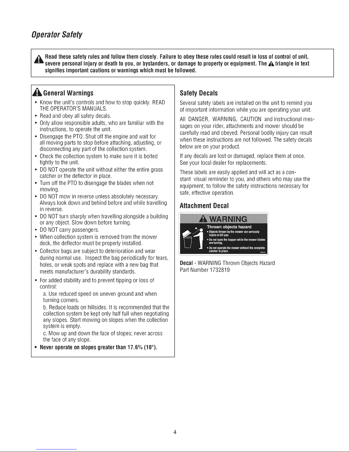
Attachment Decal
Decal- WARNINGThrown ObjectsHazard
PartNumber 1732819
Page 5
Assembly
,_l_ WARNING:Beforebeginning anyservicework turn
off the PTO,set the parking brake,turn off the ignition,
and disconnect the spark plug wire(s).
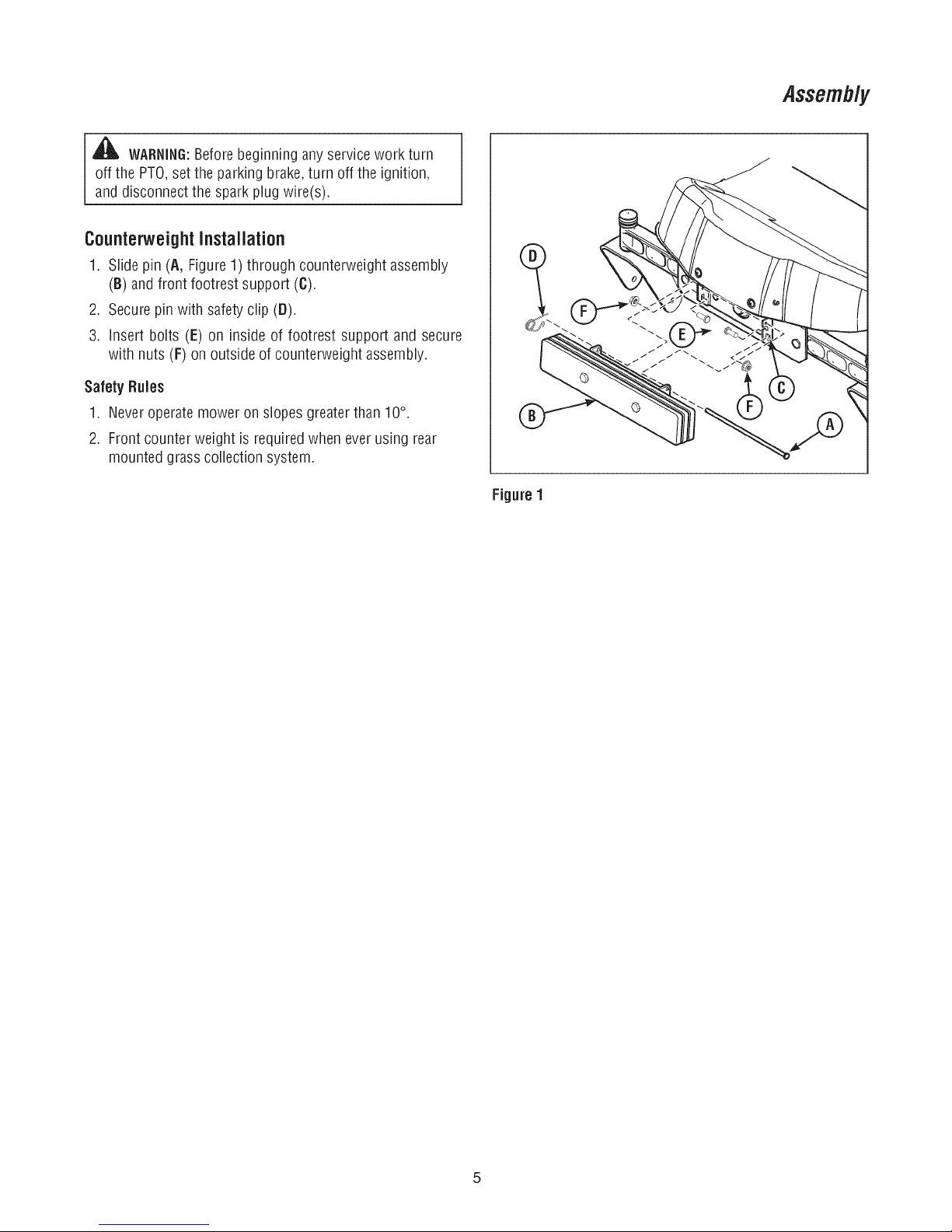
Counterweight Installation
1. Slide pin (A, Figure1) through counterweight assembly
(B) and front footrest support (6).
2. Securepin with safety clip (D).
3. insert bolts (E) on inside of footrest support and secure
with nuts (F) on outside of counterweightassembly.
Safety Rules
1. Neveroperate mower on slopes greater than 10°.
2. Front counter weight is required when ever using rear
mounted grass collection system.
1
Figure 1
Page 6
Assembly
9
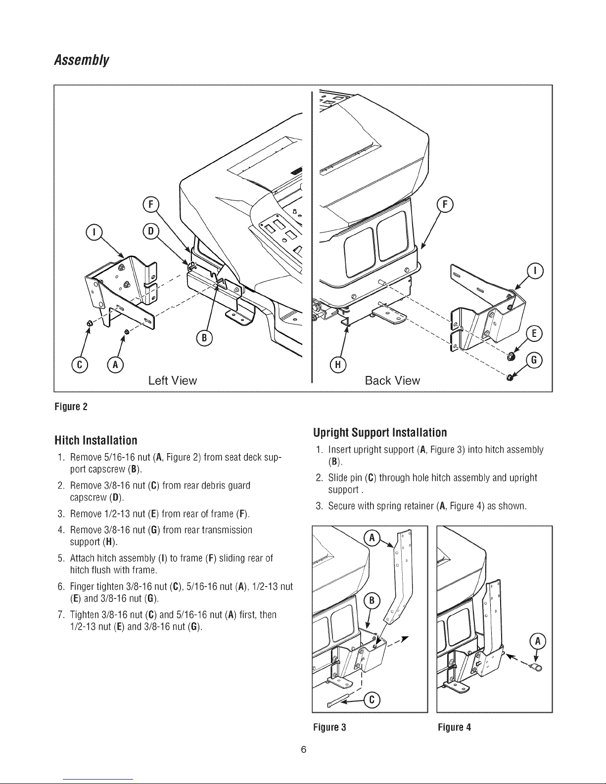
Figure2
HitchInstallation
1. Remove5/16-16 nut (A, Figure2) from seat deck sup-
port capscrew (B).
2. Remove3/8-16 nut (C) from reardebris guard
capscrew(D).
3. Remove1/2-13 nut (E) from rear of frame (F).
4. Remove3/8-16 nut (G) from rear transmission
support (H).
5. Attach hitch assembly (I) to frame(F) sliding rearof
hitch flush with frame.
6. Fingertighten 3/8-16 nut (C), 5/16-16 nut (A), 1/2-13 nut
(E) and 3/8-16 nut (6).
7. Tighten 3/8-16 nut (C)and 5/16-16 nut (A) first, then
1/2-13 nut (E)and3/8-16 nut (6).
Back View
UprightSupport Installation
1. insert upright support (A, Figure3) into hitch assembly
(B).
2. Slide pin (C) through holehitch assemblyand upright
support.
3. Securewith spring retainer (A, Figure4) as shown.
J
Figure 3 Figure 4
Page 7

Assembly
Figure5
CoverInstallation
1. Attach cover assembly (A, Figure5) to bagsupport
bracket(B) using cover hinge pivots (0). Securecover
assemblyto bag support bracketusing hinge pins (D)
and hair pins (E) as shown.
Page 8

Assembly
Tube Assernbiy
AdapterInstallation
1. Removeexisting hardwarefrom wheel bracket (A, Figure
6).
2. Replacewith carriage bolt (B) spacer(C), washer (D)
andsecure with nut (E).
3. Slide lowertube (A,Figure7) underneathdeflector
mounting bracket(B). Side tab (C)of chute fits insidethe
mower deck (D).
Figure 7
Figure 6
4. Rotate latch (A, Figure8) into pocket (B) of hardware
assembly (C}.
Figure 8
Page 9

Assembly
5. Fromthe inside of deck, install 1/4' carriagebolt (A,
Figure9) and secure with a 1/4-20 flange nut (B).
6. Fitthe other side of lower tube (A, Figure 10) onto car-
riage bolt and securewith spacer (B) and knob (C).
Figure 9
Assemble Upper & IVliddieTube
1. Slide the upper tube (A, Figure11) into cover (B)
aligning ridge(C)with cutout (D) as shown.
Figure 11
2. Slide middletube (A, Figure12) into upper tube (B) and
secure with screw (C).
3. Slide middletube (A) over lower tube (D). Fit hole in
strap (E) over pin (F).
Figure 10
Figure 12
Page 10

Operation
Collectorinstallation
1. Mount the hitchand frame assembly (A, Figure 13) onto
reartractor frame.
2. Slidethe uppertube (B) into cover (C) aligning ridge (D)
with cutout (E) as shown.
3. Raisethe cover (C).
4. Attach collector bags(F) using grass baghanger (G) to
bag hangerpost.
Note: It may be necessaryto fold seat forward to allow
cover to stay in the raisedposition.
Figure 13
Attach CollectorBags
1. Raisethe cover (A, Figure14).
2. Attach collector bags(B) using grass bag hanger (C) to
bag hangerpost (D).
Note: It may be necessaryto fold seatforward to allow
cover to stayin the raised position.
Figure 14
10
Page 11

BeforeOperation
Clearthe lawn of all sticks, stones, wire and other debris
which maybe caught or thrown bythe mower blades.
Checkgrass condition, if wet,wait until later in the day.
If grass is wet, the grass catcheris likelyto become
plugged.
Forefficient bagging, air circulation underthe mower
deck,through the chute and into the bag isvery impor-
tant.
Forthis reason, BEFOREYOUBEGINMOWINGyou
should makecertain the underside of the mower and
the underside of the catcherlid arefree from grass and
debris.
Makesure that there is a snug fit between mower deck,
blower housing, tubes, and grass catcher cover.
Operation
Mowingwiththe Catcher
Alwaysoperate with throttle at full speedwhen mowing.
Grassshould becut often, and not too short. If grass istoo
long or lush it maybe necessaryto keepground speedto a
minimum or to cut only half the width of the mower to pre-
vent clogging. If grass is long, operatewith mower in high
cutting position for first pass,cutting againin a lower posi-
tion on a second pass.
Do notopen the coverwith mowerengaged.
If a large amount of cut grass is spilling out from under
deck,the tube may be plugged or the bagsmay be full--
discontinue mowing, stopthe unit, disengagethe PTO,shut
off the engineand then empty the catcher or clearthe tube.
_ WARNING:ALWAYSshut off the tractor. Disengage
the PTO,andallow allmoving parts to stop BEFORE
disconnecting or clearingtube, or emptying catcher.
Beforeleavingthe operator's position for any reason,
engagethe parking brake,disengage the PTO,stop the
engine and removethe key.
To reducefire hazard,keepthe engine, rider and mower
free of grass, leavesand excessgrease.Do not stop
or park rider overdry leaves,grass or combustible
materials.
After Operation
Removeany debris from the screen on the underside of the
lid.
Theblower housing and tube should be removed for clean-
ing.
inspectthe grass bags for wear or damage. Makesure that
there is asnug fit betweenmower deck,blower housing,
tubes, and grass catchercover.
CAUTION:Do not leavegrass in bagger containers.
Emptycontainers after each useand before storing.
Failureto do so may result in spontaneouscombustion
which could develop into afire.
_ CAUTION:Beforeyou begin operating the unit be
certain you havereadall of the safety and operational
information of this instruction sheet, as well asthe
Operator's Manualfor thetractor and anyother
attachments.
NOTE. Neveroperateon slopes greaterthan 17.6% (10°).
11
Page 12

Operation
CollectorRemoval
For operationwithout bagger, the mower deflector MUST
be properly installedin the down position and retainedby
_ CAUTION:Operation WithoutBagger
the spring latch.
1. Lift up cover (A, Figure15), then removeand empty bags
(B).
2. Removehitch and frame assembly (C) from rearof
tractor.
.
Loosenmiddle tube strap from lower tube (D) and
remove middle/ uppertube assembly (E).
4.
Lift discharge deflector (F). Rotatelatch (G) upward on
front of lower chute.
5.
Pull lower chute away from mower.
Figure15
/
/
//
Storage
Storing The GrassCatcher
Cleanthe grass catcherthoroughly using a mild detergent
(other products may damagethe tube). Removeanydebris
from the screenon the undersideof the lid.
If paint has beenscratched on metal parts,touch up with
paint, or apply a thin film of oil to preventcorrosion.
Store in a dry area.Drythoroughly beforestoring for along
period of time. Alwaysstore awayfrom moisture.
12
Page 13

RepairParts
PTS - 1
Page 14

2-Bin Bagger Group - 52 inch 107.249130
NOTE: Unless noted otherwise,
use the standard hardware torque
specification chart.
Assemble
6, 43, 57, 66
43
\
34
\
Support
Ref
15
49
53 26
Assemble
4, 36, 39, 44 /,
47, 52, 56, 61,63 /
7 36
44 10
47
\
Assemble
10, 14, 17,31,32,
45, 46, 55
32
14
\
52" Mower Housing
PTS - 2
Page 15

2-Bin Bagger Group - 52 inch 107.249130
REF NO PART NO. QTY.
1 004X24MA 3
2 004X71MA 1
3 7036433SM 1
4 054407ZMA 2
5 054416ZMA 1
6 054537MA 1
7 054563MA 1
8 1734190ASM 1
9 1931317SM 1
10 1672023ASM 2
11 1960685SM 1
12 7036404SM 1
13 1734229SM 1
14 1703764SM 2
15 2176012SM 2
16 1737764AYP 1
17 1703807ASM 2
18 1738033YP 1
20 1737844AYP 1
21 1960044SM 1
22 1922130SM 2
23 1734191ASM 3
24 7200008SM 1
25 310088MA 2
26 1734776YP 1
27 ..... 1
28 ..... 1
29 1737838AYP 1
31 1733491SM 2
32 1733709SM 2
34 1733885SM 1
36 1734223YP 1
37 1734299SM 1
39 1736026YP 1
43 1736656YP 1
44 1736886AYP 2
45 1917356SM 4
46 1917372SM 4
47 1918196SM 2
48 1927557SM 2
49 1723244SM 1
DESCRIPTION
SCREW, Truss-Head, 1/4-20 x 1/2"
SCREW, Truss-Head, 1/4-20 x 1"
MOUNT, Strap
PIN, Cover Hinge
HANDLE CONNECT, Tube
HNADLE, Plastic
PIN, Latch
BRACKET, Front Weight Mount
BOLT, Carriage, 1/4-20 x 3/4"
CLAMP, 1/2" Diameter Rod
NUT, Conical, 25-20
NUT,Weld, 10-24
PIN, Hinge
BAG, Grass 15.9 X 16.5
RETAINER, Spring
UPSTOP, Deflector
HANGER, Grass Bag
TRIM, 31-1/2"
HITCH, Bagger
WASHER, 5/16, 1-1/40D
CAPSCREW, Hex-Head, 3/8-16 x 2-1/4"
WEIGHT, Counter
ROD, Seat Hinge
BOLT, Shoulder, .250X.312.25
BOOT, Bagging, 46/52 Mower
MYLAR OVERLAY, ID Sticker
ID STICKER
BRACKET, Upright Mount
HOOP, Twin Catcher, 1/2" Diam.
EDGING, 12"
ELBOW, Upper Tube
SUPPORT, Upright
TUBE, Clear
CROSS SUPPORT, Twin
COVER ASSEMBLY, Twin Bagger
PIVOT, Hinge
LOCKWASHER, Spring, 5/16
NUT, Hex, 5/16 x 18
PIN, Quick
NUT, Hex-Flange, 5/16
SPACER
Footnotes
PTS - 3
Page 16

2-Bin Bagger Group - 52 inch 107.249130
NOTE: Unless noted otherwise,
use the standard hardware torque
specification chart.
Assemble
6, 43, 57, 66
43
\
34
\
Support
Ref
15
49
53 26
Assemble
4, 36, 39, 44 /,
47, 52, 56, 61,63 /
7 36
44 10
47
\
Assemble
10, 14, 17,31,32,
45, 46, 55
32
14
\
52" Mower Housing
PTS - 4
Page 17

2-Bin Bagger Group - 52 inch 107.249130
REF NO PART NO. QTY.
50 1737765AYP 1
51 1708511SM 1
52 1928352SM 10
53 1928372SM 4
54 1930642SM 2
55 1931333SM 6
56 1931349SM 8
57 1933896SM 2
58 1921333SM 1
59 1960223SM 1
61 1960252SM 5
63 1960294SM 6
66 1960404SM 3
69 2171600SM 1
70 7026257MA 1
71 1960698SM 1
72 1738295YP 1
73 7091627YP 1
DESCRIPTION
LATCH
SPACER
NUT, Hex-Flange, Whiz, 3/8-16
NUT, Hex-Flange, 1/4-20
NUT, Hex-Flange, Top-Lock, 1/4-20
BOLT, Carriage, 5/16-18 x 3/4"
BOLT, Carriage, 3/8-16 x 7/8"
NUT, Hex-Lock, Nylon-Insert, 10-24, 1/4-20
BOLT, Carriage, 5/16-18 x 1, G5
BOLT, Carriage, 5/16-18 x 1-1/4, G5
BOLT, Carriage, 1/4-20 x 5/8"
NUT, Hex-Flange, Whiz, 1/4-20
SCREW, Truss-Head, Phillips, 10-24 x 3/4"
STRAP, HOOD, Black Rubber
WASHER, Wave
BOLT, Carriage, 1/4-20 X 1, G5
KNOB, 5-Point, 1/4-20
WASHER, Flat, 9/32 X 1
Footnotes
PTS - 5
Page 18

Hardwareidentification& TorqueSpecifications
Common Hardware Types
Hex Head Capscrew
Carriage Belt
€(((((((((((((((((((0
Standard Hardware Sizing
When a washer or nut is identified as 1/2", this is the
Nominal size, meaning the inside diameter is 1/2 inch; if a
second number is present it represent the threads per inch
When bolt or capscrew is identified as 1/2 - 16 x 2", this
means the Nominal size, or body diameter is 1/2 inch; the
second number represents the threads per inch (16 in this
example, and the final number is the body length of the
bolt or screw (in this example 2 inches long).
The guides and ruler furnished below are designed to
help you select the appropriate hardware and tools.
m_
Washer
Leckwasher
O Hex Nut
Nut, 1/2"
Inside
- ¢o
Diameter
m_
Screw, 1/2 x 2 I
m_
m_
m_.o
od,J I
Diameter I B°dy_____. |/
_ength _
__@
Torque Specification Chart
FORSTANDARD MACHINE HARDWARE (Tolerance _+20%)
_raarddeware G 0 Q
SAEGrade2 SAEGrade5 SAEGrade8
Size Of in/Ibs in/Ibs
Hardware ft/I bs ft/Ibs Nm.
8-32
8-36
10-24
10-32
1/4-20
1/4-28
5/16-18
5/16-24
3/8-16
3/8-24
7/16-14
7/16-20
1/2-13
1/2-20
9/16-12
9/16-18
5/8-11
5/8-18
3/4-10
3/4-16
7/8-9
7/8-14
1-8
1-12
1. These torque values are to be used for all hardware
excluding: Iocknuts, self-tapping screws, thread forming
screws, sheet metal screws and socket head setscrews.
2. Recommended seating torque values for Iocknuts:
a. for prevailing torque Iocknuts - use 65% of grade 5
torques.
b. for flange whizlock nuts and screws - use 135% of
grade 5 torques.
3. Unless otherwise noted on assembly drawings, all torque
values must meet this specification.
Nm. ft/Ibs Nm.
19
20
27
31
66
76
11
12
20
23
30
35
50
55
65
75
102.0 120 163.2
90
122.4 150 204.0
100
136 180 244.8
160
217.6 260 353.6
180
244.8 300 408.0
140
190.4 400 544.0
155
210.8 440 598.4
220
299.2 580 788.8
240
326.4 640 870.4
in/Ibs
2.1 30 3.4
2.3 31 3.5
3.1 43 4.9
3.5 49 5.5
7.6 8 10.9
8.6 10 13.6
15.0 17 23.1
16.3 19 25.8
27.2 30 40.8
31.3 35 47.6
40.8 50 68.0
47.6 55 74.8
68.0 75 102.0
74.8 90 122.4
88.4 110 149.6
NOTES
41 4.6
43 4.9
60 6.8
68 7.7
12 16.3
14 19.0
25 34.0
27 34.0
45 61.2
50 68.0
70 95.2
80 108.8
110 149.6
120 163.2
150 204.0
170 231.2
220 299.2
240 326.4
386 525.0
420 571.2
600 816.0
660 897.6
900 1,244.0
1,000 1,360.0
Wrench & Fastener Size Guide
1/4" Bolt or Nut
Wrench--7/16"
5/16" Bolt or Nut
Wrench--I/2"
3/8" Bolt or Nut
Wrench--9/16"
PTS - 6
7/16" Bolt or Nut
Wrench (Bolt)--5/8"
Wrench (Nut)--11/16"
1/2" Bolt or Nut
Wrench--3/4"
Page 19

Briggs & Stratton Yard Power Products Group
Copyright © 2009 Briggs & Stratton Corporation
Milwaukee, Wl USA. All Rights Reserved
 Loading...