

Page 1
OPERATING
INSTRUCTIONS
AND
PARTS
CRAFTSMAN DRILL
MODEL NUMBER
The
model number
base
near
the
us
regarding your
of
your
column. Always mention this number when communicating with
Drill
Press,
HOW TO
All
parts listed herein
or
SIMPSONS-SEARS LIMITED. When
order house which
furnished
be
WHEN ORDERING
billed
on
request
accordingly.
INFORMATION
1.
The
PART
NUMBER.
2. The
PART
NAME.
serves
or
REPAIR
AS
SHOWN
4. The
may be
the
parts
3. The
103.24521 & 103.24531
Drill
Press
or
when ordering
ORDER
ordered through
territory
will
be
PARTS,
IN
MODEL NUMBER.
NAME
LIST
will
be
found
REPAIR
SEARS,
ordering
in
which
you
shipped
THIS
at
ALWAYS GIVE
LISL
of
item.
FOR
PRESS
on a
plate located
parts.
PARTS
ROEBUCK
parts
by
mail from
live,
selling prices
prevailing prices
THE
103.24521
103.24531
DRILL
PRESS
on the
AND CO.
the
mail
will
be
and you
FOLLOWING
or
will
FOR
SEARS,
IN
CANADA,
COAST
TO
COAST
SERVICE
NATION-WIDE
FROM
SEARS
YOUR CRAFTSMAN POWER TOOLS
SEARS,
SIMPSONS-SEARS
back
pert mechanical service
CRAFTSMAN
If
call
this
ROEBUCK
SIMPSONS-SEARS
RO EBUCK
up
your investment with
and
when
on us to
fine piece
AND
AND CO. and
LIMITED
and
replacement parts.
you
need repairs
protect your investment
of
equipment.
CO. - U.S.A.
LIMITED
in
Canada
quick,
genuine
or
service,
ex-
in
SOURCE
FORM 27979-5AB
Lithographed
in
U.S.A.
Page 2
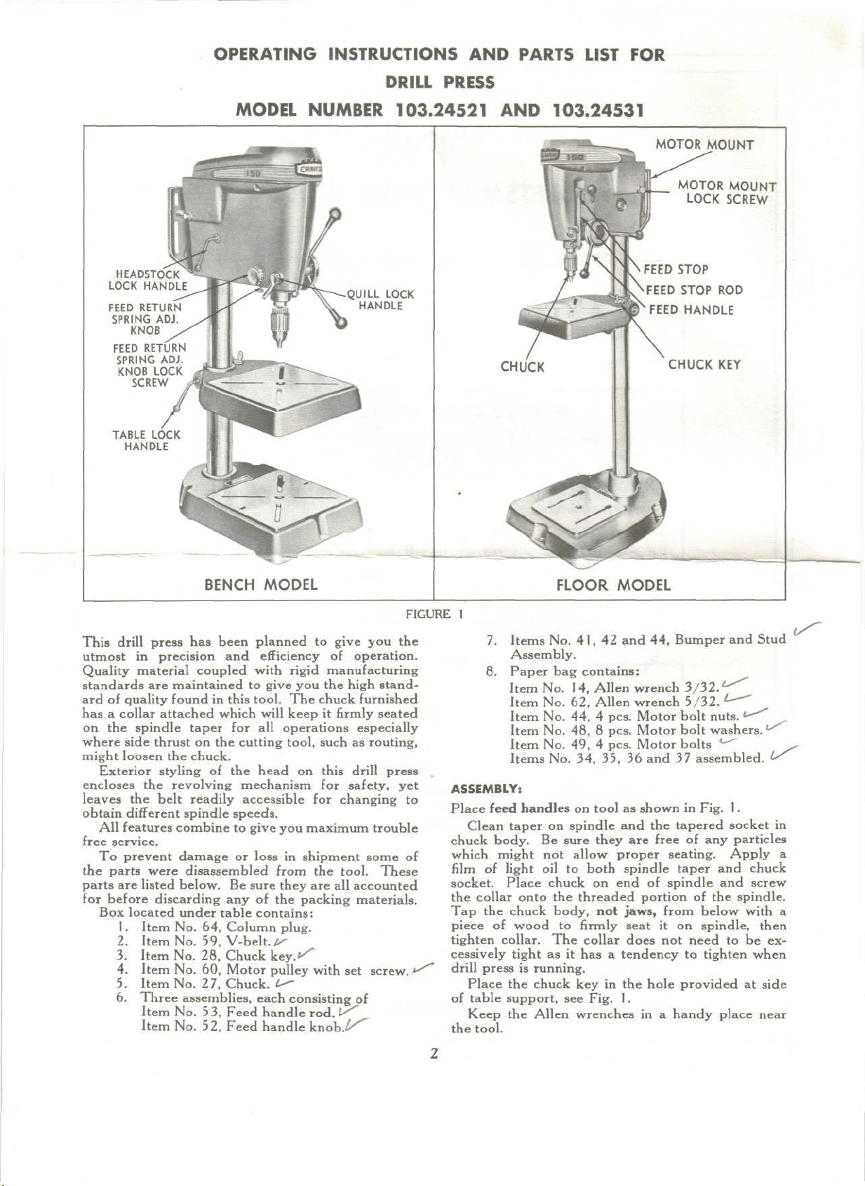
OPERATING
INSTRUCTIONS
DRILL PRESS
AND
PARTS LIST
FOR
HEADSTOCK
LOCK
HANDLE
FEED
RETURN
SPRING
ADJ.
KNOB
FEED
RETURN
SPRING
KNOB
LOCK
SCREW
TABLE
LOCK
HANDLE
ADJ.
MODEL
NUMBER
HANDLE
103.24521
LOCK
AND
CHUCK
103.24531
MOTOR
FEED
FEED
FEED
MOUNT
MOTOR
LOCK
STOP
STOP
HANDLE
CHUCK
MOUNT
SCREW
ROD
KEY
This
drill press
utmost
in
precision
BENCH
has
been planned
and
MODEL
to
efficiency
Quality material coupled with rigid
standards
ard of
has a
on the
where side thrust
might
Exterior
encloses
leaves
obtain
All
free
To
the
parts
for
before discarding
Box
are
maintained
quality
found
collar attached which
spindle taper
on the
loosen
the
chuck.
styling
the
revolving mechanism
the
belt readily accessible
different
features
spindle
combine
to
in
this tool.
will
for all
cutting tool, such
of the
head
speeds.
to
give
service.
prevent damage
parts
were
disassembled
are
listed below.
or
Be
loss
sure they
any of the
located under table contains:
1.
Item
2.
Item
3.
Item
4.
Item
5.
Item
6.
Three
No. 64,
No.
No. 28,
No. 60,
No.
assemblies, each
Item
No. 53,
Item
No. 52,
Column plug.
59,
V-belt.A Chuck
Motor pulley
27,
Chuck,
Feed handle rod.
Feed
give
you the
The
keep
operations especially
on
for
you
maximum trouble
in
shipment some
from
the
packing materials.
key."''
l^
consistingj>f
handle
give
you the
of
operation.
manufacturing
high stand-
chuck
this
for
furnished
it firmly
as
drill
safety,
seated
routing,
press
changing
tool.
These
are all
with
accounted
set
screw.
FIGURE
yet
to
of
FLOOR
1
7.
Items
8.
Paper
ASSEMBLY:
Place
feed
Clean taper
chuck
body.
which
might
film
of
light
socket. Place chuck
the
collar onto
Tap the
piece
chuck body,
of
tighten collar.
cessively tight
drill
press
Place
the
of
table support,
Keep
the
the
tool.
No. 41, 42 and 44,
Assembly.
bag
Item
No. 1 4,
Item
No. 62,
Item
No. 44, 4
Item
No. 48, 8
Item
No. 49, 4
Items
No. 34, 35, 36 and 37
handles
on
spindle
Be
sure they
not
allow proper seating. Apply
oil to
the
wood
to firmly
The
as it has a
is
running.
chuck
see
Allen wrenches
MODEL
Bumper
contains:
Allen
wrench
Allen wrench 5/32.
pcs. Motor bolt nuts.
pcs. Motor bolt washers.
pcs. Motor bolts
on
tool
as
shown
and the
are
both
spindle
on end of
threaded portion
not
jaws,
seat
collar does
tendency
key in the
Fig.
1.
in a
in
tapered socket
free
of any
taper
spindle
from
it on
not
need
to
hole provided
handy place near
and
Stud
3/32.
*•
assembled.
Fig.
1.
particles
and
chuck
and
screw
of the
spindle.
below with
spindle, then
to be ex-
tighten when
at
side
^
in
a
a
Page 3

INSTALLATION:
Three 1 3/32 inch diameter holes
vided
in the
base
through which bolts
be
inserted
structed bench
To
screws, Fig.
moved.
the
bolts, nuts,
motor mou nt
portion
if
your moto r
rect, place motor
is
on the
spindle must
end of
Mount
so
that
speeds,
be in
pulley,
Tighten
wrench,
it,
position
tighten
Place
excessively,
tool.
Tighten
maintain
Adjust
the
motor
to
secure
or
tool
the
stand.
install motor loosen
1,
unti l
the
motor mount
Fasten
of the
the
motor
and
washers provided
is
reinstalled
mount will
has a
on
l eft
side. Direction
be
clockwise when viewed from pulley
be
switch,
motor moun t
spindle.
the
motor pulley,
the
small diameter
the
largest groove
line with
No.
1.
the
pulley
No. 62. If
the
against
belt around
by
the
pulley
the flat.
sliding
the
on the
smallest
set
screw with
your motor
so
the
the
motor mo unt lock screws
this tension.
the
screw,
is
parallel with
No. 42,
drill
the
to the
on the
down.
and
No. 60, on
is at
groove
that
pulleys
motor mount away
until
the
have
been
or
screws
press
to a
well con-
motor mount
may be re-
m otor mount with
so
that when
tool,
the
For
convenience,
rotation
of
will
so
that
rotation
the
motor
bottom.
For
motor pulley should
on the
the
larger Allen
shaf t
has a flat on
the set
and
tighten,
the
center line
screw will
center line
column.
MOTOR:
A
4 /£
horsepowei^475Q
will
provide
drill
press
s uffic ient
on
duty operation
general work.
a 1
R.P.M^baH
speed
/2
horsepower motor
and
power
For
continuous heavy
bearing
for
is
mended.
SPEED:
The
spindle speeds obtainable with these 4 step pul-
leys
are
shown
SPINDLE
R.P.M.
5000
2390
1280
610
3970
1730
771
2905
1050
in
MOTOR
MOTOR
Fig.
DRILL
PRESS
P UL LEY
PULLEY
FIGURE
2.
RAISED
RAISED
2
ONE
TWO
MOTOR
(1750
R.P.M)
GROOVE -/
GROOVES-'
pro-
may
lock
larger
be
cor-
switch
of the
s haft
normal
spindle
not
fro m
to
of
of the
mutor
your
recom-
I
|
For
slower speeds
available
from
order house.
Ask for
use a
your nearest Sears retail store
Catalog
LUBRICATION:
The
spindle
with
lubricant
for
the
Place
shaft,
No. 54. The oil
on
trie
To
maintain smoothness
vent
rust,
light
cup
tion.
With
backside
below
and
pulley bearings have been packed
and
l ife
a few
of the
will require
bearing.
drops
of oil
occasionally
hole
right han d side
of the
occasionally apply a small amount
grease
of the
the
to the
quill
head
pulley,
quill
still
f ull y
and
apply grease
and to the
extended, reach into
quill.
Occasionally
with
an oil
smooth
sliding action.
wipe
soaked
the
rag to
co lumn,
prevent rust
CONTROLS:
The
chuck
is a
key-type
inch
diameter.
retain
it on the
sity
of
having collet chucks
It is
spindle. This eliminates
velop side thrust while
The
feed stop
unit
and has a
equipped with a lock collar
in
operation, such
provides a means
hole depths bef ore drilling
holes
to the
The
the
feed
as an
assembly,
fast
positioning
and
sliding
The
be
adjusted
CAUTION:
never
be
the
feed
made.
within
adjust
The
1/16
inch graduations, carrying
same depth.
lock screw,
stop collar,
it up or
feed
stop
to the
The top of the
more than
stop collar
If the
the
the
desired
J/g"
allowance, reposition
feed
stop
feed stop
No. 36,
No.
37,
can be
by
adj ust ing
moved
turning
down
to an
collar,
exact depth desired.
J/s"
away
after
an
ad just ment
ad jus tin g
rod is a
gauge, with 5 inches
lock nut.
The
feed handle
chuck 4 inches.
return
action.
The
quill lock handle when tight holds
at any
depth
routing,
quill
lock befo re changing position
The
control
of cut for
surface
table
lock handle
the
barrel locks which grip
When releasing either
care.
Support
it
will
not
drop
is
used
It has an
automatic spring loaded
such operations
grinding, etc. Always release
and
of
these handles
the
part
too
you
rapidly causing damage
tool.
The
feed return adjusting knob controls
tension
make
hinge
allow quicker belt changes.
one
ward
The
on the
motor
the
feed
mount
changing
action incorporated
pulley groove
and
slip
the
belt into
lever.
has
been hinged
of
spindle
in
To
to
another, pivot
the
Multi-Speed
Attachment
or
No.
9A-2338.
no
is
located
f urth er
att entio n
on the
pinion
in the hub
head.
of
operation
while
upper portion
for
such tools that
or for
when
in
place.
on the
the
unit a quarter turn
approxim ate
and to
in a
down posi-
to the
spindle,
of the
table
and
and
m aintain
capacity
of
the
as
routers.
of
presetting
0-1
neces-
drilling several
tightened,
The two
stop
holds
pieces,
rod for
pr.aifir.ri,
No. 34, can
adju sting collar should
fr om
the
a djus tme nt
can not be
shoulder
has
the
unit
been
made
collar.
the
feed
stop
to
raise
and
lower
the
as
shaping,
of
quill.
headstock lock handle
the
column.
do so
wish
to
a dju st
so
to the
the
spring
in
order
speeds
easier.
The
this motor mou nt
move
the
belt
fr om
the
motor for-
desired
grooves.
mail
pre-
of
the
base
/ 2
to
de-
then
of
and
of
and
the
quill
the
with
that
to
will
Page 4

ADJUSTMENTS:
The
followi ng
keep
your
If
the
chuck
to the top of the
becomes
follows;
using
Lock
the
adjusting knob
adjusting
ing
kn ob counter-clockwise
screw. Release
chuck
down.
repeat
the
adj ustme nts
drill
press
automatic
sluggish,
quill
feed
the
the
chuck
lock handle.
firmly
knob lock screw, Fig.
the
If
spring tension
above
a dju s tmen t
may be
at its
most
return
stroke
tension
or if the
may be
at the top of its
Hold
and
release
and
quill
lock handle
until
necessary
eff icient
fails
to
r et ur n action
adjusted
the
feed return
the
feed return
1.
Turn
re-tighten
and run the
is
still
not
it is.
to
operation.
r eturn
the
as
stroke
the
adjus t-
the
lock
sufficien t
sive
commercial operations
high
speed
steel drills alth ough more expensive,
prove
to be the
are
possible plus longer
The
solid center wood
ing
aro und a solid center
better tool
The fluted bit is an
bit.
It has two flutes
edge
and
spur.
The
best
bit for
wood
is the
spur machine bit.
tracks nicely
and
produces
hole.
For
larger holes, a hole
metal
or
wood. This
and
teeth around
the
blade.
Also,
for
large holes
may
be
used. When
wood
bit is
must
have
will
not
may be filed
Countersinking
plished
the
cleanest
tinuous
used
the
threads removed
enter
the
o ff. (See Fig.
by
using
cut and
operation.
in the
wood
in
the
cutt ing
excellent
each
high
qual ity
bit has a
outer
in
the
expansion
drill
too
wood
double
will
are to be
as
higher operating speeds
edge
bit has a
but
carries
ter min ating
machine
It is the
an
exceptionally smooth
saw is
available
center drill
rim
wood
pe rfo rmed,
life.
single
flute
two
spurs.
all
purpose wood
in a
drilling
stif fe st
for
for
similar
an
to a saw
expansion
bit or any
press,
the
screw point
f rom
it so
rapidly.
These
3.)
may
best
be
accom-
lip
style.
It
will
not gum up
u nder con-
will
tur n-
cutting
in
drill,
either
pilot
bit
hand
that
it
threads
give
FIGURE
To
change
or
headstock lock handle (Fig.
and
rotate table
Item
51 ,
180°.
the
locked position
lock,
Re-insert
CAUTION: Headstock
be
securely supported when changing locked position
of
handles.
The
Quill Lock Handle, (Fig.
of
operation should point
change
screw,
tate
set
the
mount
ens
the
to
the
position
of the
remove handle
to
correct position. Replace handle
screw.
Belt
tension
adj ustment
motor moun t lock screws
away
fro m
the
tool. Excessive tension short-
bearing
motor
prevent slippage
life,
causes excessive belt wear
of
power. Tension should
at
3
of
table lock h andle
1) ,
remove handle
item
67, or
and
or
headstock lock,
tighten lock handle.
table assembly should
1 ) for
down
when locked.
handle, loosen
fro m
hex
head screw
is
made
and
by
moving
be
normal operating
greatest ease
the set
and ro-
and
tighten
loosening
the
motor
and
just
enough
speeds
feeds.
Tighten pulley
set
screws
af ter
a few
hours
operation.
TYPES
OF
BITS:
A
variety
of
bits
are
available
for use in
your drill
press.
For
metal
prove adeq uate
drilling
for the
the
standard twist drill will
home
-work
shop.
If
exten-
To
robs
and
Length
of
Cutting
must
be
e quo t
DRILL
SHARPENING:
When grind in g twist
efficiency
cised.
tained,
length,
center
should
included,
cluded,
gradually
ance
of the
The
dead
that
is, the
Fig.
4.
line
of the
be
approximately
for
for
wood.
behind
at the
heel
drill,
center
Also
drill
metal
The
the
is
OPERATION:
Chuck
removal;
If
at any
time
you
loosen
the
it.
This
Do not
you
chuck holding collar
will
force
may
att empt
damage
to
the
the
lips
FIGURE
drills,
4
in
extreme
of the
order
care
point must
cutting lips must
their angle
must
and 35
cutting
cutti ng
about
1 2
wish
to
60
in
be
equal.
degrees,
degrees,
lip
edge
degrees.
remove
should
and
chuck
drive
spindle
or
from
wedge
or
bearings.
the
Heel
of
Cutting
Lip
to
maintain
should
be
be
be the
relation
The
12 0
70
degrees
be
so
that
the
the
chuck merely
continue
spindle taper.
the
chuck
the
exer-
main-
same
to the
angle
degrees
in-
relieved
clear-
to
turn
off as
Page 5

For
extensive
table
of
34
inch plywood will
added work area
of
you r work . Fasten
press
table with
table
also provides a good
shaping
It
drills
material
ing
reverse
through
hole,
fen ce,
af f o r d s
protection
break through
When
drilling
un der
and
mutila tio n
Another
metho d
the
work piece when
and finish the
For
drilling
the
f eed
pivot pins
the
to a
stop nut s
use on
woodworking,
prove
and the
counter sunk
the
prote ction
the
plywood table
screws. This
surface
and
for the
drill press table when
work piece.
from
for
other similar units.
through wood, a piece
work piece
as the
of
pr eserving
hole
d efinite
will
eliminate splinter-
drill p oint breaks through.
the
surf ace
the
point
of
f rom
opposite side.
depth,
such
may be set to the
an
auxiliary
its
worth
shi fting
to the
drill
auxiliary
mou nting
of
scrap
is to
drill breaks
as a
blind
desired
in
a
depth
by
lowering
of
the
work
piece
hole desired.
A
straight piece clamped
or
fence,
has
the
same distance
grooving,
many uses,
fluti ng
or
SAFETY:
The
work piece should
table, either
its
turning with
pensive
and is
work.
The
be
used
work
piece
by
clamps, pins,
the
means
readily
for
of
adaptable
drill
vise
cylindrical work.
as it may
the
drill
to a
mark
on the
corresponding
to the
as in
from
an
edge
to the
table,
drilling
or as a
several holes
milling.
be
held securely
or a
vise,
to
drill. A drill
vise
is an
hol ding many varieties
for use
or a
V-block
In
break drills
with cylindrical
should always
any
case secure your
and fly off the
depth
as a
guide
on the
prevent
of
edge
of
guide
for
inex wo rk
table.
Key
No.
1
2
3
4
5
6
7
8
9
10
1 1
12
13
14
1 5
16
17
18
19
20
21
22
23
24
25
26
27
28
29
30
3 1
32
33
34
35
36
37
Part
No.
27415
18413
18212
18414
18415
27727
38617
27217
18604
38632
18512
18120
*X-18I
*X-1407
27623
38628
1851
18410
18429
18422
182
I I
27625
27813
*X-277
38422
27130
38623
**I8I29
*X-413
*X-420
*X-605
27812
27627
27631
38881
27628
27629
PART NAME
Spindle
Pulley
Spindle & Pulley
Pulley
Ball
Inner
Snap Ri ng
Outer Snap Ring
Panel
Panel
Screw
Drill
Head Frame
Hand
Knob
Quill
Lock Sleeve
Quill Lock
-Lock
Hand le
Set
Screw
Allen Wrench 3/ 32
Lock
Handle
Head Lock Sleeve
Knob
1
Lock Screw
Spindle
C ollar with
Washer-Rubber
Washer
Quill
Bearing
Quill
Quill
Gasket
Cap
Screw
Feed
Stop
Spindle
Ass'y.
Chuck
Chuck
Key
Hex
Nut
Hex
Lock
Snap
Feed Stop
Feed
Spring
Lock
Feed
Jam
Nut
"4-20
Washer
Ring
Stop
Screw
Stop Collar
Sleeve
Bearing
Screw
aiuLSei
No.
"4-20
Bracket
J4
Rod
Adjusting Collar
Screw
1 0 -24 x %Soc.
Set
Screw
x 1
J/2 Hex
^-16
Amer.
Std.
Head Cone
Head
PARTS
Pt.
LIST
Key
No.
38
39
40
41
42
43
44
45
46
47
48
49
50
5 1
52
53
54
55
56
57
58
59
60
61
62
63
64
65
66
67
68
69
70
71
72
Part
No.
*X-170
18513
18421
27814
27632
38790
*X-417
38460
38876
38692
*X-601
*X-309
X-205
38629
18916
27626
27310
18915
27617
38631
*X-565
**X-1467
38390
»X-3609
'X-1400
27219
27717
38633
38627
38626
27621
27622
27340
27350
38211
*X-185
27104
27979
PART
NAME
Set
Screw
5/ I 6 - 1
8 x
Pinion Shaft Retaining Screw
Washer
Fibre
Bumper
Threaded Stud
Motor
Support Base
Hex Nut
Motor
Roll
Rod Plain
Mack.
Cap
Head
Feed Handle Knob
Feed Handle
Hub,
Feed Return Spring
Pin
Quill Lock
Mach.
V-Belt
Motor
Set
Allen
Table
Column
Lock
Table
Table Lock
Column
Column
Base
Base
Base
Set
Spindle Pulley Ass'y.
Instruction
5/16 -18
Mount
Pin
Motor Support
Washer
Bolt
57 1
Screw
5 / lb -1 8- %
Lock
Rod
Pinion, Sprin g
Screw
No.
1/2
x 45
Pulley with
Screw
5 / 1 6- 18 x '/2 Soc. Head
Wrench
Plug
Handle
Lock Sleeve
for
Model
for
Model
for
Model 1 03. 24 5 2 1 only
for
Model
Lock Shoe
Screw
^/i~
Sheet
Y2 Soc.
Ass'y
Complete
1 I
/ 3 2 I.D.
6-18i-LSquare
8- 32 x %
inches long
5 /32
103 .24 531
I 3 x 1 ^ Square Head
and
x I I
Hex. Head
& Pin
Set
Screw
1 0 3 . 2 4 5 2 1
1 0 3 . 24531
Parts
Hd.
/ 1 6 O.D.
Ass'y.
Rd.
only
only
only
List.
Cone
Head
Head
Pt.
This
The
*Items
houses.
sheet
parts
'Standard
are
regu lar stock
May
is
intended
shown
and
hardware
also
for
listed
For
Illustration—See
in
be
ordered
instruction
may
include
page
6
items—may
Sears h ardware departments
as
repair
and
accessories
repair
be
purchased
parts
parts
not
by
part number provided.
only
and is not a
necessarily
locally.
and
mail order
part
packing
of
this
slip.
tool.
Page 6

—72
SPINDLE
ASS'Y.
PULLEY
45
MOTOR
INCLUDES
MOUNT
COMPLETE
ITEMS
41
ASS'Y.
THRU
49
 Loading...