

Page 1
OPERATING INSTRUCTIONS
AND PARTS LIST FOR
CRAFTSMAN
JOINTER
4_/_INCH
Model Number 103.23340
This is the model number of your Jointer. It will be found
on a platelocated on the right side of the front table,
Always mention this model number when communicating
with us regarding your Jointer or when ordering parts.
......................HO'4V TO ORDER REPAII-4 PARTS _ -
All parts listed herein may be ordered through Sears, Roebuck
and Co. or Simpsons-Sears Limited. When ordering parts by mail
from the mail order house which serves the territory in which you
live, selling prices will be furnished on request or parts will be
shipped at prevailing prices and you will be billed accordingly.
WHEN ORDERING REPAIR PARTS, ALWAYS GIVE THE FOL-
LOWING INFORMATION AS SHOWN IN THIS LIST:
1. The PART NUMBER.
2. The PART NAME.
3. The MODEL NUMBER.
4. The NAME of item.
This list is valuable. It will assure your being able to
obtain proper parts service. We suggest you keep it with
other valuable papers.
SEARS, ROEBUCK and CO.--U.S.A.
SIMPSONS-SEARS LIMITED--CANADA
LITHOGRAPHED IN U. S.A.
SOURCE FORM 29939
Page 2
OPERATING INSTRUCTIONS AND PARTS LIST FOR
MODEL NUMBER 103.23340
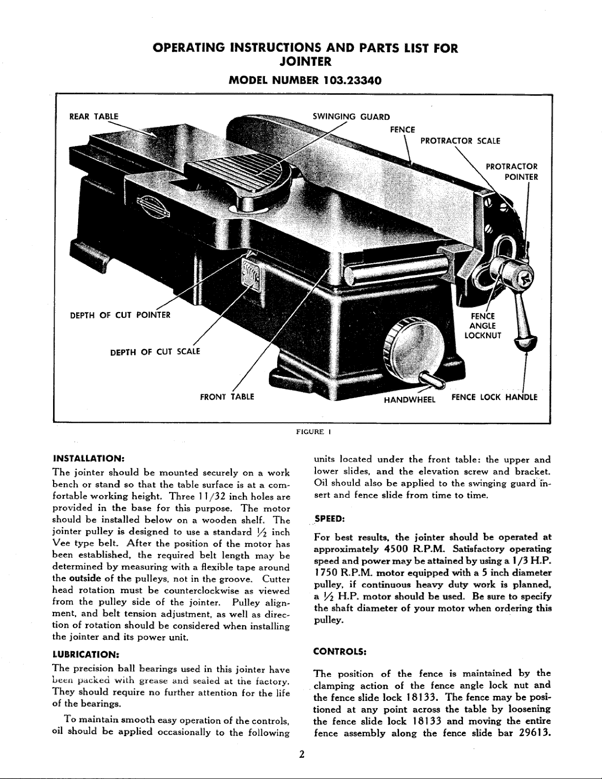
REAR TABLE
DEPTH OF CUT POINTER FENCE
DEPTH OF CUT SCALE
FRONT TABLE
SWINGING GUARD
FENCE
PROTRACTOR SCALE
ANGLE
HANDWHEEL FENCE LOCK HANDLE
PROTRACTOR
POINTER
INSTALLATION:
The jointer should be mounted securely on a work
bench or stand so that the table surface is at a com-
fortable working height. Three 11/32 inch holes are
provided in the base for this purpose. The motor
should be installed below on a wooden shelf. The
jointer pulley is designed to use a standard ]/_ inch
Vee type belt:. After the position of the motor has
been established, the required belt length may be
determined by measuring with a flexible tape around
the outside of the pulleys, not in the groove, Cutter
head rotation must be counterclockwise as viewed
from the pulley side of the jointer. Pulley align-
ment, and belt tension adjustment, as well as direc-
tion of rotation should be considered when installing
the jointer and its power unit.
LUBRICATION:
The precision ball bearings used in this jointer have
beet_ packed with grease slid sealed at the factory.
They should require no further attention for the life
of the bearings.
To maintain smooth easy operation of the controls,
oil should be applied occasionally to the following
FIGURE I
units located under the front table: the upper and
lower slides, and the elevation screw and bracket,
Oil should also be applied to the swinging guard ih-
sert and fence slide from time to time.
SPEI:D:
For best results, the iointer should be operated at
approximately 4500 R.P.M. Satisfactory operating
speed and power may be attained by using a I/3 H.P.
1750 R.P.M. motor equipped with a 5 inch diameter
pulley, if continuous heavy duty work is planned,
a _ H.P. motor should be used. Be sure to specify
the shaft diameter of your motor when ordering this
pulley.
CONTROLS:
The position of the fence is maintained by the
clamping action of the fence angle lock nut and
the fence slide lock 18133. The fence may be posi-
tioned at any point across the table by loosening
the fence slide lock 18133 and moving the entire
fence assembly along the fence slide bar 29613.
Page 3

The fence lock handle is designed so that it may be
disengaged after use on the lock nut and will hang
in a neutral position as shown. The angle between
the fence and the table may be changed for beveling
operations by loosening the fence angle lock nut. The
angle selected for the bevel cut is indicated on the
protractor scale. After changing the fence position
as described above, check carefully that the fence
angle lock nut is secure before proceeding with a cut-
ting operation.
The handwheel when turned will raise or lower the
front table, thus regulating the depth of cut as in-
dicated by the depth of cut pointer and scale.
ADJUSTMENTS:
If at any time the cut obtained should vary from that
indicated on the depth of cut scale the following
adjustment may be made. Set the front and rear
tables at the same level and check with a straight-
edge. Loosen the screw X2951 holding the pointer
29719, and shift the pointer until it indicates zero
on the scale. Tighten the screw securely after making
the above adjustment°
If a 90 ° setting of the fence angle protractor does
not produce square cuts the fence may be reset square
with the table by using an accurate tri-square. After
the 90 ° relation between the fence and table has been
established, the screw X2951 holding the protractor
pointer may be loosened and the pointer reset at 0.
If a gouge or step is produced at the end of a cut
it is an indication that the rear table is too low.
Likewise. the cut may diminish or taper as the work
is pushed through as a result of a high rear table.
Either of these conditions may be rectified by aligning
the table surfaces in the following manner. Lay a
straightedge across both tables as shown in figure 2.
By adjusting any of the six leveling jacks 18516 as
needed, set the tables so that they are level and in
the same plane, so that when the cutter head is
turned slowly by hand, the knives -will touch the
straightedge lightly at either side of the table. The
leveling jacks 18516 may be adjusted by loosening
the lock screws X232. After the jacks have been
adjusted and the tables are in their proper relation
to each ether and to the cutter head, hold the jacks
with a wrench so that they will not turn while re-
tightening the lock screws.
Trial cuts should be made after any adjustment
or repositioning to make sure that no other control
unit has been disturbed and that all controls are
f,,ncHonin_ it) proper r_lztion to each other.
Note: After a few hours of operation tighten all
pulley set screws.
SHARPENING THE BLADES:
The three 4_ inch high speed steel cutter knives
1812 7 will give satisfactory cutting surface for many
hours of operation without reg_nding, if they are
honed occasionally with a fine abrasive stone to re-
touch the edge. This operation can be performed as
shown in figure 3. It is not necessary to remove the
cutter blades from the head. Before honing, cover
part of the stone with paper as shown to prevent
injury to the table surface. For satisfactory results,
the original bevel angle must be maintained on the
knives. With the handwheel adjust the front table
level so that the stone when resting on the table will
touch the full width of the knife bevel. Secure the
cutter head in the desired position by inserting a
wooden wedge between it and the table as shown.
Place the paper-covered portion of the stone on the
table and by moving the stone back and forth, hone
the full length of each knife in turn.
The small burr on the flat side of the blades may
be removed by a few light strokes with a fine abrasive
stick or a piece of emery cloth.
CAUTION !
To insure safe operation of the machine, blades
should not be reinstalled which have been ground
down to less than 9/16 inch in width.
RESETTING BLADES:
if the blades are removed from the cutter head, ex-
treme care should be exercised at time of replace-
ment.
Set both tables at the same level---check with an
accurate straight-edge as shown in fig 2. The dis-
tance from the table surfaces to the cutter head
should be the same at each end of the cutter head.
Adjustment of the tables may be made with the
leveling jacks as explained under "'adjustments".
Install the blades so that they project 1/16 inch
at left hand end of the cutter head. The edges should
project slightly above the level of the table surfaces.
Clamp the blades lightly in position. The flat point of
each set screw must engage the bevel on the face of
each wedge. See inset, Fig. 2. With the straightedge
REAR CUTTER STRAIGHTEDGE SET FRONT
FIGURE 2
SCREW TAB|E
L
Page 4

ABRASIVE STONE
on the table as shown in fig. 2, tap the blades into the
cutter head with a piece of hardwood until the knife
edge just touches the straightedge lightly at either end
of the blade as the cutter head is turned by hand.
When all three blades have been aligned in the above
manner, tighten the nine set screws" securely.
OPERATION:
The swinging guard shown in figure i should be in
operating position at all times except during rabbet_
ing operations at which time it may be removed by
lifting it straight up out of its hexagonal socket in
the front table.
CUT
FIGURE 4
FIGURE
3
For the rabbeting operations, the fence is shifted
from its normal position at the right hand edge of
the table to the desired position on the left hand
side. The width of cut is determined by the dis-
tance from the end of the cutter knives to the fence.
(See figure 4).
Face planing or surfadng is the most common
function of the jointer, yet extreme care must be exer-
cised during this operation. The depth of cut should
be determined by the width of the material; the _der
the material, the less the cut. In most cases a 1/32
cut will produce the best surface.
Deeper cuts should be made in successive passes
across the cutter head until the full depth has
been attained. The work should be advanced
through the guard to the cutter head with a smooth
slow feed. Place both hands on top of the work
piece, the left hand pressing the piece firmly against
the rear table surface, the right hand exerting the
feed pressure over the front table.
When cutting pieces over three feet in length,
the most uniform cut _ll be maintained by support-
ing the piece at table height after it leaves the rear
table surface.
Warped stock should be cut on the concave side
for best results. To avoid pitting or torn grain it is
advisable, wherever possible, to determine which
Page 5

way the grain emerges on the surface of a piece of
wood. The direction of feed should be governed
accord:ngly; the grain should emerge on the lower
surface of the piece and should point toward the
front of the jolnter.
When surfacing thin stock (_ inch or less), a
push block should always be used.
Because of the cut-out in the lower edge of the
fence, designed for clearance at a maximum depth
of cut setting, a guide surface is not available beyond
the cutter head when surfacing stock less than
inch thick, It may be necessa_ to clamp an auxiliary
face to the fence if a guide is needed under the
above circumstance. This "'face piece" should be
PARTS LIST
attached after the front table position has begn estab-
lished, and should rest on the rear table surface,
The function of the fence in the beveling operation
has been described in the paragraph on controls.
The s_nging guard was incorporated for your
safetyuuse it to its best advantage.
To be sure you will make a depth of cut as
planned, always lower the table beyond the depth
wanted and then crank the table up to the correct
depth.
An interesting booklet covering special opera-
tions which may be performed on your jointer is
available.
Part No.
18127
18133
18231
18437
18516
18620
18711
18713
18716
18922
29109
29110
29201
29202
29204
29212
29216
29220
29412
29413
29414
29416
29419
29421
29422
29423
29424
29425
29613
29615
29618
29622
29624
Pa_ Name
Cutter blades _ Purchase from nearest
Sears retail store or mail order house,-Ask
for Cat, No, 9-2291
Fence Slide Lock Handle
Ball Bearing
Washer
Leveling Jack
Hand Wheel with Set Screw
Clevis
Pin
Bracket
Protractor Pointer
Cutterhead Ass*y Complete--_|ncludes
blades, wedges, and set screws
Swinging Guard
Cutter Head with Set Screws
Base with Depth of Cut Scale and Retain-
ing Rings No. 29722
Front Table
Rear Table
Fence Slide
Pulley with Set Screw _ Purchase from
nearest Sears retail store or mail order
house. 2 inch single groove V-pulley
inch bore. Ask for Cat:. No. 9-280t--1/_
inch bore.
Fence Angle Lock Nut
Spacer
Protractor
Swinging Guard Insert
Lower Slide
Upper Slide
Gib, R. H.
Gib, L H.
Fence
Fence Angle _ck Handle
Fence Slide Bar
Elevating Screw
Wedge
Stud
Arbor
*Standard hardware items_may be purchased locally.
Part Na_ Pa_ Name
29712
29715
29717
29718
29719
29722
29723
29724
29811
*XI09
Fibre Washer
Link
Depth of Cut Scale
Bracket
Depth of Cut Pointer
Retaining Ring
Spacer
Snap Ring
Spring
Set Screw--No. 10--24 x ¼ Slotted Hd.
Cup Point
_XI21
Setf!crew_5i16--24 x _Socket Hd.
Dog Point
aXi62
Set Screw_20 x 5_ Slotted Hd. Half
Dog Point
*X174
Set Screw 5/1_18 x _ Socket Hd, Cup
Point
aXI76
Set Screw 5/16_24 x ½ Socket Hd. Cup
Point
aX205
*X210
*X212
*X232
X330
Cap Screw 5/16_18 x _ Hex Hd.
Cap Screw I/_20 x I Hex Hd.
Cap Screw 5/16_18 x 11/_ Hex Hd.
Cap Screw 5/16_ 18 x l _ Hex Hd.
Math. Screw _16 x I_ Phillips-Fil-
lister Hd.
_X420
_X516
X546
*X547
*X605
_X611
*X629
_XII01
*XI326
*X1403
*X2450
Hex Nut 1_--20,
Math. Screw No. 8--32 x V4 Round Hd,
Math. Screw 1_20 x _ Fillister Hd.
Mach. Screw No. t0_24 x 1_ Round Hd.
Lock Washer 1A I.D. x _ O,D.
Lock Washer 5/16 i.D, x t/_ O,D,
Plain Washer 5/32 I,D. x 5/16 O,D.
Cotter Pin 1/16 x 1/2
Drive Screw No. 4 x 3/16
Allen Wrench 5/32
External Lock Washer No. I 0 I.D. x 13/32
O.D.
_X2951
Mach. Screw No, 6_32 x 1_ Round Hd.
_is sheet is intended for instruction and repair pa_s only and is not a packing slip.
The parts shown and |istd may in¢lude aecesaories not necessarily part of this t_i,
5
Page 6

291 (210
29416
29202
18437
18516
29204
29719
X627--
X2951
29811
29718
X516-_
X1403-
X176
18127
29618'
X121
29722
29220
fX330
18133
29421
Xll01
18716
X420
29715
18711
X210
29422
29419
29423
X2450
X547
18231
.29722
X61
29724 /
x--29615
29717
_---X232
29109 ASSEMBLY
FIGURE 5
6 29909-2--10-54---4,800
 Loading...