

Page 1
OPERATING INSTRUCTIONS
AND PARTS LIST FOR
BENCH SAW
8-INCH
Model Number 103.22880
This is the model number of your Bench Saw. It will be
found on a plate on the right side o£ the base. Always
mention this model number when communicating with
us regarding your Bench Saw or when ordering parts.
,4 i
REFER "iO THE PAk'FS Li._,'i ©_ k,j
IN THIS BINDER FOR CUP, i",EF4-,'
AVAiLABILiTY, SELL!I<C ['FiC£
AND ORDERING INFORMATION.
D,v. 5-- L_'L;L_<L.c ,_,
•Filing Instructions
File this parts list immediately behind parts list number
103.21790 in the Division 9 Standard Nomenclature
GREY BINDER Volume I.
SEARS, ROEBUCK and CO.
June, 1949
Source Fo_'m 339_9
Page 2
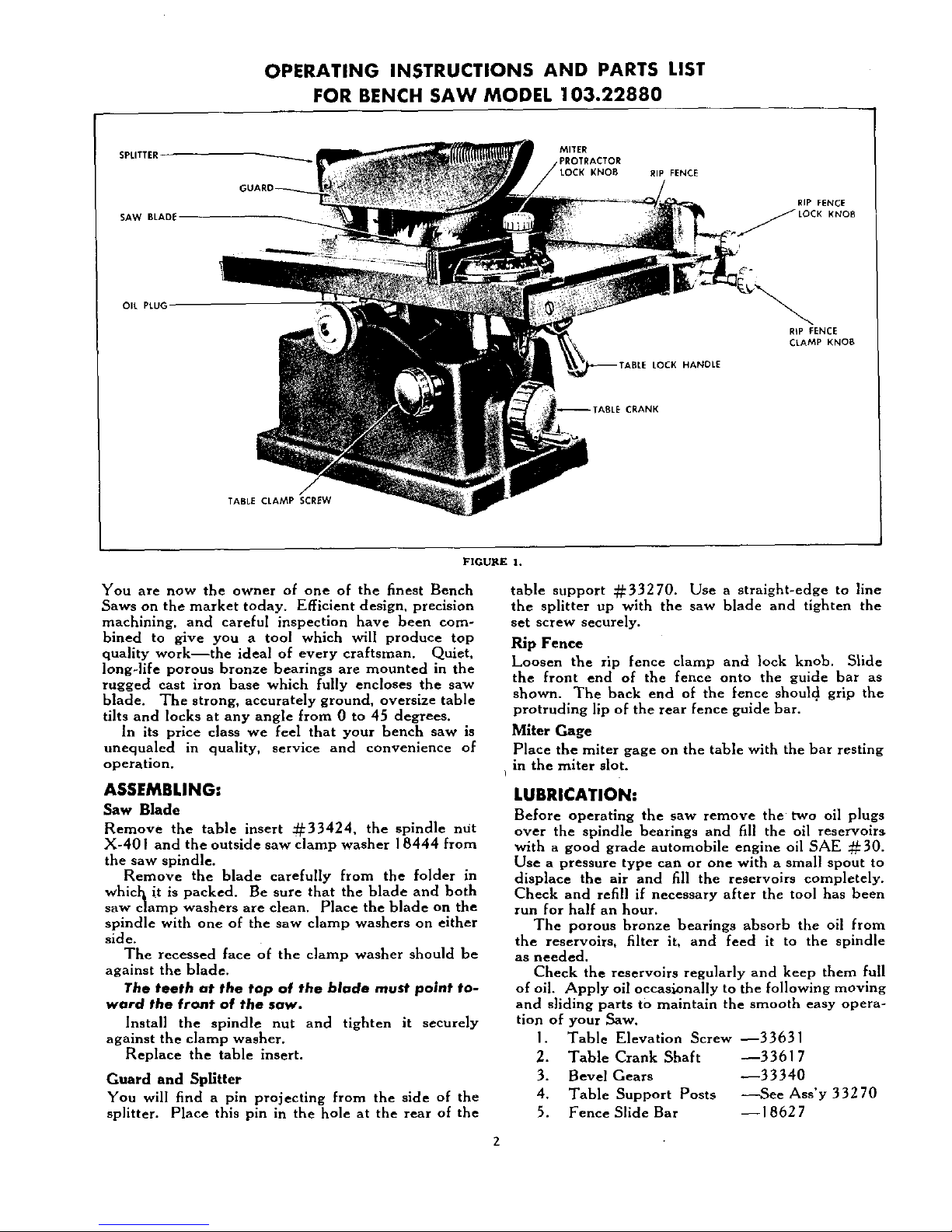
OPERATING INSTRUCTIONS AND PART5 LIST
FOR BENCH 5AW MODEL 103.22880
SPLITTER-
SAW BLADE
MITER
LOCK KNOB
RIP FENCE
RIP FENCE
KNOfi
OIL PLUG
HANDLE
R_P FENCE
CLAMP KNOB
"ABLE CRANK
TABLE CLAMP SCREW
FIGURE 1.
You are now the owner of one of the finest Bench
Saws on the market today. Efficient design, precision
machining, and careful inspection have been com-
bined to give you a tool which will produce top
quality work--the ideal of every craftsman. Quiet,
long-life porous bronze bearings are mounted in the
rugged cast iron base which fully encloses the saw
blade. The strong, accurately ground, oversize table
tilts and locks at any angle from 0 to 45 degrees.
In its price class we feel that your bench saw is
unequaled in quality, service and convenience of
operation.
ASSEMBLING:
Saw Blade
Remove the table insert _33424, the spindle ntit
X-401 and the outside saw clamp washer 18444 from
the saw spindle.
Remove the blade carefully from the folder in
whic_ it is packed. Be sure that the blade and both
saw cramp washers are clean. Place the blade on the
spindle with one of the saw clamp washers on either
side.
The recessed face of the clamp washer should be
against the blade.
The teeth at the top of the blade must point to-
ward the front of the saw.
Install the spindle nut and tighten it securely
against the clamp washer.
Replace the table insert.
Guard and Spfitter
You will find a pin projecting from the side of the
splitter. Place this pin in the hole at the rear of the
table support :#:33270. Use a straight-edge to line
the splitter up with the saw blade and tighten the
set screw securely.
Rip Fence
Loosen the rip fence clamp and lock knob. Slide
the front end of the fence onto the guide bar as
shown. The back end of the fence should grip the
protruding lip of the rear fence guide bar.
Miter Gage
Place the miter gage on the table with the bar resting
in the miter slot.
I
LUBRICATION:
Before operating the saw remove the two oil plugs
over the spindle bearings and fill the oil reservoirs
with a good grade automobile engine oil SAE :_30.
Use a pressure type can or one with a small spout to
displace the air and fill the reservoirs completely.
Cheek and refill if necessary after the tool has been
run for half an hour.
The porous bronze bearings absorb the oil from
the reservoirs, filter it, and feed it to the spindle
as needed.
Check the reservoirs regularly and keep them full
of oil. Apply oil occaslonally to the following moving
and sliding parts to maintain the smooth easy opera-
tion of your Saw.
1. Table Elevation Screw --33631
2. Table Crank Shaft --33617
3. Bevel Gears --33340
4. Table Support Posts -----See Ass'y 33270
5. Fence Slide Bar --18627
Page 3

INSTALLATION:
Three I I/32 inch diameter holes are provided in the
base through which your bench saw should be se-
curely fastened with screws or bolts to a well con-
structed work table or bench.
The saw is designed so that you can mount the
motor below the saw out of the way, the belt travel-
ing through a hole cut in the bench. A large hole
in the bench below the blade will allow sawdust to
drop through. A simple deflection panel may be in-
stalled to keep sawdust off the motor.
Note: If you prefer to install the motor behind the
saw on the bench, it will be necessary to block up the
saw approximately 2 I_ inches above the level of the
motor base to provide clearance for the belt at the
rear edge of the table when the recommended
motor and pulleys are used.
MOTOR:
For general use a I/_ horsepower 1750 R.P.M. motor
will drive the saw with sufficient power.
SPEED:
A 5 inch diameter pulley on the 1750 R.P.M. motor
will drive the saw at the recommended speed--4500
R.P.M.
Caution: If a 3450 R.P.M. motor is used it should
be equipped with a pulley not larger than 2 I_ inches
in diameter.
BELT:
The pulley on your bench saw is intended for use with
a I_ inch wide standard V-belt. When the motor
and saw position is established, measure with a flex-
ible tape around the outside of the pulleys, not in the
V-groove, to determine the length of belt needed.
CONTROLS:
The Table Crank when turned raises or lowers the
table in relation to the saw blade to regulate the depth
of cut.
The Table Clamp Screw when tight locks the table
at the selected elevation. This screw must be loose
when making a change in table height.
The Table Lock Handle is a wrench used to lock
the table in place at any angle from 0 ° to 45% To
tilt the table engage the hex socket of the wrench
on the head of the table lock nut 33422 and turn it
counter-clockwise slowly until the table will tilt with
slight hand pressure on the right hand edge. After
the table is locked in position, the handle may be dis-
engaged from the lock nut and will hang in neutral
position.
The angle of tilt is shown by the pointer on the
calibrated protractor scale just behind the handle.
For your convenience the table leveling screw and
45 ° stop screw have been incorporated to automati-
cally stop the table at 90 ° and 45 ° to the blade.
Caution: Always raise the table at least ¼ inch
from the lowest setting before tilting to 45 ° . The
extra long spindle (for greater dado set capacity)
will hit the table insert from below if the table is not
raised before tilting.
The Rip Fence Clamp Knob when tight clamps
the front of the fence to the fence bar and holds the
fence parallel to the saw blade.
The Rip Fence Lock Knob when tight ,locks the
r_ar of the fence in place by gripping the rear fence
baT.
When changing the position of the fence, loosen
both the lock knob and the clamp knob--slide the
fence to the new position--tighten first the clamp
knob, and then the lock knob.
The Miter Protractor Lock Knob locks the Pro-
tractor at any position from 30 ° to 90 ° in either di-
rection. The angle is shown by the pointer on the
calibrated scale of the protractor.
ADJUSTMENTS:
Every adjustment of your bench saw was carefully
checked and tested before the tool left the factory.
However, due to the exposure of the tool to rough
handling during shipment it might be wise to check
the following points before operation to insure accur-
ate results.
1. The Blade Must Be Parallel With the Miter Slots.
Check as shown in figure 2. Measure from the
same side of the same tooth each time.
2.
LOWEkrAI_E
TO'_LL_PTn
OSCU"
_ISTANCESHO_LD
|EE'_'L
5_[ IOOTH
ATTAK_L[VEL
J
I fENCE_U5 T
.OCKrAmALL_L
Wt_H _ITE_
SLOT
rENC_ AOJUITI_'_ ICl[_
FIGURE 2.
Adjustment may be made by loosening the two
cap screws X205 which hold the table to the tilt
protractor until the table will shift slightly when
tapped with a mallet or block of wood. When
the blade and slots are parallel, tighten the two
cap screws securely.
The Fence Must Lock Parallel With The Miter
Slots. Check by sliding the fence to the edge of
the nearest slot. Tighten the clamp knob against
the front bar. (Do not tighten the lock knob),
The fence should remain perfectly parallel with
the slot.
To adjust loosen the two screws just forward of
the lock knob. See figure 2. With the clamp
knob still tight, pivot the fence until it is parallel
with the miter slot along its full length. Retighten
the two screws.
Page 4

. The Table Leveling Screw should stop the table
at right angles to the blade. See figure 3. Check
with an accurate square. If the table is not square
adjustment of the leveling screw
necessary. Tighten the lock nut securely
after turning the screw.
~45 ° STOP
SCREW
TABLE TILT
PROTRACTOR
FIGURE 3.
4. The 45 ° Stop Screw should stop the table at an
angle of 45 ° to the blade. See figure 3. Check
carefully, if adjustment is necessary, tighten the
lock nut securely after turning the screw. It may
be necessary to reset the pointer to indicate the
proper angle on the tilt scale.
5. The Miter Protractor must be square with the bar
when the pointer shows 90 ° on the protractor
scale. Check with an accurate square and reset
the pointer if necessary.
6. The Table Insert should be flush with the table
surface. To-adjust, loosen the two slotted head
screws (X-532) which you can see from the top
of the insert. You will find four small set screws
(X115) coming up through from the bottom of
the table, two against the front and two against
the rear of the insert. By turning these four
screws slightly, the insert may be leveled and
brought flush with the table surface.
CARE OF THE BLADE:
The blade supplied with this bench saw will give
many hours of efficient cutting service in the average
home workshop without requiring sharpening. When
the teeth become blunted and dull, and a definite de-
crease in cutting efficiency is noted, the blade may be
put hack in good condition again as follows:
1. Raise the table until an oilstone laid on the table
surface will just touch the teeth of the blade. Turn
the blade backwards by hand until the ends of
all the small cutting teeth have been touched and
are the same length.
2. With an 8 inch round edge mill file, file the gullets
(space between the teeth) of all teeth of the same
shape to a uniform depth and width. Maintain
the original shape, bevels, and dimensions. Avoid
sharp corners and nicks in the gullets.
.
The top one-quarter of each cutting tooth should
be set at an angle of approximately 10 degrees.
set should be uniform and should alternate
!lt to right on successive teeth. T_he large
require no set--they should be kept
bapproximately 1/64 inch shorter than the cutting
teeth.
File the bevel of each cutting tooth--I 5 to 20
degrees bevel on the inside front face of each
tooth. Maintain the original bevel angle and be
careful not to shorten the teeth,
Blade Wobble is often noticed at slow speeds
starting or stopping the saw. If this does not
at full speed, check the saw blade and
amp washers for dirt or saw dust on the clamping
'rfaces.
Gummy residue can generally be removed with
'ERATION:
provided with this saw may be used for
both cross-cutting and ripping. However, if continu-
ous ripping or continuous cross cutting is planned,
a rip blade or cross cut blade will operate much more
efficiently.
For proper chip clearance and best general results,
the blade should project through the work-piece
approximately I_ inch.
Saw warped stock with the concave or hollow face
d o'*v'n.
Support long work as it leaves the rear of the table.
Avoid back tracking on a cut.
Do not force material into the blade too fast. Use
a straight, direct, steady feed which does not over-
tax the cutting capacity of the blade.
SAFETY:
While the bench saw is one of the most widely used
woodshop power tools, it is by nature of its general
design, one of the most dangerous in the hands of
inexperienced or careless operators. The bench saw
is not, however, an unsafe tool when used with com-
mon sense and good judgment.
Use a push block rather than letting the hands get
closer than 3 inches to the blade on narrow cuts.
Keep the splitter in place whenever possible. Never
hold the hands over the blade when making blind
groove type cuts. Stand to one side when completing
a cut. A loose piece caught by the blade can fly
back with surprising force.
Always stop the saw when removing waste stock
from near the blade, when making adjustments, or
when changing settings.
Do not wear dangling neck ties, loose baggy
sleeves, etc., while operating power tools.
The guard is supplied with this saw for your safety
--use it to its best advantagel
ACCESSORIES for this saw will be listed in your
catalog or can be obtained from your nearest Sears
Retail Store. An interesting and instructive booklet
entitled "The Circular Saw" is also .available. It
explains many handy special operations which may
be performed on your bench saw.
Page 5

PARTS LIST
PART NO.
18035
18128
18419
18444
1852T
18524
18619
18624
18627
18630
18922
18931
18969
18983
18984
_18992
PART NAME
Pulley with Set Screws .................
Pence Clamp ........................
Fence Guide Spacer ...................
Saw Clamp Washer ...................
Lock Knob Washer ...................
Fence Rod Nipple ....................
Fence Lock Knob ....................
Fence Guide Bar--Rear ...............
Fence Guide Bar--Front ...............
Fence Clamp Knob ...................
Table Tilt Pointer ....................
Oil Hole Plug .......................
Fence End--Rear ....................
Fence End--Front ...................
Fence Equalizer ......................
8 inch diameter--_ inch bore Combination
Blade. Purchase from nearest Sears' Retail
Store or Mail Order house .............
ART NO.
33101
33102
33107
PART NAME
Rip Fence Assemh]y complete ......... '
Miter Gage Assemby complete ..........
Ba_e Assembly--includes 2 Bearings 33813,
and 2 Oil Plugs 18931 ................
33110 Spindle ............................
33170 Spindle Collar and Set Screw ...........
33216 Table
............................. /
33240 Miter Bar ..........................
33250 Table Elevation Lock .................
33270 Table Support .......................
33290 Splitter ............................
333 I 0 Collar and Set Screw ..................
33340 Bevel Gear and Set Screw ..............
33360 Handwheel .........................
33412 Table Tilt Lock Handle ................
33414 Table Tilt Protractor .................
33417 Lock Knob .........................
3342 I Miter Protractor .....................
*Parts marked in this manner may he purchased locally.
33270
X-116 X-110
33414
X-601
X-420
33412
X-1400
33813
X-IO0
X-174_, €
33170
18035
1
33250
IO
3334o
33310
33617
1
X-413
33360
FIGURE 4_BASE AND RELATED PARTS
Page 6

PART NO.
33422
33423
33424
33611
33617
33622
33628
33631
33633
33711
33713
33717
33812
33813
_XIO0
_XI02
*XIIO
_XII5
_XII6
_XI24
_X 155
PART NAME
Table Tilt Lock Nut ................ ,
Saw Guard .........................
Table lnoert ........................
Fence Lock Rod .............. "[ ......
Table Crank Shaft ...................
Retaining Screw .....................
Saw Guard Pivot Pin ..................
Lift Screw ..........................
Table Pivot Pin ......................
Base Partition .......................
Miter Protractor Pointer ...............
Fence .............................
Snap Ring ..........................
Spindle Bearing ......................
Set Screw 1_-20 x I_ Slotted Hd. Cup Point.
Set Screw 1_-20 x _ Square Hd. Cup Point
Set Screw 1_-20 x :34 Square Hd. Cup Pt..
Set Screw 10-24 x 3_ Slotted Hd. Cup Point.
Set Screw _-20 x I Square Hd. Cup Point..
Set Screw 5/16-24 x _ Socket Hd. Cup Pt..
Set Screw 10-24 x 3_ Slotted Hd. Cone Point
*Parts marked in the, .... ,her
PART NO. PART NAME
_XI74 Set Screw 5/I 6-18 x 5/I 6 Socket Hd, Cup Pt,
'sX183 Set Screw 10-24 x I/_ Socket Hd, Cup Point
_X205 Cap Screw 5/16-18 x 3_ Hex Hd .........
X244 Cap Screw I/_-20 x ] Fillister Head .......
_'X304 Machine Bolt _-16 x 2 Square Head ......
_X382 Machine Screw _-20 x 3_ ..............
_X401 Hex Nut--1_-20 .....................
'*X413 Hex Nut--_-16 .....................
_'X420 Hex Nut--1_-20 .....................
'_X429 Hex Nut--10-32 .....................
_X512 Machine Screw 8-32 x _ Round Head ....
_X520 Machine Screw 10-32 x I_ Flat Head .....
X532 Machine Screw 10-24 x 7/16 Fillister Head.
_'X539 Machine Screw 10-24 x _ Round Head ....
X546 Machine Screw _-20 x _ Fillister Head . . .
_X601 Plain Washer 5/16 Std .................
_X605 Lock Washer ¼ Std ...................
a'X606 Plain Washer 3_ Std ...................
_X61 I Lock Washer 5/16 Std .................
_X615 Plain Washer I_ Std ...................
¢XI400 Allen Wrench 5/32 ...................
_'XI803 Sheet Metal Screw No. 12 x _ ..........
may be purchased locally.
FENCE ASS'Y 18969
COMPLETE
33101
18524"_
33290__
33628 X-532/_
33424
33717
MITER GAGE
X-382 ASS'Y COMPLETE
33102
X-615
_18630
33240
X-546
33216
X-420
FIGURE 5--TABL_ AND REBATED PARTS
6 6-49--1700
 Loading...