

Page 1

OPERATING
INSTRUCTIONS
AND PARTS
I,IST FOR
CRAFTSMAN
BEI,T
AND DISC
SANDER
6INCH
Model Number
f
03.?;25jOO
HOW TO
OI?DER
REP.S,IR P^A.RTS
All
parts
listed herein rnay be ordered
through
Sears,
Roebuck
and Co. or Sirnpsons, Sears
Lirnited. When ordering
parts
by rnail
frorn the
rnail
order
house which serves the territory
in
which
you
live,
selling
prices
will
be
furnished on
reguest
or
parts
will be
shipped
at
prevailing
prices
and
you
will
be billed
accordingly.
WHEN
ORDERING
REPAIR PARTS, AITWAYS GM
THE
FOIJ-
IJOWING
INFORMATION AS SHOWN
IN THIS IIIST:
l. The PART
NUMBER.
2.
The PART NAI\[E.
3.
The MODEIJ NUMBER.
4. The NAME of
itern.
SEARS,
ROEBUCK and
CO.-L.S.A.
This
is
the
rnodel nurnber of
your
Sander.
It
will
be
found on a
plate
on
the base.
Always
rnention
this
rnodel
nurnber
when conununicating
with us
regarding
your
Sander or
when
ordering
parts.
This
list is
valuable.
It wiII
to obtain
proper
parts
service.
with
other
valuable
papers.
assure
your
being
able
We
suggest
you
lreep it
SIMPSONS,
SEARS
I,IMITED-CANADA
LITHOGRAPHED
IN
U.
S.
A.
SOURCE
FORM 47919
Page 2
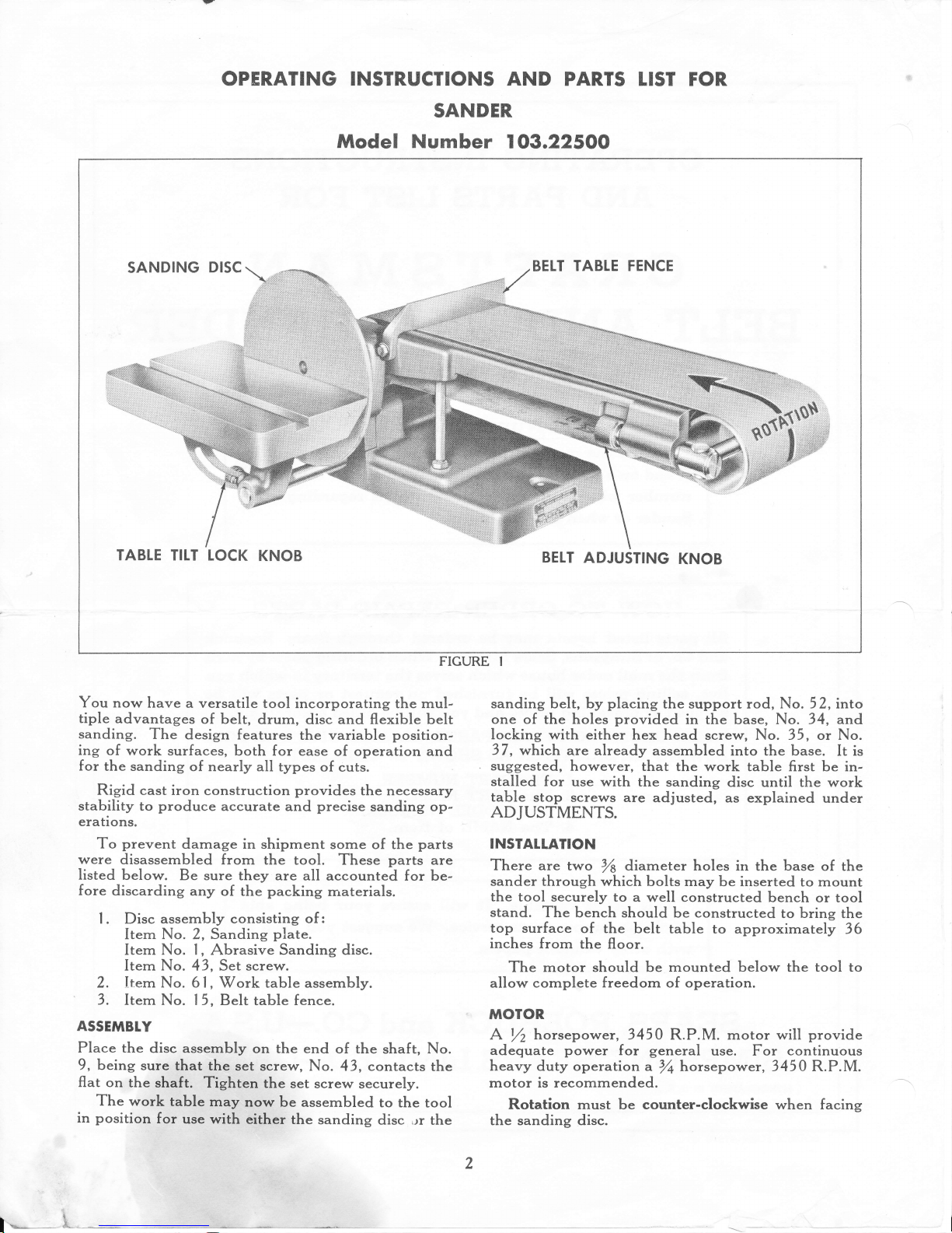
OPERATING INSTRUCTIONS AND
PARTS LIST FOR
SANDER
Model Number
lO3.225OO
SANDING
DISC
FENCE
TABLE
TILT LOCK
KNOB
BELT
ADJUSTING
KNOB
TABTE
FICURE
I
You now
have
a versatile
tool incorporating the mul-
tiple
advantages
of
belt,
drum, disc and fexible belt
sanding.
The
design features
the variable
position-
itg of
work surfaces,
both for
ease
of operation and
for
the sanding
of
nearly all
types
of
cuts.
Rigid
cast iron
construction
provides
the
necess
ary
stability
to
produce
accurate
and
precise
sanding
op-
erations.
To
prevent
damage in
shipment
some of the
parts
were
disassembled
from
the
tool. These
parts
are
listed
below.
Be sure they
are all
accounted for be-
fore
discarding
any
of the
packing
materials.
|
.
Disc
assemblv consisting
of
:
Item No. 2, Sanding
plate.
Item
No. l,
Abrasive
Sanding
disc.
Item
No.
43, Set screw.
2. Item No. 61, Work
table assembly.
3.
Item No.
15, Belt
table fence.
ASSEMBLY
Place the
disc assembly
on the end
of the
shaft,
No.
9
,
being
sure
that the
set
scr€w, No.
43, contacts
the
fat
on
the
shaft.
Tighten
the set
screw
securely.
The
work
table
may
now
be assembled
to the
tool
in
position
for
use with
either
the
sanding
disc
,rr
the
sanding belt, by
placing
the support rod,
No. 52,
into
one
of the holes
provided
in
the
base,
No.
34, and
locking with
either hex head
screw, No. 35,
or
No.
37,
which
are already
assembled
into the base.
It
is
suggested,
however,
that the
work table first
be
in-
stalled for
use with
the
sanding
disc
until
the
work
table
stop screws
are
adjusted, as explained
under
ADJUSTMENTS.
INSTALLATION
There are two
V's
diameter
holes in the base
of the
sander through which
bolts may
be inserted
to mount
the tool
securely to
a
well
constructed
bench
or tool
stand.
The
bench
should be constructed
to
bring
the
top
surface
of the
belt
table
to approximately
36
inches
from
the
floor.
The
motor should
be mounted
below
the tool to
allow
complete
freedom
of operation.
MOTOR
A
Yz
horsepower, 3450
R.P.M. motor
will
provide
adequate
power
f
or
general
use. For
continuous
heavy
duty operation
a
%
horsepower, 3450
R.P.M.
motor is recommended.
Rotation
must
be
counter-clockwise when
facing
the
sanding disc.
*---*
h-
Page 3

3q5o
fzlrnn
lr4oroA.
dl
L"
P,Ju1€V
SPEED
For best
perf
ormance
this tool
should
run at
8p-
proximately
2700
R.P.M. This
speed
is
attained
by
using
a 2 inch
diameter
motor
pulley
with a
Yz
inch
V-groove.
Be
sure
to
specify
the
shaft
diameter
of
your
motor
when
ordering
the
motor
pulley.
BETT
Use a
standard
%
inch V-belt.
To
determine the
belt
length
place
rhotor
and
tool
in operati.g
posi-
tion
and measure
around
the outside
of
the
pulleys
with
a steel tape.
Do
not measure
in
the
grooves.
TUBRICATION
This
sander
is equipped
with
precision
type, sealed
ball
bearings.
These
bearings
were
packed
with
grease
at
the factory
and
require
no additional
lubri-
cation
for
the
life
of
the bearing.
To
maintain
smooth
and
easy
operation
of the
controls,
oil
the
following
parts
occasionally
with any
good
grade
machine
oil:
|
. Belt
adjusting
knobs
Nos.
23 and 33
where
they
enter
the
casting.
2.
Pulley support
pins
Nos.
25 and
29 where
they
enter
the
casting.
coNTROTS
The sanding
belt
may
be
raised from
horizontal to
vertical
position
after
loosenittg
the
two belt table
pivot
lock
bolts,
No.
I 0.
Always tighten
these
bolts
securely before
operation
in any
position.
The belt
adjustir,g knobs
align
the iCler
pulley,
No.
27
,
to
keep the
sanding belt
running
true over.
the
pulleys
and centered
on the
belt table.
These
knobs
also
control
the tension
of
the
sanding
belt.
The table
tilt
lock knob
locks
the
work
table
at any
desired degree
of tilt from 0o
to 45".
The
belt table fence
provides
a backup
for the
work
piece
when
using the
sanding
belt.
T-t(e
RPA
wl
z'i,
faufrl
oil.)
:roaL
2.
Apply
belt tension
by turning
the
two belt ad-
justing
knobs
clockwise.
While
applying
ten-
sion
keep
the idler
pulley
approximately
p?r-
allel
with
the
drive
pulley.
When
proper
ten-
sion
has
been
applied
you
should
be able
to
deflect
the
belt,
as
shown
in
Fig.
2,
ErpproX-
imately
Yz
of
an inch.
Align
the
sanding
belt
so
that
it will
track
on
the
approximate
centers
of the
two
pulleys
and remain
in
one
position
on
the
pulleys,
as
follows:
|
.
Rotate the
belt
bv hand
in
the
correct
direc-
tion,
as
shown
in
Fig.
|
.
2.
If
the belt
tends
to
run
off
to the right,
turn
the
right
hand
knob
clockwise.
If
the
belt
tends
to run
off
to the
left,
turn
the
left
hand
knob
clockwise.
3.
Recheck
the
belt
tension
and
adjust
if
fi€c€s-
sary
by turning
both
knobs
an
equal
amount.
4. The
tool
should
now
be
ready
to
operate.
If,
under
power,
the
belt
does
not track
propetly,
make
very
minor
adjustment
of
the
knobs
while
the
tool
is
in
operation.
When
installirg
new
sanding
belts
follow
the
above
steps.
Be
sure
the arrow
on
the inside
of the
belt
points
in
the
same
direction
as
the
rotation
arrow
shown
in
Fig.
l.
NOTE:
Tighten
all
pulley
set
scre\ rs
after
a
few
hours
of operation.
The
work
table
stop
screws
may
require
adjust-
ment
to
obtain
the
90"
and
45"
settings.
If adjust-
ment
is necessary,
it
may
be
accomplished
as f
ollows:
| . Loosen
the table
tilt lock
knob, No.
5
3, and
using
a combination
square
set the
work table
exactly
square
with
the
sanding
ciisc.
R e-
tighten
knob.
2. Loosen
hex
nut,
No. 50,
and
turn
the square
head
set scr€w,
No.
5
|
,
until it
contacts
tlre
rib
on the
underside
of the
table.
Re-tighten
the
hex
nut,
while
holding
screw
in this
ptsition.
3. Repeat
the above procedure
f or
the 45 "
stop
screw,
No.
59.
CAUTION:
In
placing
the work
table
assemblv
on
the
tool, keep
the
edge
of the
table
as
close
as
pos-
sible to
the
sanding
surface
to eliminate
the
J.rr-
ger
of
thin
work
becomittg
wedged
between
the
table
and
the sanding
surface.
The socket
head
set
screw,
No.
5
5
,
secures
the
table
support, No.
49,
to the
support
rod, No.
52,
and also
serves
as the
lock
stud for
the table
tilt
lock
knob.
If adjustment
of this
stud
is
necessary
loosen
the
tilt
knob and
tighten
securely
with
the
Allen
wrench
provided.
The
sanding
belt
table
when
used in
the vertical
position
should be
set square
with
the work
table,
as
follows:
l. After
the
work
table
has been
installed for use
with the
belt,
loosen
the
two belt
table
pivot
Iock
bolts,
No.
| 0.
2.
Place a combination
square
on the
work table
and
pivot
the belt
table until
the two tables
are
90" to each
other.
3.
Re-tighten
pivot
lock bolts.
This
procedure
must
be repeated
each
time
the
position
of the
belt table
has been
changed.
*
"i:;.*
;:'
il"?T:
;:T ?:,'ff"
n :::",|;ni
ff^r:
FIGURE 2
ADJUSTMENTS
Tension
the
sanding belt
before operatirg,
as
fol-
lows:
l. Face the end of the tool with rotation arrow,
see Fig. l,
pointing
away
from
you.
Page 4

ing
operations.
For
extreme
accuracy
the
pro-
tractor
head
should
be
set
in
relation
to
the
sand-
ilg
disc
or belt
table
each
time
a
new
position
is
desired.
OPERATION
The sanding
belt
and
sanding
disc
furnished
with
this
tool are
for
general
use.
They
are
suitable
for
use
on
materials
such
as
metal,
wood,
or
plastics.
Since
a non-hardening
type
of
disc cement-[.as
been
used
to fasten
the
abrasive
paper
to
the spnding
plate,
the
abrasive
disc may
be
quickly
replaced
with
one of
a different
grit.
Drum
sanding
may
be
done
at either
end of
the
sanding
belt
table.
See
Fig.
4 for
a typical
applica-
tion.
Flexible
belt sanding
may
be
done
on the
back
of
the
belt
with
the
belt
table
in
vertical
position,
&s
shown
in
Fig.
5.
Release
the
belt
tension
to
suit the
curve
of
the
work
piece.
Quality
of finish
d.pends
entirely
upon the
abra-
sive
grit
and
the
handling
of the
work.
Highest
qual-
ity
is
obtained
by
first
rough
sanding
with
the coarser
gri_ts,
then
changing
to
finer
grits
and
making
several
light
passes.
Abrasives
are
available
in
three
grits-fine,
rrr€-
dium
and
coarse.
The
belt
and
disc furnished
are
both
medium
grit.
FIGURE
5
SAFETY
Due
to
the functions
of
this
tool
the
revolving
parts
must
remain
exposed.
Be
careful
!
Hold
the
work
firmly
so
that
it
may
not
be
driven
from
your
hands
allowing
them
to
come
in
contact
with
the
abrasive
surfaces.
Use
the
belt
fence
whenever
possible.
Be
sure
the
rotation
is
correct.
Do not
wear
clothes
which
are
loose
or
dangling.
Be
sure
all necessary
adjustments
have
been
made
before
operati.g
tool.
In
installations
requiri.g
a
belt
guard
see
Fig.
6
for further
information.
FIGURE
3
Surface sanding
is
best
accomplished
by
holding
the
work piece
firmly,
but
not
ipplying
too *.r.f,
pressure
to
the
sanding
surface.
The
work
piece
should
be
moved
back
and forth
over
the
sanding
belt
to
maintain
even
belt
\
rear
and
eliminate
groovirg.
Wood
should
be
sanded
with
the
grain.
Use
the
belt
table
fence,
see
Fig.
l,
to
back
rp
the
'work:
If the
work
piece
is
lorg"i
than
the
b.li
sur-
.,fice, remove
the f.rr..
to
allowJull
use of
the
belt.
Exra long
work
should
be supported
as
shown
in
Fig. 3, to
eliminate
sag.
Disc
sanding
has
rough
ends
of
wood.
FIGURE
4
its
greatest
usage
in truing
the
Page 5

^
^
"*
e'UaAlS
*.o(\?3
hu
h/.*tr'
cn
il
44--.*4&
EXPLODED
VIEW_MAIN
ASSEMBLY
59\
53
/
WORK
TABTE
ASS'Y
COMPLETE
6l
EXPLODED
VIEW-WORK
TABLE
ASS'Y
Page 6

Item
Order
by
No.
Part
No.
PART
NAME
|
38834
9
In.
dia.
sand
PaPer
disc.
Purchase
from
your nearest
Sears
retail
store
<lr
mail order
house.
Ask
for
Cata'
log
No. 9-2526.
State
grit
wanted
. b
a
'
2
38
180
S"itait
g
pl.tt with
set
screw
^
i/'
3
17
|
7
0
-
Iq-olp..qtley
.qith
".g!
".try
,*ic##**'"@
'rt
{
n
4'.-ffi:
"ft
lo{.tl
rtetarnlng.__T]Bg----
-r-*-zzgrr-
-R;Htrfi
;;fi;--
7
47
616 Belt
table
bushing
8 38833
'Retaining
lins
i
-9*
-
47 61 7_
*_D_nys***-haJt-*:-*-
av
(}
f
ft
t'e f?
(
/'\
l*0-**-*X:ZSl
*"Ca;""'"*
5/16-l I x
l/2hex. hd.
| | X-623
Plain
washer
2l
/64
I.D.
x
t/s
O.D.
l2
|$,IIl
-Refeiprn-s*-Iu1g
*
*Tt**W;;;*
5
Ito-l
I x I hex. head
l4
X-601
Plainwasherll/32
I.D.xll/16
o.D.
Belt table fence
Belt
table support
post
Drive
pulley with set screw
Set
screw
Y4-20
x
5
/
16 socket
head
with
cup
point
Set
screw
5
/16-
l8 x
/2
socket
head
with
cone
point
Belt
table
Ball
bearing
Retaining
ring
Belt
adjusting knob
Swivel
Pulley
support
pin
Set
screw
Y4-20
x
5/16 socket
head
with
cone
point
Idler
pulley
with
set
screw
Idler
bearing
Pulley support
pin
Retaining
swivel
Set
screw 5/16-18 x 5/16 socket
head self
loclcing
with
flat
point
Set
screw
5
/
| 6-1 8 x
/2
socket
head
self
locking
with
dog
point
PARTS
LIST
Item
Order
by
No.
Part
No.
PART
NAME
33
47
618
Belt
adjusting
knob
3 4
47 120
Base
3 5
sX-205
C"p
screw
5
/
16-
1
8 x
/4
hex'
head
36
X-456
Hexj.*nut7/16-14
37
X-236
C.p
""t"*
5/l6'
I I x
2%
hex.
head
3 8
47 2
12
Table
suPport
bracket
39
*X-6
l l
Lock
washer
5
/
16 inch
40
X-33S
Machine
screw
5/16-18
x lsAPhil-
4n
4t
---r-o'-u
jA::nd
head
'-
-42-----K-n9
Sei
screw
5/16-18
x
5/16
socket
head
with
cup
point
43
X-179
Setscrew5/16-18
x5/16
socket
head with
cup
point
44
387
37 Wrench
45
*X-
|
403
Allen
wrench
5
/32
46
47 8l3
Sanding
belt
6 x
48
inches.
Pur-
chase
from
your
nearest Sears
retail
8:;TJ
T,:l
";1ii
l,l
"""r,#o
-?l
4t
3ssi5
HiTil;
w 5/l
6- | 8 *
T+slotted
head
self
locking
with
cone
point
48
38225
Work
table
49
38226
Work
table
support
50
'eX-420
Hex
nut
%-20
5l
*X-
|
l6 Set screw
V4-20
x
I
square
head
52
38653
Work
table
support
rod
53
38654
Work
table
tilt
lock
knob
54
X'60
1
Plainwasherll/32
l.D.xll/16
o.D.
55
X-3606
Set
screw
5/16'18
x
l%
socket
head with
half dog
point
56
X-741
Machinescrew5/16-18
xYz
hex.
hd. with
external
tooth
lock
washer
Work
table
lock
arm
Set screw
5/
| 6- | 8 *
3A
slotted
head
self
locking
with cone
point
Set
screw
Y4-20
x I square
head
Hex
nut
V4-20
Work
table
assembly
complete
| 5
38224
f6 47615
l7
47 190
18 x-t73
t9
x-|70
20
47211
2l
38832
22
38833
23
47 618
24
47
613
25
47 6t
4
26 X-172
27
47180
28
47611
29
476t4
30
47 6t2
3
|
X-3
605
32
4781
|
57
38738
58
38835
59
*X-
l l6
60
tx-420
6 |
38102
*Standard
hardware items_may
be
purchased
locally.
This sheet
is
intended
for
instruction and repair
parts
only
and
is not
a
packing
slip.
The
parts
shown and listed may include accessories
not
necessarily
part
of this tool.
ACCESSORIES
Fig.
6
illustrates
accessories
for
your
sander.
Tool Stand-Qalalog
No. 99-2204
Guard-Q31alog
No. 9
-225
|
Powr
Panl-Catalog
No.
9-2120
6
 Loading...