

Page 1
This list is valuable. It will assure your being able to
obtain proper parts service at all times. We suggest you
keep it with other v_uable papers.
ROEBUCK and CO.
Form 150
Page 2
J
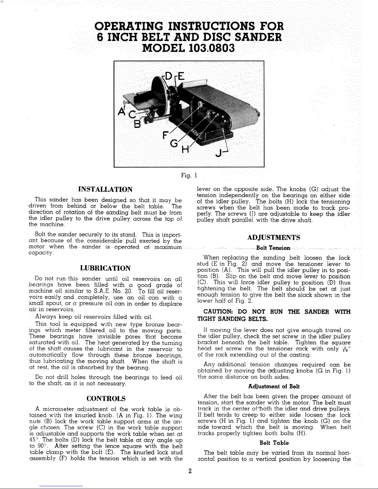
Fig. 1
This sander has been designed so that it may be
driven from behind or below the belt table, The
direction of rotation of the sanding belt must be from
the idler pulley to the drive pulley across the top of
the machine.
Bolt the sander securely to its stand. This is import-
ant because of the considerable pull exerted by the
motor when the sander is operated at maximum
capacity.
Do not run this sander until oil reservoirs on all
bearings have been filled with a good grade of
machine oil similar to S.A.E No. 20. To fill oil reser-
voirs easily and completely, use an oil can with a
small spout, or a pressure oil can in order to displace
air in reservoirs.
Always keep oil reservoirs filled with oil.
This tool is equipped with new type bronze bear-
ings which meter filtered oil to the moving parts.
These bearings have invisible pores that become
saturated with oil. The heat generated by the turning
oI the shaft causes the lubricant in the reservoir to
automatically flow through these bronze bearings,
thus lubricating the moving shaft. When the shaft is
at rest, the oil is absorbed by the bearing.
Do not drill holes through the bearings to feed oil
to the shaft, as it is not necessary.
CONTROLS
A micrometer adjustment of the work table is ob-
tained with the knurled knob. (A in Fig. 1). The wing
nuts (B) lock the work table support arms at the an-
gle chosen. The screw (C) in the work table support
is adjustable and supports the work table when set at
45 °. The bolts (D) lock the belt table at any angle up
to 90°. After setting the fence square -with the belt
table clamp with the bolt (E) The knurled lock stud
assembly (F) holds the tension which is set with the
lever on the opposite side. The knobs (G) adjust the
tension independently on [he bearings on either side
of the idler pulley. The bolts (H) lock the tensioning
screws when the belt has been made to track pro-
perly. The screws (J) are adjustable to keep the idler
pulley shaft parallel with the drive shaft.
ADJUSTMENTS
Belt Tension
When replacing the sanding belt loosen the lock
stud (E in Fig. 2) and move the tensioner lever to
position (A). This will pull the idler pulley in to posi-
tion (B). Slip on the belt and move lever to position
(C). This will force idler pulley to position (D) thus
tightening the belt. The belt should be set at just
enough tension to give the belt the slack shown in the
lower half of Fig. 2.
CAUTION: DO NOT RUN THE SANDER WITH
TIGHT SANDING BELTS.
If moving the lever does not give enough travel on
the idler pulley, check the set screw in the idler pulley
bracket beneath the belt table. Tighten the square
head set screw on the tenmoner rack with only _,"
of the rack extending out of the casting.
Any additional tension changes required can be
obtained by moving the adjusting knobs (G in Fig. 1)
the same distance on both sides.
Adjustment of Belt
After the belt has been given the proper amount of
tension, start the sander with the motor. The belt must
track in the center of-both the idler and drive pulleys_
If belt tends to creep to either side loosen the lock
screws (H in Fig. 1) and tighten the knob (G) on the
side toward which the belt is moving. When belt
tracks properly tighten Both bolts (H).
Belt Table
The belt table may be varied from its normal hori-
zontal position to a vertical position by loosening the
Page 3

E-/
B
i
screws (D in Fig. 1). Both screws must be tightened
with a wrench when the desired angle is reached.
Work Table
The adjustable work table can be placed in two
positions on the machinein front of sanding disc or
in front of the sanding belt when sanding belt is in a
vertical position. It can also be used in the latter loca-
tion as a rest when the sander is operated horizontal-
ly.
To ad}ust the table to make a right angle with the
disc hold a try square with one leg against the disc
and one leg on the table. Screw the knob (A in Fig.
1) in or out until the square rests evenly against both
surfaces. Bring the inside nut on the stud against
the table and then tighten the second nut securely
against the inner nut.
To adjust the table at the lower stop unscrew the
knob until the table rests on the work table support.
Using a bevel set at 45 ° with one side against the
disc and the other on the table, turn the square head
set screw in the yoke support in or out until the two
sides of the bevel rest on both surfaces. Then tighten
the locking nut.
Fig. 2
OPERATION
The idler pulley on this sander is rubber covered
and can be used for drum sanding as shown in Fig.
3, Long pieces may be finished on this sander by re-
moving the fence and, if necessary, the disc.
The sanding of metals or plastics require aluminum
oxide belts. The belt supplied on the tool is for use
on wood.
It is preferable to sand with the grain. Cross grain
sanding will show sanding marks. To produce a fine
finish it is advisable to oscillate the material across
the belt slowly. In this way marks in either direction,
lengthwise or across, the grain, are reduced to a
mimmum.
The lower side of the belt may be used as a flexi-
ble belt sander, particularly with the table in a verti-
cal position. For butt sanding on the belt use the
fence as a stop. Both straight and compound angles
Protractor
The adjustable pointer may be reset at any time
that the protractor becomes out of adjustment To
correct the reading loosen the knurled knob, hold
head and bar against a try square and retighten the
knob. Then reset the pointer to the 90° mark.
SPEED
The correct operating range for this sander is from
1200 to 1600 RP.M. Use 2" diameter hubless pul-
!eys to obtain this speed with a 1750 R.P.M motor.
A 1750 R,P.M, 1/3 H.P, motor is recommended for
ordinary work, A 1/2H.P. motor is recommended for
heavy duty on production operations,
Fig. 3
may be sanded with the aid of the protractor and the
angle adjustment of the work table.
To replace the abrasive on the disc remove the
complete disc and soak in hot water. The paper can
then be peeled off. Be sure metal disc is dry before
cementing the new abrasive,
While a guard for the "V" belt is not supphed, due
to the variety of possible installations, it is strongly
recommended that suitable protection be provided by
the operator.
Page 4

HOW TO ORDER PARTS FOR MODEl- NUMBER 103.0803 BELT AND DISC SANDER
All parts listed here may be ordered through any Sears retail or mail order store. Parts are shipped
prepaid. When ordering repair parts, always give the following information.
L The Part Number in this list.
2, The Part Name and Price ill this list,
3. The Model Number which is 103.13803 and will be found ou a plate on the right side of the base.
 Loading...