

Page 1
FOR CDI_RE[{_ SELLING PEICE_
ORDERING L_0PJ_iATI N.
i
SEARS, ROEBUCK an
FOBM I08-2
Page 2

t
i
- -2 -
Page 3
Part
Number Name of Part
486-18 Protractor Clamp Pin Spring
486-25 Shaft Collar Assembly
592-36 Wrench
6864 _'ig Saw Blade .Replaced by X-1125
68:)9 Motor Support' Clip .....
10511 Protractor Lock Wrench
12321 Protractor Clamp Nut
12455 Chuck Housing--Lower ......................
12456 Blade Centering Cover
12457 Socket Head Clamp Screw
12460 Chuck Assembly--Lower
12462 Slotted Head Set Screw
12464 Threaded. Plug
12504 Table Insert
12512 Chuck Jaw Housing Lock Nut
12513 Chuck Jaw Stationary
Upper ..... Replaced by 15172
Lower Replaced by 12460 plus 12464
12514 Chuck Jaw Movable
Upper .... Replaced by 15172
Lower .................. Replaced by 12A60 plus 12464
_251_uck Jaw Pilot
/
Upper _Replaced by 15172 V"
Lower ........................... Replaced by 12460 plus 12464
12554 Machine File Jaw Screw ..... Replaced by 12460 plus 12464
12555 Chuck Jaw Clamp Screw
Upper .............................. Replaced by 15172
Lower Replaced by 13460 plus 12464
12556. J'aw Clamp Screw Pin . _;
Upper ....................................... Replaced by 15172
Lower ....................... Replaced by 12460 plus 12464
13030 Protractor ........................................ Replaced by 130_0
13035 Table Protractor Guide Screw, Short
13037 Protractor Guide--Front ........... Replaced by 15113
Rear ............. Replaced by 151_8
13038 Table Protractor Clamp Replaced by 14021
13039 Table Stop Link __.Not Used !
13041 Protractor Scale "-
13050 Protractor Assembly ...........................................
14021 Table Protractor Clamp "
14048 Mitre Gage Pointer
14059 "Table Protractor Lock Screw .... Replaced by X-316 []
14069 Protractor Clamp Pin--Rear" I
14082 Mitre Gage Plunger Assembly '_!
15001 Base ................................................................. [
15002 Arm ....................................................
15003 Table II
15006 Table Support ................................. Replaced by 15173 !i
151;07 Boot Retainer ........................ _ ........................... i
15008 Lower Guide Rod Bracket ........................
15009 Yoke ................................................................
15011 Yoke Pin ................................................. ._ ................ I
15013 Lower Guide Rod ............. Replaced by 15107 _i
15015 Pulley Shaft ............................... Replaced by 15145 ,,
15017 Crank Case Cover ...............................
15018 Mounting Insulator ...............................................
i_._-_ Pump Tube ........................................Replaced by 15085 i,
15023 Pbtmp Tube Cap ...............................................
15024 PumI¢ Leather ...................................................
15025 Pump S'_ring ..................................
15026 Lower Gtfide Rod Spring .._'-_.',.----'._.'_.Z,.'_..._ .............. Not Useo
15030 Upper Go(de Tube Assembly ...........................................
15031 Pump Tube Support ............................... i
15032 Pump Tube Sopport Pilot ...............................
15033 Pump Tube Support Pilot Lock Screw .......
15034Saw Guide Rod ............................... I
15035 Thrust Roller Holder Guide )
15036 Saw Thrust Roller ..............................
15037 Thrust Roller Holder
15038 Hold Down Spring ............................
15043 Thrust Roller Pin
15044 Crank Case Gasket
15049 Boot Spring ................................ 7,....... .L__
15050 Protractor Lock Plunger Housing _crew
15051 Boot
15053 Motor Pulley .....................................
15054 Jig Saw Pulley .........................................
15055 Thrust Roller Holder Support .....................
15056 Motor Support
15057v Belt _,,_32",'---?.s'Z?..Z__ZT.-Z.'_..-Z-:._'_i,'ia_'%-_,_l_55
15059 Pump Spring Guide ._.
15062 .law Clamp Screw Pin--Upper ............... Replaced by 15172 ii
--Lower Replaced by 12460 pins 12464 r
15066 P_Imp Leather Washer'
15072 Motor Adjustment Bracket .............................
15074 Motor Adj. Bracket Thumb Screw ...... Replaced by 15114
15075 Saw Guide Rod Lock Knob Assembly .....................
15076 Crank Case Assembly Includes 15004 (1) X-8!4 (1)
Crank Assembly .- ...... Replaced by 15145
Sleeve ......................................
Assembly ....... Replaced by 15172 j/
.law Assembly ................ Replaced by 15172
Assembly Replaced by 12460 plus 12464
includes 15022. (I) 15070 (!)
15073 (1) ---_ ..........................................
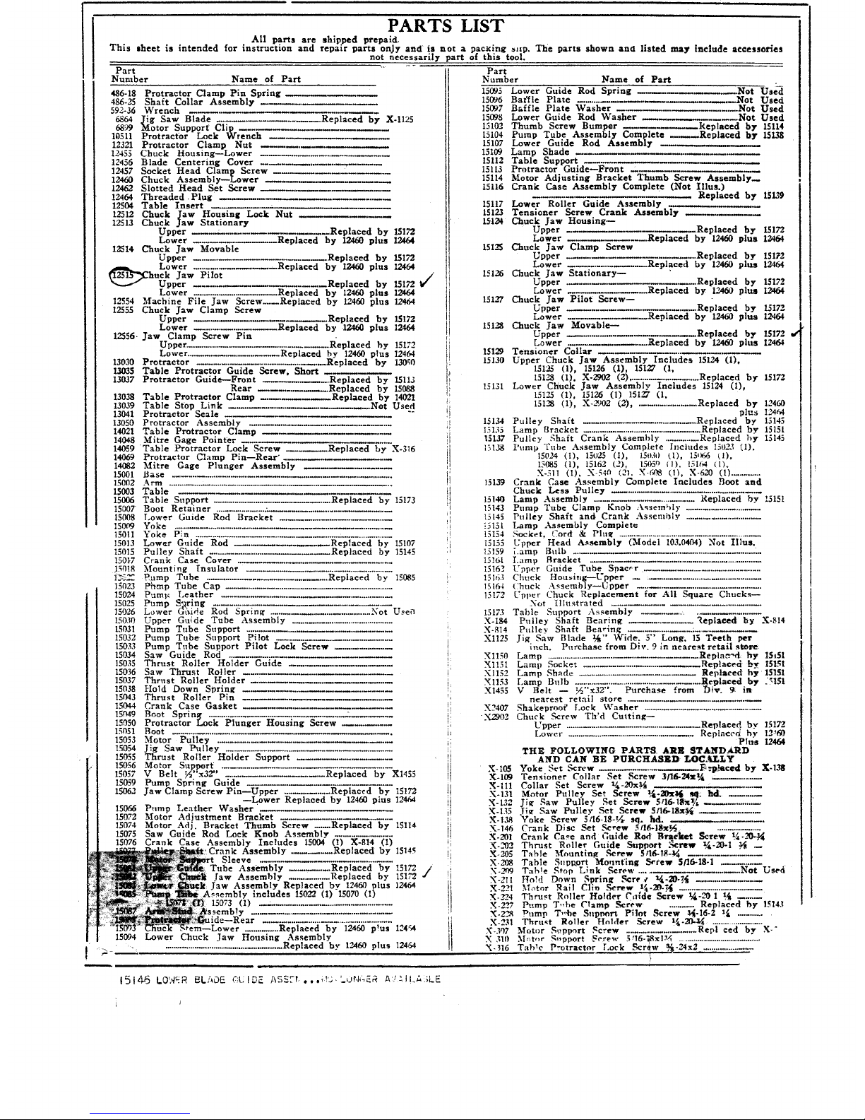
PARTS LIST
All parts are shipped prepaid,
This sheet is intended for instruction and repair parts onJy and is not a pac_ting _np. The parts shown and listed may include accessories
not necessarily part of this tool.
.............. Replaced by 12460 p_us 12454
15094 Lower Chuck Jaw Housing Assembly
• ...................................................... Replaced hy 19.2460 plus 12464
,,i
15 I.d..6 LO'>/_ R BLADE _;l.; I DE ASS?!.,. ,it'.;. '_,_)t,I,_?_.R A'!-' ! I.A _LE
Part
Number Name of Part
15095 Lower Guide Rod Spring
15096 Baffle Plate
15097
15098
15102-
15104
15107
15109
15112
15113
15114
15116
X2407
X2902
X-105
X-109
X-Ill
X-131
X -132
X-135
X.t38
X- 146
X-201
X-202
X-_5
X.L_8
X.2nw
X-211
X.221
X- 2"24
X-2_
X-22_
X-231
_-307
X ,31(I
X-H6
-_.Not Use-d
..... Not Used
Baffle Plate Washer Not Used
Lower Guide Rod Washer ........ Not Used
Thumb Screw Bumper .Replaced by 15114
Pump Tube Assembly Complete Replaced by 15138
Lower Guide Rod Assembly
Lamp Shade
Table Support ........
Protractor Guide--Front
Motor Adjusting Bracket Thumb Screw Assembly_
Crank Case Assembly Complete (Not Illus.)
Replaced by 15139
15117 Lower Roller Guide Assembly
15123 Tensioner Screw Crank Assembly
15134 Chuck Jaw Housing--
Upper _Replaced by 15172
Lower Replaced by 12460 plus 12464
151"_ Chuck Jaw Clamp Screw
Upper ...... Replaced by 15172
Lower Replaced by 12460 plus 12464
15126 Chuck Jaw Stationary--
Upper .... Replaced by 15132
Lower ............... Replaced by 12460 plus 12464
15127 Chuck Jaw Pilot Screw--
Upper .Replaced by 15172
Lower Replaced by 12460 plus 12464
15128 Chuck Jaw Movable--
Upper _Replaced by 15172.
Lower ............... Replaced by 12460 plus 12464
15129 Tensioner Collar
15130 Upper Chuck `law Assembly Includes 15124 (1),
151_ (I), 15126 (I), 15127 (I.
15128 (I), X-2902 (2) ........................ Replaced by 15172
15131 Lower Chuck Jaw Assembly Includes 15124 (I),
15125 (1), 15126 (1) 15127 (1,
15128 (1), X-_)02 (2) .................... Replaced by 12460
plus 124_4
15134 Pulley Shaft .......................................... Replaced by 13145
13135 Lamp Ilracket ................................................ Replaced by 15151
15137 Pulley _haft Crank Assembly .............. Replaced by 15145
15138 Pump Tube Assembly Contptete Includes 15023 (I),
15024 (1), 15025 (1), 15030 1l), 19k66 (1),
15085 (1), 15162 (2), 15050 IlL 151€k4 IIL
X-311 (I), X-540 (21, X-(_ (1), X-620 (1) ............
15139 Crank Case Assembly Complete Includes Boot and
Chuck Less Pulley ..........................................
15140 Lamp Assembly ................................... Replaced by 15151
15143 Pump Tube Clamp Knob Assembly ............................
15145 Pulley Shaft and Crank Assembly .............................
"_,5151 Lamp Assembly Complete
15154 Socket, Cord & Plu_ ...........................................................
I5155 Upper Head Assembly (Model 10,L0404) Not Illus.
15159 ;.amp Bulb
I5!61 Lamp Bracket ....................................................
15162 Upper Guide Tube Spae_'r- .....................................
15163 Chuck Housi,g--Uppor .........................................
15164 Chuck Assembly--Upper ............................................
15172 Upper Chuck Replacement for All Square Chucks--
Not Hlustrated .................................
15173 Table Support Assembly ..........................
X-184 Pulley Shaft Bearing ................ Replaoed by X.814
X-814 Pulley Shaft Bearing .................... :...........
X1125 Jig Saw Blade _" Wide. 5" Long, 15 Teeth per
incb. Purcbase from Die. 9 in nearest retail store
XlI50 Lamp ...........................................Repla_'d by 15t51
XI151 Lamp Socket ................................ Replaoed by 15151
X1152 Lamp Shade ............................... Replaced by 15151
X1153 Lamp Bulb .................................................... Replaced by _3151
X1455 V Belt -- ½"x32". Purchase from Die. 9. in
nearest retail store ...........................................
Shakeprooi' Lock Washer ................................
Chuck Screw Th'd Cutting--
Upper ............................................ Replaced bY 15172
Lower ............................................ Replaced by 12_60
Plus 12464
THE FOLLOWING PARTS. ARE STANDARD
AND CAN BE PURCHASED LOC,_I_Y
Yoke Set Scrcw ./_.'p_ecd by X-138
Tensioner Collar Set Screw 3/16-24xSA
Collar Set Screw _/_-20x_
Motor Pulley Set Screw a&-20x!4 _ hd_ .....
Jig Saw Pulley Set Screw 5tl6-1$X_i
.li_ Saw Pulley Set Screw 5t16-1_x_ .................
Voke Screw 5t16-18-t4 sq. hd.
Crank Disc Set Screw 5116-18x_j
Crank Ca_e and Guide Rod BraCket _creg"_)_:'-_
Thrust Roller Guide ._pport :qcrew _x/_-20-1 _ __
Table Mounting Screw 5rl&!8-_ ................
Table Supgort Mo,tnt'ing Screw $/16-18-1 ...........
Tab!e Stop Link Screw .................... Not Used
Ho!d Down Sprinlt .%err € 141-21}-_t ....................
.Motor Rail Clln Serew t_-20.M ..........................
Thrust Roller Holder Ca{de Screw t_t-20 1 1/_ .....
Pl:mp T-be Clamp Screw ......... Replaced by 15143
Pomp T,,_e Sttpl_rt Pilot Screw _-16-2 t_ ..........
Thrust Roller Holder Screw 1,_-20-_4 ......................
Motor Svpport Screw ........................ Repl ced by X-"
.M_t¢_r ,q-pport Screw 5q6-_Sxl_6 ....................................
Table Protractor Lock Scr_w,,S_-24x2 .........................
Page 4

X-I17 "Motor Support Screw Nut 5:1o--;.g ..............................
X 420 Roller lttJ.'dcr _;ul,le Screw N;_t _.-_1_ ........................
X_4.'I Motor Rail Clip Screw Nut 1-/,-20 Sq. l,id .................
X-432 Protractor (;i.Iide ._z,_trew Nut _-24 ...................................
X-4.t3 Protractor Scale Screw Nut No. 4-40 ..............................
X-436, Lamp Bracket Screw Nut No. 5-40 ........ R,_'ae'_-d by"
X-51t Pump Leather Retaining Screw No. t0-24x_ ...........
X-512 ProtraO:'r Pointer Screw No. 8-32x_ .............................
XL523 Shadt, Soppm't Screw No. 5-40x5_16.. ..................................
X-524 Protractor Scale Screw No. 4-40x_il ..............................
X-540 Guide Tube Spacer _:rew No. 6-32x3/1_ ........................
X-(_H Motor 3,lotmting Screw Washer 5116 Std ................
X-605 :Hold Down Spring Lk. Washer % Std .................. ;'-.
X-_Xi Boot Shield Washer _,_ Std .............................................
X-@_7 Crank Case Washer V4 Std. ........................................
X-608 Leather Retainer Sc. Lk. Washer all6 Std ...........
15131
,i
t
X-c,_:_ ._:l_p Bracket Screw Wash.'' 3116 Std .......................
X-611 Tah'.t Mounting Screw Lk .... a_her 5/10 Std ..........
X-M5 l.anlp ihacket Spacing Wa*i,er 1_ Std ..................
X-61G ProT_ Guide Screw Lk. \_asher -_ Std ..................
X-61_ Pump Tube Clamp Screw Washer 5.,16 Std ..............
X-ol8 Protractor Scale Lk. Washer No. 4 Std ......... Not r!sed
X 619 Plunger Housit'.g Lk. Washer No. 5 Std ...................
X620 Pure> Leather _'rew Washer 13164-1 .........................
X1019 Lamp Bracket _Itg. Screw 3/16--24x}_ ...... ._ .............
Xii03 Clamp Piu Cotter Pin 1116 Std ...........................
XI_0 Lamp Braeket Mtg. Se. Nut 3/I6--24 ..................
X1304 Lower Grade Rod Cheek Ball 9!32 .............................
X.!400 Ailen Wrench 5/32 Across Flats ....................
X-2501 Filier Pipe UL Pipe Coupling ...................
X-2a01 Filler gbow ,_ Std Elbow ..................
X-2701 Plug l_t Pipe Plug (Male) ................................
THE FOLLOWING PARTS ARE SOLD SEPARATELY AS ACCESSORIES
RIP FENCE AND TABLE EXTENSIONS
227.8 I1 12320 Lock Rod Nipple ......................................... Replaced by 12330
I
12330 Lock Rod Nipple ...................................................
! 15029 Ftnee Guide--Front .........................................
I 15021 Fence Guide-Rear .......................................
15046 "Fable Extension--Front ..............................
i{ X-l15 Aligning Screw ............................................
:I X-209 Equalizer Clamp Screw .............................
!i X-428 Lock Rod Nut, Fence Guide Nut
[ X-605 Fence Gnide Screw Lock W_tsher,
Equalizer Screw Lock Washer
ii X-517 Fence Screw
_ X-MS Equalizer Screw Plain Washer
!i X-I101 Cotter Pin ................. :............................. Not Used
15t_h) Complete Unit ....................... See Sears Catalog No,
12&;4 Fence Guide Spacer .............................................
12255 Fence Guide _erew--Long ...............................................
12256 Fence Guide Screw--Short ...........................................
I22t£1 Fence Sub-Assembly--Long ..................................
12263 Fenee End--Front ...............................................
12200 Rip Fence Equalizer ................................................
12_a Rip Fence Clamp Lever ....................................
!2272 Table Extension--Long ...........................................
t2__Jl Fence Assembly Complete .............................. ;.........
12315 t;euce End_Rear ..........................................................
12317 Rip Fence Lock Rod_Long ..............................
IZH8 Rip Fence Clamp--Rear ...............................................
12319 Rip Fence Clam9 llolt .........................................................
LOWER ROLLER GUIDE ASSEMBLY--COMPLETE
F'rat Complete l_'nit ....................................................................... Not Used , X420 Holder Screw Nut ..............................................
15t!7 Lower Rolh-r Guide Assembly Inelt!des 15036 (11, i X-o01 Hinder Support Screw Washer ...... Supplied with tool
15037 I1), 15043 (1). X-202 (1), X-_27 (11 1 X-oil5 Holder Screw Lock \Vasher ............... Supplied with tool
X-420 II) ......................................................................... - X-607 Holder Screw Washer ....................................
15036 Saw Thrust Roller ............................................................. It X-61l Holder Support Screw Lock..,Washer Supplied with tool
]5!}37 Thrust Roller Holder .................................................... '!I X-208 Support Screw .............................. S'pplied with tool
13t_43 Thru_;t Roller Piu ................................................................ i X-224 ttolder Screw ........................................... Replaced by X-202
X-2{12 IIohler Screw ..............................................................................
¥ILING lAWS
iSt_-Coml_te-Unit ............................. Rep!aced by 12460 plus 12464 it 12560 Jaw Clamp Screw .................. Replaced by !2460 plus 12-,64
_2=45 Movable Jaw ................................ Replaced.by 1240) plus 12464 i! 15080 Filing Jaw Housing ............. Replaced by 12460 plus 12_0
1!:,46 ._Stati}_.n.a_ry Jaw.,_. ......................... Replaced by 12463 phts 1_64
THE FOLLOWING PARTS ARE SOLD AS ACCESSORIES ONLY
X-If5 X-2R4 X-208
X202
I. o
12260
"12315 12317
X-209 X-420 X-428 X-517 X-605 X-607 _615 12254 12255
12263 12270
15020
F@ : t_ "
_ °_' ..... 15021
12269
12318 12319
12560 15036
r
.I i
15046
12256 ,
'I
_ XlIOI
12272
12320 12545 12546
12330
15037 15043
15060 15117 15091
Page 5

2050-M
PARTS LIST FOR LOWER CHUCK FURNISHED AS A SUBSTITUTE FOR THE OLD
STYLE SQUARE JAWED TYPE USED ON MODELS i03.0403 AND 103.0404
' I
31102
,, r
11617
o ®
18518 18519
X- 1400
©
12464
r-------_
18938
NO.
31102
31617
18917
18518
PART NAME
Chuck Assembly Complete
Chuck Housing
Blade Centering Cover
Socket Head Clamp Screw
No. PART NAME
18519 Slotted Head Set Screw
X-1400 Allen Wrench
12464 Threaded Plug
18938 Chuck Shoe
INSTALLATION INSTRUCTIONS
i. Unscrew and remove the !ower chuck, holding the washers under the top of the
boot in place.
2. Remove the washers and nut_ No. 12512, from the old chuck stem and place them
on the new chuck. (See sketch)
3- Screw the plug, No. 12464, into the lower guide rod turning it with a small
screw driver until it seats. (See sketch)
4. Assemble chuck to tool as per following sketch:
31102
L j______"/ 12512
Flat Washer .... --'2'-_-_---_--_---- Lock Washer
k
/i .! b Boot
/ JJ;....'t
IMPORTANT NOTICE
This new style chuck may be used to hold machine files or sabre saws. To insert
these tools first remove the blade centering cover, No. 18917, and chuck shoe#
No. 18938, by removing the screws 18518, 18519. Use only the set screw 18519 to
hold files or sabre saws. For regular blades use Allen wrench for locking the
blade in chuck. Whenever re-assembling chuck keep the relative position of 18518,
18519 and 18938 the same as originally assembled.
Page 6

OPERATING INSTRUCTIONS FOR 24 INCH JIG SAW
LUBRICATION
To prepare for shipping, the oil has been removed from this tool. Do not run until refilled with a good grade
of oil similar to S.A.E. No. 30. To refill, remove the pipe plug from filler pipe in front of crank case and pour in
SLIGIITLY LESS THAN ONE PINT OF OIL.
TIIIS FILLING OF OIL SHOULD LAST INDEFINITELY, BUT IF MORE OIL IS ADDED, POUR IN
ENOUGH TO HAVE IT JUST VISIBLE AT THE BOTTOM OF THE FILLER PIPE.
Any oil in excess of the above amount will be wasted as same will pass from crank case either through
breather hole or vents around piston rod until required level is reached. The crank case mechanism and main bear-
ing are lubricated by means of an oil pressure system. The pressure is produced by a simple pump arrangement
in combination with the mechanism in crank case which pumps and forces the oil from the bottom of the crank
case to all parts requiring lubr'cation in the crank case.
The square upper pump piston rod should be oiled or greased and a few drops of oil should be applied through
the hole in the pump tube cap occasionally.
Periodic greasing of the table trunnions is recommended.
:_ :_- REASSEMBLY INSTRUCTIONS
This jig saw has once been completely aszemblzd at the factory and to avoid breakage through rough hand-
ling while in transit the table has been removed.
Looking at the under side of this table you wil_. note that one pair of trunnion bosses is close to one edge of
the table. To reassemble table, p:ace the tab!e on the trunnions with these bosses toward the back.
The four mounting screws are in the cloth bag. Place the plain washer next to the trunnion boss, then the
lock washer before tightening screws.
The blade has been pushed up into the upper chuck to avoid breakage.
CAUTION. For shipping purposes the upper pump tube assembly has been lowered and the cIamp bolt tight-
ened.
To raise or turn this tube loosen the clamp bolt and move the assembly by hand.
Do not turn pump tube with WRENCII OR PLIERS.
SPEEDS
The large pulley ismounted with large d:ameter next to the crank case and the small pulley is mounted on
a 1750 R.P.M. motor with the small diameter adjacent to the motor. This will give approxin:ate speeds of 1750_
1284--926 and 657. 926 and 1284 are the recommended speeds. A 1/3 horsepower motor is recommended for this
Sav,_. , _.-
PULLEY ON CRANK CASE MUST RUN IN DIRECTION INDICATED BY ARROW SIIOWN ON OUT-
SIDE OF CRANK CASE SIIAFT BEARING HOUSING.
MOTOR I_IOUNTING
The motor mounting is in two parts, the front eltd b_ing the conventional floating type pivoted in adjustable
clips. The rear part has an adjusting screw so weight or motor can berelieved from the belt and b_arings.
,. . , PUMP MECHANISM
The upper guide tube and pump mechanism is mounted in a housing which is fastened in the overarm by
means of taper pointed screws which reginter against the angular surfaces of a grcove in a pivot pilot which is
bolted to thd housing.
Loosening the "screws p:rmits the entire a=sembly to be turned radially. Removing the screws permits the
removal of the assembly. Air for blowing dust away from the work is provided through a tube concealed in the
pump tube. Additional air is exhau=ted th'ough chuck jaws in upper guide tube.
The graduations on the pump tube signify the length of saw blades and the pounds pressure of the spring at
the top of the stroke. For examp',e, when using a 5" blade the 5"--6½# mark should register at the top edge of
housing.
PUMP TUBEPOINTER
-ALIGNING MARKS
/jso
FIG.
For radial alignment the vertical line thrDugh graduation on the tube must register w:th the poin._er on sup-
port housing located 45 ° to the right from the front.
Fasten the tube secure!y in this posi._ion. For ripping turn_he entire pump tube assembly ar_i saw blade roll-
er guide 90 ° to the right so that vart'cai line on the tuba lines up with pointer.
%
F-O B.M 109.2
Page 7

m¢
JIG SAW WITH TENSIONER--MODEL 103.0404 ONLY
A blade tensioner is provided so that correct tensioRcan be obtained when using various sizes of blades.
Tension can be varied with blade in place and while machine is in operation.
Improper tension wiU cause vibration which will disappear when correct point is reached.
To increase or decrease the tension of the saw blade, loosen pump tube clamp screw and turn ball crank to
the right or left. Lock clamp screw when desired tension is reached.
$AW 13LAD_ I_OLLE_ GLTID_ AND IIOI_D DOWN _P I_I1N_
To move roller guide toward and away from the saw loosen bolt A in Fig. 2 and slide the a_semb'.y to the
desired position. To move the roller laterally loosen the bolt B and slide the roller and hold down spring to the
groove selected. _--A
TO CIIUCK SAW BLADES
1. Place blade in the lower chuck and tighten socket head clamp screw. --B
2. Turn drive pulley uI,til the lower chuck is raised to its highest position. FIG.2
3. Loosen pump tube clamp screw and set pump tube at proper position for length of saw blade b_ing insert-
ed.
4. While in this position insert blade in upper chuck by pulling down upper chuck slightly and tightening
the clamp screw.
6, Turn pulley over by hand to make eertaln that the sprlng in head i_ under tenslon at the top of stroke.
Failure to observe this condition will resu:t in pounding.
Install blade with cutting teeth pointing downward.
Blade will work best with cutting edge square with table.
Maximum thickness to cut with 5" blade is _A". For thicker material use longer blades and raise pump tube.
Blades up to 10" long can be used without changing the setting for 5" blades, but the blade mu_t be put through
the upper chuck starting from below the table through the table insert.
FILING
The round shank files to be used in this machine, listed in the Sears Power Tool Catalog, are held in the lower
chuck. To insert a file remove the chuck screws and lift off the blade centering cap. Place file in chuck and
fasten securely by tightening slotted set screw only against the file shank. The table may be tilted to file angles
or to correc_ for any bow in the file,
TABLE
To tiltthe table unlock the front trunnion by pulling the lever wrench on to hexagon nut. Loosen. Pull
plunger stop for important angular positions, intermediate angles must be lined up wlth the pointer. Rrlock wlth
lever wrench on nut. The pointer on the graduated protractor is adjustable if necessary to correct any error on
protractor with the table top.
OVERARM
Marks on the top of the overm'm and pump tube housing at the joint permits the entire housing aszembly to
be returned to its normal alignment.
Overarm is pivoted at the rear of the base so it can be swung to the right or left or entirdy removed by
loosening the stud which clamps it to the base, The distance from the center of the saw to the inside of arm per-
mits full 24" cuts.
At the overarm pivot, joinb at the rear end of the base a mark determines the normal sawing alig'nm_nt of
the arm.
RUBBER MOUNTING INSULATORS
Place one in each cored recess on the inside corners of base: These rubbers will help to level your saw and
deaden sounds which ,nay be transmitted through your mount_n_ stand or bench.
SABRE SAWING ACCESSORY
Loosen blade _n upper chuck. Remove roller guide and hold-down spring by taking out the screw at the b0t-
tom. Loosen acorn nut on rear of upper arm and move arm to either side. Tilt table to the left 45 ° . With long
screw through slot, line up roller guide with small support casting (Part No. 15055) included with extra part_."
Fasten this assembly to boss underneath the table and behind the blade. Return table to horizontal position.
ADDITIONAL ACCESSORIES AVAILABLE
FENCE AND TABLE EXTENSIONS
Provision is made in the ends of the table for attaching fence guides and ext_nsion_ for the front _nd sides
of the table. These extensions increase the table size from 14-3/16" square to 18-31_16 " x 25-1,_ ". The table space
in front of the saw is increased from 7-_/_" to 11-_/_ ".
 Loading...