


Craftsman 09.20899 Manufacturer's Warranty
Operator’s Manual
CanOBD2&1 Scan Tool
The Easiest and Best Way to Troubleshoot OBD2 and OBD1 Vehicles!
Model 09.20899
CAUTION: Before using this product,
read this manual and follow all its Safety
Rules and Operating Instructions.
For answers to your questions
about this product, call:
1-800-544-4124
Craftsman Help Line
5 a.m. – 6 p.m., Mon. – Fri.
Sears, Roebuck and Co., Hoffman Estates, IL 60179 U.S.A.
Visit the Craftsman website: www.sears.com/craftsman

Table of Contents
INTRODUCTION
WHAT IS OBD? ....................................................................................................... 1
YOU CAN DO IT! ............................................................................................................... 2
SAFETY PRECAUTIONS
SAFETY FIRST! ...................................................................................................... 3
ABOUT THE CANOBD2&1 SCAN TOOL
BATTERY INSTALLATION / REPLACEMENT ....................................................... 5
ADJUSTMENTS/SETTINGS AND DTC LIBRARY ................................................. 5
CANOBD2&1 SCAN TOOL CONTROLS
CONTROLS AND INDICATORS ............................................................................. 10
DISPLAY FUNCTIONS ........................................................................................... 12
VIEWING DTCs IN THE CANOBD2&1 SCAN TOOL’S MEMORY ......................... 13
PREPARATION FOR TESTING
PRELIMINARY VEHICLE DIAGNOSTIC WORKSHEET ........................................ 15
BEFORE YOU BEGIN ............................................................................................. 18
VEHICLE SERVICE MANUALS .............................................................................. 19
GENERAL CODE RETRIEVAL PROCEDURES
OBD1 SYSTEMS .................................................................................................... 20
OBD2 SYSTEMS .................................................................................................... 20
OBD2 SYSTEMS
VEHICLES COVERED ............................................................................................ 21
DIAGNOSTIC TROUBLE CODES (DTCs) .............................................................. 22
CODE RETRIEVAL PROCEDURE ......................................................................... 24
VIEWING ENHANCED DTCs ................................................................................. 30
ERASING DIAGNOSTIC TROUBLE CODES (DTCs) ............................................. 36
I/M READINESS TESTING ...................................................................................... 41
OBD2 LIVE DATA MODE
VIEWING LIVE DATA ............................................................................................. 47
CUSTOMIZING LIVE DATA (PIDs) ......................................................................... 48
RECORDING (CAPTURING) LIVE DATA .............................................................. 49
LIVE DATA PLAYBACK .......................................................................................... 53
GENERIC (GLOBAL) OBD2 PID LIST .............................................................................. 56
ADDITIONAL OBD2 TESTS
O2 SENSOR TEST ................................................................................................. 61
NON-CONTINUOUS TEST ..................................................................................... 63
SYSTEM TEST ....................................................................................................... 64
VEHICLE ID ............................................................................................................ 65
CHRYSLER/JEEP OBD1 SYSTEMS
CHRYSLER/JEEP OBD1 SYSTEMS ...................................................................... 68
VEHICLES COVERED ............................................................................................ 69
INSTRUMENT PANEL INDICATOR LIGHTS ......................................................... 69
DATA LINK CONNECTOR (DLC) ........................................................................... 69
CODE RETRIEVAL PROCEDURE ......................................................................... 70
FORD OBD1 SYSTEMS
FORD COMPUTER SYSTEM OVERVIEW ............................................................ 74
VEHICLES COVERED ............................................................................................ 74
TEST CONNECTORS ............................................................................................. 77
CONNECTING THE CANOBD2&1 SCAN TOOL ................................................... 78
DIAGNOSTIC TROUBLE CODES (DTCs) .............................................................. 78
CODE RETRIEVAL PROCEDURES ....................................................................... 79
ADDITIONAL TESTS FOR EEC-IV SYSTEMS ...................................................... 88
GM OBD1 SYSTEMS
YOUR VEHICLE'S COMPUTER SYSTEM ............................................................. 97
VEHICLES COVERED ............................................................................................ 97
ABOUT THE CANOBD2&1 SCAN TOOL ............................................................... 98
DATA LINK CONNECTOR (DLC) ........................................................................... 98
MALFUNCTION INDICATOR LIGHT (MIL) ............................................................. 98
DIAGNOSTIC TROUBLE CODES (DTC's) ............................................................. 98
CODE RETRIEVAL PROCEDURE ......................................................................... 99
TOYOTA/LEXUS OBD1 SYSTEMS
ON-BOARD VEHICLE DIAGNOSTICS (OBD1) ..................................................... 103
VEHICLES COVERED ............................................................................................ 103
DATA LINK CONNECTOR (DLC) ........................................................................... 106
INSTRUMENT PANEL MALFUNCTION INDICATOR LIGHTS (MIL) ............................. 106
DIAGNOSTIC TROUBLE CODES .......................................................................... 107
CODE RETRIEVAL PROCEDURE ......................................................................... 107
SERVICING DTCS
SERVICING DTCs - OBD I ..................................................................................... 110
ERASING DTCS
ERASING DTCs (OBD I SYSTEMS) ....................................................................... 112
GLOSSARY
GLOSSARY OF TERMS AND ABBREVIATIONS .................................................. 114
WARRANTY AND REPLACEMENT PARTS
CRAFTSMAN TWO YEAR FULL WARRANTY ...................................................... 117
REPLACEMENT PARTS AND TECHNICAL SUPPORT ........................................ 117
i CanOBD2&1

Introduction
WHAT IS OBD?
WHAT IS OBD?
The Enhanced CanOBD2&1 Scan Tool is designed to work on most
Chrysler, Ford, GM and Toyota OBD1 systems and all OBD2
One of the most exciting improvements in the
automobile industry was the addition of onboard diagnostics (OBD) on vehicles, or in more
basic terms, the computer that activates the
vehicle’s “CHECK ENGINE” light. OBD1 was
designed to monitor manufacturer-specific
systems on vehicles built from 1981 to 1995.
Then came the development of OBD2, which is on all 1996 cars and
light trucks sold in the United States. These systems are part of a
government mandate to lower vehicle emissions. The sophisticated
programs in the vehicle’s on-board computer system are designed to
detect failures in a range of vehicle systems. Diagnostic information can
be accessed through a Data Link Connector test port specifically
designed for this purpose. For all OBD systems, if a problem is found,
the computer turns on the “CHECK ENGINE” light to warn the driver,
and sets a Diagnostic Trouble Code (DTC) to identify where the problem
occurred. A special diagnostic tool, such as the Enhanced CanOBD2&1
Scan Tool, is required to retrieve these codes, which consumers and
professionals use as a starting point for repairs.
The Enhanced CanOBD2&1 Scan Tool provides the additional ability to
retrieve enhanced DTCs from most Chrysler/Jeep, General Motors,
Ford, Mazda and Isuzu vehicles. The types of enhanced data available
depends on the vehicle make.
compliant vehicles.
CanOBD2&1 1
You Can Do It!
EASY TO USE – EASY TO VIEW – EASY TO DEFINE
Easy To Use . . . .
Connect the CanOBD2&1 Scan Tool to
the vehicle’s test connector.
Turn the ignition key "On.”
Press the POWER/LINK button.
Easy To View . . . .
The CanOBD2&1 Scan Tool retrieves
stored codes, as well as Freeze Frame
data and I/M Readiness status (OBD2
systems only).
Codes, I/M Readiness status and
Freeze Frame data are displayed on the
CanOBD2&1 Scan Tool’s display
screen. System status is indicated by
LED indicators.
Easy To Define . . . .
Read code definitions from the
CanOBD2&1 Scan Tool’s display.
View Freeze Frame data (OBD2
systems only).
View, record and playback live data
(OBD2 systems only).
2 CanOBD2&1
Safety Precautions
SAFETY FIRST!
SAFETY FIRST!
To avoid personal injury, instrument damage and/or damage
to your vehicle; do not use the CanOBD2&1 Scan Tool
This manual describes common test procedures used by
experienced service technicians. Many test procedures
require precautions to avoid accidents that can result in
personal injury, and/or damage to your vehicle or test
equipment. Always read your vehicle's service manual and
follow its safety precautions before and during any test or
service procedure. ALWAYS observe the following general
safety precautions:
When an engine is running, it produces carbon monoxide,
a toxic and poisonous gas. To prevent serious injury or
death from carbon monoxide poisoning, operate the
vehicle ONLY in a well-ventilated area.
To protect your eyes from propelled objects as well as hot
or caustic liquids, always wear approved safety eye
protection.
before reading this manual.
When an engine is running, many parts (such as the
coolant fan, pulleys, fan belt etc.) turn at high speed. To
avoid serious injury, always be aware of moving parts.
Keep a safe distance from these parts as well as other
potentially moving objects.
Engine parts become very hot when the engine is running.
To prevent severe burns, avoid contact with hot engine
parts.
Before starting an engine for testing or troubleshooting,
N
R
P
make sure the parking brake is engaged. Put the
D
L
transmission in park (for automatic transmission) or
neutral (for manual transmission). Block the drive wheels
with suitable blocks.
Connecting or disconnecting test equipment when the
ignition is ON can damage test equipment and the
vehicle's electronic components. Turn the ignition OFF
before connecting the CanODB2&1 Scan Tool to or
disconnecting the CanODB2&1 Scan Tool from the
vehicle’s Data Link Connector (DLC).
CanOBD2&1 3

Safety Precautions
SAFETY FIRST!
To prevent damage to the on-board computer when taking
vehicle electrical measurements, always use a digital
multimeter with at least 10 megOhms of impedance.
Fuel and battery vapors are highly flammable. To prevent
an explosion, keep all sparks, heated items and open
flames away from the battery and fuel / fuel vapors. DO
NOT SMOKE NEAR THE VEHICLE DURING TESTING.
Don't wear loose clothing or jewelry when working on an
engine. Loose clothing can become caught in the fan,
pulleys, belts, etc. Jewelry is highly conductive, and can
cause a severe burn if it makes contact between a power
source and ground.
4 CanOBD2&1
About the CanOBD2&1 Scan Tool
BATTERY INSTALL/REPLACEMENT - ADJUSTMENTS/SETTINGS & DTC LIBRARY
BATTERY INSTALLATION / REPLACEMENT
Replace batteries when the battery symbol is visible on display
and/or the 3 LEDS are all lit and no other data is visible on screen.
1. Locate the battery cover on the back of the CanOBD2&1 Scan Tool.
2. Slide the battery cover off (use your fingers).
3. Replace batteries with three AA-size batteries (for longer life, use
Alkaline-type batteries).
4. Reinstall the battery cover on the back of the CanOBD2&1 Scan Tool.
Language Selection After Battery Installation
The first time the unit is turned on, you must
select the desired display language (English,
French or Spanish) as follows:
1. Press and hold the POWER/LINK
button for approximately 3 seconds to
turn the CanOBD2&1 Scan Tool “ON.”
The Select Language screen dis-
plays.
2. Use the UP
and DOWN buttons, as necessary, to highlight
the desired display language.
3. When the desired display language is selected, press the
ENTER/LD
button to confirm your selection.
After the initial language selection is performed, it, as well as
other settings, can be changed as desired. Proceed to
“ADJUSTMENTS/SETTINGS AND DTC LIBRARY” below for
further instructions.
ADJUSTMENTS/SETTINGS AND DTC LIBRARY
The CanOBD2&1 Scan Tool lets you make several adjustments and
settings to configure the tool to your particular needs. It also contains an
OBD2 DTC Library that allows you to search for DTC definitions. The
following functions, adjustments and settings can be performed when
the CanOBD2&1 Scan Tool is in “MENU Mode”:
Adjust Brightness: Adjusts the brightness of the display screen.
Display Backlight: Turns the display backlight on and off.
DTC Library: Lets you search the library of OBD2 DTC definitions.
Select Language: Sets the display language for the CanOBD2&1
Scan Tool to English, French or Spanish.
Unit of Measurement: Sets the Unit of Measure for the
CanOBD2&1 Scan Tool’s display to USA or metric.
Menu Exit: Exits “MENU Mode”.
CanOBD2&1 5
About the CanOBD2&1 Scan Tool
ADJUSTMENTS/SETTINGS AND DTC LIBRARY
Adjustments and settings can be made only when the
CanOBD2&1 Scan Tool is NOT connected to a vehicle.
To enter the MENU Mode:
1. With the CanOBD2&1 Scan Tool OFF,
press and hold the UP
press and release the POWER/LINK
button.
The Setup Menu displays.
2. Release the UP
button.
DO NOT release the UP
visible on the display.
3. Make adjustments and settings as described in the following
paragraphs.
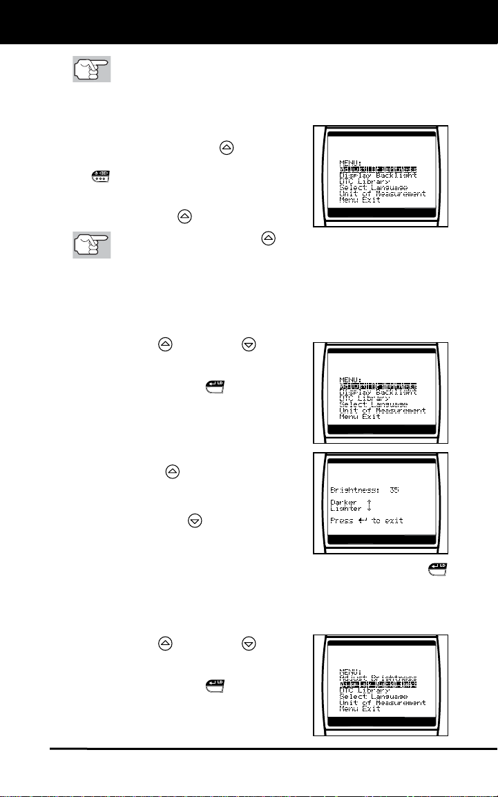
Adjusting Display Brightness
1. Use the UP and DOWN buttons,
as necessary, to highlight Adjust
Brightness in the Setup Menu, then
press the ENTER/LD
The Adjust Brightness screen
displays.
The Brightness field shows the current
brightness setting, from 0 to 43.
2. Press the UP
button to decrease the
brightness of the display (make the
display darker).
3. Press the DOWN
the brightness of the display (make the
display lighter).
4. When the desired brightness is obtained, press the ENTER/LD
button to save your changes and return to the Setup Menu.
button, then
button until the Setup Menu is
button.
button to increase
Using the Backlight
1. Use the UP
and DOWN buttons,
as necessary, to highlight Display
Backlight in the Setup Menu, then
press the ENTER/LD
The Display Backlight screen dis-
button.
plays.
6 CanOBD2&1
About the CanOBD2&1 Scan Tool
ADJUSTMENTS/SETTINGS AND DTC LIBRARY
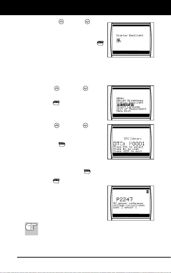
2. Press the UP or DOWN button,
as necessary, to select the desired
backlight mode, either ON or OFF.
3. When the desired backlight mode is
selected, press the ENTER/LD
button to save your changes.
The display returns to the MENU,
and the backlight turns “on” or “off”
as selected.
Searching for a DTC Definition Using the DTC Library (applicable
to OBD2 systems only)
1. Use the UP
and DOWN buttons,
as necessary, to highlight DTC Library
in the Setup Menu, then press the
ENTER/LD
The Enter DTC screen displays. The
button.
screen shows the code “P0001”,
with the “P” flashing.
2. Use the UP
and DOWN buttons,
as necessary, to scroll to the desired
DTC type (P=Powertrain, U=Network,
B=Body, C=Chassis), then press the
DTC SCROLL
The selected character displays
button.
“solid”, and the next character
begins flashing.
3. Select the remaining characters in the DTC in the same way,
pressing the DTC SCROLL
button to confirm each character.
When you have selected all the DTC characters, press the
ENTER/LD
If you entered a “Generic” DTC
button to view the DTC definition.
(DTCs that start with “P0”, “P2” and
some “P3”):
- The selected DTC and DTC
definition (if available), show on
the CanOBD2&1 Scan Tool’s
display.
If a definition for the DTC you entered is not available, an
advisory message shows on the CanOBD2&1 Scan Tool’s
display.
If you entered a “Manufacturer-Specific” DTC (DTCs that start
with “P1” and some “P3”):
CanOBD2&1 7
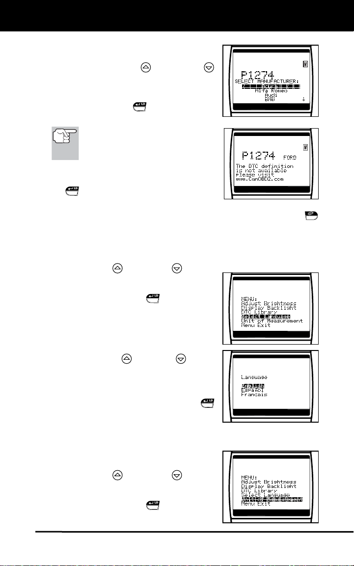
About the CanOBD2&1 Scan Tool
ADJUSTMENTS/SETTINGS AND DTC LIBRARY
- The “Select Manufacturer” screen
displays.
- Use the UP
buttons, as necessary, to
highlight the appropriate
manufacturer, then press the
ENTER/LD
the correct DTC for your vehicle.
If a definition for the DTC you
entered is not available, an
advisory message shows on the
CanOBD2&1 Scan Tool’s display.
4. If you wish to view definitions for
additional DTCs, press the ENTER/LD
button to return to the DTC Library
screen, and repeat steps 2 and 3.
5. When all desired DTCs have been viewed, press the ERASE
button to exit the DTC Library and return to the Setup Menu.
Selecting the Display Language
and DOWN
button to display
1. Use the UP
and DOWN buttons,
as necessary, to highlight Select
Language in the Setup Menu, then
press the ENTER/LD
The Select Language screen dis-
button.
plays.
The currently selected display
Language is highlighted.
2. Press the UP
or DOWN button,
as necessary, to highlight the desired
display language.
3. When the desired display language is
highlighted, press the ENTER/LD
button to save your changes and return
to the Setup Menu (shown in the
selected display language).
Setting the Unit of Measurement
1. Use the UP
and DOWN buttons,
as necessary, to highlight Unit of
Measure in the Setup Menu, then
press the ENTER/LD
button.
8 CanOBD2&1

About the CanOBD2&1 Scan Tool
ADJUSTMENTS/SETTINGS AND DTC LIBRARY
2. Press the UP or DOWN button,
as necessary, to highlight the desired
Unit of Measure.
3. When the desired Unit of Measure
value is selected, press the ENTER/LD
button to save your changes and
return to the Setup Menu.
Exiting the MENU Mode
1. Use the UP
and DOWN buttons, as necessary, to highlight
Menu Exit in the Setup Menu, then press the ENTER/LD
button.
If diagnostic data IS currently stored in the CanOBD2&1 Scan
Tool’s memory, the stored data is shown on the display.
If diagnostic data IS NOT currently stored in the CanOBD2&1
Scan Tool’s memory, the “Linking Instructions” screen is shown
on the display.
CanOBD2&1 9
CanOBD2&1 Scan Tool Controls
CONTROLS AND INDICATORS
CONTROLS AND INDICATORS
11
7
6
1
2
5
10
8
9
3
4
16
12
13 14
15
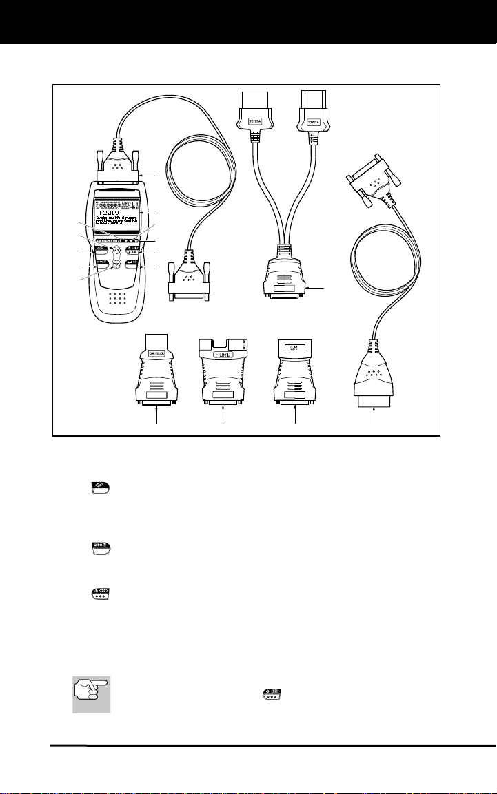
Figure 1. Controls and Indicators
See Figure 1 for the locations of items 1 through 16, below.
1.
ERASE button - Erases Diagnostic Trouble Codes (DTCs), and
“Freeze Frame” data from your vehicle’s computer, and resets
Monitor status. (“Freeze Frame” data and Monitor status are
applicable to OBD2 systems only.)
DTC SCROLL button - Displays the DTC View screen and/or
2.
scrolls the LCD display to view DTCs when more than one DTC is
present.
3.
POWER/LINK button - When the CanOBD2&1 Scan Tool IS
NOT connected to a vehicle, turns the CanOBD2&1 Scan Tool “On”
and “Off”. When the CanOBD2&1 Scan Tool is connected to a
vehicle, links the CanOBD2&1 Scan Tool to the vehicle’s PCM to
retrieve diagnostic data from the computer’s memory. (The LINK
function is applicable to OBD2 systems only.)
To turn the CanOBD2&1 Scan Tool "On", you must press and
hold the POWER/LINK
button for approximately 3
seconds.
10 CanOBD2&1

CanOBD2&1 Scan Tool Controls
CONTROLS AND INDICATORS
4. ENTER/LIVE DATA button - When in MENU mode, confirms
the selected option or value. When linked to a vehicle, places the
CanOBD2&1 Scan Tool in "Live Data" mode.
5.
DOWN button - When in MENU mode, scrolls DOWN through
the menu and submenu selection options. When retrieving and
viewing DTCs, scrolls down through the current display screen to
display any additional data.
6.
UP button - When in MENU mode, scrolls UP through the menu
and submenu selection options. When retrieving and viewing DTCs,
scrolls ups through the current display screen to display any
additional data.
7. GREEN LED - Indicates that all engine systems are running
normally (all Monitors on the vehicle are active and performing their
diagnostic testing, and no DTCs are present). (Monitors are
applicable to OBD2 systems only.)
8. YELLOW LED - Indicates there is a possible problem. A “Pending”
or a history DTC is present and/or some of the vehicle’s emission
monitors have not run their diagnostic testing. (Monitors and
pending DTCs are applicable to OBD2 systems only.)
9. RED LED - Indicates there is a problem in one or more of the
vehicle’s systems. The red LED is also used to show that DTC(s)
are present. DTCs are shown on the CanOBD2&1 Scan Tool’s
display. In this case, the Malfunction Indicator (“Check Engine”)
lamp on the vehicle’s instrument panel will light steady on.
10. Display - Displays Setup Menu and submenus, test results,
CanOBD2&1 Scan Tool functions and Monitor status information.
See DISPLAY FUNCTIONS, on next page, for more details.
(Monitors are applicable to OBD2 systems only.)
11. Cable - Connects the CanOBD2&1 Scan Tool to the vehicle’s Data
Link Connector (DLC) when retrieving codes from OBD I systems
(used with items 12, 13, 14 and 16).
12. CHRYSLER Connector Cable Adaptor - Installs on cable (item 11)
when connecting to a Chrysler OBD1 Data Link Connector.
13. FORD Connector Cable Adaptor - Installs on cable (item 11) when
connecting to a Ford OBD1 Data Link Connector.
14. GM Connector Cable Adaptor - Installs on cable (item 11) when
connecting to a GM OBD1 Data Link Connector.
15. OBD II Cable - Connects the CanOBD2&1 Scan Tool to the
vehicle's Data Link Connector (DLC) when retrieving codes from
OBD II systems.
16. TOYOTA Connector Cable Adaptor - Installs on cable (item 11)
when connecting to a Toyota OBD1 Data Link Connector.
CanOBD2&1 11
CanOBD2&1 Scan Tool Controls
DISPLAY FUNCTIONS
DISPLAY FUNCTIONS
12 13
21
11
3
4
5
6
7
8
15
16
14
10
9
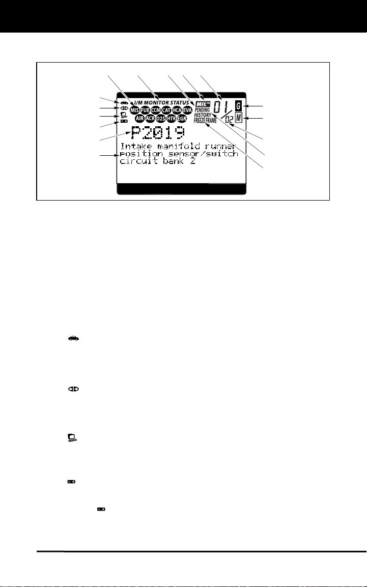
Figure 2. Display Functions
See Figure 2 for the locations of items 1 through 16, following.
1. I/M MONITOR STATUS field - Identifies the I/M Monitor status area.
(This function is applicable to OBD2 systems only.)
2. Monitor icons - Indicate which Monitors are supported by the
vehicle under test, and whether or not the associated Monitor has
run its diagnostic testing (Monitor status). When a Monitor icon is
solid, it indicates that the associated Monitor has completed its
diagnostic testing. When a Monitor icon is flashing, it indicates that
the vehicle supports the associated Monitor, but the Monitor has not
yet run its diagnostic testing. (This function is applicable to OBD2
systems only.)
3.
Vehicle icon - Indicates whether or not the CanOBD2&1
Scan Tool is being properly powered through the vehicle’s Data
Link Connector (DLC). A visible icon indicates that the
CanOBD2&1 Scan Tool is being powered through the vehicle’s
DLC connector.
4.
Link icon - Indicates whether or not the CanOBD2&1 Scan Tool
is communicating (linked) with the vehicle’s on-board computer.
When visible, the CanOBD2&1 Scan Tool is communicating with the
computer. If the Link icon is not visible, the CanOBD2&1 Scan Tool
is not communicating with the computer.
5.
Computer icon - When this icon is visible it indicates that the
CanOBD2&1 Scan Tool is linked to a personal computer. An
optional “PC Link Kit” is available that makes it possible to upload
retrieved data to a personal computer.
6.
CanOBD2&1 Scan Tool Internal Battery icon - When visible,
indicates the CanOBD2&1 Scan Tool batteries are “low” and should
be replaced. If the batteries are not replaced when the battery
symbol
is "on", all 3 LEDs will light up as a last resort indicator to
warn you that the batteries need replacement. No data will be
displayed on screen when all 3 LEDs are lit.
12 CanOBD2&1
CanOBD2&1 Scan Tool Controls
VIEWING DTCs IN THE CANOBD2&1 SCAN TOOL’S MEMORY
7. DTC Display Area - Displays the Diagnostic Trouble Code (DTC)
number. Each fault is assigned a code number that is specific to that
fault.
8. Test Data Display Area - Displays DTC definitions, Freeze Frame
data, and other pertinent test information messages.
9. FREEZE FRAME icon - Indicates that there is Freeze Frame data
from “Priority Code” (Code #1) stored in the vehicle’s computer
memory.
10. HISTORY icon - Indicates the currently displayed DTC is a “History”
code.
11. PENDING icon - Indicates the currently displayed DTC is a
“Pending” code.
12. MIL icon - Indicates the status of the Malfunction Indicator Lamp
(MIL). The MIL icon is visible only when a DTC has commanded the
MIL on the vehicle’s dashboard to light.
13. Code Number Sequence - The CanOBD2&1 Scan Tool assigns a
sequence number to each DTC that is present in the computer’s
memory, starting with “01.” This number indicates which code is
currently displayed. Code number “01” is always the highest priority
code, and the one for which “Freeze Frame” data has been stored.
(Freeze Frame data is applicable to OBD2 systems only.)
If “01” is a “Pending” code, there may or may not be “Freeze
Frame” data stored in memory.
14. Code Enumerator - Indicates the total number of codes retrieved
from the vehicle’s computer.
15.
Generic DTC icon - When visible, indicates that the currently
displayed DTC is a “Generic” or “Universal” code. (This function is
applicable to OBD2 systems only.)
16.
Enhanced DTC icon - When visible, indicates that the currently
displayed DTC is a Manufacturer Specific Code. (This function is
applicable to OBD2 systems only.)
VIEWING DTCs IN THE CANOBD2&1 SCAN TOOL’S
MEMORY
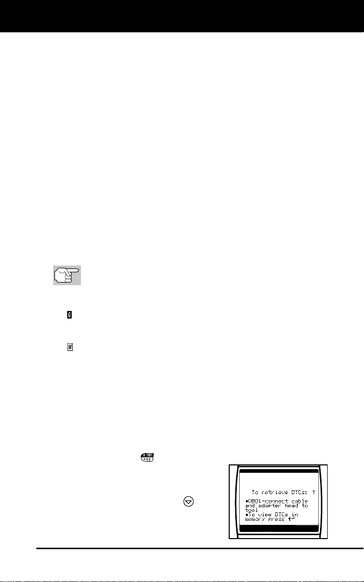
To view DTC’s and other diagnostic data stored in the CanOBD2&1
Scan Tool’s memory, do the following:
1. With no DLC cable connected to the CanOBD2&1 Scan Tool, press
the POWER/LINK
button to turn the CanOBD2&1 Scan Tool
“on”.
The “To Retrieve DTCs” screen
shows on the CanOBD2&1 Scan
Tool’s display. Press the
button
for instructions to view DTC’s in
memory.
CanOBD2&1 13
CanOBD2&1 Scan Tool Controls
VIEWING DTCs IN THE CANOBD2&1 SCAN TOOL’S MEMORY
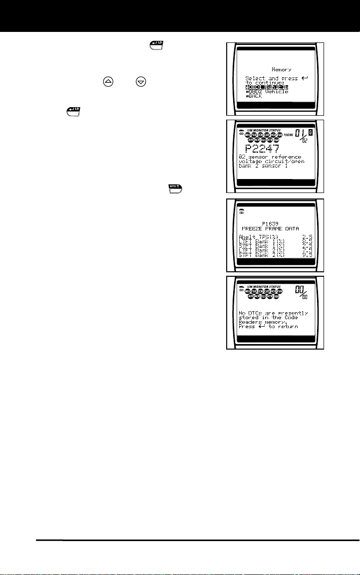
2. Press the ENTER/LD button.
The “Select OBD System” screen
displays.
3. Use the
and select your vehicle’s OBD system
(OBD1 or OBD2). Press the ENTER/LD
button to continue.
Select “Back” if you wish to return to
the Main Menu.
4. If DTCs are present in the CanOBD2&1
Scan Tool’s memory, the first stored
DTC will display on the screen.
If more than one DTC is present,
use the DTC SCROLL
scroll through the DTC’s.
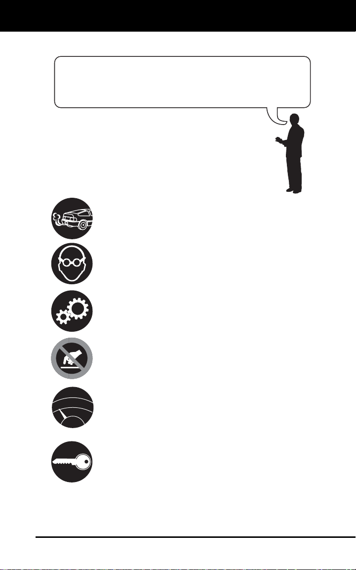
5. For OBD2 systems only - Freeze
Frame Data (if available) will display
after DTC #1.
and keys to highlight
button to
6. If no DTCs are in the CanOBD2&1 Scan
Tool’s memory, a “No DTC’s are
presently stored in the Code Readers
memory” message displays.
14 CanOBD2&1

Preparation for Testing
PRELIMINARY VEHICLE DIAGNOSTIC WORKSHEET
PRELIMINARY VEHICLE DIAGNOSTIC WORKSHEET
The purpose of this form is to help you gather preliminary information on
your vehicle before you retrieve codes. By having a complete account of
your vehicle's current problem(s), you will be able to systematically
pinpoint the problem(s) by comparing your answers to the fault codes
you retrieve. You can also provide this information to your mechanic to
assist in diagnosis and help avoid costly and unnecessary repairs. It is
important for you to complete this form to help you and/or your
mechanic have a clear understanding of your vehicle's problems.
NAME:
DATE:
VIN*:
YEAR:
MAKE:
MODEL:
ENGINE SIZE:
VEHICLE MILEAGE:
*VIN: Vehicle Identification Number, found at the base of the windshield
on a metallic plate, or at the driver door latch area (consult your vehicle
owner's manual for location).
TRANSMISSION:
❏ Automatic
❏ Manual
Please check all applicable items in each category.
DESCRIBE THE PROBLEM:
CanOBD2&1 15

Preparation for Testing
PRELIMINARY VEHICLE DIAGNOSTIC WORKSHEET
WHEN DID YOU FIRST NOTICE THE PROBLEM:
❏ Just Started
❏ Started Last Week
❏ Started Last Month
❏ Other:
m
LIST ANY REPAIRS DONE IN THE PAST SIX MONTHS:
PROBLEMS STARTING
❏ No symptoms
❏ Will not crank
ENGINE QUITS OR STALLS
❏ No symptoms
❏ Right after starting
❏ When shifting into gear
❏ During steady-speed
driving
❏ Cranks, but will not start
❏ Starts, but takes a long
time
❏ Right after vehicle
comes to a stop
❏ While idling
❏ During acceleration
❏ When parking
IDLING CONDITIONS
❏ No symptoms
❏ Is too slow at all times
❏ Is too fast
❏ Is sometimes too fast or
too slow
❏ Is rough or uneven
❏ Fluctuates up and down
RUNNING CONDITIONS
❏ No symptoms
❏ Runs rough
❏ Lacks power
❏ Bucks and jerks
❏ Poor fuel economy
❏ Hesitates or stumbles on
❏ Backfires
❏ Misfires or cuts out
❏ Engine knocks, pings or
rattles
❏ Surges
❏ Dieseling or run-on
accelerations
16 CanOBD2&1

Preparation for Testing
PRELIMINARY VEHICLE DIAGNOSTIC WORKSHEET
AUTOMATIC TRANSMISSION PROBLEMS (if applicable)
❏ No symptoms
❏ Shifts too early or too late
❏ Changes gear incorrectly
PROBLEM OCCURS
❏ Morning ❏ Afternoon ❏ Anytime
ENGINE TEMPERATURE WHEN PROBLEM OCCURS
❏ Cold ❏ Warm ❏ Hot
DRIVING CONDITIONS WHEN PROBLEM OCCURS
❏ Short - less than 2 miles
❏ 2 - 10 miles
❏ Long - more than 10 miles
❏ Stop and go
❏ While turning
❏ While braking
❏ At gear engagement
❏ With A/C operating
DRIVING HABITS
❏ Mostly city driving
❏ Highway
❏ Park vehicle inside
❏ Park vehicle outside
GASOLINE USED
❏ 87 Octane
❏ 89 Octane
WEATHER CONDITIONS WHEN PROBLEM OCCURS
❏ 32 - 55° F (0 - 13° C)
❏ Below freezing (32° F / 0° C)
CHECK ENGINE LIGHT / DASH WARNING LIGHT
❏ Sometimes ON ❏ Always ON ❏ Never ON
PECULIAR SMELLS
❏ "Hot"
❏ Sulfur ("rotten egg")
❏ Burning rubber
STRANGE NOISES
❏ Rattle
❏ Knock
❏ Vehicle does not move
when in gear
❏ Jerks or bucks
❏ With headlights on
❏ During acceleration
❏ Mostly driving downhill
❏ Mostly driving uphill
❏ Mostly driving level
❏ Mostly driving curvy
roads
❏ Mostly driving rough
roads
❏ Drive less than 10 miles per day
❏ Drive 10 to 50 miles per day
❏ Drive more than 50 miles per
day
❏ 91 Octane
❏ More than 91 Octane
❏ Above 55° F (13° C)
❏ Gasoline
❏ Burning oil
❏ Electrical
❏ Squeak
❏ Other
CanOBD2&1 17

Preparation for Testing
BEFORE YOU BEGIN
BEFORE YOU BEGIN
The Enhanced CanOBD2&1 Scan
Tool aids in monitoring electronicand emissions-related faults in
your vehicle and retrieving fault
codes related to malfunctions in
these systems. Mechanical problems such as low oil level or
damaged hoses, wiring or electrical connectors can cause poor engine
performance and may also cause a fault code to set. Fix any known
mechanical problems before performing any test. See your vehicle’s service
manual or a mechanic for more information.
Check the following areas before starting any test:
Check the engine oil, power steering fluid, transmission fluid (if
applicable), engine coolant and other fluids for proper levels. Top off
low fluid levels if needed.
Make sure the air filter is clean and in good condition. Make sure all
air filter ducts are properly connected. Check the air filter ducts for
holes, rips or cracks.
Make sure all engine belts are in good condition. Check for cracked,
torn, brittle, loose or missing belts.
Make sure mechanical linkages to engine sensors (throttle, gearshift
position, transmission, etc.) are secure and properly connected. See
your vehicle’s service manual for locations.
Check all rubber hoses (radiator) and steel hoses (vacuum/fuel) for
leaks, cracks, blockage or other damage. Make sure all hoses are
routed and connected properly.
Make sure all spark plugs are clean and in good condition. Check
for damaged, loose, disconnected or missing spark plug wires.
Make sure the battery terminals are clean and tight. Check for
corrosion or broken connections. Check for proper battery and
charging system voltages.
Check all electrical wiring and harnesses for proper connection.
Make sure wire insulation is in good condition, and there are no bare
wires.
Make sure the engine is mechanically sound. If needed, perform a
compression check, engine vacuum check, timing check (if
applicable), etc.
18 CanOBD2&1
Preparation for Testing
VEHICLE SERVICE MANUALS
VEHICLE SERVICE MANUALS
Always refer to the manufacturer’s service manual for your vehicle
before performing any test or repair procedures. Contact your local car
dealership, auto parts store or bookstore for availability of these
manuals. The following companies publish valuable repair manuals:
Haynes Publications
861 Lawrence Drive
Newbury Park, California 91320
Phone: 800-442-9637
Mitchell International
14145 Danielson Street
Poway, California 92064
Phone: 888-724-6742
Motor Publications
5600 Crooks Road, Suite 200
Troy, Michigan 48098
Phone: 800-426-6867
FACTORY SOURCES
Ford, GM, Chrysler, Honda, Isuzu, Hyundai and Subaru Service
Manuals
Helm Inc.
14310 Hamilton Avenue
Highland Park, Michigan 48203
Phone: 800-782-4356
CanOBD2&1 19

General Code Retrieval Procedures
OBD1 SYSTEMS / OBD2 SYSTEMS
Procedures for Retrieving Diagnostic Trouble Codes from OBD1
systems are vehicle manufacturer specific. Each manufacturer uses
their own procedure.
Procedures for retrieving Diagnostic Trouble Codes from OBD2 systems
are generic, and apply to all vehicles equipped with OBD2 systems.
From the following list, select the procedure that applies to your
vehicle’s OBD system, and proceed to appropriate section for detailed
code retrieval procedures.
OBD1 SYSTEMS
Most cars and light trucks (under 8500 GW) sold in the U.S. from early
1980’s to 1995 are equipped with what is known as the first generation
of On-Board Diagnostics or “OBD1”.
If your Chrysler/Jeep, Ford, GM or Toyota vehicle, (1995 and older)
is equipped with an ‘OBD1 System”, proceed to the proper section
as indicated below, for a detailed application list and code retrieval
procedures:
CHRYSLER/JEEP .............................page 68
FORD................................................. page 74
GM .....................................................page 97
TOYOTA ............................................page 103
OBD2 SYSTEMS
ALL 1996 and newer cars and light trucks (under 8500 GW) sold in the
U.S. are equipped with what is known as the second generation of OnBoard Diagnostics or “OBD2”.
If your vehicle (1996 and newer) is equipped with an “OBD2
System”, proceed to the OBD2 SYSTEMS section on page 20 for a
detailed application list, code retrieval procedures, Monitor status,
and Freeze Frame data information.
20 CanOBD2&1
OBD2 Systems
VEHICLES COVERED
VEHICLES COVERED
The Enhanced CanOBD2&1 Scan Tool is designed to work on all OBD2
compliant vehicles. All 1996 and newer vehicles (cars and light trucks)
sold in the United States are OBD2 compliant.
Federal law requires that all 1996 and newer cars and light
trucks sold in the United States must be OBD2 compliant; this
includes all Domestic, Asian and European vehicles.
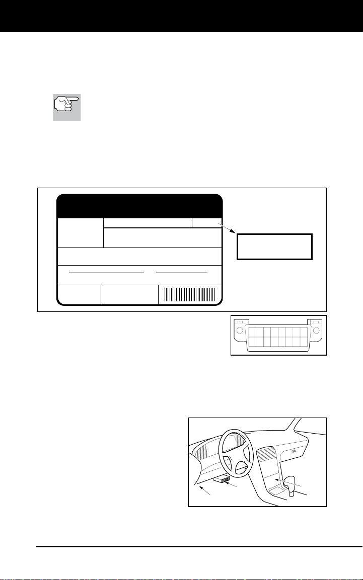
Some 1994 and 1995 vehicles are OBD2 compliant. To find out if a
1994 or 1995 vehicle is OBD2 compliant, check the following:
1. The Vehicle Emissions Control Information (VECI) Label. This
label is located under the hood or by the radiator of most vehicles. If
the vehicle is OBD2 compliant, the label will state “OBD II
Certified.”
VEHICLE EMISSION CONTROL INFORMATION
VEHICLE
MANUFACTURER
REFER TO SERVICE MANUAL FOR ADDITIONAL INFORMATION
TUNE-UP CONDITIONS: NORMAL OPERATING ENGINE TEMPERATURE,
ACCESSORIES OFF, COOLING FAN OFF, TRANSMISSION IN NEUTRAL
EXHAUST EMISSIONS STANDARDS STANDARD CATEGORY
CERTIFICATION
IN-USE
SPARK PLUG
TYPE NGK BPRE-11
GAP: 1.1MM
ENGINE FAMILY EFN2.6YBT2BA
DISPLACEMENT 2.6L
THIS VEHICLE CONFORMS TO U.S. EPA AND STATE
OF CALIFORNIA REGULATIONS APPLICABLE TO
1999 MODEL YEAR NEW TLEV PASSENGER CARS.
TLEV
TLEV INTERMEDIATE
OBD II
CERTIFIED
CATALYST
OBD II
CERTIFIED
2. Government Regulations require that all
OBD2 compliant vehicles must have a
“common” sixteen-pin Data Link
Connector (DLC).
12345678
9 10111213141516
Some 1994 and 1995 vehicles have 16-pin connectors but are not
OBD2 compliant. Only those vehicles with a Vehicle Emissions Control
Label stating “OBD II Certified” are OBD2 compliant.
Data Link Connector (DLC) Location
The 16-pin DLC is usually
located under the instrument
panel (dash), within 12 inches
(300 mm) of center of the panel,
on the driver’s side of most
vehicles. It should be easily
accessible and visible from a
kneeling position outside the
vehicle with the door open.
LEFT CORNER
OF DASH
NEAR
CENTER
OF DASH
BEHIND
ASHTRAY
CanOBD2&1 21
OBD2 Systems
DIAGNOSTIC TROUBLE CODES (DTCs)
On some Asian and European vehicles the DLC is located
behind the “ashtray” (the ashtray must be removed to
access it) or on the far left corner of the dash. If the DLC
cannot be located, consult the vehicle’s service manual for
the location.
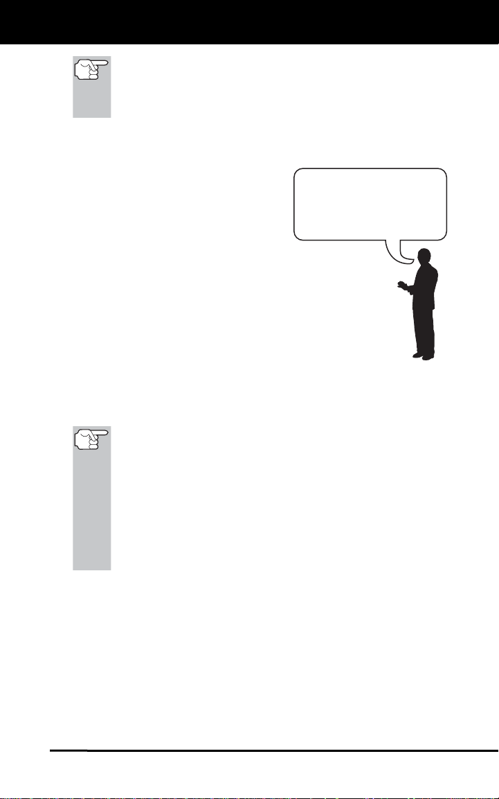
DIAGNOSTIC TROUBLE CODES (DTCs)
Diagnostic Trouble Codes (DTCs) are
meant to guide you to the proper
service procedure in the vehicle’s
service manual. DO NOT replace parts
based only on DTCs without first
consulting the vehicle’s service manual
Diagnostic Trouble
Codes (DTCs) are
codes that identify a
specific problem area.
for proper testing procedures for that
particular system, circuit or component.
DTCs are alphanumeric codes that are used to identify a
problem that is present in any of the systems that are
monitored by the on-board computer (PCM). Each trouble
code has an assigned message that identifies the circuit,
component or system area where the problem was found.
OBD2 diagnostic trouble codes are made up of five characters:
The 1st character is a letter. It identifies the “main system” where
the fault occurred (Body, Chassis, Powertrain, or Network).
The 2nd character is a numeric digit. It identifies the “type” of code
(Generic or Manufacturer-Specific).
Generic DTCs are codes that are used by all vehicle
manufacturers. The standards for generic DTCs, as well as
their definitions, are set by the Society of Automotive
Engineers (SAE).
Manufacturer-Specific DTCs are codes that are controlled by
the vehicle manufacturers. The Federal Government does not
require vehicle manufacturers to go beyond the standardized
generic DTCs in order to comply with the new OBD2
emissions standards. However, manufacturers are free to
expand beyond the standardized codes to make their systems
easier to diagnose.
The 3rd character is a numeric digit. It identifies the specific
system or sub-system where the problem is located.
The 4th and 5th characters are numeric digits. They identify the
section of the system that is malfunctioning.
22 CanOBD2&1
OBD2 Systems
DIAGNOSTIC TROUBLE CODES (DTCs)
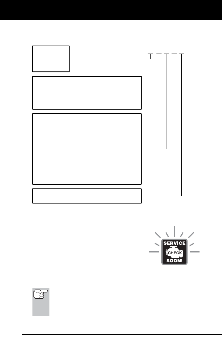
P0201 - Injector Circuit Malfunction, Cylinder 1
OBD2 DTC EXAMPLE
B
-
Body
C
-
Chassis
P
-
Powertrain
U
-
Network
-
Generic
0
-
Manufacturer Specific
1
-
Generic
2
-
Includes both Generic and Manufacturer
3
Specific Codes
Identifies the system where the
problem is located:
1
-
Fuel and Air Metering
2
-
Fuel and Air Metering (injector circuit
malfunction only)
3
-
Ignition System or Misfire
4
-
Auxiliary Emission Control System
5
-
Vehicle Speed Control and Idle Control
System
6
-
Computer Output Circuits
7
-
Transmission
8
-
Transmission
Identifies what section of the system
is malfunctioning
P 0 2 0 1
DTCs and MIL Status
When the vehicle’s on-board computer detects
a failure in an emissions-related component or
system, the computer’s internal diagnostic
program assigns a diagnostic trouble code
(DTC) that points to the system (and subsystem)
where the fault was found. The diagnostic
program saves the code in the computer’s
memory. It records a “Freeze Frame” of conditions present when the
fault was found, and lights the Malfunction Indicator Lamp (MIL). Some
faults require detection for two trips in a row before the MIL is turned on.
The “Malfunction Indicator Lamp” (MIL) is the accepted term
used to describe the lamp on the dashboard that lights to warn
the driver that an emissions-related fault has been found.
Some manufacturers may still call this lamp a “Check Engine”
or “Service Engine Soon” light.
CanOBD2&1 23
OBD2 Systems
CODE RETRIEVAL PROCEDURE
CODE RETRIEVAL PROCEDURE
Retrieving and using Diagnostic Trouble Codes (DTCs) for
troubleshooting vehicle operation is only one part of an
overall diagnostic strategy.
Never replace a part based only on the DTC definition.
Each DTC has a set of testing procedures, instructions
and flow charts that must be followed to confirm the
location of the problem. This information is found in the
vehicle's service manual. Always refer to the vehicle's
service manual for detailed testing instructions.
Check your vehicle thoroughly before performing
any test. See BEFORE YOU BEGIN on page 18
for details.
ALWAYS observe safety precautions whenever working on a
vehicle. See Safety Precautions on page 3 for more
information.
1. Turn the ignition OFF.
2. Locate the vehicle's 16-pin Data Link
Connector (DLC). See page 21 for
connector location.
Some DLCs have a plastic cover
that must be removed before
connecting the CanOBD2&1 Scan
Tool cable connector.
If the CanOBD2&1 Scan Tool is ON,
turn it OFF by pressing the
POWER/LINK
connecting the CanOBD2&1 Scan
Tool to the DLC.
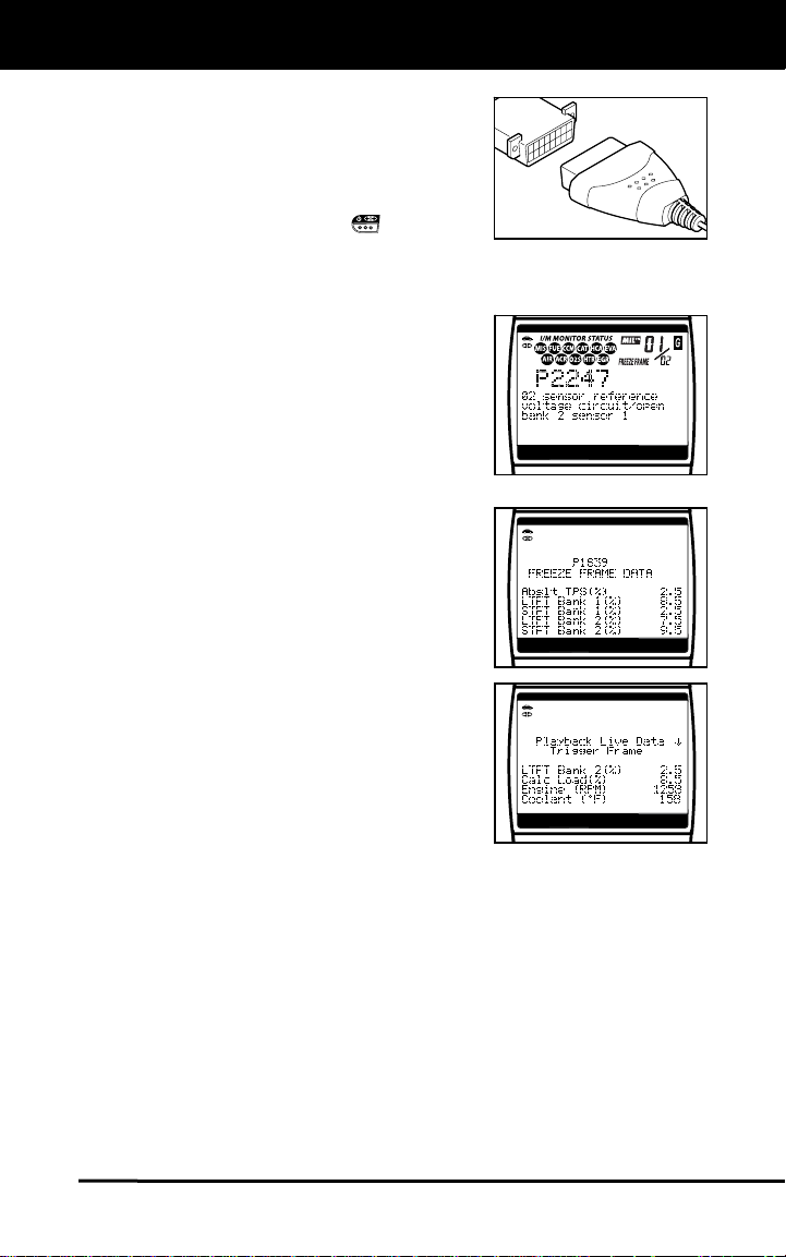
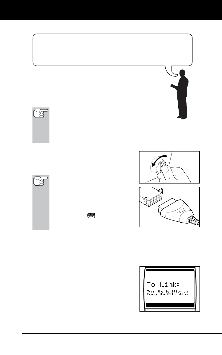
3. Connect the OBD II Cable to the CanOBD2&1 Scan Tool, then
connect to the vehicle’s DLC.
If you have problems connecting the cable connector to the DLC,
rotate the connector 180° and try again.
If you still have problems, check the
pins on the CanOBD2&1 Scan
Tool’s DLC and on the vehicle’s
DLC.
4. When the CanOBD2&1 Scan Tool’s
cable connector is properly connected
to the vehicle’s DLC, the unit automatically turns ON, and the display shows
instructions for linking to the vehicle’s
on-board computer.
button BEFORE
24 CanOBD2&1
OBD2 Systems
CODE RETRIEVAL PROCEDURE
If the unit does not power on automatically when connected to
the vehicle’s DLC connector, it usually indicates there is no
power present at the vehicle’s DLC connector. Check your fuse
panel and replace any burned-out fuses.
If replacing the fuse(s) does not correct the problem, consult
your vehicle’s repair manual to identify the proper computer
(PCM) fuse/circuit, and perform any necessary repairs before
proceeding.
5. Turn the ignition on. DO NOT start the engine.
6. Press and release the CanOBD2&1 Scan Tool’s POWER/LINK
button.
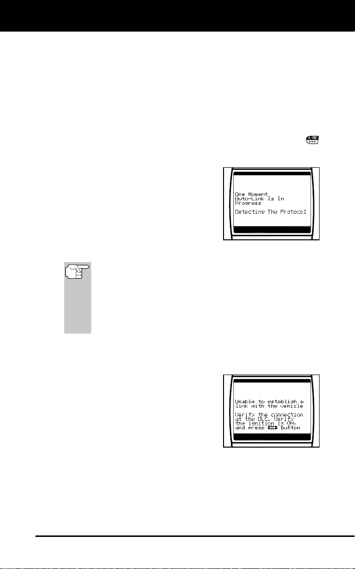
The CanOBD2&1 Scan Tool will
automatically start a check of the
vehicle’s computer to determine
which type of communication
protocol it is using. When the
CanOBD2&1 Scan Tool identifies
the computer’s communication
protocol, a communication link is established. The protocol type used by
the vehicle’s computer is shown on
the display.
A PROTOCOL is a set of rules and procedures for
regulating data transmission between computers, and
between testing equipment and computers. As of this
writing, five different types of protocols (ISO 9141, Keyword
2000, J1850 PWM, J1850 VPW and CAN) are in use by
vehicle manufacturers. The CanOBD2&1 Scan Tool
automatically identifies the protocol type and establishes a
communication link with the vehicle’s computer.
7. After approximately 10~60 seconds, the CanOBD2&1 Scan Tool will
retrieve and display any Diagnostic Trouble Codes, Monitor Status
and Freeze Frame Data retrieved from the vehicle’s computer
memory.
If the CanOBD2&1 Scan Tool fails
to link to the vehicle’s computer a
“Linking Failed” message shows on
the CanOBD2&1 Scan Tool’s
display.
- Verify the connection at the DLC
and verify the ignition is ON.
- Turn the ignition OFF, wait 5 seconds, then turn back ON to
reset the computer.
- Ensure your vehicle is OBD2 compliant. See VEHICLES
COVERED on page 21 for vehicle compliance verification
information.
CanOBD2&1 25
OBD2 Systems
CODE RETRIEVAL PROCEDURE
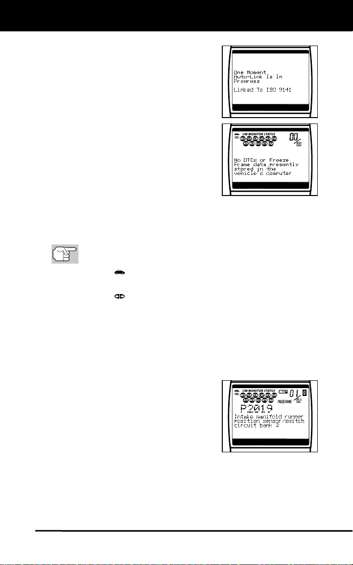
The CanOBD2&1 Scan Tool will
automatically re-link to the vehicle’s
computer every 30 seconds to
refresh the data being retrieved.
When data is being refreshed, the
message “One moment Auto – link
in progress” is shown on the display.
This action repeats as long as the
CanOBD2&1 Scan Tool is
communicating with the vehicle’s
computer.
The CanOBD2&1 Scan Tool will
display a code only if codes are
present in the vehicle’s computer
memory. If no codes are present, a
“No DTC’s are presently stored in
the vehicle’s computer” message is
displayed.
The CanOBD2&1 Scan Tool is capable of retrieving and storing
up to 32 codes in memory, for immediate or later viewing.
8. To read the display:
Refer to DISPLAY FUNCTIONS on page 12 for a description
of display elements.
A visible icon indicates that the CanOBD2&1 Scan Tool is
being powered through the vehicle’s DLC connector.
A visible icon indicates that the CanOBD2&1 Scan Tool is
linked to (communicating with) the vehicle’s computer.
The I/M Monitor Status icons indicate the type and number of
Monitors the vehicle supports, and provide indications of the
current status of the vehicle’s Monitors. A solid Monitor icon
indicates the associated Monitor has run and completed its
testing. A blinking Monitor icon indicates the associated Monitor
has not run and completed its testing.
The upper right hand corner of the
display shows the number of the
code currently being displayed, the
total number of codes retrieved, the
type of code (G = Generic; M =
Enhanced or Manufacturer specific),
and whether or not the displayed
code commanded the MIL on. If the
code being displayed is a PENDING
code, the PENDING icon is shown.
The Diagnostic Trouble Code (DTC) and related code definition
are shown in the lower section of the display.
26 CanOBD2&1
OBD2 Systems
CODE RETRIEVAL PROCEDURE
In the case of long code definitions, or when viewing
Freeze Frame data, a small arrow is shown in the
upper/lower right-hand corner of the code display area
to indicate the presence of additional information. Use
the
additional information.
If a definition for the currently displayed code is not
available, an advisory message shows on the
CanOBD2&1 Scan Tool’s display.
9. Read and interpret Diagnostic Trouble Codes/system condition
using the display and the green, yellow and red LEDs.
The green, yellow and red LEDs are used (with the LCD
display) as visual aids to make it easier to determine
engine system conditions.
Green LED – Indicates that all
engine systems are “OK” and
operating normally. All Monitors
supported by the vehicle have run
and performed their diagnostic
testing, and no trouble codes are
present. A zero will show on the
CanOBD2&1 Scan Tool’s display,
and all Monitor icons will be solid.
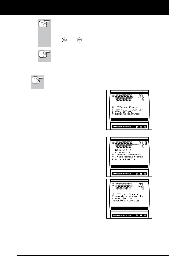
Yellow LED – Indicates one of the following conditions:
A. A PENDING CODE IS PRESENT –
If the yellow LED is illuminated, it
may indicate a Pending code is
present. Check the CanOBD2&1
Scan Tool’s display for confirmation.
A Pending code is confirmed by the
presence of a numeric code and the
word PENDING on the CanOBD2&1
Scan Tool’s display.
B. MONITOR NOT RUN STATUS – If
the CanOBD2&1 Scan Tool’s
display shows a zero (indicating
there are no DTC’s present in the
vehicle’s computer memory), but the
yellow LED is illuminated, it may be
an indication that some of the
Monitors supported by the vehicle
have not yet run and completed
their diagnostic testing. Check the
CanOBD2&1 Scan Tool’s display for confirmation. All Monitor
icons that are blinking have not yet run and completed their
diagnostic testing; all Monitor icons that are solid have run and
completed their diagnostic testing.
and buttons, as necessary, to view the
CanOBD2&1 27
OBD2 Systems
CODE RETRIEVAL PROCEDURE
Red LED – Indicates there is a
problem with one or more of the
vehicle’s systems. The red LED is
also used to indicate that DTC(s)
are present (displayed on the
CanOBD2&1 Scan Tool’s screen).
In this case, the Malfunction
Indicator (Check Engine) lamp on
the vehicle’s instrument panel will
be illuminated.
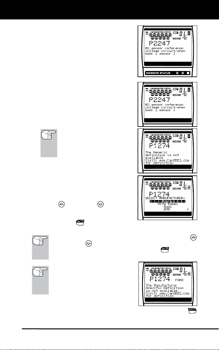
DTC’s that start with “P0”, “P2” and
some “P3” are considered Generic
(Universal). All Generic DTC
definitions are the same on all
OBD2 equipped vehicles. The
CanOBD2&1 Scan Tool
automatically displays the code
definitions for Generic DTC’s.
If the Generic definition for the
currently displayed code is not
available, an advisory message
shows on the CanOBD2&1 Scan
Tool’s display.
DTC’s that start with “P1” and some
“P3” are Manufacturer specific codes
and their code definitions vary with
each vehicle manufacturer. When a
Manufacturer specific DTC is
retrieved, the LCD display shows a
list of vehicle manufacturers. Use the
UP
and DOWN buttons, as
necessary, to highlight the appropriate manufacturer, then press the
ENTER/LD
correct code definition for your vehicle.
If the manufacturer for your vehicle is not listed, use the UP
and DOWN
manufacturer and press the ENTER/LD
additional DTC information.
button to display the
buttons, as necessary, to select Other
button for
If the Manufacturer Specific
definition for the currently
displayed code is not available, an
advisory message shows on the
CanOBD2&1 Scan Tool’s display.
10. If more than one code was retrieved press the DTC SCROLL
button, as necessary, to display additional codes one at a time.
28 CanOBD2&1