

Page 1
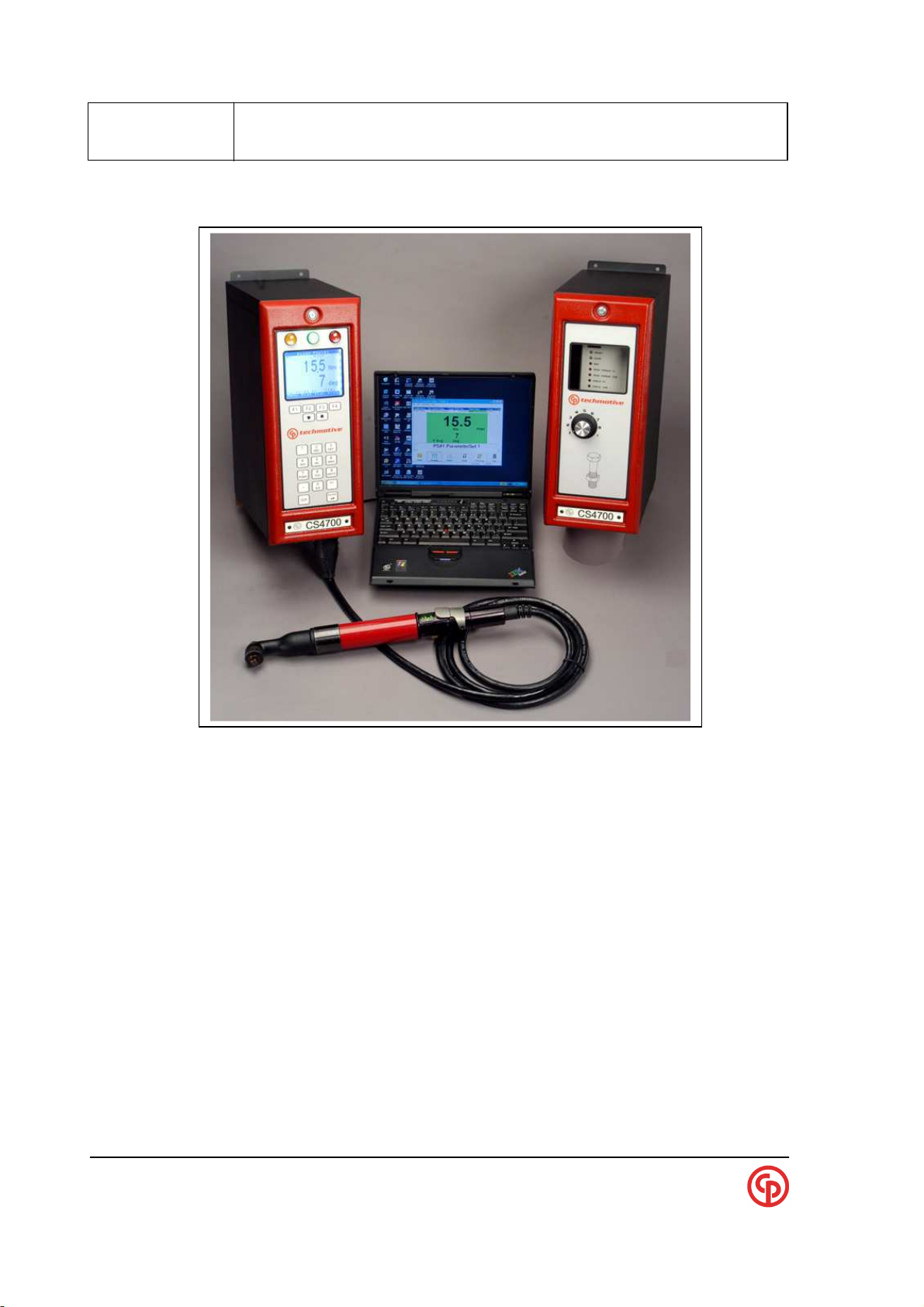
CS4700/2700 Controllers
46 and 66 Series Electric Fastening Tools
CP Techmotive
22705 Heslip Drive
Novi, Michigan 48375 USA
Technical Reference
for use with
and SD25 Electric Screwdrivers
Rev 0.7 November 30, 2005
CP P/N :
Techmotive P/N : 39-30-43083
Page 2

xxxxxxxxxx CS2700/4700 Controllers Technical Reference_________________________________________
24-Hour
Technical Support
Toll Free in the U.S. and Canada:
1-877-224-7377
All other countries:
(001) 248-348-6280
between 8 a.m. and 5 p.m.
Eastern Standard Time (EST)
NOTE: Chicago Pneumatic Tool Company (CP) in 2005
acquired and changed the name of GSE tech-motive tool
to CP Techmotive. Product Information may be found on
www.cp.com.
NOTE: The part number for the Visual Supervisor (VS) software
program is 464000-03330 (CP part number 6150040915)
NOTE: A variety of related technical manuals in .pdf format
may be downloaded from www.cp.com. Click on the
Technical Info link on the left column. Select Technical
Documentation. Scroll through the list to find the title of
the product you require, and click!
CP Techmotive manufactures products under the CP, CP Techmotive, and tech-motive tool® brand names
Information and technical diagrams in this manual are subject to change without notice. techmotive tool is a
registered trademark. Products and services referred to in this book may be either trademarks and/or registered
trademarks of their respective owners.
____________________________________________________________________________________________
Page 2 39-30-43083
Page 3

Safety:
Working with fastening tools can be dangerous if safe and proper procedures are not followed. As
with all machinery, certain hazards can be involved with the operation of the product. Using these
tools with respect and caution will considerably lessen the possibility of personal injury. If, however,
safety precautions are overlooked or ignored personal injury to the operator can result.
Always use common sense and exercise caution when using these tools. They can produce high
torque that, unless properly compensated for, could cause personal injury. Remember, your personal
safety is your responsibility.
If you are an operator or CP Techmotive qualified service technician, you should become familiar
with the contents of this manual before operating, servicing, or maintaining any part of the 4700/2700
Controller. Familiarization with all components of the system can minimize the possibility that an
accident or injury might occur.
CP Techmotive assumes no responsibility for personal injury or damage to equipment resulting from
misuse of these tools. After reviewing this manual you should also review all safety procedures
provided by your company and the equipment installer.
WARNING!
!
Failure to follow these steps can result in serious personal
injury.
General Machine Safety
• FOR YOUR OWN SAFETY READ THE INSTRUCTION MANUAL THOROUGHLY
PRIOR TO OPERATING THE TOOL.
• DO NOT WORK IN A DANGEROUS ENVIRONMENT. Do not use power tools in a damp
or wet location or explosive atmosphere, or expose them to rain, oils, or corrosive fluids.
• KNOW THE LOCATION OF POWER DISCONNECTS AND EMERGENCY STOP
BUTTONS PRIOR TO OPERATING THIS EQUIPMENT.
• KEEP ALL ELECTRICAL PANELS CLOSED DURING OPERATION. High voltage
present inside enclosure panels can result in personal injury. Do NOT bypass or defeat
electrical safety devices. Turn the power actuator to the OFF position prior to any servicing
or maintenance of the controller.
• Observe all government and/or company power lockout standards.
• NEVER OPERATE SOLENOID VALVES, LIMIT SWITCHES OR RELAYS
MANUALLY as this practice can create dangerous, unexpected machine movements.
• SECURE THE TOOL. Tools that develop torque can produce hazardous torque reactions.
Always be sure that the tool is properly fixtured to absorb reaction as a fastener is tightened.
Never operate a tool capable of high torque without proper fixturing.
• SECURE WORK. Avoid situations where the part being fastened breaks loose and can cause
damage.
• NEVER TOUCH OR ATTEMPT TO STOP MOVING MACHINERY OR PARTS WITH
YOUR HANDS, OTHER PARTS OF YOUR BODY, OR MAKESHIFT DEVICES.
Page 4

xxxxxxxxxx CS2700/4700 Controllers Technical Reference_________________________________________
• DO NOT OPERATE THE TOOL WHILE UNDER THE INFLUENCE OF
ALCOHOL, DRUGS OR MEDICATION THAT CAN IMPAIR YOUR
JUDGMENT.
• REPORT ALL UNSAFE WORKING CONDITIONS OR PRACTICES TO YOUR
SUPERVISOR AND / OR SAFETY DEPARTMENT FOR CORRECTION.
• WEAR APPROVED SAFETY GLASSES AT ALL TIMES.
• DO NOT WEAR JEWELRY, especially bracelets and rings, while operating the
fastening tools. Keep hands and fingers away from all rotating parts and avoid
situations where clothing can become tangled in the tool. Secure loose fitting
clothing, neckties, and long hair. Wear medical alert identification cautiously.
• DO NOT OVERREACH. Keep proper footing and balance at all times.
• KEEP YOUR WORK AREA CLEAN. Do not work on or near slippery floors or
surfaces. Avoid situations where the tool reacts against unexpected obstacles. Do not
operate electrical equipment while standing on a wet floor.
• MAINTAIN TOOLS IN TOP CONDITION. Keep tools properly lubricated and
clean. If any wires become frayed or exposed, replace them immediately. Prevent
dirt, grease or contaminants from getting into the tool.
• REDUCE THE RISK OF UNINTENTIONAL STARTING. Be careful how the tool
is left unattended. Avoid resting it on its throttle lever to prevent false starts.
• CONTROL THE DIRECTION OF ROTATION. The reaction torque changes
direction when going from forward to reverse. Always be aware in which direction
the tool will rotate prior to using it. If the tool is not fixtured this will allow you to
brace for the proper direction of torque reaction.
• CHECK DAMAGED PARTS. Before further use of a tool, any part of the tool that
is damaged should be carefully checked to ensure that it will operate properly and
perform its intended function. Check for alignment of moving parts, breakage of
parts, mounting, and any other conditions that may affect its operation. Never
operate a tool that has damaged or exposed wires. Never operate a tool that has any
part of the powertrain, other than the output spindle, exposed.
Electrical Safety
Only qualified and properly trained personnel should perform electrical/electronic
troubleshooting and repair. Consider the following electrical system safety
guidelines:
• Before you troubleshoot or service a fastening system station, be sure you have an
up-to-date and appropriate set of electrical drawings for that station.
• Remove metal items, such as rings, metal necklaces, wristwatches and jewelry, as
these can create electrical hazards. Wear medical alert identification cautiously.
• Wear safety glasses, but avoid wearing those that have metal rims or metal side
shields.
• It may be necessary to troubleshoot equipment while the power is ON. ONLY
qualified, trained personnel should do this. During these instances, open only the
____________________________________________________________________________________________
Page 2 39-30-43083
Page 5

_____________________________________________________
panels, doors, or covers, which need to be opened. Know the voltage present at all
points before you begin troubleshooting.
• Use properly insulated tools when working on electrical equipment to reduce the
possibility of shock. Make sure the insulation is adequate to safeguard against the
high voltages present.
• If you must work on the electrical system, be sure the main disconnect switch on the
power panel is in the OFF position and locked out with locks from each trade
involved in the repair.
• Do not attempt to modify or repair the machine without the approval of the proper
authorities.
• Uses approved fuse pullers when changing fuses.
• Never use jumper wires or fuse substitutes to replace specified fuses.
• Always use fuses of a capacity smaller than or equal to the safe capacity of the line
or the equipment it serves.
• Before you work on any circuit, check it with an appropriate testing device to be
sure voltage is not present.
• Install temporary wiring as safely as possible and replace it with permanent wiring
as soon as possible. Install grounding wherever it is needed in the final installation.
If modifications are made to the system wiring, drawings must be revised to
illustrate this change.
CS4100/2100 Controllers Technical Reference
• Know how to deal with electrical fires properly. Keep carbon dioxide and powder
extinguishers handy.
Earth Connection
Make sure that the controller is properly grounded via a protective conductor. The tool is connected to
earth by means off a ground wire internal to the cable via the controller. This protects the operator
from any electric shock.
Differential circuit breaker
The controller is fitted with a differential circuit breaker for user protection. This device detects any
insulation defect in the cable or in the tool. The tool will stop when a leakage current is 30 mA or
more; is detected by the device. The device will protect the operator from any electric shock and
protects the servo drive from deterioration of the power stages. The device can be reset manual by
resetting the trip switch to the “ON” position. See Exterior Component Section for location.
Software Features
Their are several feature build into the software to protect the operator from being injured because of
joint, servo and tool problems; Lock rotor, high limit torque shutoff, high limit angle shutdown,
temperature shutdown, tool communication failures, 120 % of the tools capacity. Any of these failures
will be displayed on the tool control module.
Locked rotor – Power being supplied to tools motor but no rotation on the output spindle
Temperature shutdown – Motor temp sensor open because of excessive heat build in motor
High Limit Shutdown – Tool shutdown because high limit torque was exceeded
High Angle Limit Shutdown – Tool shutdown because high limit angle was exceeded
Tool Communication – Cable bad, Intelligence tool interface printed circuit board failed
____________________________________________________________________________________________
September 2005 Page 3
Page 6

xxxxxxxxxx CS2700/4700 Controllers Technical Reference_________________________________________
Preface
The CS4700/2700 controllers are functionally equivalent to the CS4100/2100. In fact, most of the
internal electronics and software is identical. The CS4700/2700 packaging has been improved to be
smaller and lighter.
The CS4700/2700 Controller manufactured by CP techmotive tool is a component of one of the most
powerful DC electric nutrunner fastening control systems available. The system uses 100% digital
technology from the tool to ensure accurate and reliable fastening and data acquisition.
Microprocessors in both the fastening tool and the controller’s tool control module (TCM) enable the
system to perform to levels of accuracy while providing easy set-up and operation previously
unattainable. With Intelligent tool technology you no longer need to enter tool identification,
calibration, angle counts, speed and other information. You simply plug in the tool, power on the
system, program the desired tightening specifications and begin production.
A complete nutrunner fastening control system is made up of one of the following:
* A CS4700 Controller with a CP techmotive tool 56, 66 or 116 Series nutrunner, 27 A tool control
module (TCM) and cable
* A CS4746 Controller with a 46 Series nutrunner, 8 A TCM and cable
* A CS2700 Controller with a SD25 electric screwdriver, 6 A TCM and cable
The CP techmotive tool Visual Supervisor software program is used for system setup, fastening, data
collection, and diagnostics although basic programming can be done by a local keypad and display on
some models.
Who Should Use This Manual
This manual is written for the engineers, technicians and users who will set-up and/or operate the
CS4700/4746/2700 Controller with their respective nutrunner or screwdriver models listed above.
How to Use This Manual
This manual provides installation, maintenance and technical information about the CS4700/2700
Controllers.
This Preface provides conventions and abbreviations used throughout this manual.
It is recommended that you read this manual entirely before you use a CS47XX/2700 Controller.
This manual may have some illustrations and text that applies to the latest firmware:
CCM 1.13
DCM 6.16
VS 3.33
____________________________________________________________________________________________
Page 4 39-30-43083
Page 7

_____________________________________________________
Conventions
The following conventions are used throughout CP techmotive tool manuals for the safety of
personnel, equipment, software, and data. (Not all of these conventions are used in every manual or
guide.) The conventions include warnings, cautions and notes, as follows:
CS4100/2100 Controllers Technical Reference
WARNING!
!
CAUTION! There may be damage to equipment, and loss of software
NOTE:
?
Abbreviations
Some of the most common abbreviations used throughout this manual include the following:
AIM Anybus Interface Module (a PC board) used whenever a Field-bus option is added
API application program interface (Usually a PC based program generic interface)
CCM Communications control module (a PC board) used to add Ethernet and other options
E2PROM electrically-erasable programmable read-only memory (holds the program on the DCM,
CCM, TDM and AIM)
I/O input/output
IEEE Institute of Electrical and Electronic Engineers
EPR error-proofing ready
IP internet protocol
LED light emitting diode
PLC programmable logic controller
TCM tool control module (the central box which contains tool controller CPU & Servo)
TCP/IP transmission control protocol/internet protocol
TDM techmotive display module (a PC board)
SDLC synchronous data link control (CP techmotive tool’s RS-485 protocol)
V volts
VS Visual Supervisor - the setup, fastening, data collection, and diagnostics software
program developed by CP techmotive tool
It can be dangerous to personnel and/or machine systems,
if operating instructions are not followed. The information
appears in a box in italicized boldface type.
and data, if operating instructions are not followed. The
information is indented and in italicized boldface type.
Information that adds to your knowledge of the equipment
and/or software. The information is indented and italicized.
____________________________________________________________________________________________
September 2005 Page 5
Page 8

xxxxxxxxxx CS2700/4700 Controllers Technical Reference_________________________________________
Table of Contents
Product Dimensions, Weights and Power requirements .............................. 7
Product Compatibility Information ................................................................. 8
CS4700 Part Number Codes ............................................................................ 9
CS4700 General Information.......................................................................... 10
Location of Major Components .................................................................... 13
Keypad & Display operation .......................................................................... 14
Console/Diagnostic Port ............................................................................... 17
Printer/Barcode Port ...................................................................................... 18
Communications Methods (Ethernet/SDLC/RS232) ..................................... 20
Fieldbus .......................................................................................................... 23
Default mapping
Std (Standard mapping)
GM8/GM4
Bcin (Barcode special)
SEQ (Sequences special)
Determining INPUT sources .......................................................................... 29
DeviceNet ........................................................................................................ 31
Profibus .......................................................................................................... 33
Ethernet/IP & Modbus-TCP ............................................................................ 37
Optional CCM PC boards and Layouts ......................................................... 40
CCM+
AIM
TDM
Special Applications ...................................................................................... 44
PFCS
GM
FORD
Screwdriver and Specialty tool applications
General TROUBLESHOOTING ....................................................................... 53
CS4700 Data flow block diagram (Focus on Barcodes) .............................. 54
____________________________________________________________________________________________
Page 6 39-30-43083
Page 9
_____________________________________________________
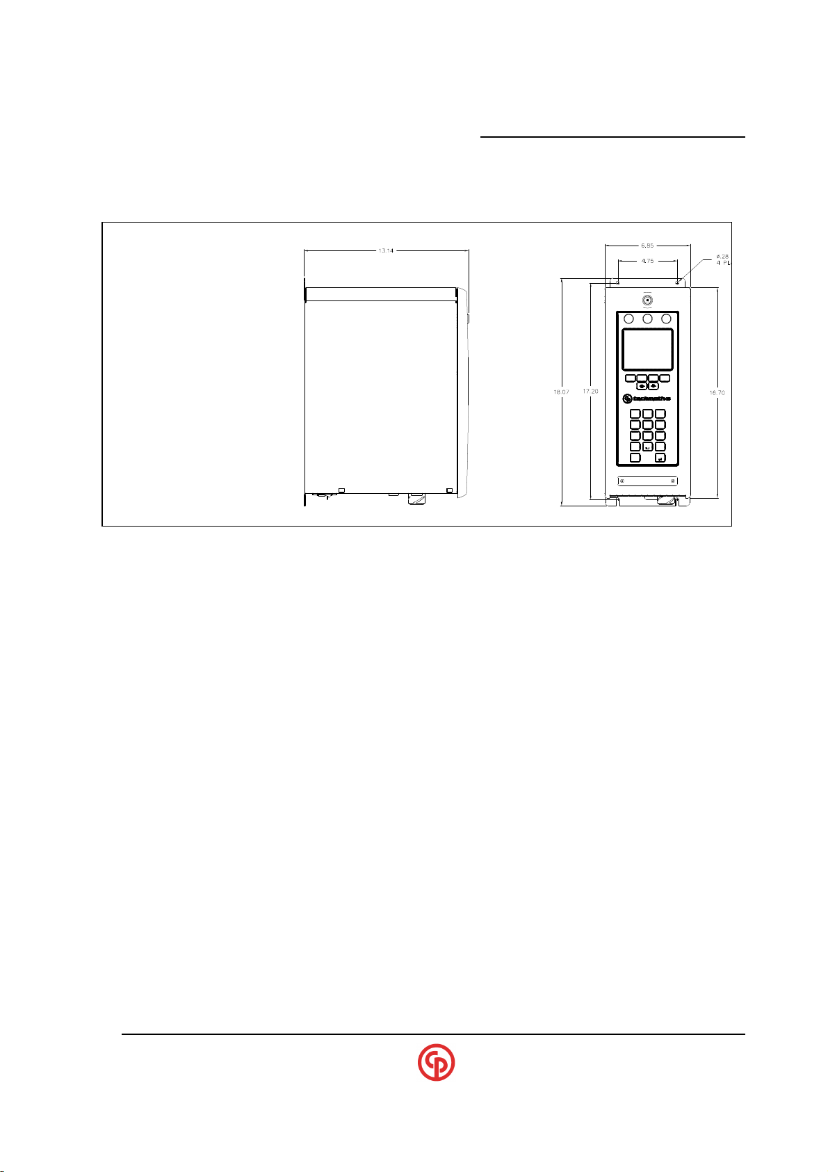
Product Dimensions and Weight
CS4100/2100 Controllers Technical Reference
F1 F2 F4F3
4
PQRS7TUV
.
CLR
ABC
21
809
3
DEF
MNO6JKL5GHI
WXYZ
+/-
ENTER
DIMENSIONS in INCHES
Weight:
Approximate Weight = 30 LBS. (Weight will vary slightly depending on configuration)
Input Voltage Requirements:
CS2700 (115v) - 115vac +15%,-10%; 50/60 Hz (.5 to .75 kva recommended)
CS2700 (230v) - 230vac +15%,-10%; 50/60 Hz (.5 to .75 kva recommended)
CS4746 - 230vac +15%, -10%; 50/60 HZ (.75 to 1 kva recommended)
CS4700 - 230vac +15%, -10%; 50/60 HZ (.75 to 1 kva recommended)
CS4746 - 115vac or 230vac +15%, -10%; 50/60 HZ (.75 to 1 kva recommended)
CS4700 - 115vac or 230vac +15%, -10%; 50/60 HZ (.75 to 1 kva recommended)
Note: Voltage levels can effect the maximum speed capability. The supply (kva) can
effect the ability of the tool to achieve rated torque especially on soft joints.
(If supplied with 230v only TCM’s)
(If supplied with 115/230v Dual voltage TCM’s)
____________________________________________________________________________________________
September 2005 Page 7
Page 10
xxxxxxxxxx CS2700/4700 Controllers Technical Reference_________________________________________
Product Compatibility Information
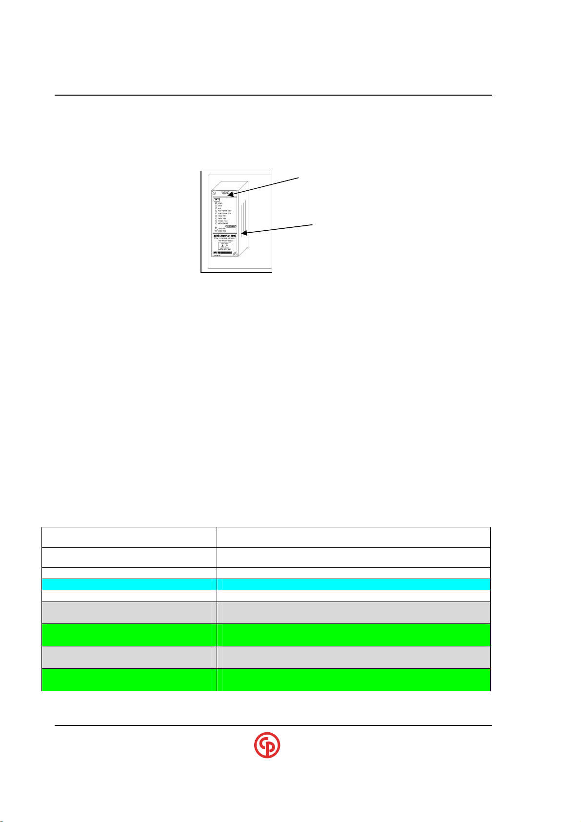
TCM compatibility
It is generally recommended that 230vac (versus 115vac) be used in most industrial
applications since periodic power loading can result in supply-line drops that could limit torque
capability on soft-joint (demanding) torque applications
The 4700 and 4746 (66 and 46 series tools) can be equipped with TCM’s which are dual
voltage capable (115v or 230vac nominal). Please consult factory if 115v (or dual voltage
capability is required). (See table below)
The TCM models (dual voltage capable) are backward compatible which means they
will work in any current or older controller. Please notice that some CS4700 models require a
revision K or higher TCM to operate properly.
Generally, plugging in an incompatible TCM will not cause any damage but will result
in the following:
1. It will work fine (but it may only run at 230vac)
2. It won’t power-up at all (If TCM older than rev. K and that model required rev. K)
230v (or) 115/230v (Dual voltage capable)
230v (or) 115v (Screwdrivers)
Revision & Part#
CONTROLLER TCM requirements
115v CS2700 (Screwdriver) 49-4100-01C2 All revisions
230v CS2700 (Screwdriver) 49-4100-01C3 Revision K or higher
CS4700 plastic-connector (230v)
(115/230v)
CS4746 plastic-connector (230v)
(115/230v)
CS4700 SMC metal conn. (230v)
(115/230v)
CS4746 SMC metal conn. (230v)
(115/230v)
____________________________________________________________________________________________
Page 8 39-30-43083
49-4100-03C5 All revisions (But 230v operation only)
49-4100-03C5D Dual Voltage capable
49-4100-01C5L All revisions (But 230v operation only)
49-4100-01C5LD Dual Voltage capable
49-4100-03C5 Rev. K or higher (But 230v operation only)
49-4100-03C5D Dual Voltage capable
49-4100-01C5L Rev. K or higher (But 230v operation only)
49-4100-01C5LD Dual Voltage capable
Page 11
_____________________________________________________
CS4100/2100 Controllers Technical Reference
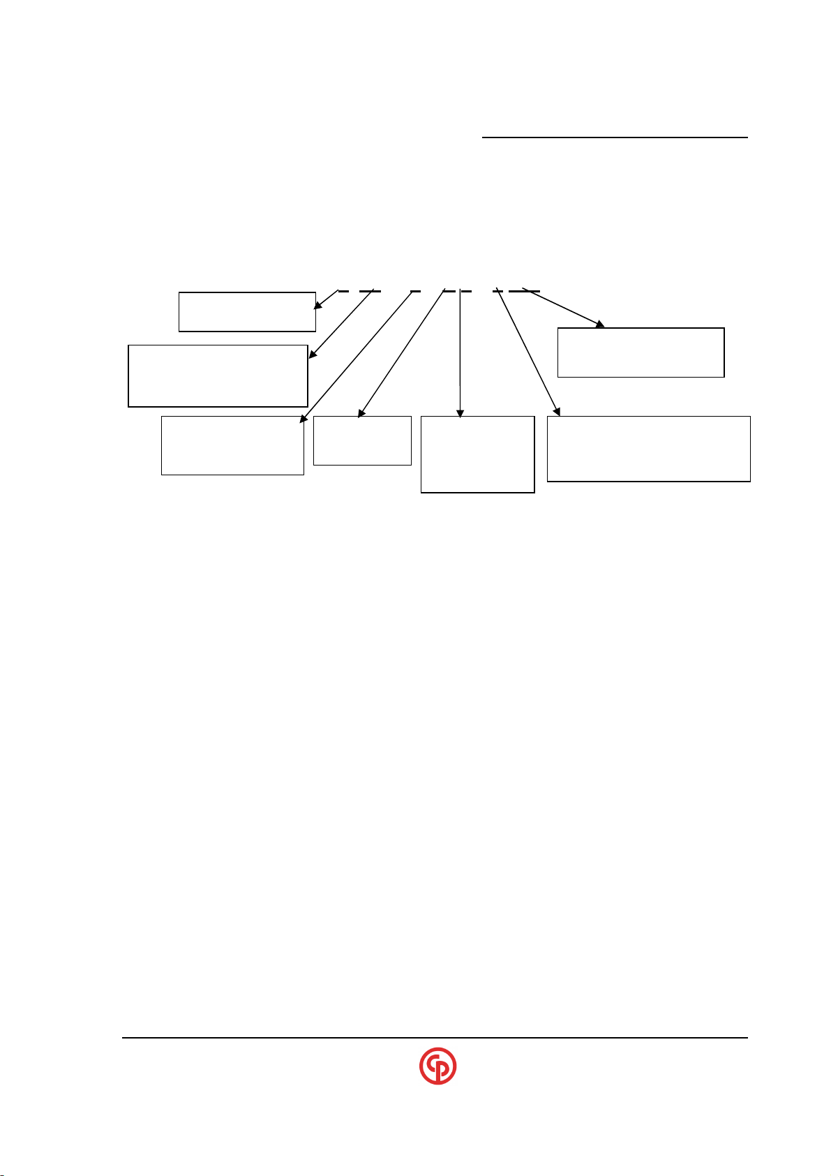
Product Part Number Codes
Product part# C4700 A 0 1 K 2 1 6 054
00 – 66/56 Series
46 – 46 Series
Notes: ** - The 4700 & 4746 models are capable of DUAL voltage (115/230v) if supplied with Dual-voltage
capable TCM’s.
2 – Screwdriver
4 – 46/56/66
(or SD25 Screwdriver)
Pset Select Switch
P – Present
0 – Not Present
K – Keypad
V – VS req’d
1 – 115V
(C2100 only)
2 – 230V **
Codes for special options
(See Below)
2 – Standard Screwdriver conn.
6 – Plastic tool connector
7 – Metal (SMC) tool connector
Special SUFFIX Codes
ASSIGNMENTS: (Subject to change)
1-PFCS (Ethernet) 6-Interbus-S
2-Reserved 7-Modbus-Plus
3-Reserved 8-Profibus-DP/DPV1
4-DeviceNet 9-Reserved
5-Ethernet (10 Base-T) A-Ethernet-IP /Modbus TCP
B- PFCS (RS232 Terminal Server)
Other Letters: Future use
NOTE:
?
When Ethernet is present, DaimlerChrysler PFCS Ethernet is
always available. Likewise GM and Ford interfaces are
available on Ethernet-capable units.
____________________________________________________________________________________________
September 2005 Page 9
Page 12
xxxxxxxxxx CS2700/4700 Controllers Technical Reference_________________________________________
these input sources.
CS4700 General Information
Units with Keypad/Display
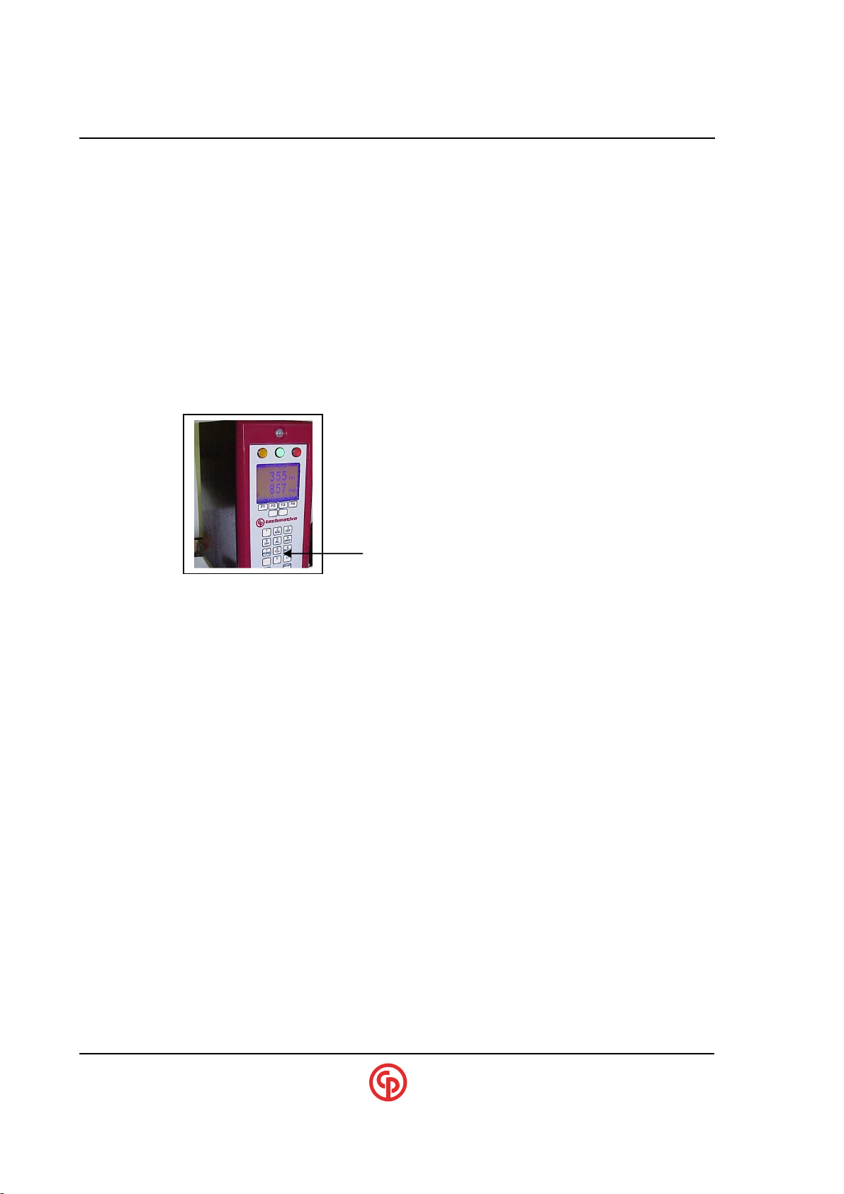
If the controller has a Keypad/Display, you may simply connect the tool, go into the Menu and select
Defaults (pick TOOL I/O). This provides a quick way to get up and running immediately. On these
units, you may prefer to use the Visual Supervisor (VS) program initially for even easier setup
especially if the process is complex.
NOTE:
?
When setting up these defaults it is also possible to select the
source of the TOOL commands (fieldbus or the tool switches)
and the source of the parameter selections (fieldbus, physical
I/O or the keypad menu). If you require I/O mapping that is not
among the default selections, VS will be required to customize
Use +/- key on RUN screen to adjust contrast
Use Decimal-pt. on RUN screen to REVERSE blue/white
Units without Keypad/Display
Controllers without the Keypad/Display must be configured using the VS software. If the unit is
Ethernet capable, some of the configuration (like setting up IP addresses, etc.) must be done via the
RS-232 console port. The default selections can also be done via the RS-232 console if necessary.
VS should be used to fine-tune selections/parameters.
Units with Ethernet/Fieldbus Capability
Many models are supplied with Ethernet capability. This Ethernet link can go to CP techmotive tool’s
VS-embedded system software or to an API interface or to a number of selectable custom software
interfaces for Ford, GM and DaimlerChrysler. The controller can also be upgraded with one of a
number of standard fieldbus interfaces. These will enable interfacing to PLCs via a standard bus to
provide data and I/O exchange.
All Units with CCM’s
A Communications Control Module (CCM) is added whenever Ethernet, a keypad/display or a
fieldbus is required. Whenever the CS4700 has a CCM, you may need to connect to the CCM via the
DIAGNOSTICS RS-232 port on the bottom panel of the controller. By running HyperterminalCONSOLE (at 9,600 baud), a text-based dialog will allow you to set the TCP/IP address and other
parameters as well as to perform extended diagnostics. Examples of this dialog are found later in this
document. Remember: when making critical changes be sure to initiate the “COMMIT” command to
store all of the requested changes permanently into E2PROM. Note that newer revisions of software
permit editing of various Ethernet parameters via the keypad/display.
____________________________________________________________________________________________
Page 10 39-30-43083
Page 13
_____________________________________________________
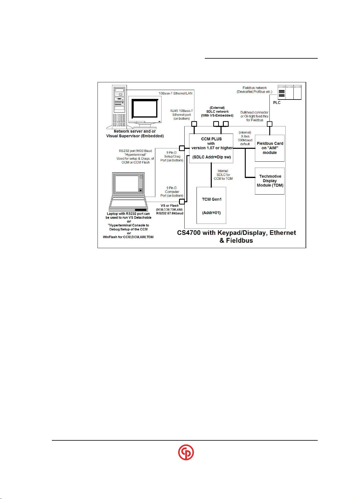
CCM+ Based Block Diagram
CS4100/2100 Controllers Technical Reference
FIELD Upgrade Considerations
CS4700/4746/2700 Controllers are considered BASIC models if they have only a TCM. Adding a
CCM makes the unit “Ethernet capable.” With the CCM in place, it is possible to add the Fieldbus
capability and/or the Keypad/Display option. Keep in mind that E2PROMs exist on the TCM, CCM,
Anybus Interface Module (AIM) and techmotive device module (TDM), which may be updated
periodically. Beginning with CCM version 1.07 and with “WinFlash 1.12 or higher, it is possible to
flash upgrade the TDM, AIM or even the TCM via the CCM Flash port connection.
____________________________________________________________________________________________
September 2005 Page 11
Page 14
xxxxxxxxxx CS2700/4700 Controllers Technical Reference_________________________________________
Units with CCM+ (Ethernet capable)
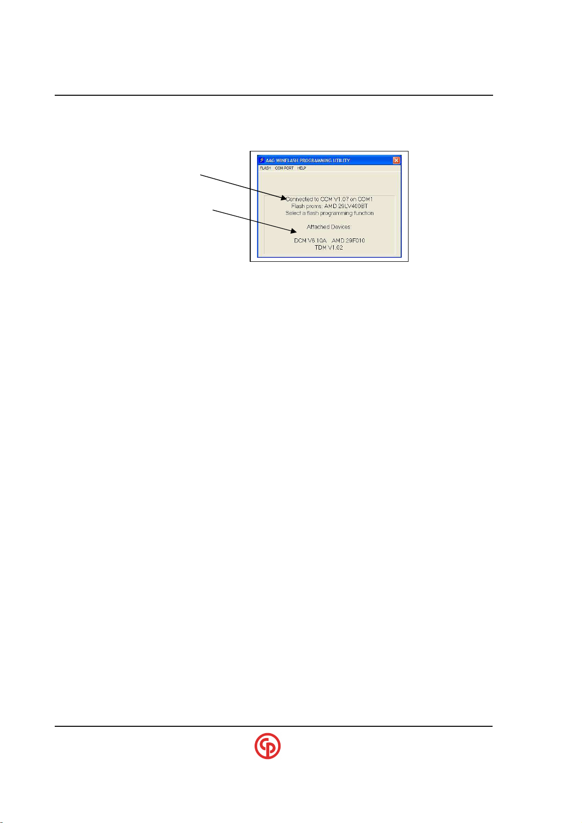
All Flash updates can be done simply from the CS4700 Controller RS-232 computer port without
going inside the box or moving any cables (as required of the original CCM units).
CP Techmotive Winflash
Utility - the primary
connection to the CCM
Downstream devices
and software revisions
NOTE:
?
WinFlash is CP techmotive tool’s software update utility
applicable to the CCM, CCM+, or direct TCM connection.
Save/Restore with VS3.33 & CCM1.11 (or higher rev.)
setup. Previous versions of software would not save the settings associated with the CCM and
Fieldbus entities. Within VS files such as .vsc and .dev can save the CS4700 configuration and
restore it. These files contain this additional information as extended data. If trying to restore a
CS4700 from a file and it didn’t have the hardware for this extended data, the CCM will still
restore but it will just throw away the extended setup data that it cannot use.
Upgrading to VS3.33 and CCM1.11 provides the ability to save and restore the complete CS4700
____________________________________________________________________________________________
Page 12 39-30-43083
Page 15
_____________________________________________________
CS4100/2100 Controllers Technical Reference
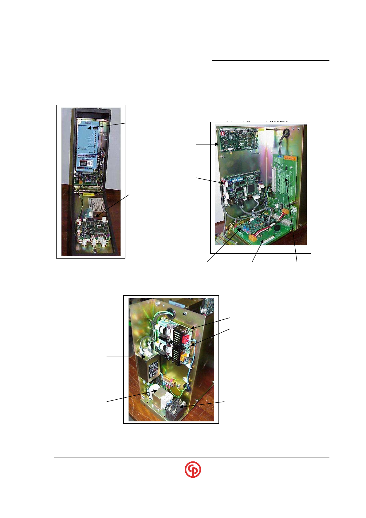
Location of Major Components
CS2700 with Door open
TCM Internal Frame of CS2700
AIM
(Fieldbus Module)
CCM
(Communications
TDM Module )
(Display Module)
Internal ITI board Bottom Connector bd Backplane
(CS2700 only)
24vdc power supplies
Digital I/O power
CCM & add-on option power
Line Filter
GFCI Circuit Breaker / On-Off switch
____________________________________________________________________________________________
September 2005 Page 13
Page 16
xxxxxxxxxx CS2700/4700 Controllers Technical Reference_________________________________________
Keypad/Display Operation
Entering SETPOINTS Via the Keypad
The detachable version of VS (VS loaded onto a laptop PC that is connected to the controller) can be
used as an enhanced local programming facility, as not all setpoint functions are available via the
keypad. Connecting detachable VS will ‘disable’ the ability to change setpoints via the controller
keypad until the computer running detachable VS is disconnected.
VS Embedded Connections
Embedded VS (available when a controller has a built-in industrial computer and monitor) can be
used via the Ethernet port or SDLC (RS-485 port).
NOTE:
?
SECURITY: Visual Supervisor and the Keypad
The CS4700 with Keypad/Display can be set up with passwords and multiple access levels. Security
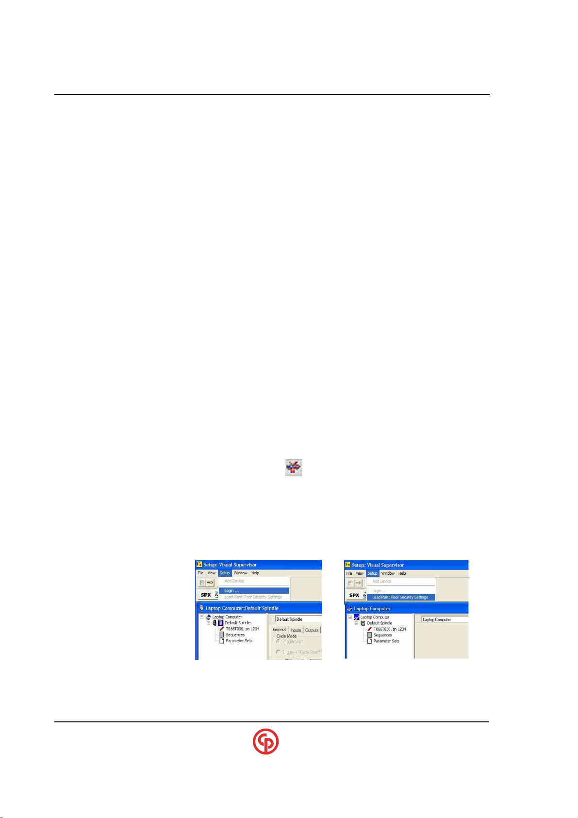
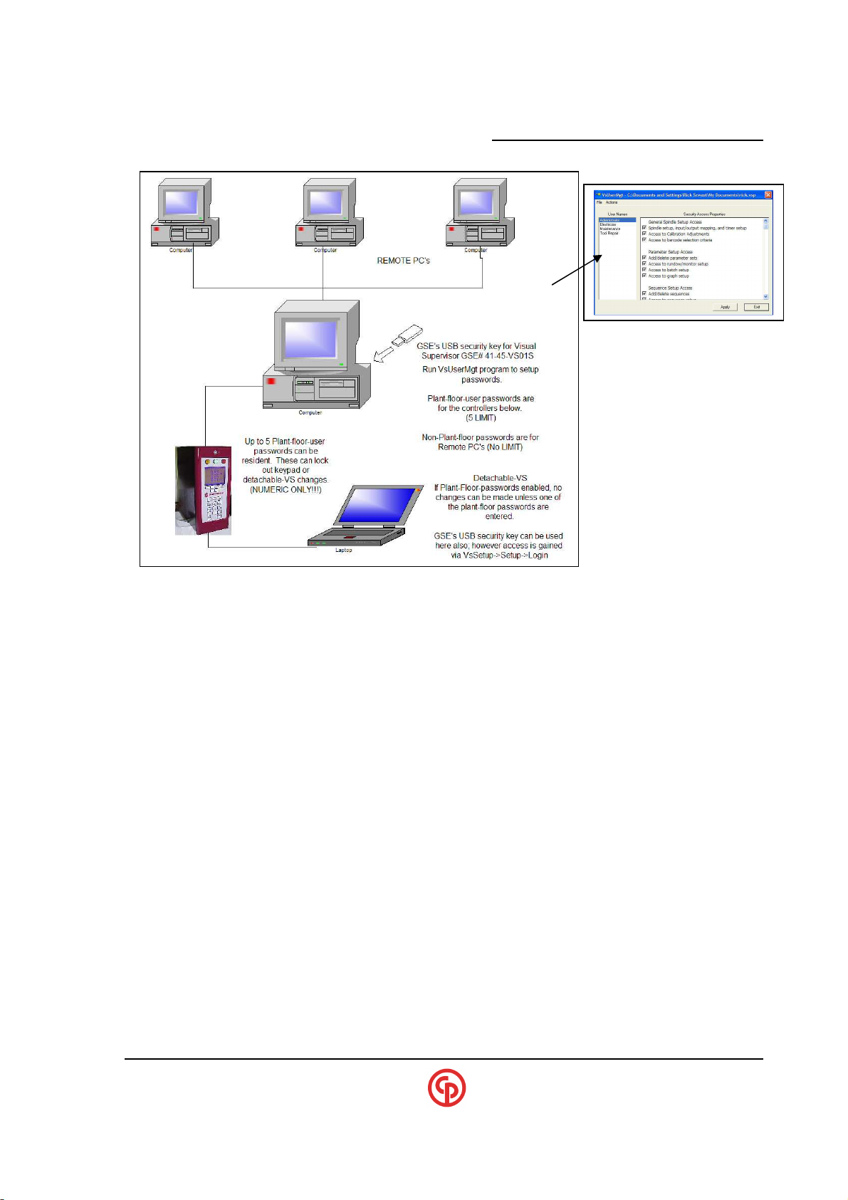
is set up using the VS program VsUserMgt (VS3.28 or higher is required). VS allows an almost
infinite number of users with individual levels of security to use the system. However, only five
special passwords can be sent to the controller for security at the keypad and VS-Detachable level.
These special passwords are called “Plant Floor Security Passwords, and they must be numeric. You
must use the VsUserMgt utility and a USB key to set these up.
If the unit is Ethernet-capable, SDLC (RS-485) is available only
on CCM+ based units. Changes made by the controller keypad
or detachable VS will be immediately reflected on the
embedded VS screen. The VS Embedded PC can also be used
to change the settings. In these environments, it may be
desirable to implement security (refer to the next paragraph).
NOTE:
?
____________________________________________________________________________________________
Page 14 39-30-43083
The “embedded” version of VS will load the Plant Floor Security
passwords into the CS4700 Controller when VsMain starts.
Make sure the VS Icon is removed from the tool tray and restart VsStart to have the Plant Floor Security settings transferred.
The “detachable” version of VS can also load the CS4700 with the
passwords, but the mechanism is different. You must enter into
VsSetup and click “setup,” and then select “Load Plant Floor
SecuritySettngs.” The lock icon indicates that the Plant Floor
Security Password is resident in the controller.
Page 17
_____________________________________________________
CS4100/2100 Controllers Technical Reference
LIMITATIONS of the Keypad
The optional Keypad/Display provides continuous information about torque, angle, parameter sets
(psets) and cycle counts. It also allows you to select psets and change many setpoints from the
keypad. Special programming configurations and many of the less frequently used parameters are not
available via the keypad, so if these must be changed then VS must be connected to the controller.
Additionally, some very application-specific functions (and TCP/IP setup) must be done via Hyperterminal on the RS-232 setup/diagnostics port.
STATISTICS – Available on Controller with Keypad/Display
A statistics function has been provided to show torque and angle statistics based on a selected sample
size. The top of the screen shows the active parameter set and the number of samples that have been
collected in the current sample “data group.” The rest of the screen shows the statistics from the
previously completed data group.
HISTORY – Available on Controller with Keypad/Display
In the history mode, the user can view the results of the last 10 cycles. Note that the TCM maintains a
much larger history buffer which can be extracted via Visual Supervisor software. Also note that the
size of the TCM history depends on the History mode setting.
____________________________________________________________________________________________
September 2005 Page 15
Page 18
xxxxxxxxxx CS2700/4700 Controllers Technical Reference_________________________________________
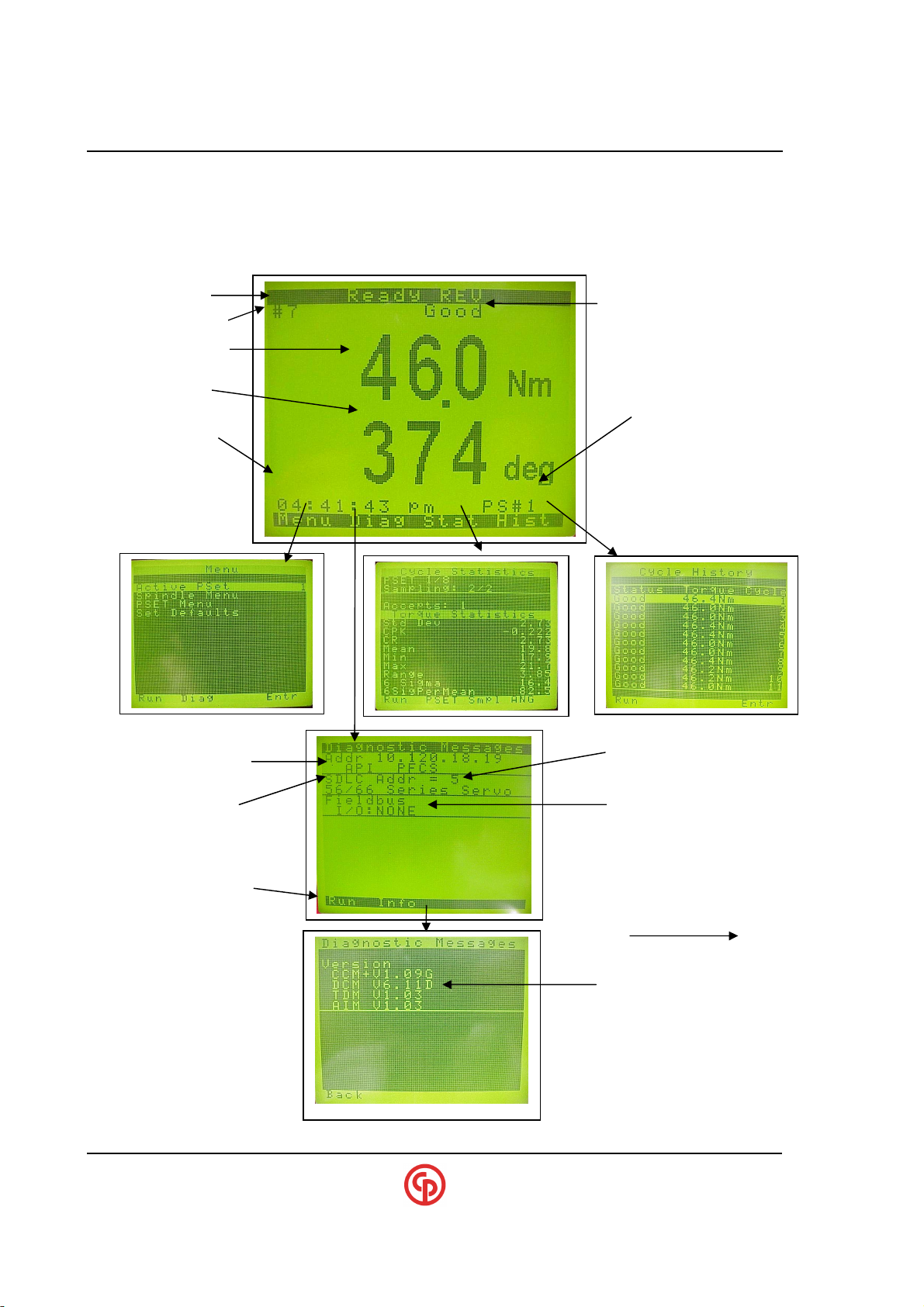
Last Cycle
Final Angle
CS4700 TCP/IP address
tech-motive
Display
Applicable Ethernet
VS is set up to talk via
Fieldbus and
All software resident
Keypad Display Characteristics
If a setpoint falls outside of the tool’s capability or internally contradicts the operation of the tool, the
setpoint change will be rejected. You may still need to connect the VS program to address some setup
issues.
Current Status
Last Cycle Count#
Peak/Final Torque
(if applicable)
Time of Last Cycle
Connection programs
armed (shows API, PFCS.
VS and others possible)
Module & S/W Verson
Last Cycle Declaration
Parameter Set #
RS-485 (address #5
miscellaneous information
within the
CS4700/4746/2700
Controller
____________________________________________________________________________________________
Page 16 39-30-43083
Page 19
_____________________________________________________
CS4100/2100 Controllers Technical Reference
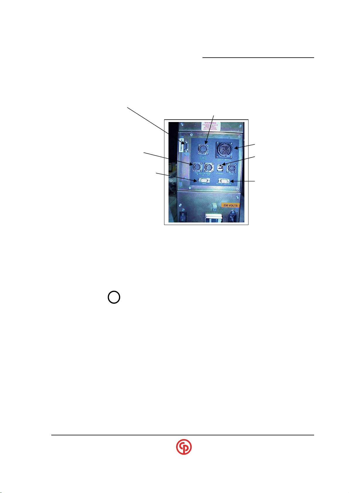
Comm/Diag
(Comm. RS232 Setup & Diagnostics )
A null-modem cable that provides an RS-232 connection (typically 9 pin-d female on both ends) is
required for setup of the CCM module. This cable plugs into the CS4700 Mini Controller
Comm/Diag port.
Digital I/O connector
Tool Connector
SDLC Network (RS485)
(In and Out Connectors) Ethernet connection
VS (RS-232) DETACHABLE (RS232)
(and Flash upgrade port for CCM+) Printer output
(Barcode input)
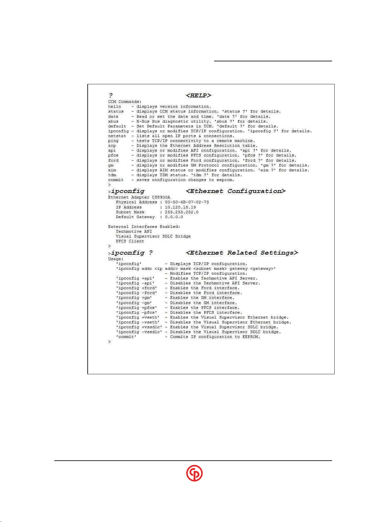
For the Debug/Setup port, use 9600 baud, 8 data, no parity and one stop bit. (Typically COM1 will be
used for the RS-232 serial connection.) When you press the ENTER key, a “>” should appear. Press
“?” to display a list of available commands. (In the captured text on the next page, the user entered the
“larger-bold” text, and the rest was the response from the CCM.) Future CCM revisions may may add
or modify the commands.
CAUTION! DO NOT TURN OFF POWER to the CS4700 controller while
making setup changes on the Console (Debug/Setup) port, as
the setting changes may be lost. You must issue one of the
“COMMIT” commands to enact/save most of configuration
settings. Any of the “COMMIT” commands will preserve all of
the setting change categories.
____________________________________________________________________________________________
September 2005 Page 17
Page 20

xxxxxxxxxx CS2700/4700 Controllers Technical Reference_________________________________________
Printer/Barcode
PRINTER PORT Characteristics: OUTPUT ONLY 9600 baud (8 data, no parity, 1 stop bit).
Data stream is sent without handshaking following each cycle.
----------------SAMPLE PRINTER OUTPUT FORMAT (TCM backplane DIP Sw # 8 OFF)----------#0110 Sp:01-01 H 15.1 Nm L 3 Deg
#0110 Cycle count (5 bytes)
Space (1 byte)
Sp: Spindle header (3 bytes)
01 Spindle number (2 bytes)
- Dash (1 byte)
01 Parameter number (2 bytes)
Space (1 byte)
H Torque Pass/Fail* (1 byte)
XX15.1 Peak torque (6 bytes)
Space (1 byte)
NmXXX Torque Units (6 bytes)
Spaces (1 bytes)
L Angle Pass/Fail (1 byte)
XXXXX3 Angle result (6 bytes)
Space (1 byte)
Deg Angle Units (3 bytes)
Carriage return (1 byte)
Line feed (1 byte)
------------------SAMPLE PRINTER OUTPUT FORMAT (TCM backplane DIP Sw # 8 ON)---------#0095 Sp:01-01PP 13.0 4.0 10.1P 9999 40 36
#0095 Cycle count (5 bytes)
Spindle name* (5 bytes)
Sp: Spindle header (3 bytes)
01 Spindle number (2 bytes)
- Dash (1 byte)
01 Parameter number (2 bytes)
P Overall Pass/Fail (1 byte)
P Torque Pass/Fail (1 byte)
X13.0 High Limit (5 bytes)
XX4.0 Low Limit (5 bytes)
X10.1 Torque Peak (5 bytes)
P Angle Pass/Fail (1 byte)
X9999 Angle High Limit (5 bytes)
XXX40 Angle Low Limit (5 bytes)
XXX36 Angle Result (5 bytes)
Carriage return (1 byte)
Line feed (1 byte)
*If Spindle Name > 6 then the Spindle name field will increase to that length (up to 32 characters).
(RS232 Printer output & barcode input)
____________________________________________________________________________________________
Page 18 39-30-43083
Page 21

_____________________________________________________
BARCODE PORT Characteristics: INPUT ONLY 9600 baud (8 data, no parity, 1 stop bit).
Note that this RS232 INPUT port will watch for specially formatted input strings for the purpose of AutoCal. from an instrument such as the M290 Torque Audit device.
Refer to Visual Supervisor Manual for Barcode setup and capability details. Some of the selectable
modes and options are as follows:
1. Attaching an identifier (Part ID, Model# or both) to each cycle
2. Forcing a barcode read before allowing the tool to run
3. Using a barcode to select a parameter set
4. Discriminate barcodes with Masking and Min/Max Length options
5. Use a barcode to attach to data continuously or one-barcode per cycle
6. Assignable I/O for clearing, bypassing and monitoring the barcode statuses
Note: In addition to this RS232 port, barcodes can also enter into the TCM for marrying to cycle data
via Fieldbus and from VS (PC software).
CS4100/2100 Controllers Technical Reference
Date, Time and Time Zone Settings
When the controller is connected to a PC running Visual-Supervisor, the controller will synchronize to the
computer’s date, time and Time-zone settings automatically.
If the controller is setup up totally independent of Visual-Supervisor (Like the unit with Keypad/Display) the user
should either link to Visual-Supervisor momentarily (to synchronize to the local time settings of the PC) or go into
the console settings and set the Date, Time and Time-zone settings. These settings can be found under the
“DATE” section of the console.
____________________________________________________________________________________________
September 2005 Page 19
Page 22
xxxxxxxxxx CS2700/4700 Controllers Technical Reference_________________________________________
CS2700
TCM backplane DIP switches set SDLC address
Connecting to Visual Supervisor (Ethernet)
.
Setting Up and Configuring the Single-Channel Controller
1. Determine the TCP/IP address information that will be designated for CS47XX/2700 Controller.
2. On the console session above, use the “ipconfig” command to enter in this information.
Typically; the mask may be something like 255.255.255.0; the Gateway 0.0.0.0
Keypad/Display units allow entering in this information via the keypad.
3. Verify that the VS bridge is enabled. The command “ipconfig +vseth” might be needed if not.
4. Be sure to use the “commit” command to save the settings permanently if using the console.
Linking VS to the Single-Channel Controller on Ethernet
1. At the VS Host Computer run VsSystemSettings.
2. Set up the controller as an Ethernet connection and enter in the IP address (from above)
VS should now link to this controller. Some computer software FIREWALLS may
try to block this connection depending on how they are configured.
3. If you have problems, use the PING command to debug, and observe the CCM’s LED’s.)
NOTE
:
?
Once a CCM has linked to a VS-embedded host on
Ethernet, the CCM will ignore any other attempted VS
connections (other than IP addresses) over the Ethernet.
Powering the controller down and then up is required to
clear the CCM of the expected IP address for its VS host
connection.
Connecting to Visual Supervisor (SDLC – RS-485)
Use the console command “ipconfig +vssdlc” to enable VS on SDLC (RS-485).
UNITS WITHOUT CCM+
CS4700/4746 TCM backplane DIP switches set SDLC address
UNITS WITH CCM+
CS2700 NOT SDLC capable
CS4700/4746 CCM+ Dip switches set SDLC address
Connecting to Visual Supervisor (RS-232)
The RS-232 “computer port” on the bottom of the CS4700 Controller provides an RS-232 (laptop PC
“Detachable VS”) connection. Typically the baud rate is set for 57.6 kbaud, provided that TCM
backplane DIP switch #7 is on; otherwise, the baud rate is 9,600 baud. On units with the CCM+, the
baud rate will be 57.6 kbaud regardless of the TCM backplane DIP switch.
____________________________________________________________________________________________
Page 20 39-30-43083
Page 23
_____________________________________________________
Sample Console Session
CS4100/2100 Controllers Technical Reference
____________________________________________________________________________________________
September 2005 Page 21
Page 24
xxxxxxxxxx CS2700/4700 Controllers Technical Reference_________________________________________
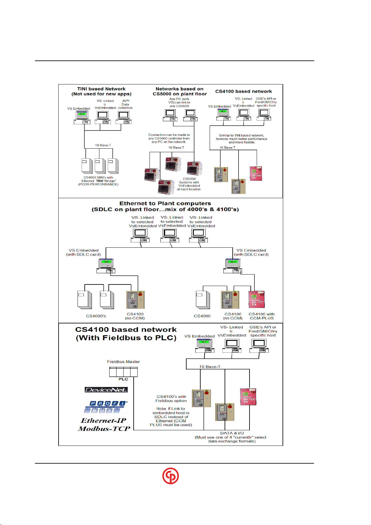
Examples of Network Topologies
(CS4100 = CS4700)
____________________________________________________________________________________________
Page 22 39-30-43083
Page 25
_____________________________________________________
CS4100/2100 Controllers Technical Reference
Fieldbus Capabilities
The CS4700 Contoller can interface to one field bus: DeviceNet, Profibus, Ethernet-IP and others are
available in order to exchange I/O and data with PLCs and other devices.
Only certain hard-coded data mapping configurations are available over fieldbus. Presently, enabling
the fieldbus I/O and selecting the data type can be done via the Console/Debug port. And some
functions can be enabled (by default) via the Keypad/Display if the controller is so equipped.
Most of the specific setup for the fieldbus is done via the console “AIM” category.
Under this category there is a “BYTE-ORDER” setting also known as “Little Endian and Big
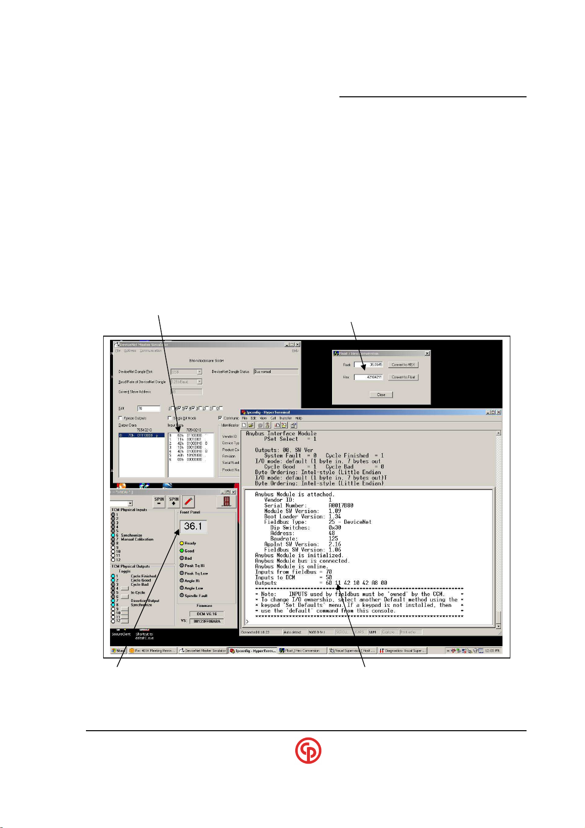
Endian”. This is done as some PLC’s and computers expect the high byte/low byte to be sent in
different order. This setting will effect the 4- byte FLOAT values as well as the 2-byte INTEGER
values. The sample below shows an example of a system running “Little Endian” which is the
DEFAULT mode.
Sample DeviceNet Host program
Showing CS4700 output bytes (Default data config.) “42104211” converted to FLOAT = 36.0645 (Ntm)
(See next page…)
CS4700 shows torque = 36.1 (Ntm) CS4700 Console (Comm/Diag) AIM Diagnostics
1st byte=Output bits, 2nd-5th bytes=Torque, 6th&7th byte=Angle
“60” “11 42 10 42” “A8 00”
____________________________________________________________________________________________
September 2005 Page 23
Page 26
xxxxxxxxxx CS2700/4700 Controllers Technical Reference_________________________________________
Byte Bit Description
2
Parameter Set Selected Bit 2
1-4 0-7 Peak Torque (IEEE Floating Point)
Byte Bit Description
5
Cycle On
FieldBus Data Mapping Types:
Default - …………..Small General purpose data mapping
Std (Standard) –…. Expanded output data and setpoints
GM8 & GM4 - …….. Special purpose for specific customer
Bcin (Barcode in) – Expanded I/O with 2 barcode inputs
SEQ (Sequences) – Expanded I/O with Full Sequence bits
TYPE: Default:
Outputs
0 0 Parameter Set Selected Bit 0
1 Parameter Set Selected Bit 1
3 Parameter Set Selected Bit 3
4 System Fault
5 Cycle Finished
6 Cycle Good
7 Cycle Bad
5-6 0-7 Final Angle (16 bit integer, 0 to 65535)
Inputs
0 0 Parameter/Sequence Select Bit 0
1 Parameter/Sequence Select Bit 1
2 Parameter/Sequence Select Bit 2
3 Parameter Set Select Bit 3
4 Cycle Enable
6 Forward
7 Clear Outputs
____________________________________________________________________________________________
Page 24 39-30-43083
Page 27
_____________________________________________________
Byte Bit Description
Byte Bit Description
TYPE: Std (standard)
Outputs
0 0 Parameter Set Selected Bit 0
1 Parameter Set Selected Bit 1
2 Parameter Set Selected Bit 2
3 Parameter Set Selected Bit 3
4 System Fault
5 Cycle Finished
6 Cycle Good
7 Cycle Bad
1-4 0-7 Peak Torque (IEEE Floating Point)
5-6 0-7 Final Angle (16 bit integer, 0 to 65535)
7-10 0-7 Torque HighLimit (IEEE Floating Point)
11-14 0-7 Torque Target (IEEE Floating Point)
15-18 0-7 Torque LowLimit (IEEE Floating Point)
19-22 0-7 Torque Fastening Threshold (IEEE Floating Point)
23-26 0-7 Torque Control Reference (IEEE Floating Point)
27-28 0-7 Angle HighLimit (16 bit integer, 0 to 65535)
29-30 0-7 Angle Target (16 bit integer, 0 to 65535)
31-32 0-7 Angle LowLimit(16 bit integer, 0 to 65535)
33-34 0-7 Speed Rundown (16 bit integer, 0 to 65535)
35-36 0-7 Speed Downshift (16 bit integer, 0 to 65535)
37-40 0-7 Tool Serial Number (Hex value) * see Note 1
41-47 0-7 VIN# (7 characters) * see Note 2
CS4100/2100 Controllers Technical Reference
NOTE 1:
Most CP techmotive tool serial numbers are 4 characters (1234),
however, some are represented in 8 characters (2C03 1234) which
?
NOTE 2:
?
includes year and month information.
History Mode (in VsSystemSettings ) must be set to a setting other
than “Standard”:
If a VIN is received that is greater than 20 characters, and
“Reduced Rundown with PartId-Barcode” is configured, the lower
7 characters of the right-most 20 will be selected.
If “Reduced Rundown with Model # Barcode” is configured, the
lower 7 characters of the left-most 20 will be selected.
If History mode is set to Standard, the VIN# will NOT be sent over
fieldbus.
If History mode is set to Standard with Both barcodes the
MODEL# barcode will be sent.
Inputs
0 0 Parameter/Sequence Select Bit 0
1 Parameter/Sequence Select Bit 1
2 Parameter/Sequence Select Bit 2
3 Parameter Set Select Bit 3
4 Cycle Enable
5 Cycle On
6 Forward
7 Clear Outputs
____________________________________________________________________________________________
September 2005 Page 25
Page 28
xxxxxxxxxx CS2700/4700 Controllers Technical Reference_________________________________________
Byte Bit Description
3 0-7 Unused
Byte Bit Description
1
Stack Light Yellow
2
Stack Light Red
7
unused
2 0-7 Unused
TYPE: GM8/GM4
Outputs
0 0 Bypass
1 Release 1 Job
2 Unused
3 Unused
4 Parameter Set Selected Bit 0
5 Parameter Set Selected Bit 1
6 Parameter Set Selected Bit 2
7 Global Accept
1 0 InCycle
1 Unused
2 System Fault
3 Cycle Finished
4 EPR
5-7 Unused
2 0 Good
1 GM Red
2 GM Yellow
3-7 Unused
Inputs
NOTE:
?
The difference between GM4 & GM8 is that GM8 mode adds
the PVI on the inputs
0 0 Stack Light Green
3 Stack Light Alarm
4 Parameter Set Select Bit 0
5 Parameter Set Select Bit 1
6 Parameter Set Select Bit 2
1 0 Cycle On
1 Reverse
2 EPR
3 Stop/Disable
4-7 Unused
3 0-7 Unused
4-7 0-7 PVI *GM8 mode only
For any INPUTS entering the controller via fieldbus, make sure that these functions are not mapped to
physical inputs into the controller (via VS). Currently, if the CCM recognizes a fieldbus connection
with “inputs” it will not allow inputs via OPC.
____________________________________________________________________________________________
Page 26 39-30-43083
Page 29
_____________________________________________________
Byte Bit Description
7
Output#4 (Mappable via VS)
Byte Bit Description
4
Cycle Enab
le
2
Batch/Sequence Abort
3-7
Spare
TYPE: Bcin (Barcode input)
CS4100/2100 Controllers Technical Reference
NOTE:
?
This option is 1st available in CCM version 1.10.
Outputs
0 0 Parameter Set Selected Bit 0
1 Parameter Set Selected Bit 1
2 Parameter Set Selected Bit 2
3 Parameter Set Selected Bit 3
4 System Fault
5 Cycle Finished
6 Cycle GOOD
7 Cycle BAD
1 0 Ready
1 Bypassed
2 Sequence GOOD
3 Sequence BAD
4 Part-ID barcode received ok
5 Model# barcode received ok
6 Spare
2-5 Peak Torque (IEEE Floating Point)
6-7 Final Angle (16 bit integer, 0 to 65535)
Inputs
0 0 Parameter Set Selected Bit 0
1 Parameter Set Selected Bit 1
2 Parameter Set Selected Bit 2
3 Parameter Set Selected Bit 3
5 Cycle On
6 Forward
7 Clear Outputs
1 0 Clear Barcode
1 Clear Barcode Requirement
2-21 MODEL# Barcode (20 Characters)
22-41 PART-ID Barcode (20 Characters)
____________________________________________________________________________________________
September 2005 Page 27
Page 30
xxxxxxxxxx CS2700/4700 Controllers Technical Reference_________________________________________
Byte Bit Description
0
1
2
7
Yield Fault Detected
3
4-7
8-9
10-13
14-17
18-21
0-7 Torque Low Limit
22-23
24-25
26-27
28-31
Byte Bit Description
0
4 Cycle Enable
1
1 Reject Lockout Clear
2 Batch/Sequence Abort
2-5
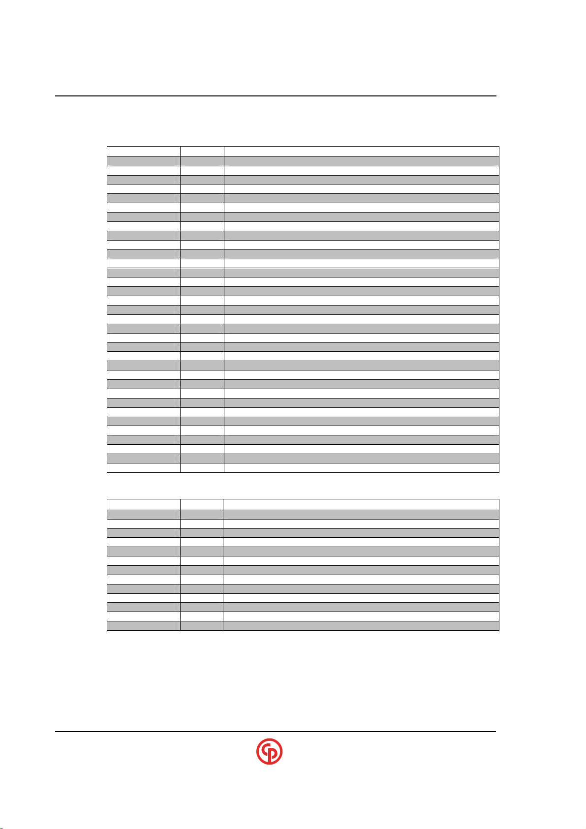
TYPE: SEQ (Sequence Support)
Outputs
0 Sequence Set Selected Bit 0
1 Sequence Set Selected Bit 1
2 Sequence Set Selected Bit 2
3 Sequence Set Selected Bit 3 (Gen2 only…..otherwise zero)
4 System Fault
5 Cycle Finished
6 Cycle GOOD
7 Cycle BAD
0 Ready
1 Sequence Finished
2 Sequence GOOD
3 Sequence BAD
4 Sequence Declared (In process)
5 Batch Finished
6 Batch Good
7 Batch Bad
0 Parameter Set Selected Bit 0
1 Parameter Set Selected Bit 1
2 Parameter Set Selected Bit 2
3 Parameter Set Selected Bit 3
4 Parameter Set Selected Bit 4
5 Bypassed
6 Spare
0-7 Spare
0-7 Peak Torque Result
0-7 Final Angle Result
0-7 Torque High Limit
0-7 Torque Target Limit
0-7 Angle High Limit
0-7 Angle Target Limit
0-7 Angle Low Limit
0-7 Spare
Inputs
0 Parameter/Sequence Select Bit 0
1 Parameter/Sequence Select Bit 1
2 Parameter/Sequence Select Bit 2
3 Parameter/Sequence(Gen2 only) Select Bit 3
5 Cycle On
6 Forward
7 Clear Outputs
0 Parameter Select bit 4 (When using psets 17-32)
3-7 Spare
0-7 Spare
____________________________________________________________________________________________
Page 28 39-30-43083
Page 31
_____________________________________________________
DEFAULT#
Parameter Set select
Tool Running control
1
2
3
4
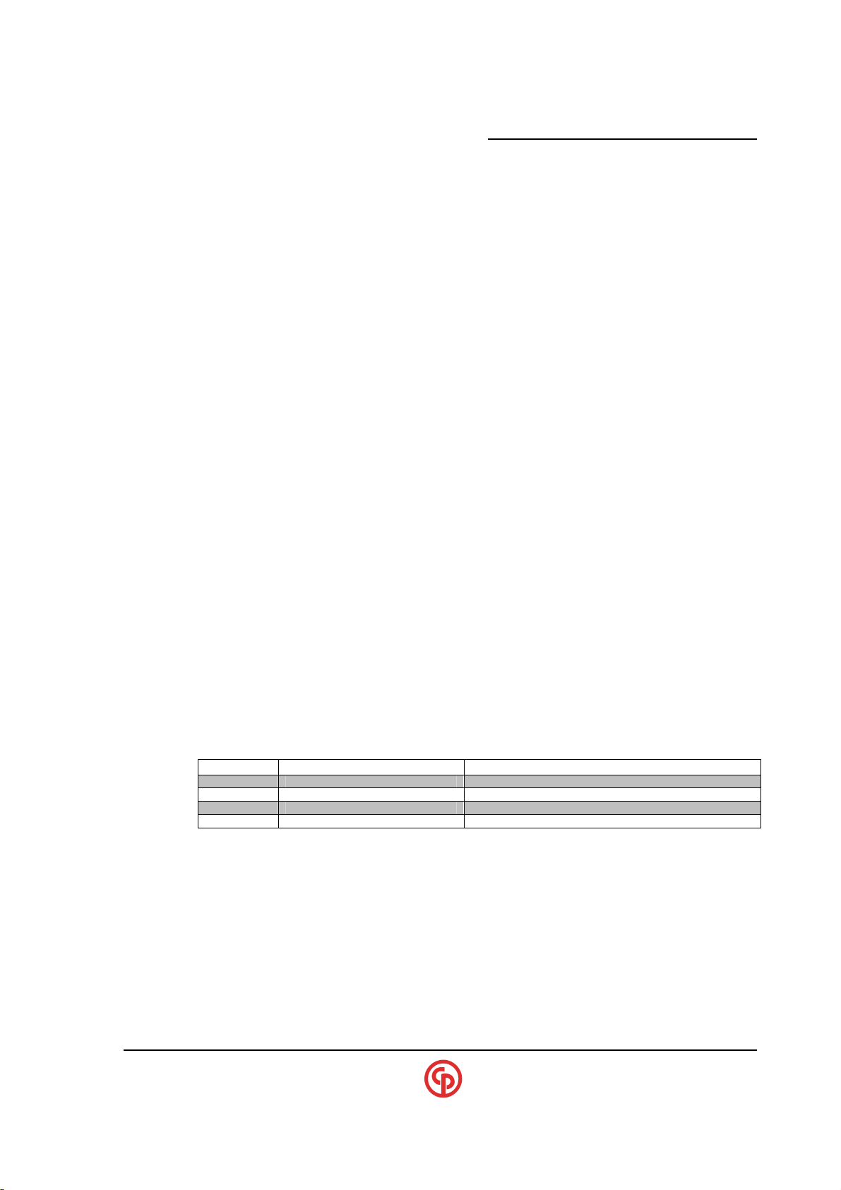
Determining INPUT Sources
It is possible that INPUTS can enter into the single-channel CS4700 Controller from several sources.
Below is a list of some potential sources and their relative priority.
1. VsSetup assignments
a. Tool switches
b. Digital inputs (via a 19-pin connector etc.)
c. Auto-increment or barcode-based pset selections
2. Ford specific I/O (but only if the Ford interface is enabled via the console port)
3. Keypad pset selection (if a keypad is resident and enabled by default or via the console)
4. Fieldbus (which must be enabled by “defaults” via keypad or console)
Note that if no keypad is present (Defaults should be set via the console)
5. OPC inputs via Visual Supervisor/Applicaton programs
CS4100/2100 Controllers Technical Reference
NOTE:
?
Examples:
You want to start the tool via Fieldbus. Set Default#1 below.
NOTE:
?
You want to start the tool via OPC. Set Default#3 below. You must run VsSetup and unmap the
cycle-On input from the tool switch.
DEFAULTS INPUT Mapping from the Keypad (or RS-232 Console)
In order to initiate a CS47XX/2700 Controller to operate without using VS, several “Default” modes
have been provided. These can be selected via the Main Menu screen or by invoking the console
“Default” command. The Default selections allow the user to select the source of the pset-selects and
the location from which the tool will be controlled. The 4 selections are:
Fieldbus Fieldbus
Fieldbus Operator switches on tool
DCM physical I/O (or OPC) Operator switches on tool (or OPC)
Keypad Operator switches on tool
Enabling Fieldbus will block all INPUTS from OPC.
If VsSetup is run and “Cycle-On” is mapped to a tool trigger or
an input, it will then override the Fieldbus input.
IMPORTANT
NOTE:
?
____________________________________________________________________________________________
September 2005 Page 29
Selecting Default 1 or 2 (Fieldbus) will block any OPC changes. This
is important if VS is connected to a system running any Fieldbus I/O.
Also, Default #1 is SUGGESTED for any variations of Fieldbus
control, such as “Cycle-enable” from the PLC but the operator
wants to run the tool from the tool switches etc.
Page 32
xxxxxxxxxx CS2700/4700 Controllers Technical Reference_________________________________________
DCM Input
DEFAULT#1
DEFAULT#2
DEFAULT#3
DEFAULT#4
DCM Output
DEFAULT#1,2,3 or 4
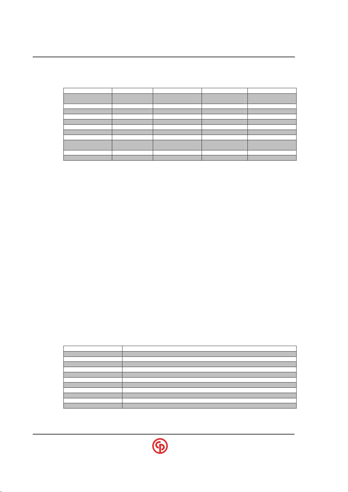
For reference, the table below shows the input mapping for the DCM when one of the above defaults
(in the prior table) is selected. (For GM- or FORD-specific default input mapping, see the GM/Ford
special applications section).
Input#1 Cycle-on,Enable,
Clear outputs
Input#2 Forward Forward Forward
Input#3 Pset select 0
Input#4 Pset select 1
Input#5 Pset select 2
Input#6 Sync. Sync. Sync. Sync.
Input#7 Calibrate Calibrate Calibrate Calibrate
Input#8
Tool Cycle trig. Cycle-on,Enable,
Clear outputs
Tool Direction Sw Forward Forward Forward
Tool Aux. Sw.
Cycle-on,Enable,
Clear outputs
Cycle-on,Enable,
Clear outputs
Cycle-on,Enable,
Clear outputs
Cycle-on,Enable,
Clear outputs
OPC INPUTS for the CS4700 Controller
The OPC inputs (Cycle-On, Pset Select, etc.) via the computer through VsMain, although seldom
used, are available and have been used in some applications. A CS4700 Controller without a CCM
will work as it always has. However, a CS4700 with a CCM and either a Keypad/Display or Fieldbus
connection may or may not allow OPC inputs. In order for specific OPC inputs to operate the CS4700
Controller, Default #3 above must be selected via defaults (and those specific inputs unmapped
accordingly by VS).
Fieldbus INPUTS for the CS4700 Controller
In order for inputs to be sourced from a fieldbus, the controller must be equipped with the appropriate
AIM and fieldbus hardware. It is important to select “DEFAULT” (via keypad or console) for the
source of the inputs. For example, DEFAULT 1 or DEFAULT 2 would be necessary selections for
achieving reliable fieldbus inputs, especially if DEFAULT 3 or DEFAULT 4 can later override the
selected “inputs” and basically “take away” the fieldbus input via OPC.
Input Ownership
The Console command “Status” will report the ‘owner’ of the most popular inputs. The CCM will
“own” the input if the keypad, fieldbus or the Ford-function has control. The DCM will “own” the
input if the input is sourced from the tool, physical inputs, OPC, or (barcode or auto-increment).
OUTPUTS (When Defaults are Selected on Keypad/Console)
(For GM specific default-output mapping see later section).
Output#1 Finished
Output#2 Good
Output#3 Bad
Output#4
Output#5 In-Cycle
Output#6
Output#7 Direction
Output#8 Sync.
Tool YELLOW U.S. Standard Yellow
Tool GREEN U.S. Standard Green
Tool RED U.S. Standard Red
____________________________________________________________________________________________
Page 30 39-30-43083
Page 33
_____________________________________________________
DeviceNet
SW.1 SW.
MAC Sw3 Sw4 Sw5 Sw6 Sw7 Sw8
STATE
Descr
iption
LED1-Reserved
---
LED2-
Network
Off
Off or Not online
LED3-
Module
Off
No power to device
LED4-
Reserved
PIN SIGNAL
1 V-
2 CAN_L
PIN SIGNAL
1
Shield
2
V+ (+24vdc)
CS4100/2100 Controllers Technical Reference
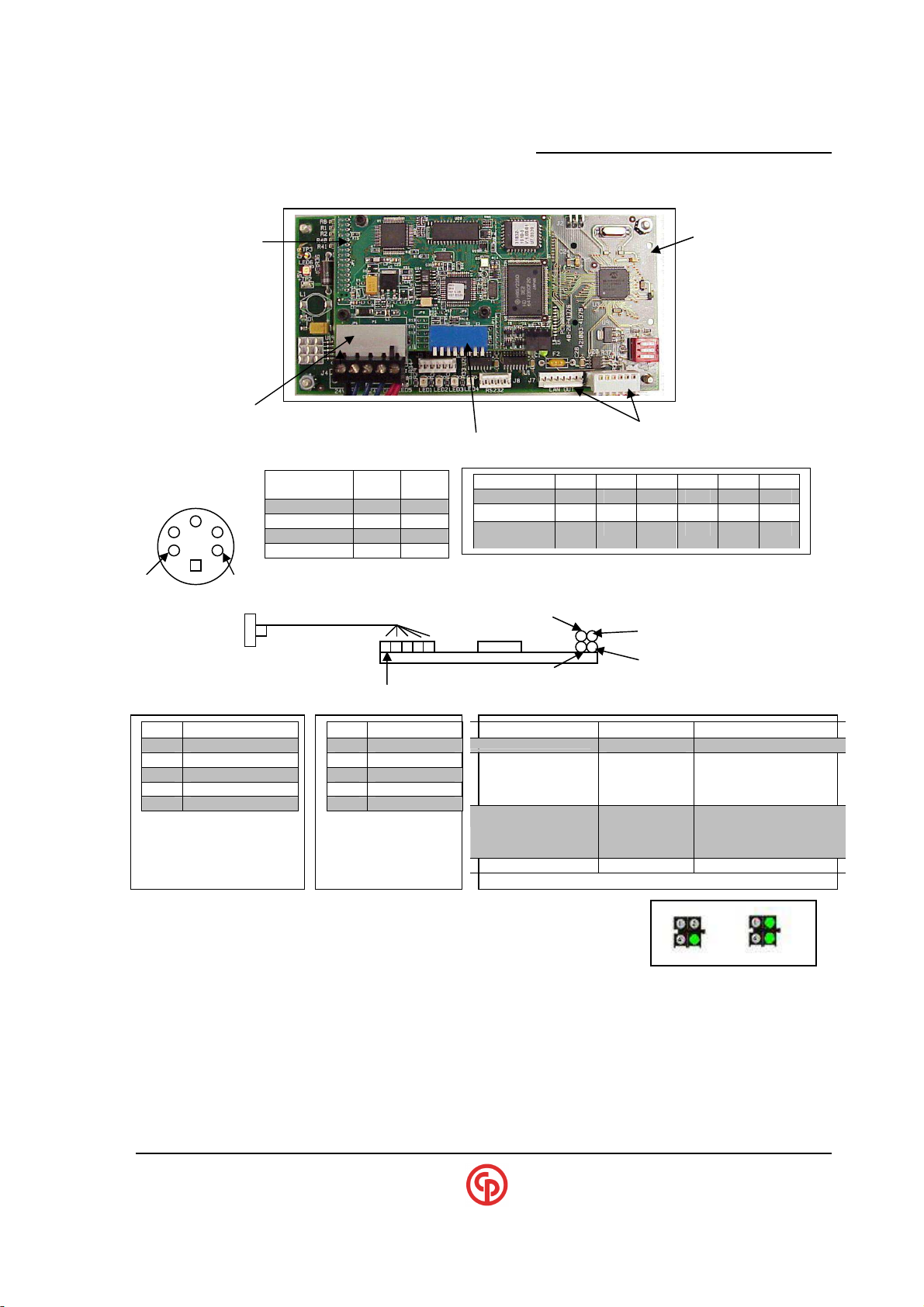
DeviceNet (Slave) Setup and Configuration
Anybus
DeviceNet card AIM board
(see AIM section)
(see below for pinout) (CAN connections)
8 Position Dip switch settings on “DeviceNet” card
.
5-pos DeviceNet connector Internal X-bus
Baud Rate
125k OFF OFF
250k OFF ON
500k ON OFF
(Reserved) ON ON
2
0 Off Off Off Off Off Off
1 Off Off Off Off Off On
2 Off Off Off Off On Off
5 1
5-pin Mini (male)
(Bulkhead)
(Internal) DeviceNet Card (Side View)
LED #1
LED #2
LED #3
Mating cable for Mini conn: LED#4
Turck# B4151-0113.5 Pin #1 of 5 position connector on PC board
CP Techmotive#26-20-6740
3 V- (0 volt)
4 CAN_H
5 CAN_L
5 pin “Mini-style”
Bulkhead connector
By Default, 24vdc is expected to be supplied from
the DEVICENET network (See pin-2 above).
3 Shield
4 CAN_H
5 V+
5 pin “Phoenix” style
connector on pc
board
Status
Status
Green steady
Green flash
Red steady
Red flash
Green steady
Green flash
Red steady
Red flash
---
Line OK, online, connected
On-line, not connected
Critical link failure
Connection timeout
Device Operational
Data size bigger than config.
Unrecoverable fault
Minor Fault
Status Indicators
Once the controller is powered up and the Devicenet module is initialized, LED #3 will be green, and
all others will be off (#2 may be flashing green, this is OK). Once communications is established with
the master, LED#2 will be steady green and LED#3 will remain on (as shown, above).
EDS file
An EDS file is available upon request which is applicable to this DeviceNet ANYBUS card.
____________________________________________________________________________________________
September 2005 Page 31
Page 34

xxxxxxxxxx CS2700/4700 Controllers Technical Reference_________________________________________
>
aim
Fieldbus Diagnostics Example for DeviceNet
(Debug Console)
Anybus Interface Module is active.
HW Config: 00, SW Version: 1.01
I/O mode: gm4 (4 bytes in, 4 bytes out)
Anybus Module is attached.
Vendor ID: 1
Serial Number: A0017B83
Module SW Version: 1.09
Boot Loader Version: 1.34
Fieldbus Type: 25 - DeviceNet
Dip Switches: 0xBC
Address: 60
Baudrate: 500
AppInt SW Version: 2.16
Fieldbus SW Version: 1.06
Anybus Module is initialized.
Anybus Module is online.
Inputs from fieldbus = 00 00 00 00
Inputs to DCM = 00 00 00 00
Outputs = 00 00 00 00
>aim ?
'aim' - Displays AIM status.
'aim io' - Display the current state of the AIM I/O.
'aim +diag' - Output AIM diagnostic data to the console.
'aim -diag' - Turn off AIM diagnostic output.
'aim setmode <mode>' - Sets fieldbus mode.
modes:
default (1 byte in, 7 bytes out)
std (1 byte in, 48 bytes out)
gm4 (4 bytes in, 4 bytes out)
gm8 (8 bytes in, 4 bytes out)
'aim config' - Display DeviceNet node configuration.
'aim config addr<0 to 63> baud< 125,250,or 500 >'\n"
- Modifiy DeviceNet address/baud rate.
'aim config setmode <mode>'
modes:
ccm (get addr/baud from the ccm)
switches1 (get addr/baud from switches)
switches2 (switches reverse ordered)
'aim byteorder big' - Configure for big endian (Motorola style) byte order
'aim byteorder little' - Configure for little endian (Intel style) byte order
'aim commit' - Commit AIM settings to EEPROM storage.
>aim config
address : 60
baud : 500
mode : switches1
____________________________________________________________________________________________
Page 32 39-30-43083
Page 35
_____________________________________________________
CS4100/2100 Controllers Technical Reference
Profibus (Slave) Setup and Configuration
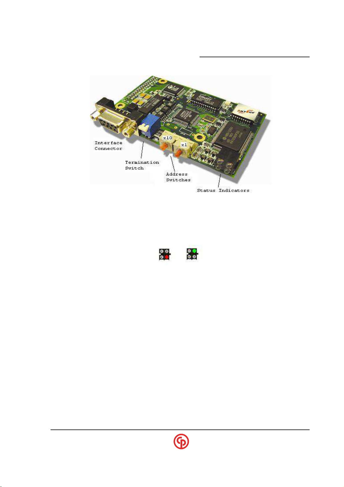
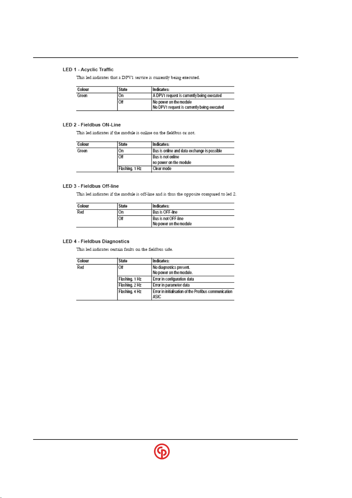
Profibus Module Status Indicators:
Once the controller is powered up and the profibus module is initialized, LED #3 will be red, and all
others will be off. Once communications is established with the master, LED#2 will be green, and all
others will be off. (as shown)
____________________________________________________________________________________________
September 2005 Page 33
Page 36
xxxxxxxxxx CS2700/4700 Controllers Technical Reference_________________________________________
____________________________________________________________________________________________
Page 34 39-30-43083
Page 37

_____________________________________________________
Profibus Network Configuration
Before the module can be used on a Profibus-DP network some basic settings must be configured.
Baud Rate
The baud rate on a Profibus-DP network is set during configuration from the master. The module
features auto baud rate detection and the user does not have to configure the baudrate.
Supported baud rates:
1. 9.6 kbit/s
2. 19.2 kbit/s
3. 45.45 kbit/s
4. 93.75 kbit/s
5. 187.5 kbit/s
6. 500 kbit/s
7. 1.5 Mbit/s
8. 3 Mbit/s
9. 6 Mbit/s
10. 12 Mbit/s
Node Address
The switches can be used when selecting a node address in the range 00-99.
Termination
Each bus segment in a Profibus network must be terminated properly to ensure error-free operation.
If the module is used as the first or last node in a network, the termination switch has to be in ON
position. Otherwise the switch has to be in OFF position.
CS4100/2100 Controllers Technical Reference
NOTE:
?
If an external termination connector is used, the switch must be
in the OFF position.
GSD Configuration file
A GSD file is available upon request which is applicable to this Profibus-DPV1 ANYBUS card.
____________________________________________________________________________________________
September 2005 Page 35
Page 38

xxxxxxxxxx CS2700/4700 Controllers Technical Reference_________________________________________
Fieldbus Diagnostics Example for Profibus
(Debug Console)
=======================================================================
Profibus
=======================================================================
>
aim
Anybus Interface Module is active.
HW Config: 00, SW Version: 1.02E
I/O mode: default (1 byte in, 7 bytes out)
Anybus Module is attached.
Vendor ID: 1
Serial Number: A001B143
Module SW Version: 1.00
Boot Loader Version: 1.34
Fieldbus Type: 5 - Profibus-DPV1
Switches 25
Node Address 25
AppInt SW Version: 3.00
Fieldbus SW Version: 1.35
Anybus Module is initialized.
Anybus Module is not online.
>
aim ?
'aim' - Displays AIM status.
'aim io' - Display the current state of the AIM I/O.
'aim +diag' - Output AIM diagnostic data to the console.
'aim -diag' - Turn off AIM diagnostic output.
'aim setmode <mode>' - Sets fieldbus mode.
modes:
default (1 byte in, 7 bytes out)
std (1 byte in, 48 bytes out)
gm4 (4 bytes in, 4 bytes out)
gm8 (8 bytes in, 4 bytes out)
'aim config' - Display Profibus node address
'aim config addr<0 to 126>' - Modify Profibus node address
'aim config setmode <mode>'
modes:
ccm (get addr from the ccm)
switches (get addr from switches)
'aim byteorder big' - Configure for big endian (Motorola style) byte order
'aim byteorder little' - Configure for little endian (Intel style) byte order
'aim commit' - Commit AIM settings to EEPROM storage.
>
aim config
address : 25
mode : switches
____________________________________________________________________________________________
Page 36 39-30-43083
Page 39
_____________________________________________________
CS4100/2100 Controllers Technical Reference
Ethernet/IP or Modbus/TCP (Slave)
Setup and Configuration
____________________________________________________________________________________________
September 2005 Page 37
Page 40

xxxxxxxxxx CS2700/4700 Controllers Technical Reference_________________________________________
NOTE:
?
Ethernet-IP/Modbus-TCP are considered fieldbus entities. Look
for the settings to be “AIM” commands rather than “ipconfig”
commands.
How to change between Ethernet IP and Modbus TCP Server Modes
To set to Modbus mode using the diags console, at the console prompt type aim config +modbus, then
press enter. This will disable the EthernetIP server on the anybus module.
>aim config +modbus
To set to EthernetIP mode using the diags console, type aim config +ethip, then press enter. This will
disable the Modbus-TCP server on the anybus module.
>aim config +ethip
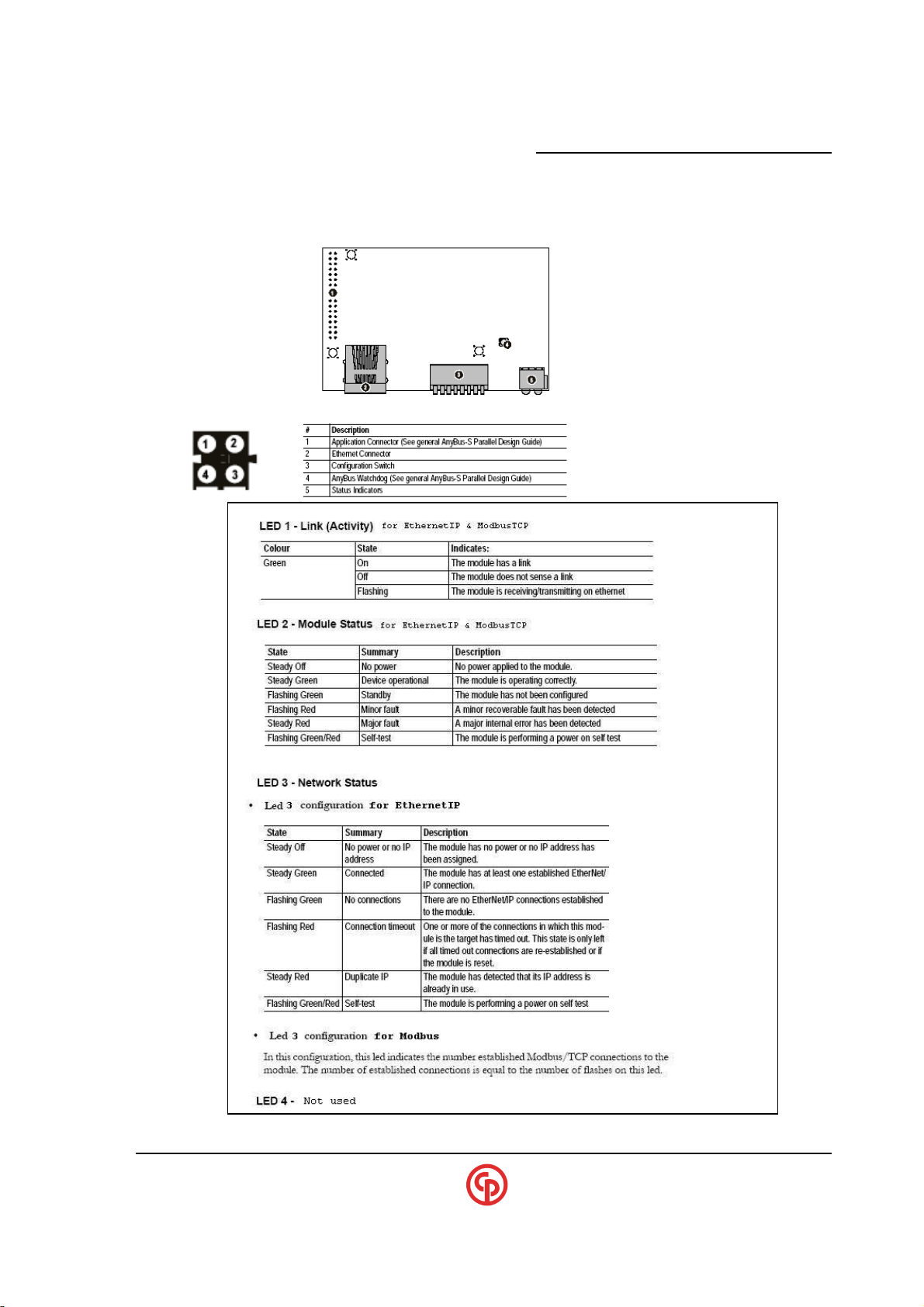
LED functionality
For EthernetIP mode:
LED#3 will be solid green when the Master is connected (online).
LED#3 will flash green (at 1hz) when the Master is not connected (offline).
For ModbusTCP mode:
LED#3 will flash green when the Master is connected (online).
LED#3 will be off when the Master is not connected (offline).
DIP switch functionality
These switches are generally not used. It is possible to select the ARP setting (instead of CCM)
in the Console setup (“AIM CONFIG SETMODE” command). However the settings will be
forced to 192.168.0.n with a Mask of 255.255.255.0. Typically, the CCM mode is selected and
the user can have full control of setting the IP, Mask and Gateway settings.
>aim config setmode ccm
EDS configuration file
An EDS file is available upon request which is applicable to this Ethernet-IP capable card.
Modbus-TCP Special Information
Reading Outputs
The start address (byte zero) for reading outputs begins at address 0hex.
Writing Inputs
The start address (byte zero) for writing inputs begins at address 400hex (1024 decimal).
____________________________________________________________________________________________
Page 38 39-30-43083
Page 41

_____________________________________________________
CS4100/2100 Controllers Technical Reference
Fieldbus Diagnostics Example for Ethernet-IP Setup
(Debug Console)
=======================================================================
EthernetIP (or Modbus-TCP)
=======================================================================
>
aim
Anybus Interface Module is active.
HW Config: 00, SW Version: 1.01
I/O mode: gm4 (4 bytes in, 4 bytes out)
Anybus Module is attached.
Vendor ID: 1
Serial Number: A001B126
Module SW Version: 1.23
Boot Loader Version: 1.18
Fieldbus Type: 83 - Ethernet IP+IT
Dip Switches: 0x0
AppInt SW Version: 3.01
Fieldbus SW Version: 1.23
Anybus Module is initialized.
Anybus Module is online.
>
aim ?
'aim' - Displays AIM status.
'aim io' - Display the current state of the AIM I/O.
'aim +diag' - Output AIM diagnostic data to the console.
'aim -diag' - Turn off AIM diagnostic output.
'aim setmode <mode>' - Sets fieldbus mode.
modes:
default (1 byte in, 7 bytes out)
std (1 byte in, 48 bytes out)
gm4 (4 bytes in, 4 bytes out)
gm8 (8 bytes in, 4 bytes out)
'aim config' - Displays anybus module TCP/IP configuration.
'aim config addr <ip addr> mask <subnet mask> gateway <gateway>'
- Modifies anybus module TCP/IP configuration.
'aim config setmode <mode>' - Determines where to get the IP settings
modes:
ccm - IP settings from the ccm
arp - IP settings from External source
See module document
'aim byteorder big' - Configure for big endian (Motorola style) byte order
'aim byteorder little' - Configure for little endian (Intel style) byte order
'aim config +EthIP' - connection type is EthernetIP
'aim config +Modbus' - connection type is Modbus
'aim commit' - Commit AIM settings to EEPROM storage.
>
aim config
IP Address : 10.120.18.31
Subnet Mask : 255.255.252.0
Default Gateway : 10.120.16.1
mode : ccm
connection : EthIP or “Modbus” if setup for Modbus-TCP
Physical Address : 00-30-11-02-15-56
____________________________________________________________________________________________
September 2005 Page 39
Page 42
xxxxxxxxxx CS2700/4700 Controllers Technical Reference_________________________________________
RS-232
Remote
Ethernet
Battery
SDLC to external
SDLC to TCM
SDLC Address
Options
Diagnostic
(JP3) X
-
bus (CAN)
JP1 –
Battery connect
Optional PC-boards (Technical Details)
.
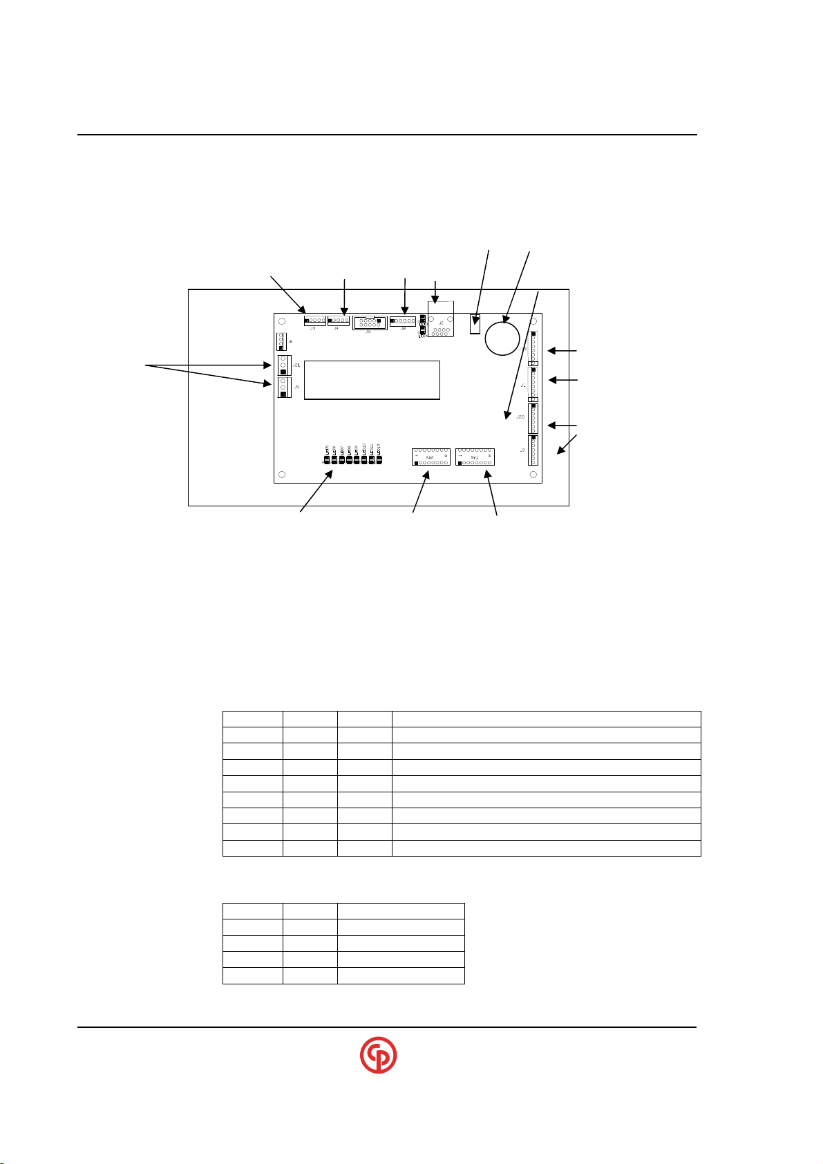
Communications Control Module (+) (CCM - CP p/n 420981-40311)
RS-232 Diag
24 VDC in/out
LED5 Green - Flashes when software is running
LED6 Yellow - Comm. to TCM via RS485/SDLC
LED7 Red – Future
LED8 Red - VS Comm. on Ethernet activity
LED9 Red - Specialty interface activity (PFCS, GM or FORD)
LED10 Red - Techmotive API activity
LED11 Red - (Internal) X-bus activity
LED12 Red - Future
LEDS
Options SW2
Switch #1 - Force CCM into FLASH mode
Switch #2,3,4
Sw #2 Sw #3 Sw #4 Special Forced Comm. protocol
Switch #7 & 8 - Sets internal CAN bus baud rate (Set for 500k default….see table)
Sw #7 Sw #8 CAN baud rate
to non-volatile memory
Flash/VS
CCM PLUS
MAC address etc.
LEDs
SW2
10-base-T
JP3
SW1
0 0 0 No Forced protocol (Console can change protocol)
1 0 0 Enable Chrysler PFCS Protocol
0 1 0 Enable GM Ethernet Protocol
1 1 0 Enable FORD Ethernet Protocol
0 0 1 Reserved
1 0 1 Reserved
0 1 1 Reserved
1 1 1 No Forced protocol (Console cannot change protocol)
0 0 125k
1 0 250k
0 1 500k *
1 1 20k
#DL2430
Termination jumper
network
CAN In & Out
____________________________________________________________________________________________
Page 40 39-30-43083
Page 43
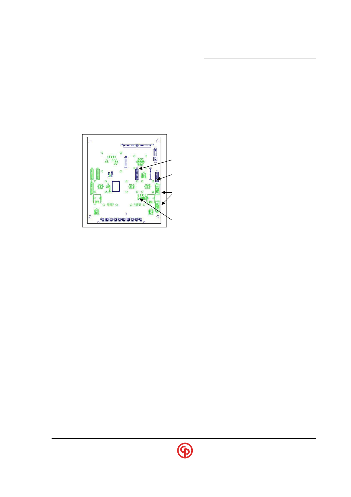
_____________________________________________________
Bottom Connector board connector layout
External SDLC (connects to CCM+ “SDLC
-
B”
CCM to TCM SDLC Connection
(connects to CCM+ “SDLC
-A”
(RS-232) COM2: connects to CCM+ “Com0”
Thes jumpers must be open so that the External RS
-
232
CCM FIELD UPDATES
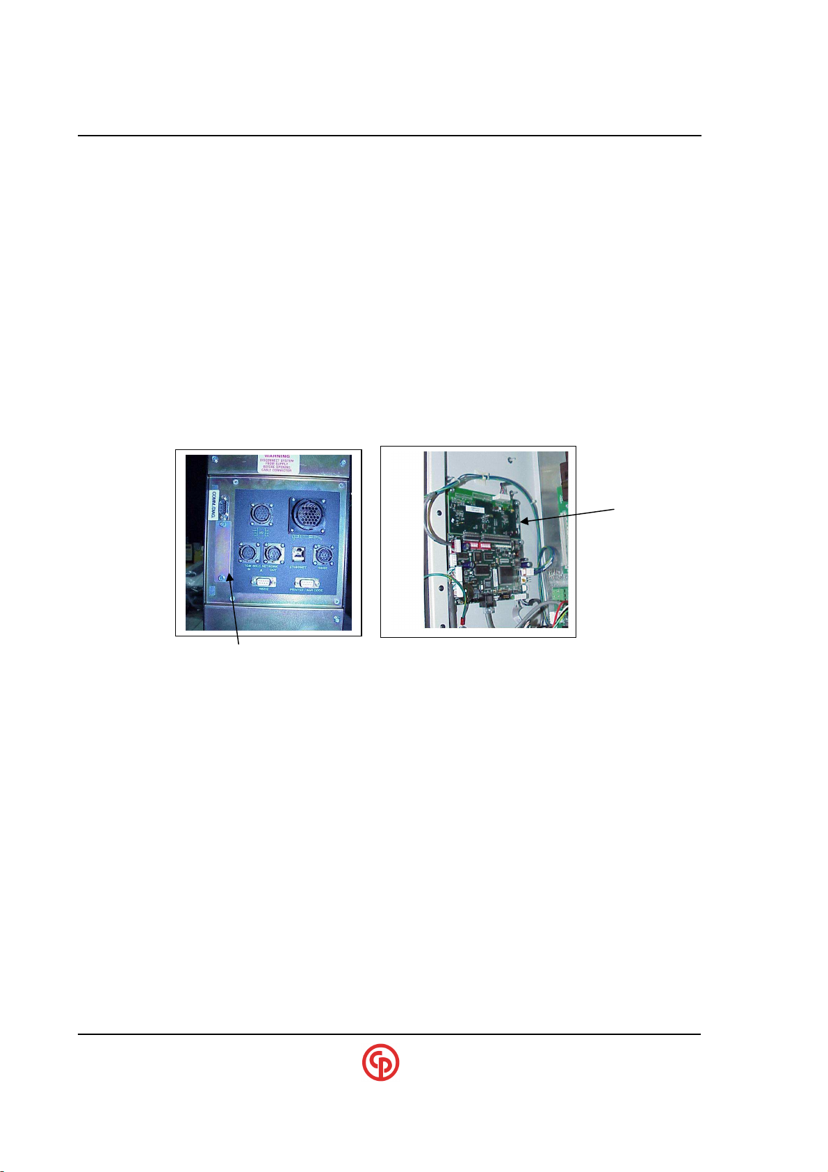
The CCM may require software updates in the field. CP Techmotive’s Winflash utility should work as
it does normally with the existing TCM product.
When the CCM PLUS is used, the RS-232 port that is used for VS-detachable now also becomes
the FLASH port for DCM,CCM and all internal boards downstream from the CCM. Therefore, it is
not necessary to go inside the CS47XX/2700 and move cables to FLASH upgrade.
(This version is required for CCM+ with SDLC capability.)
Note that COM2: might be the upper or lower connector,
depending on the assembly.
does not go to the TCM when a CCM+ is present, etc.
CS4100/2100 Controllers Technical Reference
EXTERNAL SDLC Networking on CS4700’s Equipped
with a CCM+
CS4700s can be networked with RS485/SDLC multi-drop communications. This is true even for
units that are equipped with CCM+ for ethernet capability. (However the CS2700 equipped with the
CCM+ is NOT capable of SDLC communications.
Additionally, when the CCM+ is used in conjunction with VS3.30 or higher, the CCM’s real time
clock will get time-synchronized automatically with the computer that is connected to it that is
running VS (either embedded or a detachable).
Make sure to set the proper SDLC (RS-485) address on the CCM. This is different than on CS4700’s
that are not supplied with a CCM, as the SDLC (RS-485) address on these units is set on the TCM’s
backplane. On CS4700’s equipped with a CCM, the address of the tool control module (TCM), which
is on its own backplane, must be set to 1.
Internal (CAN-BUS) Operation
The CCM communicates to downstream devices – the AIM for Fieldbus and TDM for the
keypad/display – via an internal CAN bus. The Communication is based on CANBUS. When
upgrading or debugging, it is important to understand some of the characteristics of this bus.
Make sure that the CCM and all downstream devices are talking at the same baud rate. The
recommended setting is 500 kbaud (see the DIP switches on the PC boards etc.). Also be sure that a
“Termination Resistor” is turned-on at opposite ends of the CAN-Bus network. If the CCM has no
____________________________________________________________________________________________
September 2005 Page 41
Page 44
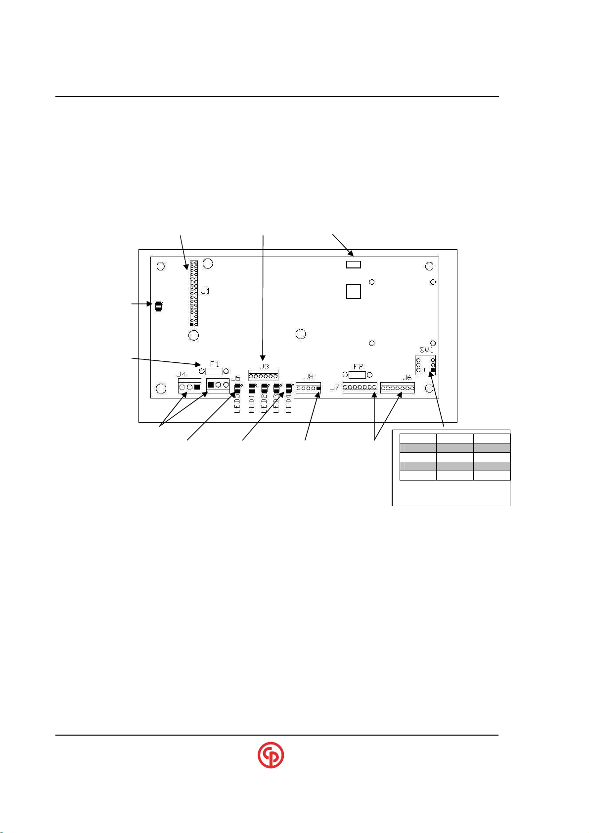
xxxxxxxxxx CS2700/4700 Controllers Technical Reference_________________________________________
Sw.2 Sw.3 Baud
0 1 500k*
downstream devices, the baud rate and the termination resistor do not matter. Typically, these will be
set properly at the factory, but this could become an issue on a field-upgrade. If the baud rates are
wrong, the devices will not communicate at all. If the baud rate is correct, but the termination is
wrong, communication may be intermittent; for example, it may appear to operate properly but
flashing downstream will not work, etc.
AIM Module (CP part# 421003-41375)
(Used in Fieldbus options)
(Typically not needed)
ANYBUS card connection (Future) (Flash program port (Direct to PIC)
(RED) 5Volts
(Future) 24v fuse
( 24vdc) Green Flashing RS-232 CAN in/out
(24vdc in/out)
AIM running (Not used) 5vdc input
0 0 125k
1 0 250k
1 1 20k
Sw.1 = CAN Termination
____________________________________________________________________________________________
Page 42 39-30-43083
Page 45
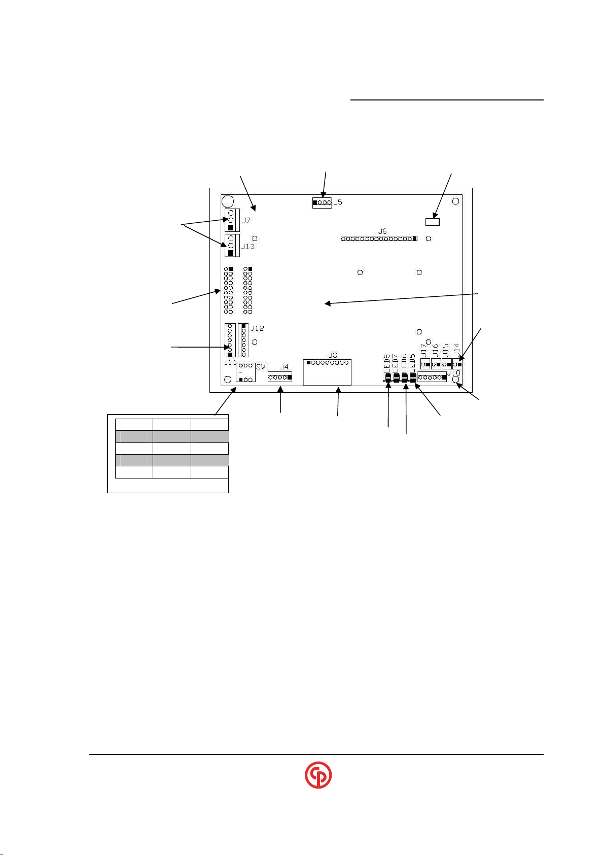
_____________________________________________________
Sw.2
Sw.3
Baud
Sw.1 = CAN
CS4100/2100 Controllers Technical Reference
TDM Module (CP part# 421000-41298)
(Used in Keypad/Display option)
24vdc LED To LED Display backlight (Flash port (Direct to PIC)
CAN in/out J16 - LED G
RS-232 To Keypad Key-press
24vdc in/out
To Display
J17 – LED Y
J15 - LED R
(Not used) Blinks
0 0 125k
if running CCM comm. problem
1 0 250k
0 1 500k*
1 1 20k
5v LED2
New REV. TDM’s
R,G,Y connector
____________________________________________________________________________________________
September 2005 Page 43
Page 46
xxxxxxxxxx CS2700/4700 Controllers Technical Reference_________________________________________
SPECIAL APPLICATION: PFCS
Important note:
into the console for units with a keypad/display. The CCM’s SW2 (2nd dip switch) can
force PFCS to be enabled. A special menu will then be available which will permit all of the
PFCS configurations.
CCM1.12 adds the ability to configure PFCS without the need to enter
(Ethernet or Terminal Server)
Setting up to Link to a PFCS Host on Ethernet
1. Type “ipconfig +pfcs” to enable the PFCS client in the CS47XX/2700 Controller.
2. Type “pfcs mode ethernet” to configure PFCS for Ethernet operation
3. Use the “pfcs addr <ip addr>” and “pfcs port <port> “ to enter the PFCS server info.
4. See below for details in using the Barcode/Buffer or Custom Machine-ID options.
5. When complete be sure to use the “pfcs commit” command
6. Use the “pfcs +diag” command to assist in debugging
Asynch Daughter
(Attached to CCM)
Location of 25Pin-D
PFCS Terminal Server connector
Setting up to Link to a PFCS Host on Terminal Server (RS232)
1. Verify the controller has the add-on Asynch Daughter board & DB25 connector on the enclosure
2. Connect the DB25 cable from the PFCS Terminal Server to the controller
3. Type “ipconfig +pfcs” to enable the PFCS client in the controller
4. Type “pfcs mode terminalserver” to configure the PFCS client for (RS232)
5. See “pfcs ?” for details to set one of several options (ACK timeouts, Retries & other options)
6. When settings are complete type “commit” to save the settings
7. You can use the “pfcs start” or “pfcs stop” command although on power up PFCS will start auto.
Using Barcodes, Buffering and Machine IDs with PFCS
In order for the “avi” or “vin” data to be included in the packets to PFCS, the Model-Number or PartID functions must be enabled with VS “system settings.”
NOTE:
?
When using the “+psetid”, the Machine ID will be derived from the first four characters of the TCM’s parameter set
name that ran the cycle. VS must be used to establish parameter set names etc.
____________________________________________________________________________________________
Page 44 39-30-43083
PFCS buffering will not work unless either the “avi” or “vin” is
enabled. Also, the TCM may need to be set up for “VIN” history
mode with the VS “system settings” program (for model number
applications).
Page 47

_____________________________________________________
CS4100/2100 Controllers Technical Reference
If controller is equipped with a “Keypad Display”
The DIAG screen on the display will show the condition of the PFCS connection as either “OK” or “Err”.
Whether the unit has a “Keypad Display” or not, the console can provide more extensive diagnostics information.
PFCS Ethernet Setup example: <Debug Console>
==================================================================
>ipconfig ?
'ipconfig' - Displays TCP/IP configuration.
'ipconfig addr <ip addr> mask <subnet mask> gateway <gateway>'
- Modifies TCP/IP configuration.
'ipconfig +api' - Enables the Techmotive API Server.
'ipconfig -api' - Disables the Techmotive API Server.
'ipconfig +ford' - Enables the Ford interface.
'ipconfig -ford' - Disables the Ford interface.
'ipconfig +gm' - Enables the GM interface.
'ipconfig -gm' - Disables the GM interface.
'ipconfig +pfcs' - Enables the PFCS interface.
'ipconfig -pfcs' - Disables the PFCS interface.
'ipconfig +vseth' - Enables the Visual Supervisor Ethernet bridge.
'ipconfig -vseth' - Disables the Visual Supervisor Ethernet bridge.
'ipconfig +vssdlc' - Enables the Visual Supervisor SDLC bridge.
'ipconfig -vssdlc' - Disables the Visual Supervisor SDLC bridge.
'ipconfig commit' - Commits IP configuration to EEPROM.
>ipconfig +pfcs
Starting PFCS Client.
Ethernet Adapter CS8900A
Physical Address : 00-05-6B-07-01-00
DHCP Enabled : No
IP Address : 10.120.17.27
Subnet Mask : 255.255.252.0
Default Gateway : 0.0.0.0
External Interfaces Enabled:
Visual Supervisor Bridge
PFCS Client
>pfcs ?
'pfcs' - Displays PFCS client configuration.
‘pfcs mode <mode> -Sets mode to « Ethernet » or « Terminal Server »
'pfcs start' - Connect to the PFCS server.
'pfcs stop' - Disconnect from the PFCS server.
pfcs stats' - Display PFCS communication statistics.
'pfcs stats clear' - Clear PFCS communication statistics.
'pfcs +diag' - Output PFCS diagnostic data to the console.
'pfcs -diag' - Turn off PFCS diagnostic output.
'pfcs addr <ip addr>' - Sets PFCS server IP address.
'pfcs port <port>' - Sets PFCS server port.
'pfcs retries <n>' - Sets Max Retries to <n> (1<=n<=10).
'pfcs ack <n>' - Sets Ack Timeout to <n> seconds (1<=n<=10).
'pfcs keepalive <n>' - Sets Keep Alive Interval to <n> seconds (30<=n<=240)
'pfcs reconnect <n>' - Sets Reconnect Interval to <n> seconds.
'pfcs +psetid' - Machine ID for rundowns will use PSet Name.
'pfcs -psetid' - Machine ID for rundowns will be assigned by PFCS.
'pfcs avi' - PFD will send AVI barcode with results.
'pfcs vin' - PFD will send VIN barcode with results.
'pfcs nobarcode' - PFD will not send barcode with results.
'pfcs +buffer' - Enables buffering of rundowns.
'pfcs -buffer' - Disables buffering of rundowns.
'commit' - Commit PFCS settings to EEPROM storage.
____________________________________________________________________________________________
September 2005 Page 45
>pfcs addr 10.120.16.116 [Note: This is the IP address of the PFCS host
PFCS is enabled.
PFCS Server Address : 10.120.16.116
PFCS Server Port : 16101
]
Page 48

xxxxxxxxxx CS2700/4700 Controllers Technical Reference_________________________________________
Max Retries : 3
Ack Timeout : 5 seconds
Keep Alive Interval : 120 seconds
Reconnect Interval : 10 seconds
Barcode disabled.
Result buffering disabled.
Machine ID assigned by PFCS.
>pfcs port 16101
PFCS is enabled.
PFCS Server Address : 10.120.16.116
PFCS Server Port : 16101
Max Retries : 3
Ack Timeout : 5 seconds
Keep Alive Interval : 120 seconds
Reconnect Interval : 10 seconds
Machine ID assigned by PFCS.
Barcode disabled.
Result buffering disabled
[Enter any other applicable pfcs commands (MachID,Buffer options etc.]
.
>pfcs commit
Writing changes to EEPROM...
*** WARNING! DON'T POWER DOWN UNTIL EEPROM WRITE IS DONE!
>EE
Initalizing CCM
Loading FPGA...
Initalizing EEPROM Data...
Initializing System Time: Wed Aug 20 13:43:22 2003
Starting TCP/IP.
IP Address 10.120.17.27
Starting VS Bridge on port 5000.
Initializing RS-232 Communication.
Initializing SDLC Communicaton.
System is coming up...
*********************************************************
Communication Control Module CCM Debugging Console V1.01
Copyright© 2003 CP-GSE Techmotive Tool
*********************************************************
Hello.
>pfcs +diag [Use this command to view PFCS running diagnostics]
____________________________________________________________________________________________
Page 46 39-30-43083
Page 49
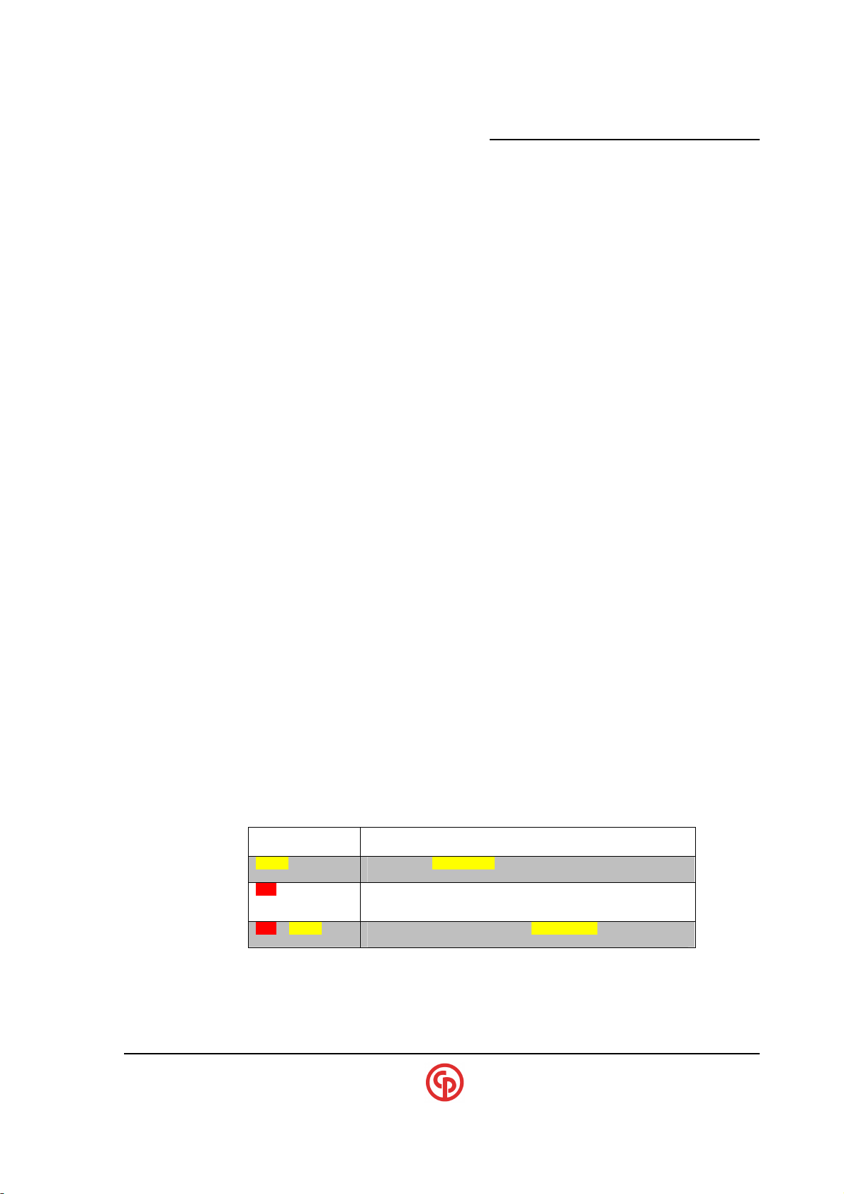
_____________________________________________________
LIGHT
GENERAL PROCEDURE
(Conditions applicable to torque control)
CS4100/2100 Controllers Technical Reference
SPECIAL APPLICATION: GM
The CS47XX/2700 Controller has an Ethernet interface that complies with the latest specification for
sending data to the GM server. It also has a DeviceNet interface that complies with the GM
specification.
Note that it with Keypad/Display units that much of the below configurations can be done by setting
the CCM SW2 DipSwitch #3 to force the GM Driver to be enabled and using the keypad to make the
appropriate setups.
Here are the general setup instructions (If using the console):
1. Enable the GM Ethernet interface via the RS-232 console {“ipconfig +gm”}
2. Enter the GM Server IP address via the RS-232 console
NOTE:
?
3. Set up the appropriate GM I/O fieldbus mapping via the RS-232 console. Refer to the Fieldbus
Section (GM4 or GM8 I/O) {“aim setmode gm4”}
4. Set defaults using either the RS-232 console or the keypad. You should select one of the
“fieldbus” defaults to block “OPC.”
5. Set up the fastening strategy and parameter limits using the keypad or VS.
a. If GM (PVI’s) are being used, the Model# Barcode must be enabled and the minimum length
must be set to “1” in the VsSetup-barcode setup tab-mask.
b. In order for the GM host to be able to see the PVI, make sure the VIN-History mode for
Model# barcodes is enabled. This is done in VsSystemSettings.
IMPORTANT GM Information
The GM specification requires that certain algorithms and setpoints be used for compliance.
In general, when setting the defaults through the keypad, these are appropriately set except for
application customization of specific setpoints.
GM has adopted a general ‘standard’ which gives special meanings to the lights presented to the
operator.
The CS4700 Controller is considered the “slave” in this
configuration.
(General Assembly Engineering)
____________________________________________________________________________________________
September 2005 Page 47
Yellow The fastener can be rerun
TORQUE-LOW (unless ANGLE-HIGH)
Red The fastener must be backed out and replaced.
ANGLE-HIGH failure (or)
REMOVE-TORQUE-LIMIT exceeded
Red & Yellow The fastener must be backed but can be re-run
Failure conditions that do not show above.
Page 50

xxxxxxxxxx CS2700/4700 Controllers Technical Reference_________________________________________
In order to meet this specification and the required light patterns for all of the various conditions (not
shown here) here are some rules to setting up the controller:
1. The “GM” Red/Yellow/Green lights must be mapped instead of the standard R/Y/G lights
(This should already be done if “Defaults” were loaded after the box was set to GM mode)
2. The “REHIT” algorithm can be enabled if it is desired for the application. This is a special
monitor function to detect if an operator is trying to tighten an already tight fastener.
NOTE:
?
3. The “REMOVE-TORQUE-LIMIT” (on the pset Torque Monitor tab) must be set higher
than the “Torque-High” limit.
4. In order to guarantee the I/O timing over DeviceNet, a “Minimum Time between cycles” of a half
second should be entered (keypad defaults should set this already etc.).
5. “Slip – Detect” (on the pset Torque/Angle Control tab) can be enabled, if desired. This algorithm
is intended to stop the tool if the torque drops off significantly (for example, due to a broken bolt
or because a socket has slipped off, etc.)
For this “Slip-Detect” to function per the GM Specification, the controllers “Control Ref Torque”
must be equal to ZDR (or Threshold torque).
In most instances, VS should not be needed for the GM-required setup on units with a keypad/display;
Rather, select the GM Mode and use the set defaults as instructed above. If a VS-embedded
controller/PC is connected, be sure to select VIN History (Model#) mode as the GM host requires it.
The CS47XX controller for GM is special in that it must also be fitted with the appropriate GM
specified I/O connectors. Additionally, special provisions within the enclosure provide an isolated
24vdc supply for the DeviceNet function.
The REHIT “Stop Torque” parameter should be above the
“Threshold (ZDR)” limit and if you are using Torque Control, it
should be below the “Target Torque.”
____________________________________________________________________________________________
Page 48 39-30-43083
Page 51
_____________________________________________________
DEFAULT#
Parameter Set Select
Tool Running control
DCM Input
DEFAULT#1
DEFAULT#2
DEFAULT#3
DEFAULT#4
Input#4
Cycle-on Cycle-on Cycle-on
Input#5
Release One Job
Release One Job
Release One Job
Release One Job
DCM Output
DEFAULT#1,2,3 or 4
Output#1
Light -
GM Green
Output#2
Pass-thru STACK Light
-
Yellow
Output#7
In-
cycle
Console/keypad based Default selections: 3* - Typical
Selection
1 Fieldbus Fieldbus
2 Fieldbus Operator switches on tool
3* DCM physical I/O Operator switches on tool
4 Keypad Operator switches on tool
Default Selection (DCM inputs) table (GM MODE):
Input#1 Pset select 0
Input#2 Pset select 1
Input#3 Pset select 2
Input#6 Forward Forward Forward
Input#7 Cycle Enable Cycle Enable Cycle Enable
Input#8 Bypass Bypass Bypass Bypass
Tool Cycle trig. Cycle Enable Cycle Enable Cycle Enable
Tool Direction Sw Forward Forward Forward
Tool Aux. Sw.
CS4100/2100 Controllers Technical Reference
Default Selection (DCM outputs) Table (GM MODE):
Output#3 Light - GM Red
Output#4 Light - GM Yellow
Output#5 Pass-thru STACK Light - Green
Output#6 Pass-thru STACK Light - Red
Output#8 Pass-thru GM STACK Alarm
Tool YELLOW Light - GM Yellow
Tool GREEN Light - GM Green
Tool RED Light - GM Red
____________________________________________________________________________________________
September 2005 Page 49
Page 52
xxxxxxxxxx CS2700/4700 Controllers Technical Reference_________________________________________
PIN Description
1 Shield
3 Isolated Common (Dev
ice-Net Ground )
5 CAN_L
PIN Description
PIN Description
1 Pass-thru GM Green (DO5)
4 Pass-thru GM Red (DO6)
PIN Description
C Cycle enable (DI7)
H Forward (DI6)
PIN Description
D Common
CONNECTOR PIN DEFINITIONS
5 Pin-DIN male Device-Net Connector
Turck #RSF 571-2M/S630
Crouse-Hinds #5000118-4 Crouse-Hinds #5000129-332
Field mate: Turck # FKFD4.4-X Field mate: Turck#FKB5-X
Optional Remote-Handle Optional Remote-Light Box
Field mate: PT06A-12-10P (SR) Field mate: PT06A-14-19P (SR)
2 No connection within CS4100 (24v field)
4 CAN_H
Optional Bypass/Release Optional Stack-Light
Pendant Connector Connector
4-pin Micro Female Connector 5-pin Micro Female Connector
+24vdc
1
Bypass (DI8)
2
N/C
3
Release One Job (DI5)
4
10-pin Bendix#PT02A-12-105 Bendix#PT02A-14-19S
A 24vdc from CS4100
B Cycle-on (DI4)
D In-Cycle (DO7)
E Pset select 0 (DI1)
F Pset select 1 (DI2)
G Pset select 2 (DI3)
J Common
K Shield
2 Pass-thru GM Yellow (DO2)
3 0 volt - Common
5 Pass-thru GM Stack Alarm (DO8)
A Good (remapped stack alarm**)
(DO8)
B GM Red (DO3)
C GM Yellow (DO4)
U +24vdc
V GM Green (Flash EPR) (DO1)
Note: On the single channel CS4100,
the remaining pins are unused.
**DO8 must be remapped with VS to be “GOOD”
(non-flashing).
EPR – “Error Proofing Ready” function…flashes
when “READY.”
____________________________________________________________________________________________
Page 50 39-30-43083
Page 53
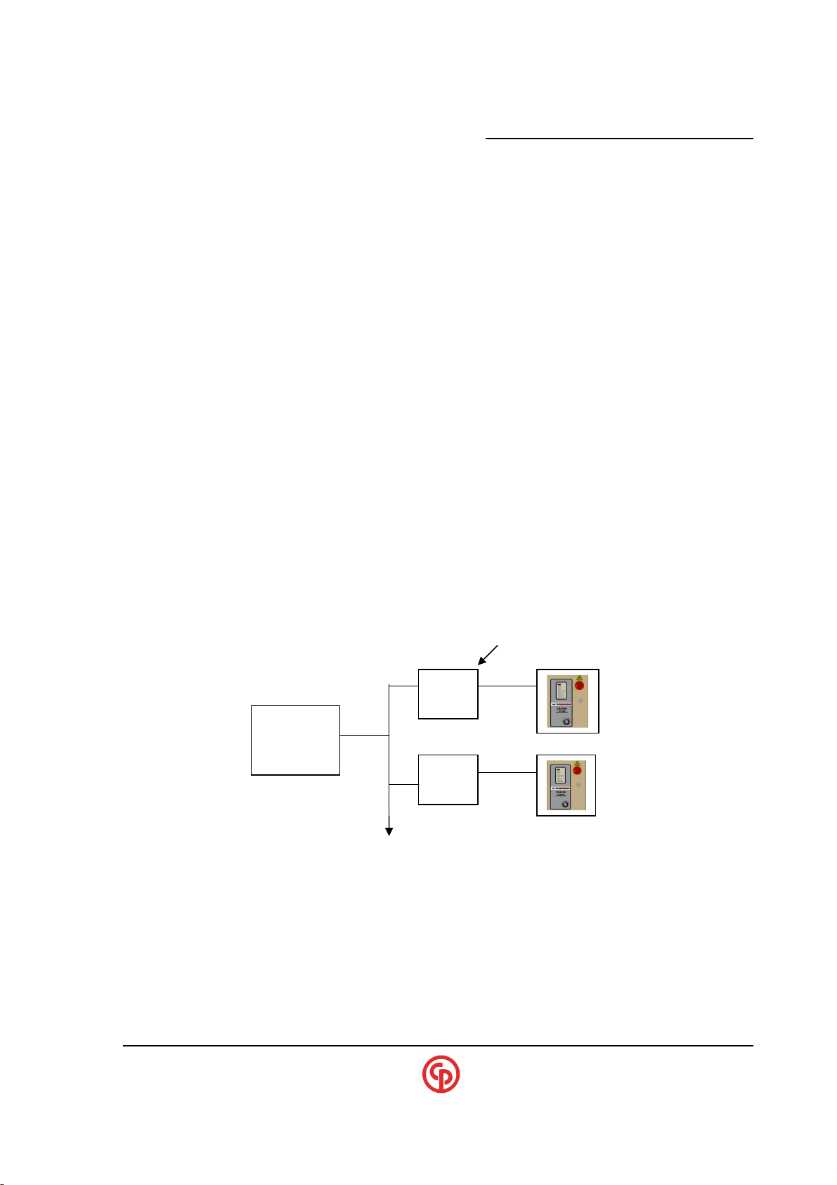
_____________________________________________________
CS4100/2100 Controllers Technical Reference
SPECIAL APPLICATION: FORD
The CS47XX has an Ethernet interface compliant with Ford specification PF3000.The basic steps to
setup a CS47XX controller for Ford follows:
Note that the CCM DipSwitch SW2 Swtich# 2 & 3 can force the FORD drivers without the console.
Also, units with the keypad/display can be used to setup most/all of the required settings.
1. Enable the FORD Ethernet interface via the RS-232 console.
2. Determine what IP address this controller must have, and enter it via the RS-232 console.
NOTE:
?
3 Either set defaults from the RS-232 console or via the keypad, or use the VS program to set up
the appropriate I/O sources. This must be done to provide proper functionality (Tool runs from
switches on tool, where are the psets selected etc.)
4 Set up the fastening strategy and setpoints either from the keypad or Visual Supervisor.
NOTE:
?
Example of a Ford based Network:
CEC box CS4700
Ford Server
The CS4700 Controller is considered the Ethernet “server” in
this configuration.
It may be necessary to assign a batch count that corresponds
with the pset number. (Example: Pset#1 has a batch of 1,
Pset#2 has a batch of 2, etc.)
Operator HMI (change psets/batch count etc.)
____________________________________________________________________________________________
September 2005 Page 51
Page 54

xxxxxxxxxx CS2700/4700 Controllers Technical Reference_________________________________________
SPECIAL APPLICATION: Screwdrivers
When setting up the CS2700 Controller for use with an SD25 Series screwdriver the VS Default
settings are used to map the I/O to fit typical screwdriver applications. A typical function times the
operation of the headlights to the Cycle Start mode of operation.
However, when it is set up for typical operation, the CS2700 Controller does not comply with GM
specifications. The I/O configuration mandated by GM Assembly does not match those that are
typically mapped for convenient screwdriver operation.
Here are the general setup instructions:
1. Enable the specific Ethernet interface via the RS-232 console (if applicable).
2. Set up the appropriate I/O fieldbus mapping via the RS-232 console.
Set defaults from the RS-232 console or via the keypad, OR VS to set up the appropriate I/O
sources. This must be done to provide the proper functionality (The tool runs from the switches
on tool, where are the psets selected etc.)
3. Set up the fastening strategy and setpoints either from the keypad or VS.
At the present time, CS2700 Screwdriver Controllers that have Ethernet capability do NOT support
SDLC networking (via the RS-485 port).
SPECIAL APPLICATION: Tubenut and Offset Tools
With the current revision of software, these applications may require VS to modify the I/O to operate
the Tool in the manner desired. Setting “Defaults” from the Keypad/Display or CCM console may
not provide the Final desired configuration for these tool types.
Tubenut and Offset Nutrunners
You may need to uncheck the left-hand tightening option from keypad-based default settings
____________________________________________________________________________________________
Page 52 39-30-43083
Page 55

_____________________________________________________
CONTROLLER TYPE
Symptom
Possible Solution
CS4700
/2700
Controller
CS2700
with Ethernet capability
Any controller with Fieldbus
INTEGER values
Order) setting.
CS4100/2100 Controllers Technical Reference
General Troubleshooting (Basic)
(Any configuration)
(Screwdriver controller)
(DeviceNet, Profibus etc.)
Data is ok except for FLOAT and
Tool Won’t run
Won’t communicate to VS on SDLC port If CS2700 is configured for Ethernet capability,
Controller won’t respond to INPUT
commands via Fieldbus (Cycle Enable,
Cycle Start etc.)
1. No tool detected scrolling message
* Suspect tool/ITI board
* Suspect TCM
2. Invalid Parameters scrolling message
* Hook up VS (run VsSetup & Correct)
3. No LIGHTS on TCM
* Verify circuit breaker/GFCI
* If TCM is Rev.K or higher, the fuse
on the TCM servo may be blown.
(Note: Prior to Rev. K, the display
might still light even if the Servo
fuse is blown).
4. TCM looks OK with READY light
* Suspect INPUTs mapping (Use VsSetup)
* If external cycle-on, suspect 24vdc source
* If unit has Ethernet capability, improper
Defaults may have been selected blocking
INPUT source.
the SDLC port WILL NOT work. See the
section “Connecting to Visual Supervisor” in this
manual.
It is critical to have selected the correct default
which will allow INPUTS to enter in via Fieldbus.
See this manual “Determining Input Sources”
and selecting Default#1 (Via Keypad or
Console) should then allow inputs from Filedbus
Possibly need to change the ENDIAN (Byte
____________________________________________________________________________________________
September 2005 Page 53
Page 56
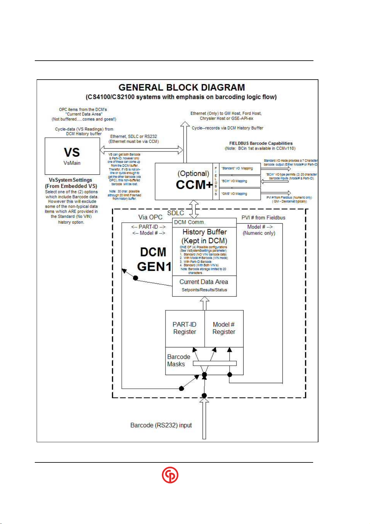
xxxxxxxxxx CS2700/4700 Controllers Technical Reference_________________________________________
General Block Diagram (Data/History/Barcodes)
____________________________________________________________________________________________
Page 54 39-30-43083
Page 57

www.cp.com
Please find your local contact at: www.cp.com
U.S. English
Printed in USA
Copyright 2005
CP techmotive, Novi, MI, USA
 Loading...