

Product Guide
VITP-MW3A
VitessePlus microwave presence detector
The VITP-MW3A microwave presence detector provides
automatic control of lighting loads via the VitessePlus
marshalling box.
The VITP-MW3A detects movement using a highly
sensitive microwave detector. This works by emitting low
power microwave signals and measuring the reflections as
the signals bounce off moving objects.
Functioning as a presence detector, the unit can turn lights
on when a room is occupied and off when the room is
empty. When used with a non-dimming LCM settings allow
lights to be turned off in response to ambient daylight. If a
dimming LCM is used the detector can be set-up to
implement a maintained illuminance (constant light)
system.
The VITP-MW3A has a unique adjustable sensor head that
allows the area of detection to be optimised for the
application.
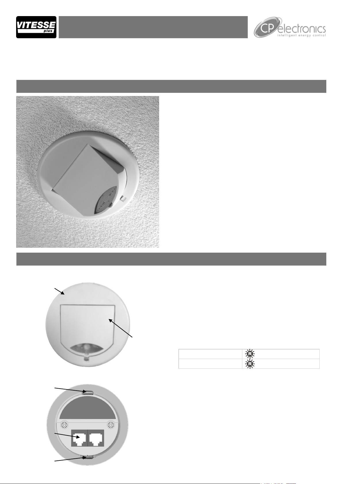
Overview
Front features
Mounting Bezel
Back features
Retaining Spring
Sensor Lens
which covers...
Microwave Sensor
IR Receiver
Light Level Sensor
Status LEDs
All functionality is fully programmable using an IR handset.
Features
Microwave Sensor
Detects movement within the unit’s detection range,
allowing load control in response to changes in occupancy.
IR Receiver
Receives control and programming commands from an
IR (infrared) handset.
Light Level Sensor
Measures the overall light level in the detection area
Status LEDs
The LED flashes Red to indicate the following:
Walk Test LED active
Valid setting received
RJ45 Connections
Two RJ45 connections for CAT5 patch leads.
when movement is detected
Two VitessePlus
RJ45 Connections
Retaining Spring
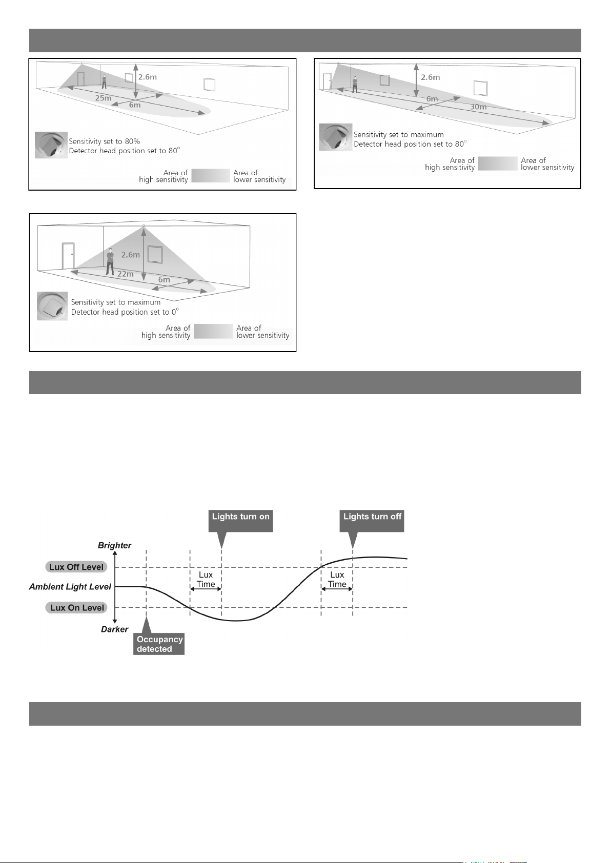
Detection diagrams
Ideal for large office or classroom
Ideal for open plan areas and offices
Ideal for corridor or aisle applications
Note. If the range is compromised by the ceiling construction /
material. Add the supplied 20mm spacer ring. See page 3 for
fitting details.
Sensor functionality
When movement is detected the detector sends a signal to the VitessePlus marshalling box (LCM). The LCM is
programmed to either, turn on the load (Presence) or the load is manuallly turned on via a switch (Absence). When the
area is no longer occupied the load will automatically switch off after an adjustable time period.
Sensitivity to movement of the microwave sensor can be adjusted using the Sensitivity parameter.
HINT: To assist in setting the Sensitivity, turn on the Walk Test LED which will flash red when movement is detected.
Switch Level On/Off (with non-dimming LCMs only)
Occupancy detection can be made dependant on the ambient light level using the Lux On Level and Lux Off Level
parameters. See page 7 for programming details.
Maintained Illuminance (with dimming LCMs only)
The detector measures the overall light level in the detection area and calculates the correct output for the luminaires, to
achieve a preset lux level (maintained illuminance).
Burn-in (with dimming LCMs only)
Overview
It is a requirement of many fluorescent lamp manufacturers to have the lamps on at maximum output for a period of time
to guarantee lamp life (refer to the manufacturer’s datasheet for details) As this VITP-MW3A is able to dim the lamps via
the VitessePlus LCM (lighting control module), the product provides a facility to disable this for a given period of time.
Operation
By setting the “Burn in” parameter, you can select a time during which the lamps are not allowed to deviate from
maximum output. The unit counts the time, and even remembers how long has elapsed in the event of a power failure.
To cancel the burn in function, simply select a time of 0. Note that when the lamps are changed, the burn in time should
be set again.
2
Choosing a Suitable Location
The VITP-MW3A is designed to be ceiling mounted and must satisfy the following criteria:
Avoid positioning the unit where direct sunlight may enter the sensor element.
Do not site the sensor within 1m of any lighting, forced air heating or ventilation.
Do not fix the sensor to an unstable or vibrating surface.
Avoid metallic objects directly in front of the sensor head.
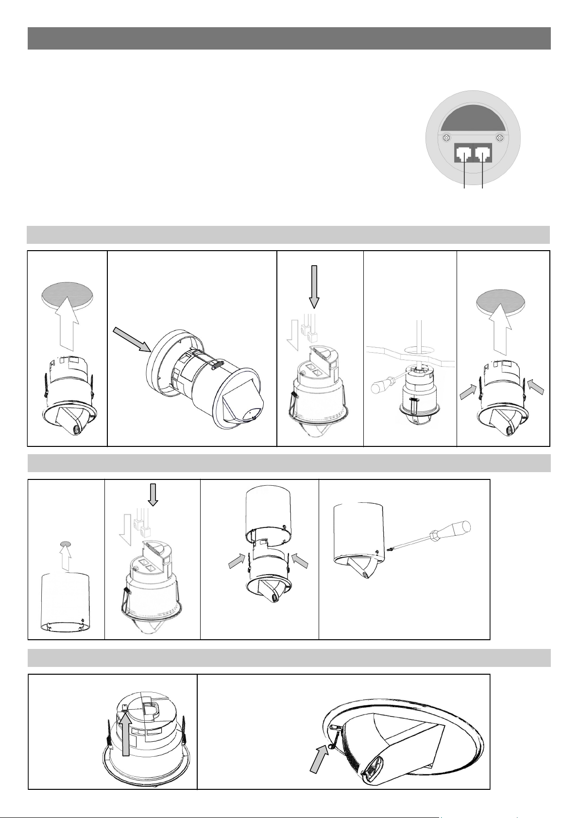
The VITP-MW3A is designed to be mounted using either:
Flush fixing, or
Surface fixing, using the optional Surface Mounting Box (part no. MWS3A-DBB).
Both methods are illustrated below.
Warning - be careful bending springs when mounting unit.
2 x VitessePlus RJ45 Connections
Flush fixing
Installation
for Cat 5 patch leads
1 5 4 3
Hole Ø74mm Attach cable clamp
2
If the range is compromised by the
ceiling construction / material. Add the
supplied 20mm spacer ring.
Surface fixing
1 3 2 4
Hole Ø30mm
MAX
Head locking
1 2
Remove metal
locking clip from
rear of unit.
Adjust head to
required position.
Push clip into position
shown below to lock
head.
To remove clip, lever
out with a small
screwdriver.
3

Power-up test procedure
When power is applied to the unit, the load will turn on immediately.
Set the timeout to 10 seconds (commissioning only) vacate the room or remain very still and wait for the load to switch
off .
Check that the load switches on when movement is detected.
Fault finding
What if the load does not turn ON?
Check to see if the Vitesse Plus marshalling box is powered up and the wiring is correct. Disconnect both RJ45
connections on the Cat 5 patch lead and re-connect, ensuring that they “click” into position, making good connection.
Check that the “lux hold off” setting is not keeping the lights off because there is sufficient ambient light.
If the detection range is smaller than expected, check the diagram above. Rotating the sensor slightly may improve
the range. If still reduced it may be compromised by the ceiling construction / material. Add the supplied 20mm
spacer ring. See page 3 for fitting details.
If the LED is flashing at regular intervals, this shows that the detector is being overridden. Press the cancel button on
the handset.
HINT: The Walk Test LED function can be used to check that the unit is detecting movement in the required area.
What if the load does not turn OFF?
Ensure that the area is left unoccupied for longer than the selected timer setting.
Make sure that the sensor is not adjacent to circulating air, heaters or lamps.
If the LED is flashing at regular intervals, this shows that the detector is being overridden on. Press the cancel button
on the handset.
Readback function (UNLCDHS handset only)
The UNLCDHS has the ability to read back the settings stored in a device.
To read back individual parameters
Navigate to the parameter and press the ‘R’ (Read) button whilst pointing at the device. The handset will click
when the parameter has been read back, the device will flash its LED, and the value will be shown against the
parameter in the menu.
To read back all of the parameters in a menu
Press and hold the ‘R’ (Read) button for more than 1 second.
The handset will click every time a parameter is received
The device will show multiple flashes of its LED
All of the values will be shown against the parameters in the menu.
The individual parameters may be edited and then saved as a ‘Macro’.
Notes
If a parameter(s) has been missed because of a communication error, the missing value(s) is replaced by dashes.
When reading back, the outputs of the LCM will temporarily be switched off, and will return to their normal state 2
seconds after the read back has been completed.
4

Basic programming - UHS5
The functionality of the VITP-MW3A is controlled by a number of parameters which can be
changed or programmed by any of the following devices:
UHS5 Infrared Handset. See below for programmable functions.
UNLCDHS Infrared Handset (with LCD). See user guide for full programming details.
For most basic programming operations the UHS5 handset can be used and the following procedures
are based on using this device.
Point the handset at the Sensor and send the required programming commands to the unit as shown
below.
Valid commands will be indicated by a red LED flash. See page 1 for details of other LED responses.
Note: other functions on the UHS5 which are not shown below are not applicable to this product.
Number of Shift key presses
Parameter
Name
Default
Value
0 1 2 3 UHS5 Handset Graphics Description
SHIFT 1 SHIFT 2 SHIFT 1 SHIFT 2
SHIFT 1 SHIFT 2
SHIFT 1 SHIFT 2
Button Activation
On / Raise On Raise Cancel
override
on
Off / Lower Off Lower Cancel
override
off
Walk test Off On Off
Time Out
(Time
adjustment)
Lux on
20 mins 1, 10 &
20
minutes
5, 15 &
30
minutes
10
seconds
9 2, 5 & 7 4, 6 & 9
level
(Switch
level on)
Light Level 6 (600) 2 (200)
5 (500)
7 (700)
Lux off
9 2, 5 & 7 4, 6 & 9
level
(Switch
level off)
Sensitivity 9 1, 5 & 9 3, 6 & 8
Defaults D
4 (400)
6 (600)
9 (900)
Turn lights on or to raise lights.
Turn lights off or to lower lights.
When set to On this causes a red LED to flash on
the sensor when it detects movement. Use this
feature to check for adequate sensitivity levels.
Once the detector is turned on, this value sets
how long the lights will stay on once movement
has ceased.
Lux level setting to prevent the luminaires being
switched on if the ambient light level is sufficient
(adjustable between 1
and 9). The luminaires will always be switched on
at level 9.
Sets a target light level to be maintained by the
lighting system.
Lux level setting to switch the luminaires off during
occupancy if the ambient light level goes above
the setting (adjustable between 1 and 9). Level 9
will always keep the lights on. This setting can be
used for “window row switching”.
Note: the Lux Off Level value must always be
greater than the Lux On Level value.
Sensitivity level for detecting movement.
1 = low sensitivity
9 = high sensitivity
Returns the unit to the default settings.
Burn-in 0 0 50 100
Shift
Determines how long the output will be at 100%
so that lamps ‘burn-in’. The ’burn-in’ time is not
affected by power supply interruptions.
Use this button to select the settings in red and
blue signified by the ‘Shift 1’ and ‘Shift 2’ LEDs
5

Advanced programming
Parameter Name Default Value Range / Options Description UHS5 UNLCDHS
Detector Parameters
Walk Test LED Off On or Off
Time Out
(Time adjustment)
Sensitivity On 9 1 (min) to 9 (max)
Sensitivity Off 9 1 (min) to 9 (max)
Lux time 0 0 (disabled)
Power Up State On On or Off
Factory default
User Modes
Raise
Lower
Override On
Override Off
Cancel
20 minutes 0-99 minutes
1-99 minutes
-
-
- -
- -
- -
- -
- -
When set to On this causes a red LED to flash on the sensor when it detects
movement. Use this feature to check for adequate sensitivity levels.
Once the detector is turned on, this value sets how long the lights will stay on once
movement has ceased. Select 0 for 10 second delay – use for commissioning only.
Sensitivity level for detecting movement when the detector is already on. *UHS5
sets Sensitivity On and Off to the same value.
Sensitivity level for detecting movement when the detector is off. *UHS5 sets
Sensitivity On and Off to the same value.
If the detector measures the lux level and decides that the output needs switching
on or off as a consequence, the lux time must elapse first. If at any time during the
timed delay the lux change reverses then the process is cancelled.
Select No for a 30 second delay on start up. If Yes is selected, there will be no
delay on start up and the detector will always power up detecting.
Restores factory default settings
Increase light level. Reverts when occupancy cycle complete.
Decrease light level. Reverts when occupancy cycle complete.
If the lights are off, sending the IR command will turn them on immediately and
revert to automatic operation using the manual timeout period.
If the lights are on, sending the IR command will turn them off immediately. After
the manual timeout period (described above), the sensor will revert to automatic.
Cancels the on or off override, returning the detector to normal operation.
*
*
6

Lux switching on all channels covered by one sensor (non-dimming LCMs only)
Lux on level
(Switch level on)
Lux off level
(Switch level off)
Lux switching on Channel A only (contact CP Electronics for LCM DIL switch settings)
9 1 to 9
9 1 to 9
For a higher resolution
a scale of 101-199 is
available (UNLCDHS
only)
For a higher resolution
a scale of 101-199 is
available (UNLCDHS
only)
Sets a minimum light level below which the microwave sensor is enabled, allowing
lights to be turned on by movement. The luminaires will always be switched on at
level 199 (maximum).
Note: the Lux Level Off value must always be greater than the Lux Level On value.
Sets a maximum light level above which the microwave sensor is disabled,
preventing lights from being turned on by movement. It is recommended that it is a
minimum of 10 levels higher than the Lux Level On value o avoid nuisance
switching.
Select ‘Standalone’
Select ‘DD’ product.
Select ‘Config’.
Select ‘Channel Mode’.
Select ‘Sw & Dim separate’ by pressing ’+’ or ’-’. Send setting to detector.
Go back to ‘Output Ch. 2’ menu.
Scroll down to ‘Light level’ appears with 3 figures (000 to 999 scale) next to it.
Type in a value or use the ’+’ or ’-’ keys. Send value to detector.
Re-adjust the light level if required to suit the lux switching level required and send value to detector.
Advanced programming
Dimming Functions (dimming LCMs only)
Light Level
(maintained illuminance)
Burn-in 0 0 (disabled) or
Speed On 40 Measured in 0.1
Speed Set 5 Measured in 0.1
Set Seconds 120 1 to 999 seconds
User Modes (dimming LCMs only)
Raise
Lower
Scene up
Scene down
Scene #
Override On
Override Off
Cancel
600 1 to 998 (999
disabled)
1 to 999 hours
sec intervals.
sec intervals.
- -
- -
- -
- -
- -
- -
- -
- -
Sets a target light level to be maintained by the lighting system.
Determines how long the output will be at 100% so that lamps ‘burn-in’. The ’burnin’ time is not affected by power supply interruptions.
Determines the dimming response speed after the setup time has finished.
Determines the dimming response speed during the set up time. Measured in 0.1
sec intervals. If set to 0 will disable dimming for “Set seconds” below, used if
fittings are required to warm up before dimming.
Determines how long the dimming response set-up period lasts on power-up or on
setting change. This enables the desired lux level to be achieved rapidly when the
lights come on, or during setup.
Increase light level. Reverts when occupancy cycle complete.
Decrease light level. Reverts when occupancy cycle complete.
Steps up between 6 pre-defined scenes.
Steps down between 6 pre-defined scenes.
Select the individual scene, between 0 and 6.
(1 = min. output; 2 = 10%; 3 = 25%; 4 = 50%; 5 = 75%; 6 = 100%)
If the lights are off, sending the IR command will turn them on immediately and
revert to automatic operation using the manual timeout period.
If the lights are on, sending the IR command will turn them off immediately. After
the manual timeout period (described above), the sensor will revert to automatic.
Cancels the on or off override, returning the detector to normal operation.
7

Technical data
Dimensions See diagrams opposite
Weight 0.1kg
Supply Voltage 12VDC
Power consumption On 447mW, Off 400mW
Temperature -10ºC to 50ºC
Humidity 5 to 95% non-condensing
Material (casing) Flame retardant ABS and PC/ABS
Type Class 2
IP rating IP40
Safety The microwave radiation emitted
by these units is extremely low
power and complies with ANSI
standard “IEEEC95.1-1999
Standard for Safety Levels with
Respect to Human Exposure to
Radio Frequency Electromagnetic
Fields 3kHz 300GHz.”
IP rating IP40
Compliance EMC-2004/108/EC
LVD-2006/95/EC
VITP-MW3A
MWS3A-DBB
Microwave frequency compatibility
The allowable frequency of operation of this product is different depending on region. Please select the correct order
code using the table below.
Suffix Region Frequency
blank UK, China, India, Middle East, Malaysia, Hong Kong, Singapore 10.687GHz
-R2 Australia and all of Europe except: UK, France, Portugal, Germany, Switzerland, Austria, Slovak Republic, Republic of Ireland 10.525GHz
-R3 France, Portugal, Switzerland 9.900GHz
-R4 Germany, Austria, Slovak Republic 9.350GHz
-R5 Republic of Ireland 10.41GHz
Part numbers
Part number Description
Detectors
Marshalling boxes
Accessories
IMPORTANT NOTICE!
This device should be installed by a qualified electrician in
accordance with the latest edition of the IEE Wiring
Regulations and any applicable Building Regulations.
FM 45789 EMS 534520
Due to our policy of continual product improvement CP Electronics reserves the right to alter the specification of this product without prior notice.
8
VITP-MW3A VitessePlus microwave presence detector
VITP-MB VitessePlus marshalling box (non-dimming)
VITP-MBDSI VitessePlus dimming marshalling box DSI (digital dimming)
VITP-MBD VitessePlus dimming marshalling box 1-10V (analogue dimming)
DBB Surface mounting box
UHS User handset with on/off override and lux up / lux down adjustment
UHS3 User handset with on/off override and cancel only
UHS3/2 User handset with off override and cancel only
UHS5 Programming IR handset
UNLCDHS Universal LCD IR handset
C.P. Electronics Ltd
Brent Crescent
London
NW10 7XR
United Kingdom
Tel: + 44 (0) 333 900 0671
Fax: + 44 (0) 333 900 0674
www.cpelectronics.co.uk
enquiry@cpelectronics.co.uk
Ref: #WD621 Issue 2
 Loading...