


Product Guide
VITM6
Vitesse Modular 6 - Dimming Modules
Overview
The Vitesse modular system is a cost effective method of providing power and control for lighting installations in industrial, commercial and retail buildings. The system is designed for ease of installation: mains input is connected using the spacious wiring compartment; control inputs and outputs are pluggable using industry standard connectors. The modular approach allows for between 4 and 16 luminaires to be connected. The VITM6 is for use with dimming luminaires. The VITM6-SELVMOD converter provides SELV switch inputs to allow digital dimming whilst also overcoming the requirements of the IEE 17th edition wiring regulations cost effectively.
|
|
|
|
|
|
|
|
|
System Components |
||
|
|
|
|
|
|
|
|
|
|
|
9 pole interface |
|
|
|
|
|
|
|
Fixing points |
|
|
|
connector and lead |
|
|
|
|
|
|
|
|
|
|
supplied with |
|
|
|
|
|
|
|
|
M6 (1/4”) |
|
|
|
|
|
|
|
|
|
202mm |
122mm |
|
|
detectors |
||
|
|
|
|
|
150mm |
|
75mm |
|
|
|
|
|
|
|
|
|
|
|
|
|
|
|
|
|
|
|
|
|
|
|
|
|
|
|
|
|
|
|
|
|
|
|
|
|
|
|
|
|
|
|
|
|
|
|
|
|
|
|
|
146mm |
127mm |
VITM6-S |
VITM6-E |
|
Vitesse modular starter for dimming systems |
Vitesse modular extender for dimming systems |
|
Height - allow 150mm for total height of unit (including connectors and cable) |
VITM6-SELVMOD |
|
|
|
Pluggable |
|
|
dimming switch |
|
|
module |
Installation
BESA box fixings |
Removable gland plate with |
|
3 x Ø20mm knockouts |
Channel for channel nuts (zebs)
3 x Ø20mm knockouts for rear cable entry
4 x key slots to accept M6 (1/4”)  fixings
Warning. This device works at mains voltage. Be sure to take care when working with electricity.
The box should be fixed on a smooth, flat surface or using drop rod fixings attached to channel nuts.
Ensure that there is easy access to the wiring compartment and all connectors once the box is in-situ.
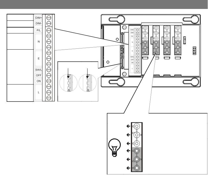
Wiring
Dim +
Dim -
Permanent Live
Neutral
Earth |
|
|
|
Large |
Small |
Switched live |
cables |
cables |
|
|
|
|
|
|
Off |
|
|
|
|
|
On |
|
|
Live
Cable clamps
All wiring should be mains rated.
Remove wiring compartment cover.
Wire the box using the diagrams opposite Permanent live feeds emergency fittings Off/On connects switches through to detectors Switched live turns the lights on and off
Use the cable clamps to secure the wiring or use cable glands (not supplied). The clamps can be split, and flipped over to clamp different cable diameters.
Replace wiring compartment cover.
Plug in the luminaires ensuring that the connector latches to the box.
2
Luminaire connections / Lead colours
Dim + |
Red |
Dim - |
White |
Permanent Live |
Black (6 core only) |
Neutral |
Blue |
Earth |
Green / Yellow |
Switched Live |
Brown |
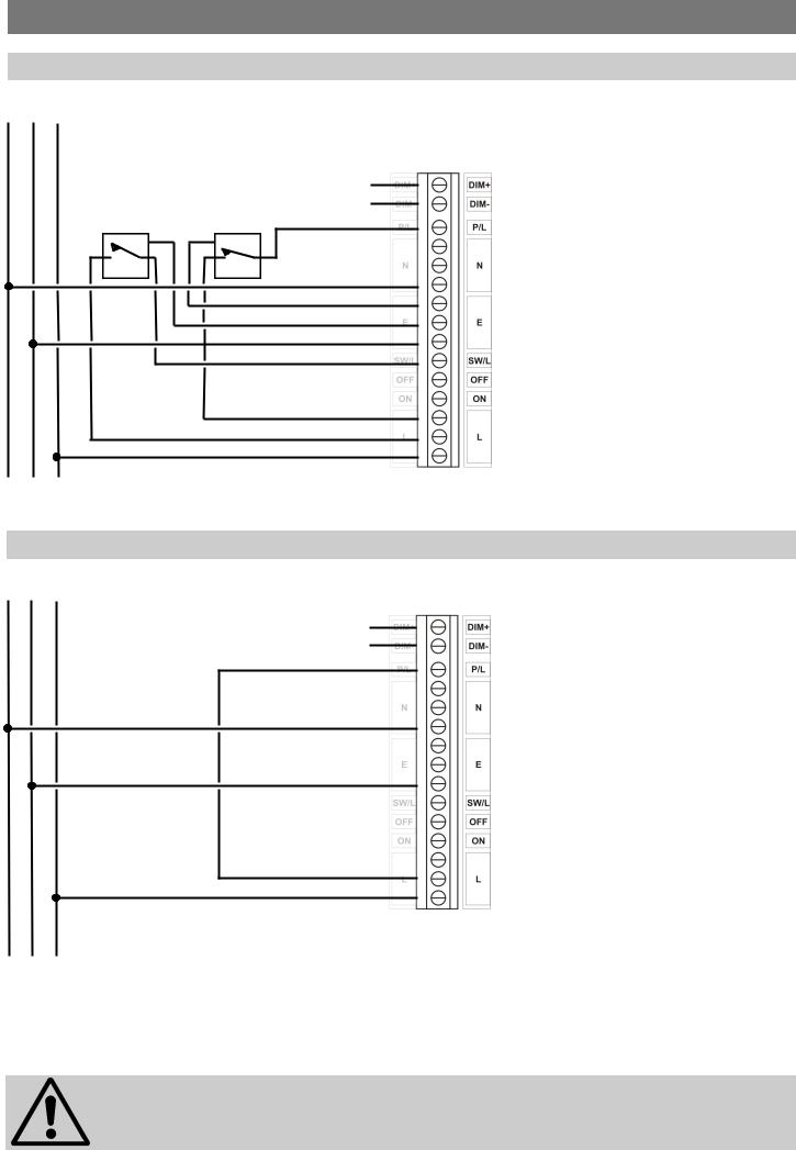
Wiring & Emergency Test
Local lighting switch and local emergency test switch
N |
E |
L |
|
|
|
|
Dimming input |
|
|
|
DALI / DSI / 1-10V |
|
|
Local lighting |
Local emergency test |
|
|
switch |
switch |
Emergency test using power interruption
N E L
Dimming input
DALI / DSI / 1-10V
Wire link
A local lighting switch may still be used when there is a central emergency test switch or when a circuit breaker is used to interrupt the power.
DO NOT WIRE ACROSS PHASES
3
 Loading...