


Product Guide
VITP-PD/IR
Dimming Ceiling Mounted Presence Detector
Contents
Section Contents Page
1 Dimensional information 1
2 Description and operation 2
3 Fixing and wiring 3
4 Programming 6
5
Detection pattern diagrams
6
Fault finding
7
Specification
8
Part numbers
1. Dimensions
11
11
12
12

2. Description & Operation
The VITP-PD/IR presence detector switches are designed to provide automatic control of lighting
loads via the VitessePlus marshalling box. They detect movement using a PIR sensor and turn the
load on. When an area is no longer occupied the load will switch off after an adjustable time out
period.
The detector also has an integral light sensor which can provide the following optional features:-
With VitessePlus dimming marshalling boxes, the unit can provide a maintained illuminance (or
daylight linking) feature. The internal light sensor measures the light level in an area and will
automatically adjust the output of the luminaries, via the marshalling box, to maintain a
constant, adjustable lux level. Please note that this function only works with VitessePlus
dimming marshalling boxes using either DSI or analogue (1-10V) dimming ballasts.
―Lux hold off‖ with non-dimming marshalling boxes, to prevent lighting coming on when a person
first enters the area if there is sufficient ambient light present (only available using the DDLCDHS programming handset - please see below).
―Lux switch off‖ with non-dimming marshalling boxes, to switch lighting off during occupancy if
the light level rises above a certain lux level in an area, which is sometimes required if ambient
light affects the area during certain times of the day (only available using the DD-LCDHS
programming handset - please see below).
When the unit is first powered up the PIR sensor will always detect immediately regardless of
whether the room is occupied or not.
An integral IR sensor in the unit allows the additional functions to be used in conjunction with
remote control handsets, there are several available:-
User Handset (Part No. UHS) the following functionality is available:-
Override the detector on or off (so lighting can stay on or off).
Act as a conventional dimmer - with dimming marshalling boxes only.
Change the maintained illuminance lux setting - with dimming marshalling boxes only.
User Handset 3 (Part No. UHS3) the following functionality is available:-
Override the detector on or off (so lighting can stay on or off) - no dimming override available.
User Handset 3/2 (Part No. UHS3/2) the following functionality is available:-
Override the detector off (so lighting can stay off) - no on override or dimming override available.
Programming Handset (Part No. DD-LCDHS) the following additional functionality is available for
commissioning purposes:-
Setting the time delay.
Sensitivity (range) adjustment.
Walk test LED - to check that the detector is picking up movement in the area.
Set the maintained illuminance lux setting on dimming marshalling boxes.
Set ―lux hold off‖ and ―lux switch off‖ levels on non-dimming marshalling boxes.
If remote control handsets are requested by the end user, it is usually recommended that the UHS
range or the UHS3 handset is supplied. The DD-LCDHS programming handset should only be used
by specifically trained personnel for commissioning purposes only.
2

3. Fixing & Wiring
1. Connect a Cat 5 (RJ45) patch lead from the back of the sensor to the relevant port on the
VitessePlus marshalling box. An additional RJ45 connector is provided to daisy chain
sensors together when being used with non-dimming marshalling boxes.
2. The detector should be sited so that the occupants of the room fall inside the detection pattern
shown in section 5, at a recommended ceiling height of 2.8m. Note that the lower the sensor is
installed the smaller the detection range will be, subject to the parameters shown on the
diagram.
3. Mount using one of the two options above overleaf.
4. On the side of the unit, use a small screwdriver to set the SENSITIVITY adjuster to maximum
(fully anticlockwise); the LUX level to maximum (fully anti-clockwise), and the TIME to
minimum (fully clockwise).
5. Power the unit up - the load should come on immediately.
6. Vacate the room or remain very still and wait for the load to switch off (this should take no
more than 2 minutes).
7. Check that the load switches on when movement is detected.
8. If required, adjust the sensitivity level down to reduce the range of detection.
9. For dimming applications the LUX adjuster determines the maintained illuminance level. When
the LUX is set to maximum (fully clockwise), maximum output will be seen from the dimming
ballasts. Adjust this down to get a lower output if required.
10. Select the time using the adjuster, fully anticlockwise is the maximum.
11. Using the UHS or UHS3 infra-red handset: the override on button turns the unit on
permanently; the override off button turns the unit off permanently; the cancel button cancels
the overrides. When an override is selected an LED will flash behind the lens inside the unit.
The UHS handset can also be used to set the lux levels - please refer to Section 4 (page 6) for
further details.
12. Using the DD-LCDHS programming handset; all the above parameters can be set - please
refer to Section 4 (page 7 and 8) for further details.
3

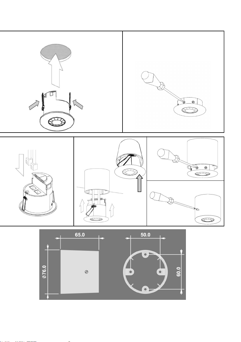
3. Fixing & Wiring (continued)
FLUSH FIXING
Warning - be careful bending
springs when mounting unit.
SURFACE FIXING
1 2
Hole Ø64mm
2 1
50mm or 60mm fixing centres
When mounting the detector:-
Avoid direct sunlight entering the sensor.
Do not site within 1m of forced air heating or ventilation.
Do not site within 1m of any lighting.
Do not fix to a vibrating surface.
4
Pull out spring tab and rotate
spring arm as shown
2 x VitessePlus RJ45 Connections
for Cat 5 patch leads
3
3
4
4
5
6
Surface Mount Backing Box
(Part No. DBB)
(not supplied with detector)
5

4. Programming
Using the User Handset (Part No. UHS)
USING AS A DIMMER
When the lighting is switched, the light level can be manually adjusted on a temporary
basis. Set the level using the LUX UP and LUX DOWN buttons.
To revert to maintained illuminance press the CANCEL button.
SETTING THE LUX LEVEL - DIMMING APPLICATIONS
The maintained illuminance target lux level can be set as above or using the handset.
To set the level press the SET button.
Then slowly press the LUX UP or LUX DOWN buttons repeatedly to obtain the
desired lux level.
After 2 minutes without pressing the buttons, the unit will revert to normal operation.
This can also be achieved sooner by pressing the CANCEL button.
SETTING THE SWITCH ON LEVEL - DIMMING APPLICATIONS
This is the light output that will be set when the unit first switches on.
Press the LUX UP and LUX DOWN buttons to reach the desired switch on level (do
not press the SET button first).
Press the ON button within 10 seconds to memorise the level as the switch on level.
OVERRIDING ON AND OFF
To turn off lighting permanently press the OFF button.
To return to automatic operation press the CANCEL button.
To turn on lighting permanently press the ON button.
To return to automatic operation press the CANCEL button.
In both override modes the red LED behind the detector lens will flash at regular
intervals to indicate that the detector has been overridden.
6

4. Programming (continued)
Using the Programming Handset (Part No. DD-LCDHS)
All the following functions can be programmed using the remote control DD-LCDHS
handset:
Please note that there are some parameters that appear on the DD-LCDHS handset
which are not listed below—do not attempt to use these.
Press the ―on‖ button on the handset to switch the handset on.
Select the menu using the left and right arrows and press ―on‖.
Adjustments to each parameter can be made by using the up and down arrow
keys on the handset.
To send the selected command press the ―on‖ button whilst pointing the handset
at the detector lens. The red LED behind the detector lens will flash to show that
the command has been received.
To exit the menu, scroll right until ―Previous menu‖ appears, then press ―on‖,
which will take you back to the main menu headers, or alternatively press and
hold the left key which will also take you back to the main menu headers.
To switch the handset off, press and hold the left arrow key. On the main menu
(―Detector Param‖ will show), scroll right until ―Off‖ appears . Press the ―on‖
button‖ to turn off. The handset will switch off automatically after a time period if
left on.
Time Delay, Sensitivity & Walk Test functions
1. Go to ―Detector Param‖ menu on the DD-LCDHS handset, and press ―on‖, then scroll
left and right using the left and right arrow keys through the menu to see the following
parameters.
(Factory default settings are shown in brackets):
1.1 Time mins (20 min) (Time delay adjustment) 10 seconds to 99 minutes time
delay (select 0 for 10 second delay – use for
commissioning only).
1.2 Sens On (9) Sensitivity level when the detector is already operational
- adjustable between 1 (min.) and 9 (max.)
1.3 Sens Off (9) Sensitivity level for switching the detector on
– adjustable between 1 (min.) and 9 (max.).
1.4 Walk Test (N) Select ―Y‖ for ―Yes‖ - to operate the function. An LED
behind the detector lens will flash to show movement is
being detected (use for commissioning only). Select ―N‖
for ―No‖ to cancel.
1.5 Factory Default Restores factory default settings.
7

4. Programming (continued)
Using the Programming Handset (Part No. DD-LCDHS)
Non-Dimming Lux Switching functions
2. Press and hold the left arrow key. On the main menu (―Detector Param‖ will be
showing), scroll right until the ―Ch1(sw) Set‖ menu appears on the DD-LCDHS
handset, and press ―on‖, then scroll left and right through the menu to see the
following parameters:
(Factory default settings are shown in brackets):
2.1 Switch level on (9) Lux level setting to prevent the luminaires being switched
on if the ambient light level is sufficient (adjustable
between 1 and 9). The luminaires will always be
switched on at level 9.
2.2 Switch level off (9) Lux level setting to switch the luminaires off during
occupancy if the ambient light level goes above the
setting (adjustable between 1 and 9). Level 9 will always
keep the lights on. This must be set higher than the
―Switch level on‖, and it is recommended that it is a
minimum of 2 levels higher than (2.1) to avoid nuisance
switching.
8

4. Programming (continued)
Using the Programming Handset (Part No. DD-LCDHS)
Dimming functions
3. Press and hold the left arrow key. On the main menu (―Detector Param‖ will be
showing), scroll right until the ―Ch2(dim) Set‖ menu appears on the DD-LCDHS
handset, and press ―on‖, then scroll left and right through the menu to see the
following parameters:
(Factory default settings are shown in brackets):
3.1 Light level (999) Maintained illuminance level (adjustable between 1 and
999). At 999 the output will be always be at maximum.
3.2 Off value (99) Always ensure that this is set to 99.
3.3 Speed on (40) Determines the dimming response speed after the setup
time has finished. Measured in 0.1 sec intervals.
3.4 Speed set (5) Determines the dimming response speed during the set up
time. Measured in 0.1 sec intervals.
3.5 Set seconds (120) Determines how long the dimming response set-up period
lasts on power-up or on setting change (adjustable between
1 and 999 seconds). This enables the desired lux level to be
achieved rapidly when the lights come on, or during setup.
Dimming functions are continued on Page 10
9

4. Programming (continued)
Using the Programming Handset (Part No. DD-LCDHS)
User menu functions with dimming applications
4. Press and hold the left arrow key. On the main menu (―Detector Param‖ will be
showing), scroll right until the ―User‖ menu appears on the DD-LCDHS handset, and
press ―select‖, then scroll left and right through the menu to see the following
parameters:
4.1 Lux up Increase light level. Reverts when occupancy cycle
complete.
4.2 Lux down Decrease light level. Reverts when occupancy cycle
complete.
4.3 Scene up Steps up between 6 pre-defined scenes.
4.4 Scene down Steps down between 6 pre-defined scenes.
4.5 Scene# Select the individual scene, between 0 and 6.
(1 = min. output; 2 = 10%; 3 = 25%; 4 = 50%; 5 = 75%; 6 =
100%)
4.6 Override on Permanently overrides the luminaire output on.
4.7 Override off Permanently overrides the luminaire output off.
4.8 Cancel Cancels the on or off override, returning the detector to
normal operation.
4.9 Set If sent before using Lux Up (5.1) or Lux Down (5.2), it will
set the maintained light level as in 4.1.
10
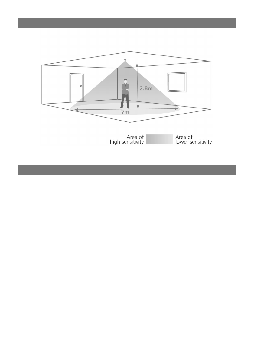
5. Detection Patterns
The above detection zone is available at maximum sensitivity.
If sensitivity is reduced, the range will also be reduced
6. Fault finding
LIGHTS DO NOT COME ON
Check to see if the Vitesse Plus
marshalling box is powered up and the
wiring is correct. Disconnect both
RJ45 connections on the Cat 5 patch
lead and re-connect, ensuring that
they ―click‖ into position, making good
connection.
Check that the ―lux hold off‖ setting is
not keeping the lights off because
there is sufficient ambient light.
If the detection range is smaller than
expected, check the diagram above.
Rotating the sensor slightly may
improve the range.
If the LED is flashing at regular
intervals, this shows that the detector
is being overridden. Press the cancel
button on the handset.
LIGHTS DO NOT GO OFF
Ensure that the area is left unoccupied
for longer than the selected timer
setting.
Make sure that the sensor is not
adjacent to circulating air, heaters or
lamps.
If the LED is flashing at regular
intervals, this shows that the detector
is being overridden on. Press the
cancel button on the handset.
11

7. Specification
LOAD
See datasheet for VitessePlus marshalling box
SUPPLY VOLTAGE 12VDC
TIME OUT PERIOD Adjustable 10 seconds to 99 minutes
LIGHT LEVEL Light to dark
FIXING METHOD Spring fixing, or surface fixing using additional Part No. DBB
(Surface mounting box)
MATERIAL Flame retardant ABS
TYPE Class 2
TEMPERATURE -10°C to 35°C
CONFORMITY EMC-89/336/EEC
LVD-73/23/EEC
8. Part Numbers
VITP-PD/IR VitessePlus presence detector with IR control (and dimming output)
DBB Surface mounting box
VITP-MB VitessePlus marshalling box (non-dimming)
VITP-MBDSI VitessePlus dimming marshalling box DSI (digital dimming)
VITP-MBD VitessePlus dimming marshalling box 1-10V (analogue dimming)
UHS User handset with on/off override and lux up / lux down adjustment
UHS3 User handset with on/off override and cancel only
UHS3/2 User handset with off override and cancel only
DD-LCDHS IR remote control programming handset with LCD screen
IMPORTANT NOTICE!
This device should be installed by a qualified electrician in
accordance with the latest edition of the IEE wiring regulations.
FM 45789 EMS 534520
Due to our policy of continual product improvement CP Electronics reserves the right
to alter the specification of this product without prior notice.
12
C.P. Electronics Ltd
Brent Crescent
London
NW10 7XR
United Kingdom
Tel: + 44 (0) 333 900 0671
Fax: + 44 (0) 333 900 0674
www.cpelectronics.co.uk
enquiry@cpelectronics.co.uk
Ref #WD157 Issue 5
 Loading...