

Product Guide
VITM4
Vitesse Modular 4 - Switching Modules
Overview
The Vitesse modular system is a cost effective method of providing power and control for lighting installations in industrial, commercial and retail buildings. The system is designed for ease of installation: mains input is connected using the
spacious wiring compartment; control inputs and outputs are pluggable using industry standard connectors. The modular
approach allows for between 4 and 16 luminaires to be connected. The VITM4 is for use with non-dimming luminaires.
The VITM4-SELVMOD converter provides a cost effective SELV switch input for overcoming the requirements of the IEE
17th edition wiring regulations.
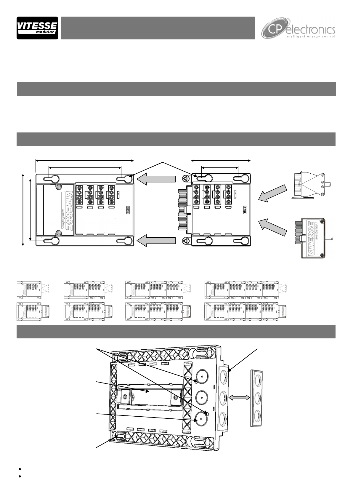
System Components
6 pole interface
connector and lead
supplied with
detectors
202mm
150mm
Fixing points
M6 (1/4”)
122mm
75mm
127mm
146mm
VITM4-S
Vitesse modular starter for non-dimming systems
Height - allow 150mm for total height of unit (including connectors and cable)
BESA box fixings
Channel for channel nuts (zebs)
VITM4-E
Vitesse modular extender for non-dimming systems
VITM4-SELVMOD
Pluggable SELV
switching module
Installation
Removable gland plate with
3 x Ø20mm knockouts
3 x Ø20mm knockouts for rear
cable entry
4 x key slots to accept M6 (1/4”)
fixings
Warning. This device works at mains voltage. Be sure to take care when working with electricity.
The box should be fixed on a smooth, flat surface or using drop rod fixings attached to channel nuts.
Ensure that there is easy access to the wiring compartment and all connectors once the box is in-situ.
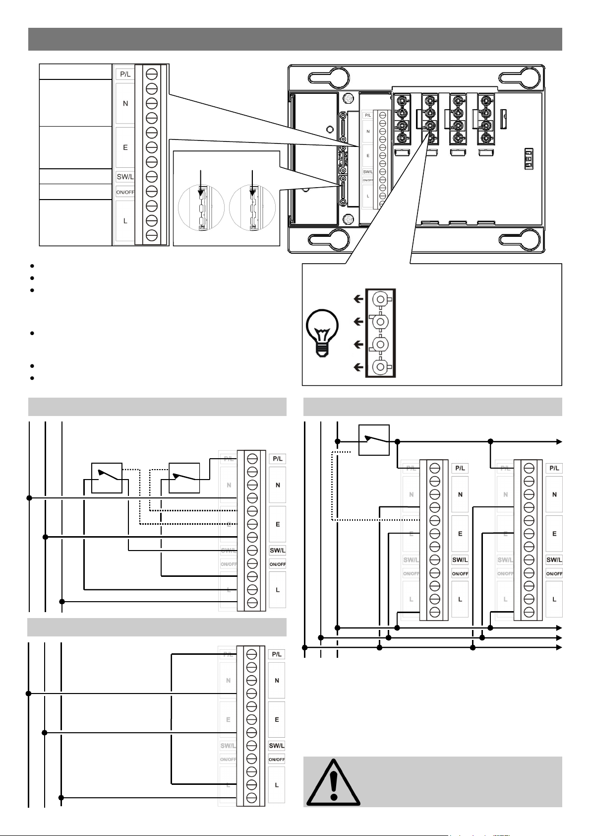
Wiring
Permanent Live
Neutral
Earth
Switched live
Absence detector
Live
Large
cables
Cable clamps
Small
cables
All wiring should be mains rated.
Remove wiring compartment cover.
Wire the box using the diagrams below
Permanent live feeds emergency fittings
Absence detector connects switches through to detectors
Switched live turns the lights on and off
Use the cable clamps to secure the wiring or use cable glands
(not supplied). The clamps can be split, and flipped over to
clamp different cable diameters.
Replace wiring compartment cover.
Plug in the luminaires ensuring that the connector latches to the
box.
Local lighting switch and local emergency test switch
N E L
Local lighting
switch
Local emergency test
switch
Luminaire connections / Lead colours
Permanent Live Black (4 core only)
Neutral Blue
Earth Green / Yellow
Switched Live Brown
Emergency test using central switch
N E L
Central
emergency
test switch
Multiple boxes
Emergency test using power interruption
N E L
Wire link
A local lighting switch may still be used when there
is a central emergency test switch or when a circuit
breaker is used to interrupt the power.
DO NOT WIRE ACROSS
PHASES
2

Presence detector connections
N E L
N E L
Automatic on, automatic off
Detector lead supplied with detector.
Where detectors connect to a single box a dual
lead is available VITM4-LD3-B.
Absence detector connections
Manual on, automatic off
Sensor
Detector lead supplied with detector.
Where detectors connect to a single box a dual
lead is available VITM4-LD3-PRM.
Sensor
VITM4-SELVMOD Switching Module
No mains voltage switch wires routed along walls removes the need for RCD protection under the IEE 17th Edition regulations.
The VITM4-SELVMOD module allows switches in parallel for 2-way and intermediate switching.
Optional time delay function.
The same switch can be used when multiple Vitesse Modular boxes are connected to different phases.
Time delay settings
Timer disabled
-
+
SELV switch connector
(observe polarity)
-
+
5 minutes
10 minutes
15 minutes
Low voltage (SELV) wiring
No requirement for:
Containment
RCDs
3
Momentary or latching switches
(momentary only—push and hold to
reset)

Ceiling rose / conduit box connection
Conduit box to VITM4-S mains wiring
Use a VITM-ROSE when there is a need to take power from a conduit box. Plug
the connector into the VITM-ROSE and wire the other end of the lead into the
terminals of the VITM4-S. A pre-wired version is available, VITM4-SL1.
Screw fixings to
conduit box
VITM-ROSE
Part numbers
Modules
VITM4-S 4 pole starter box
VITM4-E 4 pole extender box
VITM4-SL1 4 pole starter box with 1m lead
and ceiling rose connector
Dual Detector Leads (LSF)
VITM4-LD3-B 3m basic sensor lead
VITM4-LD3-PRM 3m premium sensor lead
VITM-ROSE mains wiring
Each pole accepts 1 x 4mm2 or 2 x 2.5mm2
Live supply
Earth
Neutral
Permanent
Live
VITM-ROSE connector wiring
Permanent Live
Neutral
Earth
Live supply
Presence / Absence Detectors
VITM4-EBDSPIR-B PIR presence detector
VITM4-EBDSPIR-PRM PIR presence/absence detector
VITM4-MWS3A-PRM Microwave presence/absence
detector (adjustable head)
VITM4-MWS6-PRM Microwave presence/absence
detector (fixed head)
VITM4-EBMPIR-B Miniature PIR presence detector
Luminaire Leads (LSF)
VITM4L303100W 3 core 3m 1.0mm2 White plug
VITM4L305100W 3 core 5m 1.0mm2 White plug
VITM4L403100R 4 core 3m 1.0mm2 Red plug
VITM4L405100R 4 core 5m 1.0mm2 Red plug
Other leads available to order.
VITM4-EBMPIR-PRM Miniature PIR premium presence
detector
Accessories
VITM4-SELVMOD SELV switching module
VITM-ROSE Ceiling rose module
Connectors
VITM4-LPW 4 pole luminaire plug white
VITM4-LPR 4 pole luminaire plug red
Ratings
Voltage 230VAC +/- 10%
Frequency 50Hz
Terminal capacity 4mm2 in wiring compartment
Temperature 0ºC to 35ºC
Power Rating of system 16A. Rating of each output 10A
Compliance BS 5733:1995
For lighting purposes only with suitable circuit protection. For fixed wiring only
IMPORTANT NOTICE!
This device should be installed by a
qualified electrician in accordance with
the latest edition of the IEE wiring
regulations.
FM 45789 EMS 534520
Due to our policy of continual product improvement CP Electronics reserves the right to alter the specification of this product without prior notice.
4
EU registered design no. 000638069-0003, 00638069-0004
Patent pending
C.P. Electronics Ltd
Brent Crescent
London
NW10 7XR
United Kingdom
Tel: + 44 (0) 333 900 0671
Fax: + 44 (0) 333 900 0674
www.cpelectronics.co.uk
enquiry@cpelectronics.co.uk
Ref: #WD289 Issue 2
 Loading...