

Product Guide
SPIR-F/C/IP
Ceiling Presence Detector IP55
The SPIR-F/C/IP presence detector switch is designed to provide automatic control
of lighting, heating or ventilation loads. They detect movement using a PIR sensor
and turn the load on. When an area is no longer occupied the load will switch off
after an adjustable time out period.
An adjustable internal light sensor provides additional energy saving in lighting
applications. When an area is occupied lighting is only switched on when the level
of natural light is below a preset level.
When the unit is first powered up the PIR sensor will always detect immediately
regardless of whether the room is occupied.
The /IP variant of these products is sealed to IP55 when used with the gasket provided.
Overview
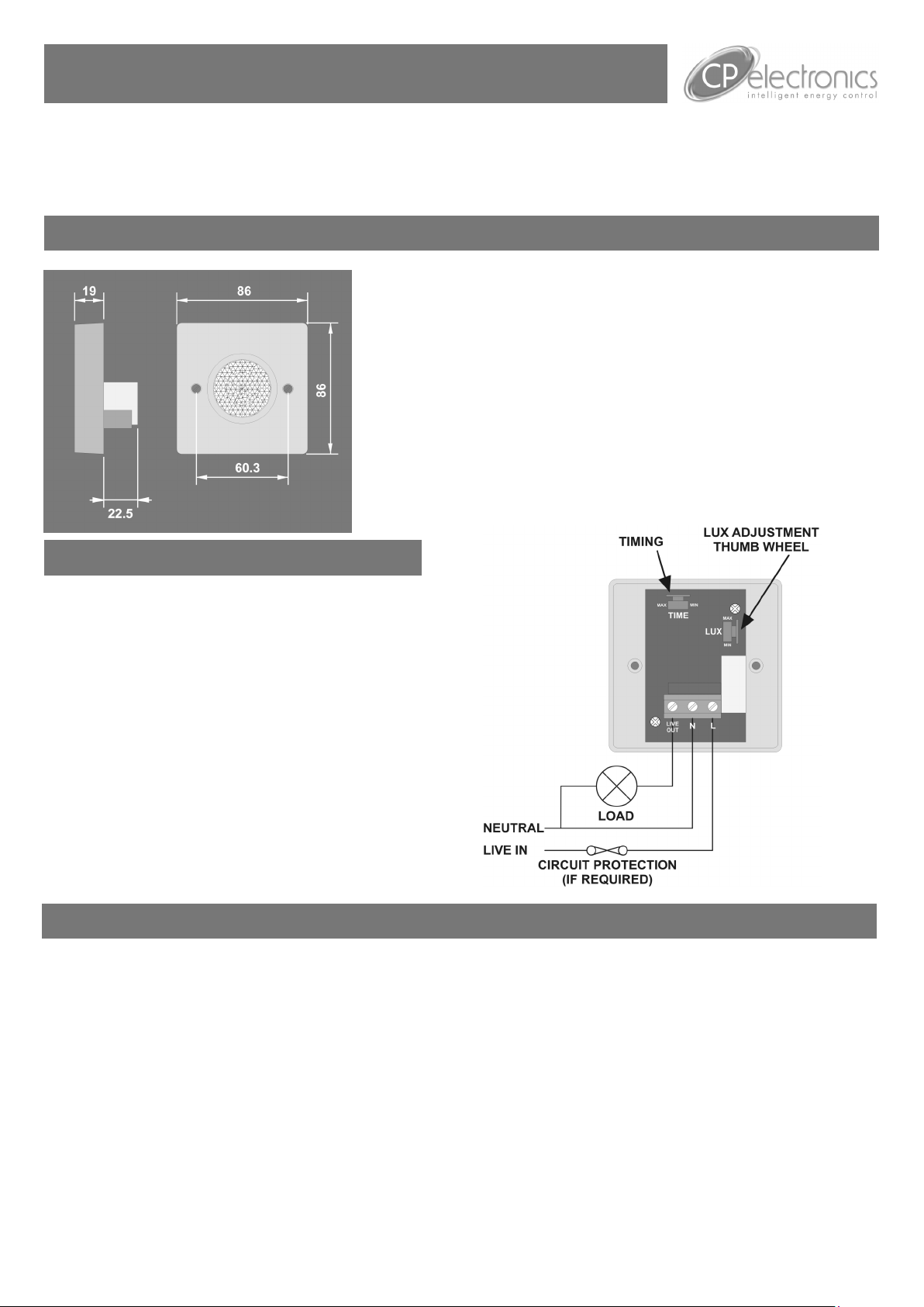
Wiring
Wire the SPIR-F/C products as in the diagram.
To switch from more than one position simply wire two or more units
in parallel to achieve two way and intermediate switching.
The detector should be sited so that the occupants of the room fall
inside the detection pattern shown overleaf, at a recommended
height of 3-4m on the ceiling. Note that the lower the sensor is installed the smaller the detection range will be, subject to the parameters shown on the diagram.
Avoid direct sunlight entering the sensor.
Do not site within 1m of forced air heating
or ventilation.
Do not site within 1m of any lighting.
Do not fix to a vibrating surface.
To maintain the IP rating the unit must not be used on ceilings with an
uneven surface.
Place the gasket (provided) between the unit and the ceiling.
The units is supplied with 2 washers to seal the screw holes.
Installation
Warning. This device works at mains potential. Be sure to take care when working with electricity.
1. Make sure the load is connected and in working order.
2. Isolate the mains supply to the circuit at the main consumer unit.
3. Connect the controller via the terminal block. Live supply to the L terminal, Neutral to the N terminal and the load to the LIVE OUT terminal.
4. Set the LUX level to maximum and the time to minimum.
5. Switch the mains supply back on at the distribution board.
6. The load should come on immediately.
7. Vacate the room or remain very still and wait for the load to switch off (should take no more than 2 minutes).
8. Check that the load switches on when movement is detected.
9. To set the final LUX level wait until the level of natural daylight is just enough that lighting is required. Starting with the LUX control fully clockwise (at minimum), very slowly turn the control anti-clockwise until the lights come on. Note that when the LUX control is at maximum then the
lights will always come on with occupancy.
10. Set the time required.
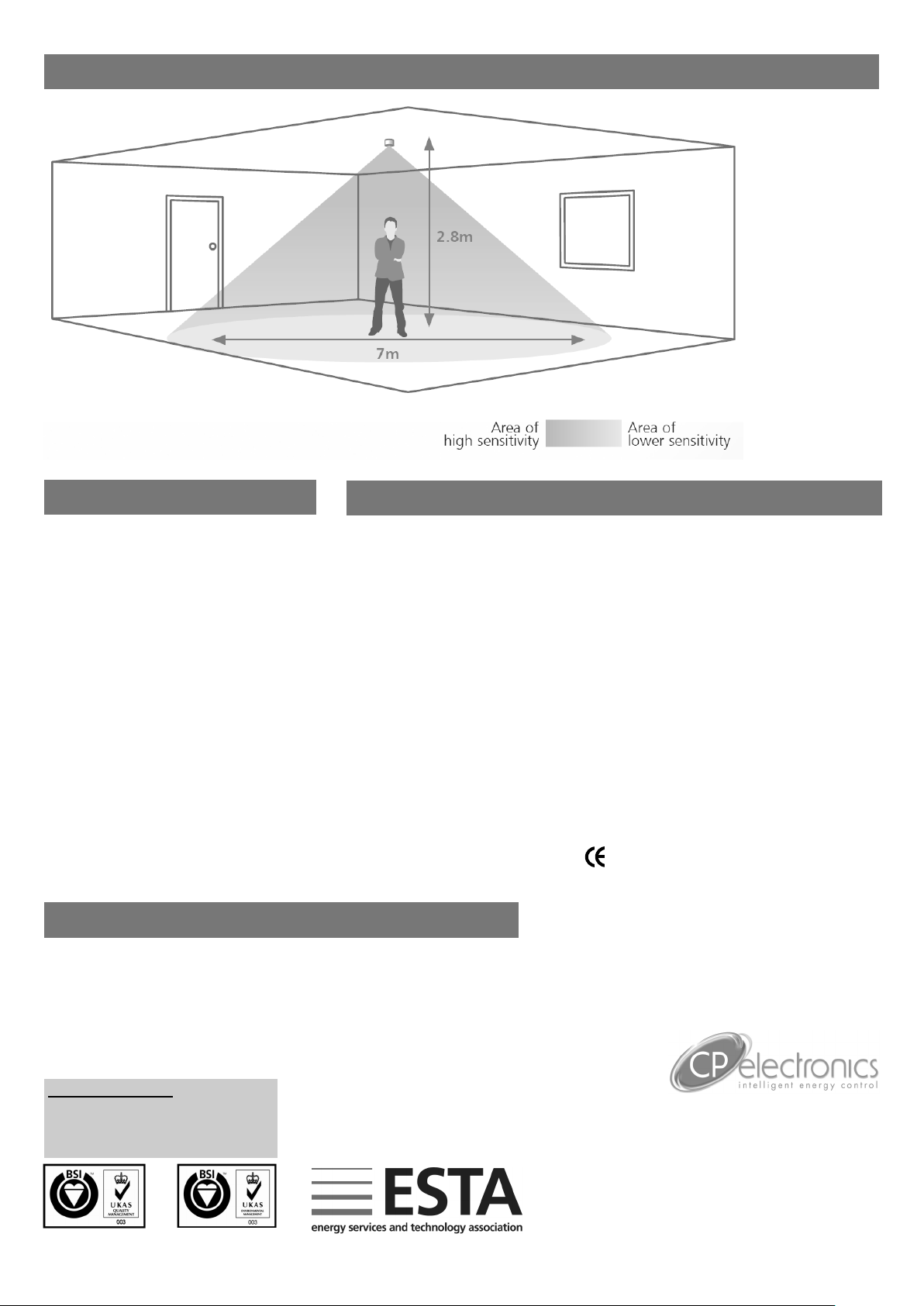
DETECTION PATTERN
FAULT FINDING
LOAD DOES NOT COME ON
Check to see if the live supply to the circuit is
good. Strap across the L and LIVE OUT terminal to turn the load on.
If the supply and wiring are good, check the
LUX level setting. Increase the LUX level setting to allow the controller to turn on at higher
ambient natural light level.
If the detection range is smaller than expected,
check the diagram above. Rotating the sensor
slightly may improve the range.
LIGHTS DO NOT GO OFF
Ensure that the area is left unoccupied for
longer than the selected timer setting.
Make sure that the sensor is not adjacent to
circulating air, heaters or lamps.
SPECIFICATION
LOAD
16 Amp resistive load
10 Amp incandescent lighting
6 Amp fluorescent lighting
3 Amp compact fluorescent lighting
3 Amp low energy lighting
3 Amp low voltage lighting (switch primary of transformer)
Fluorescent lighting (max 6 fittings recommended)
For fluorescent lighting total power factor correction capacitance must not exceed 40μF.
3 Amp fans and ventilation equipment
Switch SON lighting loads via a contactor
SUPPLY VOLTAGE 220-240 Volts AC 50 Hz
TIME OUT PERIOD Adjustable 10 seconds to 30 minutes
LIGHT LEVEL Light to dark.
FIXING METHOD Surface fixing 25mm deep plastic surface mount moulded box.
Flush fixing 25mm steel wall box or 32mm deep cavity wall box.
TERMINAL CAPACITY 4.0mm2
MATERIAL Flame retardant ABS
TYPE Class 2
IP RATING IP55
TEMPERATURE -10°C to 35°C
CONFORMITY EMC-89/336/EEC
LVD-73/23/EEC
PART NUMBERS
SPIR-F/C/IP Ceiling mounted presence detector c/w internal lux sensor
IMPORTANT NOTICE!
This device should be installed by a
qualified electrician in accordance with
the latest edition of the IEE wiring
regulations.
FM 45789 EMS 534520
Due to our policy of continual product improvement CP Electronics reserves the right to alter the specification of this product without prior notice.
C.P. Electronics Ltd
Brent Crescent
London
NW10 7XR
United Kingdom
Tel: + 44 (0) 333 900 0671
Fax: + 44 (0) 333 900 0674
www.cpelectronics.co.uk
enquiry@cpelectronics.co.uk
Ref #WD224 Issue 2
 Loading...