


PDS & PDS-OV
Product Guide
No Neutral Presence Detector
The PDS presence detection switch replaces a standard single gang light
switch. It detects movement using a PIR sensor and turns the lights on, (either
incandescent and fluorescent loads). An internal light sensor is provided for
additional energy saving. W hen an area is occupied lighting is only switched on
when the level of natural light is below a preset level. When an area is no longer
occupied the lights will switch off after an adjustable time out period.
The PDS-OV comes with a manual override facility for turning lights on and off
by simply pressing the lamp symbol in the bottom right hand corner of the front
plate.
If the lights are on, using the override will turn the lights off permanently until the
override is pressed again.
If the lights are off (because of the ambient light), use the override to turn the
lights on. The lights will remain on until the occupancy period is over.
Wire the PDS and PDS-OV as in the diagram.
To switch from more than one position simply wire two or more units
in parallel to achieve two way and intermediate switching.
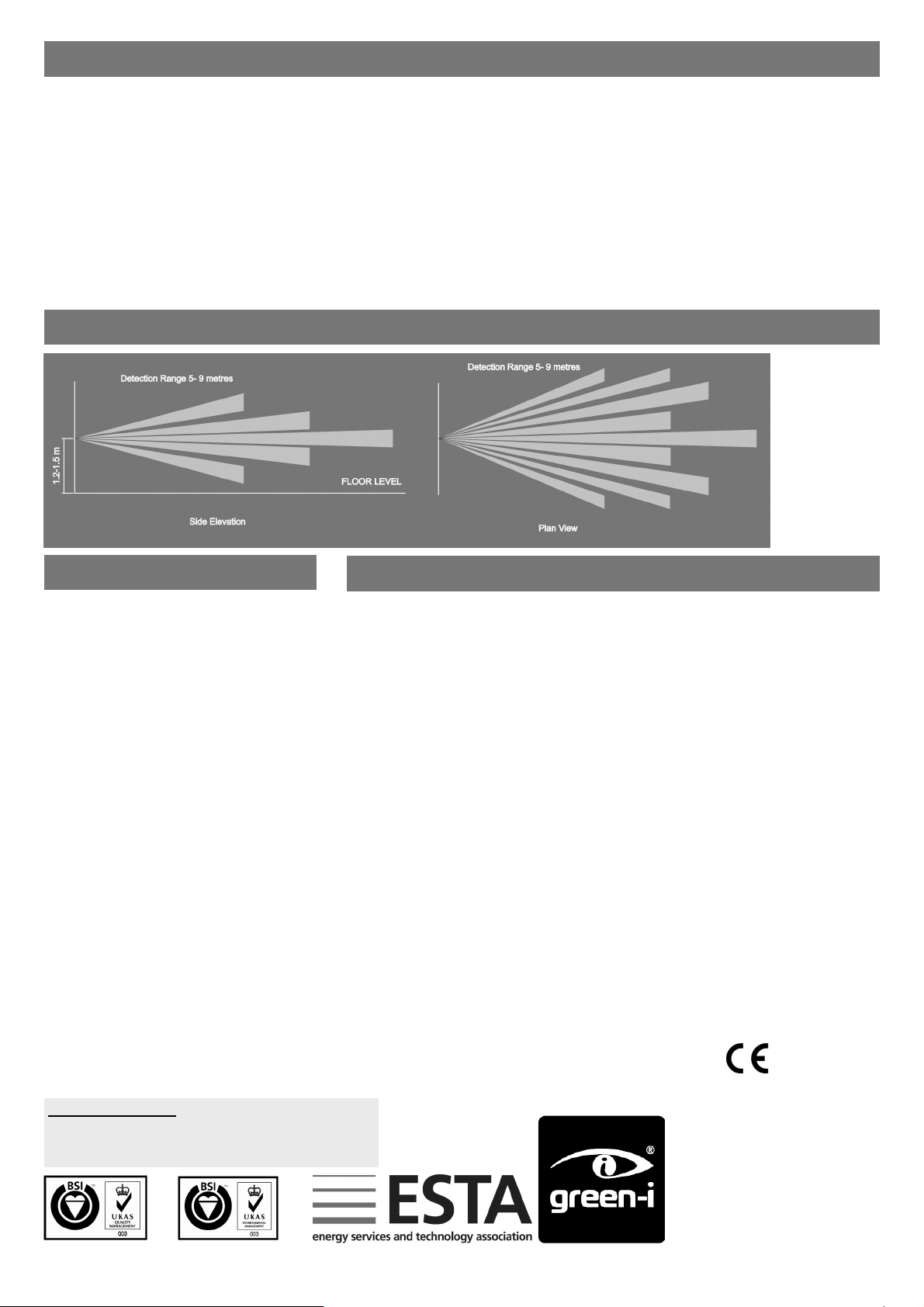
The detector should be sited so that the occupants of the room fall
inside the detection pattern shown overleaf, at a recommended
height of 1.2m to 1.5m. N ote that the higher the sensor is installed
the shorter the detection range will be.
Avoid direct sunlight entering the sensor.
Do not site within 1m of forced air heating
or ventilation.
Do not site within 1m of any lighting.
Do not fix to a vibrating surf ace.
Overview
Wiring
Warning. This device works at mains potential. Be sure to take care
when working with electricity.
1. Make sure the load is connected and in working order.
2. Isolate the mains supply to the circuit at the main consumer unit.
3. Connect the controller via the terminal block. Live supply to the L
terminal, and the load to the LIVE OUT terminal. DO NOT
SWITCH THE MAINS SUPPLY ON YET.
4. With the controller connected set the bottom switch, position 1, to
ON to power up the unit. A flashing LED should be visible
through the detector lens. If it is then the internal battery is
charged and you can proceed to step 6.
5. If not the battery requires charging. Change switch position 1 to
OFF, ensure that the mains supply and load are connected,
screw the unit to the wall, and switch the mains supply on . The
unit should be left for 24 hours to fully charge, after which go
back to step 4.
6. Set the LUX level thumbwheel fully clockwise, set the time out
period required using the switches according to the chart below.
Do this by moving switch positions 2, 3 & 4 only.
Installation
7. Screw the unit to the wall and switch the mains supply back on at
the distribution board. The LED behind the detector lens should
stop flashing after a few seconds. If it continues to flash there is
either no load on the circuit, a problem with the wiring, or the light
fitting needs a power factor correction capacitor (see specifica-
tion overleaf). Fix the problem, turn off switch 1 and start from
step 4.
8. After approximately 5 seconds from power up the load will turn
on and for the first 10 minutes of operating the controller has
a fixed time out period of 10 seconds to aid setting the LUX
level. After 10 minutes the time out reverts to the set value.
9. To set the LUX level wait until the level of natural daylight is just
enough that lighting is required. Starting with the LUX thumbwheel fully anti-clockwise. Very slowly turn the thumbwheel
clockwise until the lights come on. It is important that this is done
during the first 10 minutes of power up. If you miss this then
move switch 1 to OFF and then back to ON. Note that when the
LUX thumbwheel is fully clockwise then the lights will always
come on with occupancy.
See over for installing multiple sensors
Installation cont.
Installing multiple sensors
PDS
1. When using multiple sensors to control the same load it is important that each sensor is installed and set up separately.
2. Follow the installation instructions overleaf for the first sensor.
3. Disconnect either or both connections to the sensor (L or LIVE OUT) but do not change the switch settings.
4. Leaving the first sensor disconnected, connect the second sensor and start the installation procedure from step 1.
5. Leaving both the first and second sensor disconnected, start work on the third sensor etc. until all of the sensors are worki ng.
6. Finally re-connect all of the sensors.
PDS-OV
1. When using multiple PDS-OV sensors to control the same load it is important that each sensor is turned off before the next sensor is installed.
2. When the each sensor has been installed and is working, simply press the lamp symbol to turn the lights off.
3. After installation has finished, press the lamp symbol on each sensor again to turn the lights back on.
Detection Pattern
Fault Finding
LIGHTS DO NOT COME ON
For the PSD-OV model only, press the lamp
symbol to ensure that the controller has not
been switched off manually.
Check to see if the live supply to the circuit is
good. Strap across the L and LIVE OUT terminal to turn the load on.
If the supply and wiring are good, check the
LUX level setting. Increase the LUX level setting to allow the controller to turn on at higher
ambient natural light level.
If the load still fails to turn on follow step 5 of
the installation instructions to recharge the internal battery.
LIGHTS DO NOT GO OFF
Ensure that the area is left unoccupied for a
greater time period than the time out period set
using the switch.
Make sure that the sensor is not adjacent to
circulating air, heaters or lamps.
LIGHTS FLICKER
Ensure that there are sufficient power factor
correction capacitors fitted.
Specification
LOAD
10 Amp incandescent lighting
6 Amp fluorescent lighting
3 Amp compact fluorescent lighting
3 Amp low energy lighting
3 Amp low voltage lighting (switch primary of transformer)
Fluorescent lighting (max 6 fittings recommended)
Fluorescent and compact fluorescent fittings with “switch start” ballasts - 6 ballasts maximum.
Power factor correction capacitors must be fitted.
Most fluorescent fittings have power factor correction capacitors fitted. If they are not present
the unit may fail the installation procedure, in which case fit one capacitor per circuit with a
minimum value of 1μF for every PDS or PDS-OV installed. Note that it is not necessary to fit a
capacitor on every fitting.
For fluorescent lighting total power factor correction capacitance must not exceed 40μF.
Not suitable for switching contactors
Not suitable for SON lighting
Not suitable for heating or ventilation loads.
Please contact our sales department for a suitable alternative product.
SUPPLY VOLTAGE 220-240 Volts AC 50 Hz
TIME OUT PERIOD Adjustable 5 minutes to 60 minutes by DIP switch.
LIGHT LEVEL Adjustable by thumbwheel light to dark.
FIXING METHOD Surface fixing 25mm deep plastic surface mount moulded box.
Flush fixing 15mm steel wall box or 32mm deep cavity wall box.
TERMINAL CAPACITY 1.5mm2
MATERIAL Flame retardant ABS
TYPE Class 2
TEMPERATURE -10°C to 35°C
CONFORMITY EMC-2004/108/EC
LVD-2006/95/EC
IMPORTANT NOTICE!
This device should be installed by a qualified electrician in
accordance with the latest edition of the IEE W iring
Regulations and any applicable Building Regulations.
FM 45789 EMS 534520
Due to our policy of continual product improvement CP Electronics reserves the right to alter the specification of this product without prior notice.
C.P. Electronics Ltd
Brent Crescent
London
NW10 7XR
United Kingdom
Tel: + 44 (0) 333 900 0671
Fax: + 44 (0) 333 900 0674
www.green-iswitches.co.uk
enquiry@green-iswitches.co.uk
Ref: #WD119 Issue 5
 Loading...