

CP Electronics MWS3A-PRM-2CH User Manual
Product Guide
MWS3A-PRM-2CH, MWS3A-PRM-2CH-NC
Ceiling Microwave presence/absence detector 2 channel
Overview
The MWS3A-PRM-2CH Microwave presence detector
provides automatic control of lighting loads with optional
manual control. It detects movement using a highly
sensitive microwave detector. This works by emitting low
power microwave signals and measuring the reflections as
the signals bounce off moving objects.
The detector provides two independently controlled output
channels that can be used for a variety of applications.
Occupancy of two independent lighting circuits using a
single detector, e.g. for essential and non-essential
supplies.
Occupancy and lux control of one lighting circuit and just
occupancy control of a second circuit, e.g. where a row of
luminaries by a window is lux controlled whilst inner rows
are switched on occupancy only .
Occupancy and lux control of a lighting circuit and just
occupancy control of a ventilation circuit .
Occupancy on both lighting circuits, with separate lux
control on each circuit.
The unit has a unique adjustable sensor head that allows
the area of detection to be optimised for the application.
All functionality is fully programmable using an IR handset.
MWS3A-PRM-2CH Ceiling Microwave detector 2 channel
MWS3A-PRM-2CH-NC Ceiling Microwave detector 2 channel
normally closed
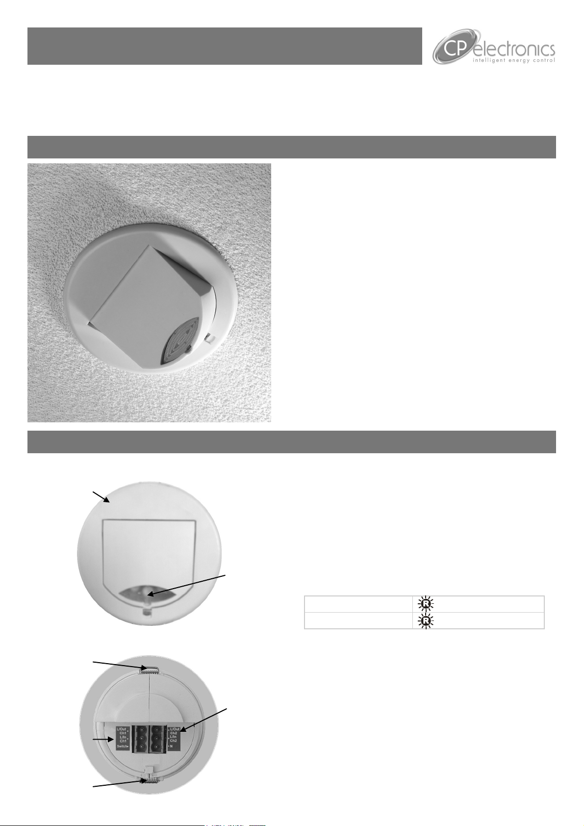
Front features
Mounting Bezel
Back features
Retaining Spring
Sensor Lens
which covers...
Microwave Sensor
IR Receiver
Light Level Sensor
Status LEDs
Channel 2
Connector
Features
Microwave Sensor
Detects movement within the unit’s detection range,
allowing load control in response to changes in occupancy.
IR Receiver
Receives control and programming commands from an
IR (infrared) handset.
Light Level Sensor
Measures the overall light level in the detection area
Status LEDs
The LED flashes Red to indicate the following:
Walk Test LED active
Valid setting received
Channel 1 Connector
Live input and output for Channel 1. Switch input
connection that can be used to manually override the lights
on or off.
Channel 2 Connector
Live input and output for Channel 2. Common Neutral
connection.
when movement is detected
Channel 1
Connector
Retaining Spring
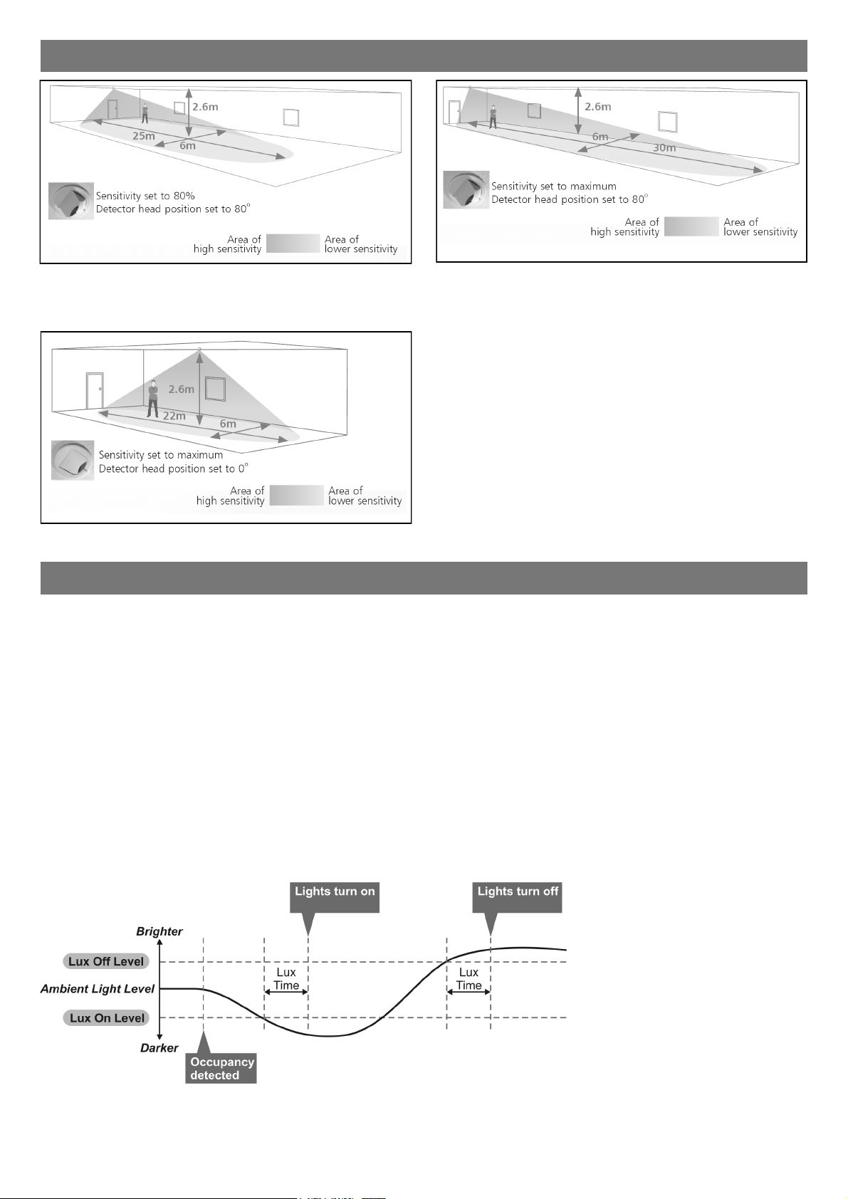
Detection diagram
Ideal for large office or classroom
Ideal for open plan areas and offices
Ideal for corridor or aisle applications
Note. If the range is compromised by the ceiling construction /
material. Add the supplied 20mm spacer ring. See page 4 for
fitting details.
Sensor functionality
Detection Mode
The Detection Mode can be set to behave in Presence or Absence mode:
Presence When movement is detected the load will automatically turn on. When the area is no longer occupied the
load will automatically switch off after an adjustable time period.
Absence The load is manually switched on. When the area is no longer occupied the load will automatically switch
off after the adjustable time period has elapsed.
In either case, sensitivity to movement of the Microwave sensor can be adjusted using the Sensitivity parameter.
HINT: To assist in setting the Sensitivity, turn on the Walk Test LED which will flash red when movement is detected.
Switch Level On/Off
Occupancy detection can be made dependant on the ambient light level using the Lux On Level and Lux Off Level
parameters.
The level can be set independently for each channel (UNLCDHS only). For example Channel 1 turns on with
occupancy whereas Channel 2 is held off by Lux.
Normally closed option
The MWS3A-PRM-2CH-NC provides a normally closed contact for fail safe operation. If the unit fails, the outputs will
default to on.
2
Installation
Choosing a Suitable Location
The detector should be sited so that the occupants of the room fall inside the detection pattern shown opposite).
Avoid positioning the unit where direct sunlight may enter the sensor element.
Do not site the sensor within 1m of any lighting, forced air heating or ventilation.
Do not fix the sensor to an unstable or vibrating surface.
Avoid metallic objects directly in front of the sensor head.
Note 1. When controlling two circuits, the circuits must be on the same phase.
2. L/In Ch1 is used to supply the detector with power.
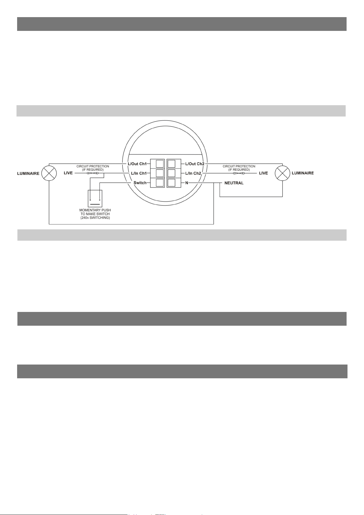
Wiring Diagram
CH1 and CH2 plugs are coded.
Ensure that the plugs are
inserted correctly and do not
apply excessive force
Absence detection
To use absence detection a retractive (momentary) switch must be connected between the 2 terminals on the
diagrams. Note that this will be switching mains voltage.
The unit ships with presence detection as default. To change to absence detection, press and release the
external switch 5 times within the first minute of power up. The LED will turn on solid for 30 seconds to indicate
absence mode has been selected.
To change back to presence detection, repeat the above procedure—the LED will flash for 30 seconds to indicate
presence mode has been selected.
Note: the above adjustments can also be made using the UHS5 or UNLCDHS handsets. See Programming sections.
Power-up test procedure
When power is applied to the unit, the load will turn on immediately.
Set the timeout to 10 seconds, vacate the room or remain very still and wait for the load to switch off .
Check that the load switches on when movement is detected.
The unit is now ready for programming.
Readback function (UNLCDHS handset only)
The UNLCDHS has the ability to read back the settings stored in a device.
To read back individual parameters
Navigate to the parameter and press the ‘R’ (Read) button whilst pointing at the device. The handset will click
when the parameter has been read back, the device will flash its LED, and the value will be shown against the
parameter in the menu.
To read back all of the parameters in a menu
Press and hold the ‘R’ (Read) button for more than 1 second.
The handset will click every time a parameter is received
The device will show multiple flashes of its LED
All of the values will be shown against the parameters in the menu.
The individual parameters may be edited and then saved as a ‘Macro’.
Notes
If a parameter(s) has been missed because of a communication error, the missing value(s) is replaced by dashes.
When reading back, the relay will temporarily be switched off, and will return to it’s normal state 2 seconds after
the read back has been completed.
3
 Loading...