

COX Live Axle Drive A16815G, Stockman 4500 Owner's Manual

READ THIS MANUAL BEFORE OPERATING MACHINE
DEATH, PERSONAL INJURY AND/OR PROPERTY DAMAGE MAY OCCUR UNLESS INSTRUCTIONS IN THIS MANUAL ARE FOLLOWED
NOTE: Bring this Manual when Service & or Warranty work is required.
RIDE-ON MOWER
OWNER/OPERATORS MANUAL
Model A16815G
Live Axle Drive
CS45L20B35-14.9Kw (20hp) Briggs & Stratton 890mm (35”) Cut
CS45L20B42-14.9Kw (20hp) Briggs & Stratton 1055mm (42”) Cut

OWNERS MANUAL FOR MODEL A16815G Live Drive rev 2 Page 2 1 February 2016
OWNERS INFORMATION
COX MODEL NO: _________________________________
COX INVENTORY CODE NO: ________________________
COX SERIAL NO:_______________________
Located on Label inside Transmission Housing
B&S ENGINE MODEL NO:______________TYPE:____________ CODE:_______________
Located on Engine refer Engine Owners Manual
DATE OF PURCHASE:__________________________________
OWNERS NAME:
ADDRESS:
TOWN/CITY:
STATE:
AUTHORISED COX DEALER/
DISTRIBUTOR:
ADDRESS:
TOWN/CITY:
STATE:
PRE DELIVERY CHECK LIST
Check parts Assemble Service Instruction
ALWAYS KEEP THIS MANUAL IN A SAFE PLACE.

OWNERS MANUAL FOR MODEL A16815G Live Drive rev 2 Page 3 1 February 2016
Read, understand, & follow all instructions in the
Owner/Operators manual.
Know the controls and how to stop the engine
quickly in an emergency.
Allow only responsible adults, who are familiar with
the instructions in this manual, to operate the machine.
Clear the area to be mowed of loose objects such as
sticks, stones, bones, wire, toys, debris, etc., which
could be picked up and thrown by the blades.
DO NOT mow whilst people, especially children, or
pets are in the mowing area.
DO NOT mow either direction on slopes beyond 15
degrees, (1 in 3.75), (27%).
Exercise extreme caution on slopes.
Reduce speed on slopes and in sharp turns to pre-
vent overturning or loss of control.
Start or stop slowly when on slopes.
Mow up and down slopes, not across the slope.
Stay alert for holes or bumps in the terrain and other
hidden hazards.
Use care when pulling loads-
a] Use only approved hitch point;
b] limit loads to those you can safely control;
c] Do not turn sharply;
d] use care when backing up.
Watch out for traffic when crossing or operating the
mower near roadways.
Stop the blades rotating before crossing surfaces
other than grass.
When using attachments, never direct discharge of
material toward bystanders nor allow anyone near
the machine while it is in operation.
Before leaving the operators position-
a] Disengage all clutches and secure cutting units;
b] Return drive pedal to neutral position and set the
parking brake;
c] Stop the engine and remove the key.
Disengage drive to attachments and stop engine-
a] Before refueling.
b] Before removing grass-catcher;
c] Before clearing blockages from chute;
d] Before checking, cleaning or working on the
mower;
e] After striking a foreign object (check the mower
for damage and make repairs before restarting and
operating the equipment);
f] If machine starts to vibrate abnormally (check immediately).
Disengage drive to attachments when transporting or
not in use.
A mower operator should be in good physical and
mental health and not under the influence of alcohol
or any drug which might impair vision, co-ordination
or judgment.
Never mow while barefoot or wearing open sandals
or thongs. Wear long trousers and heavy shoes.
It is advisable to wear suitable eye protection when
operating a mower.
Mow only in daylight or good artificial light.
Before using, always visually inspect to see that
blades, bolts and cutter assembly are not worn or
damaged. Replace worn or damaged blades and
bolts in sets to preserve balance.
Check all nuts, bolts, and screws often; always be
sure the mower is in safe operating condition.
Keep safety devices (guards and switches) in place
and in working order.
Never use the mower unless the grass catcher, or
guards provided by the manufacturer, are in position.
Ensure any replacement parts used comply with the
original manufacture’s recommendations and specifi-
cations.
Replace worn or faulty silencers.
Keep machine free of grass, leaves or other debris,
excessive oil, grease, or spilt fuel. These can be a
fire hazard.
Refuel outdoors only. Do not smoke while fueling
engine. Never remove the cap of the fuel tank or add
petrol while the engine is running or the engine is
hot. Remove fuel cap slowly to relieve any tank pressure. If fuel is spilled, do not attempt to start the
engine but move machine away from the area of the
spill and avoid creating any source of ignition until
fuel vapors have dissipated.
Check for fuel leaks while refueling, before and while
using the mower. If a fuel leak is found, do not start
or run the engine until the fuel leak is fixed and
spilled fuel is wiped away.
Do not operate engine in a confined space where
exhaust fumes (carbon monoxide) can collect.
Always mount the mower from the left or the oppo-
site side to the discharge chute.
Start the engine carefully with the cutting means dis-
engaged.
Do not over-speed the engine or alter governor set-
tings. Excessive speed is dangerous and shortens
mower life.
Stop the engine whenever you leave the mower,
even for a moment.
Store the mower in a well-ventilated room away from
naked flames such as may be found in hot water
heaters.
Do not lend or sell the mower, without the owners/
operators Manual.
SAFETY INSTRUCTIONS

OWNERS MANUAL FOR MODEL A16815G Live Drive rev 2 Page 4 1 February 2016
INTRODUCTION
THANK YOU, for purchasing a COX Live Drive, STOCKMAN 4500 Ride-on Mower.
Proudly Manufactured by Cox Industries (Australia) Pty. Ltd..
GENERAL SAFETY INSTRUCTIONS
READ THIS MANUAL carefully to
learn how to operate safely and
maintain your Ride-on Mower
effectively.
Failure to follow Safety, Operating
or Maintenance instructions in this
manual could result in
Death, P e r s o nal In j u r y or
Equipment Damage.
THIS MANUAL IS PART OF
YOUR RIDE-ON MOWER and
should be supplied with this Rideon Mower if you lend or sell this
Ride-on Mower. This should also
apply to the Engine Owners
Manual.
CONVENTIONS
Measurements in this manual are
given in metric units unless
otherwise stated.
Right-hand and Left- hand, are
determined by facing the direction
of forward travel.
Direction of rotation is determined
by looking into the components in
motion parallel to the axis of
rotation.
W R I T E P R O D U C T
IDENTIFICATION NUMBERS in
the Owners Information Section of
this manual. Accurately recording
these numbers will assist your Cox
Dealer when ordering spare parts
or help in tracing the Ride-on
Mower if it should be stolen. Store
this manual in a secure place
remote from the Ride-on Mower.
ENSURE YOU UNDERSTAND
THE WARRANTY POLICY with
regard to the responsibilities of
op erati o n, m a inten a nce and
ownership of this COX STOCKMAN
Ride-on Mower.
THE INTENDED USE OF THIS
RID E -O N M O W E R i s for
customary mowing of Landscaped
Parks, Gardens, Grounds, Sporting
Fields, Road Verges, Golf Course
Fairways, Orchards, Plantations,
and Vineyards.
Strict adherence to the conditions
of Operation, Maintenance, Service
& Repair as specified by the
manufacturer constitute essential
elements for The Intended Use.
Use in any other way not
specifically approved directly in
righting by the manufacturer is
considered as contrary to the
intended use and will increase the
risk of personal injury or property
da m ag e an d i s t h er e f o re
considered as misuse for which the
m a n u f a c t u r e r a c c e p t s n o
responsibility as these increased
risks must be accepted solely by
the user.
Do Not Modify the Machine
without direct specific approval by
the manufacturer as modification is
co n sider ed c o ntrar y to the
intended use and will increase the
risk of personal injury or property
da m ag e an d i s t h er e f o re
considered as misuse for which the
m a n u f a c t u r e r a c c e p t s n o
responsibility as these increased
risks must be accepted solely by
the user.
OPERATION, MAINTENANCE,
SERVICE AND REPAIR of this
Ride - o n M ower s h o uld b e
performed only by persons familiar
wi th its ch arac teristic s and
acquainted with the relevant
Safety, Operating and maintenance
instructions in this manual, as well
as a l l r e l e va n t S t a tu t o r y
Regulations in force at the place
and time.
When your Ride-on Mower needs
service or repair please remember
your Cox Dealer is an industry
trained professional who is
supported by the personnel of the
Sales and Marketing, Engineering,
Production, Procurement, Parts
Distribution, & Service Sections of
the Manufacturer and is dedicated
to your satisfaction.
THE INFORMATION INCLUDED
IN TH I S M AN U AL w as
considered correct at the time of
app r o val f o r p ri n t i n g . Cox
Industries (Australia) Pty Ltd
reserves the right to change
specifications or designs without
notice or obligation.
Training
Read, understand and follow all
instructions in the Ride-on Mower and
Engine Owner’s/Operator’s Manual as
well as on Machine Safety Signs.
Keep up to date with and follow
all relevant statuary regulations in
force at the place and time with
regard to ownership, transport,
operation, maintenance, service, and
repair, disposal or sale of this
machine.
Know the controls and the
proper use of the Equipment as
well as how to stop the Mowing
Attachment, Machine Travel, and
the Engine in an emergency.
All operators or users should
seek and obtain professional
and practical instruction.
Such instruction should emphasize:
The need for concentration when
working with ride-on machines.
Control of a ride-on machine
sliding on a slope will not be
regained by application of the
brake.
The main reasons for loss of
control are:
i) Insufficient wheel grip;
ii) Being driven to fast;
iii) Inadequate braking;
iv) The type of machine is
unsuitable for the task;
v) Lack of awareness of the
effect of ground conditions,
especially slopes;
vi) Incorrect hitching and load
distribution.
Never allow children or people
unfamiliar with these instructions
to operate the Ride-on Mower.
Never carry passengers.
Never mow while people,
especially children, or unrestrained
animals are nearby.
Keep in mind that the operator or
user is responsible for accidents or
hazards occurring to other people
or their property caused by this
machine.

OWNERS MANUAL FOR MODEL A16815G Live Drive rev 2 Page 5 1 February 2016
Preparation
While operating, always wear
substantial footwear (not open
sandals) and long trousers.
Thoroughly inspect the area
where the equipment is to be used
and remove all objects which can
be thrown by the machine.
WARNING – Petrol is highly
flammable:
i) Store f uel i n container s
specifically designed for this
purpose;
ii) Refuel outdoors only;
iii) Do not smoke while refuelling;
iv) Add fuel before starting the
engine;
v) Never remove the cap of the
fuel tank or add petrol while
the engine is running or when
the engine is hot;
vi) If petrol is spilled, do not
attempt to start the engine but
move the machine away from
the area of spillage and avoid
creating any source of ignition
until petrol vapours have
dissipated;
vii) Replace all fuel tank caps and
container caps securely.
Replace faulty Mufflers.
Before using, always visually
inspect to see that the cutter
assembly, blades, and blade bolts
are not worn or damaged.
Replace worn or damaged
blades and bolts in sets to
preserve balance.
Take care rotating one blade
by hand as this can cause other
blades to rotate.
Operation
Do not operate the engine in a
confined space where dangerous
carbon monoxide fumes can
collect.
Operate the machine only in
daylight or in good artificial light.
Before attempting to start the
engine, disengage Power take off
Clutch and depress clutch/brake
ped a l t o en s u re dr i v e i s
disengaged to the transmission.
Do not use on slopes of more
than 15 degrees (1 in 3.75 or
27%).
There is no such thing as a
safe slope.
Travel on grass slopes requires
particular care.
To guard against overturning:
i) Do not stop or start suddenly
when going up or downhill;
ii) Engage hydrostatic dr ive
slowly;
iii) Always keep hydrostatic drive
operating, especially when
travelling downhill;
iv) Machine speeds should be
kept low on slopes and during
tight turns;
v) Stay alert for humps and
hollows and other hidden
hazards;
vi) Never mow across the face of
the slope.
Use care when pulling loads or
using heavy equipment:
i) Use only approved hitch
points;
ii) Limit loads to those you can
safely control;
iii) Do not turn sharply;
iv) Use care when reversing;
Watch out for traffic when
crossing or near roadways.
Stop the blades rotating before
crossing surfaces other than grass.
When using the mowing
attac h m e n t , never d i r e c t
discharge of material towards
bystanders nor allow anyone else
near the machine while it is
operating.
Never operate the machine
with defective guards, or
without all safety devices in place
and operating correctly.
Do not change the engine
governor settings or over speed
the engine as excessive engine
speed can increase the risk of
personal injury.
Before leaving the operators
position:
i) Disengage the power take off
clutch:
ii) Set the parking brake in the
locked position.
D i s e n g a g e d r i v e t o
attachments when transporting,
emptying the catcher, or not in
use.
D i s e n g a g e d r i v e t o
attachments and stop engine
before refuelling.
D i s e n g a g e d r i v e t o
attachments, stop engine, and
remove the ignition key:
i) Before leaving the machine
unattended;
ii) Before clearing blockages or
unclogging the chute;
iii) After striking a foreign object.
(Inspect the machine for
damage and make repairs
before restarting or operating
the damaged equipment);
iv) If the machine starts to vibrate
a b n o r m a l l y . ( C h e c k
immediately).
D i s e n g a g e d r i v e t o
attachments, stop engine,
remove the ignition key, and
disconnect the spark plug
wires and battery positive lead
before working on, maintaining, or
servicing the machine.
S e c u r e t h e m o w i n g
attachment in the full up
position:
i) Before clearing blockages or
unclogging the chute;
ii) Before replacing the blades, or
adjusting the tension of the
blade bolts;
iii) Before placing any tools or any
part of your person under the
mowing attachment.
Turn the fuel off using the fuel
shut off valve at the conclusion
of operation.
Maintenance and
Storage
Keep all nuts, bolts and screws
tight to ensure the equipment is
in safe working order.
Replace worn or damaged
parts for safety.
Reduce the fire hazard, by
keeping the engine, muffler,
hydrostatic transaxle, battery
compartment, and petrol storage
area clear of grass, leaves, or
excessive oil and grease.
Also ensure the mowing
attachment drive belt can not
come into contact with grass,
sticks, and leaves built up on the
top surface of the mowing
attachment.
If the fuel tank has to be
drained this should be done out
outdoors.
Never store the machine with
petrol in the tank inside a
building where fumes can reach an
open flame or spark.
Allow the engine to cool before
storing the Ride-on Mower in any
enclosure.
When the machine is to be
pa r k e d , stored o r left
unattended raise the mowing
attachment and secure it in the full
up position.
GENERAL SAFETY INSTRUCTIONS CONT.

OWNERS MANUAL FOR MODEL A16815G Live Drive rev 2 Page 6 1 February 2016
PRE-DELIVERY INSTRUCTIONS
Unpacking Instructions
Inspect the shipping crate and contents for
damage.
Position the shipping crate on a firm flat
level surface with at least 3 meters distance
from any obstruction to the end of the crate
adjacent to the front of the tractor.
! Caution you can be seriously
injured by the metal strapping
which has sharp edges and can
spring out when cut. Wear gloves
when handling metal strapping.
! Caution you can be seriously
injured by sharp nails protruding
from the shipping crate.
Cut and remove the straps restraining the
tractor to the ends of the shipping crate.
Remove the end of the shipping crate
adjacent to front of the tractor.
Remove the plastic sheet covering the
tractor.
Unlock the park brake knob by depressing
the park brake lever and moving it to the
right and allow it to raise to the top of long
slot.
Pull the tractor from the shipping crate.
Depress the brake pedal to stop travel.
Once stopped the park brake should be
locked on by pushing lever down and away
then allow it to raise into the top of the
short slot.
Remove the steering wheel, seat sub-assy,
& other loose components from the
packaging.
Dispose of all packaging material
responsibly.
Do not leave the plastic sheet
unrestrained, it can blow away to
become a safety hazard.
UNPACKING INSTRUCTIONS
INTRODUCTION:
The purpose of this procedure is to
en sur e the dealer /distri but or has
assembled & made the necessary
checks, & adjustments, before the
mower is operational, and instructed the
owner in i ts s a f e op e r ation &
maintenance. This procedure begins
upon receiving the crated mower and is
finalised once the mower has been
either sold or leaves the dealer/
distributors premis es. This is the
minimum amount of work required,
however it should not be limited to only
the areas detailed in this procedure.
RESPONSIBILITY:
It is the responsibility of the dealer/
distributors to ensure that before a
mower is delivered to a customer, it is in
perfect operational condition.
PROCEDURE:
UNCRATE THE MOWER
CHECK COMPONENTS SUPPLIED IN
SEAT PROTECTION BAG
Engine owners manual
Owner/Operator manual
Ignition keys (AM015)
Tube spanner (AM006C1)
Drive cone clearance gauge (13126) x2
Tommy bar (AM007)
Spring pull hook (13127)
Steering wheel (SW14H)
Roll Pin (DP10)
Set Screws M8X25 (SH0825M) x 2
Nuts M8 Nyloc (NM8NT) x 4
Seat Springs x 2 (A163060)
Spring Caps x 2 (A160231)
Washer (W05M202) x 2
Warranty Card
Pre-delivery Instruction Sheet
ASSEMBLY:
TOOLS & EQUIPMENT
REQUIRED:
Socket set containing 13mm a/f socket &
extension 75mm (3”) or longer. Spanner
13mm a/f. Hammer & 6mm or 1/4” pin
punch. Tube spanner (AM006C1) & tommy
bar (AM007).
Refer pictorial procedure provided.
STEERING WHEEL
To attach the steering wheel, align the
hole in the steering wheel boss to the
hole in the steering shaft and use a
hammer and suitable punch to drive the
DP10 roll pin through the steering
wheel and shaft. Ensure that the pin is
situated centrally in the steering wheel
boss and that the steering is free to
turn.
Press the steering wheel center cover
into place using hand pressure only.
HOURMETER
Connect the black negative wire to the
terminal supplied at the back of the
hourmeter.
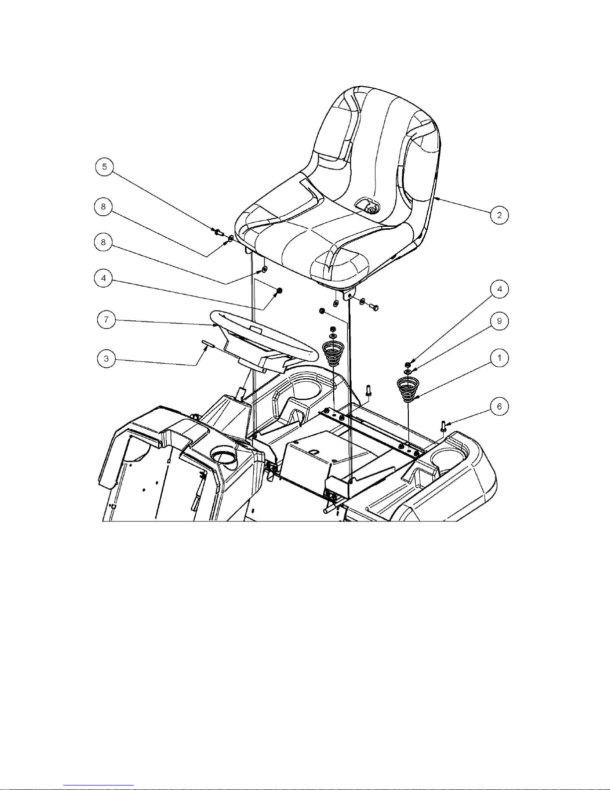
SEAT MOUNT & SEAT SPRINGS
Install the two seat springs using the
screws, washers, nuts, to the seat slide
frame, and tighten the screws, washers,
and nuts. Install the Seat & Mounting to
the seat slide frame using the Screws
and Nuts. Attach seat switch wiring to
seat switch.
CHECK TYRE PRESSURES &
FLUID LEVELS:
TYRES
Before operation ensure that tyre
pressures are equal on both sides.
Uneven pressure can give an uneven
finish when mowing and may cause
damage to tyres and/or tubes.
The recommended pressure is:
Front 170kPa (24 P.S.I.). Rear 140kPa (20 P.S.I.)
BATTERY
This machine is fitted with a maintenance
free battery.
ENGINE OIL
Before operation ensure that engine oil
level is to the full mark on the dipstick.
(Refer engine owners manual for
procedure & if oil needs to be added
refer Engine Owners Manual for Correct
Grade).
FUEL
Ensure there is fuel above the fuel tap &
the fuel tap at the bottom left front side
of fuel tank is turned to the on position
before attempting to start engine. (Use
unleaded fuel only).
Turn off fuel tap after use.
CLUTCH PLATE ADJUSTMENT
Loosen the four square head set screws
on the clutch plates using tube spanner
(AM006C1) and tommy bar (AM007).
Insert the clearance gauges supplied,
one between the forward clutch plate
and cone and the other between the
reverse clutch plate and cone and hook
them onto the intershaft. Slide both
clutch plates against the clearance
gauges and drive cone, tighten the set
screws firmly onto the flat on the
intershaft. Remove gauges.
CHECK OPERATION OF SAFETY
SWITCHES:
STARTING
Foot Switch - With the PTO (power
take off) switch in disengaged position
(off), attempt to start the engine without
depressing the foot switch.
Engine should not start.
PTO Switch - While sitting on seat
with foot on foot switch and PTO switch
in up (engaged) position, attempt to
start the engine.
Engine should not start.
Key Switch
With PTO switch in down (disengaged/
off) position & foot switch depressed
turn key switch to start position.
Engine should start.
STOPPING
Seat Switch - While sitting on seat
with engine running, engage cutter, and
lift weight from seat.
Engine should stop.
Key Switch
Sit on seat and start engine, turn key
switch to stop position.
Engine should stop.
OWNERS MANUAL FOR MODEL A16815G Live Drive rev 2 Page 7 1 February 2016
ITEM PART NUMBER DESCRIPTION QTY
1 A163060 Spring, Compression, Conical, Seat, Heavy 2
2
Sub-Assy, Seat, Sman 4500 1
3 DP10 Pin, Roll, Spring, 1/4"X1-3/4", Znpl 1
4 NM8NT Nut, Hex, Nyloc, Thin, M 8, Pc6, Znpl 4
5 SH0820M Screw, Hex, M 8x 20, Pc8.8, Znpl 2
6 SH0825M Screw, Hex, M 8x 25, Pc8.8, Znpl 2
7 SW14H Wheel, Steering, 14", 02hub+Cover 1
8 W051218 Washer, Flat, Bright, 5/16"X3/4"X18g, Znpl 4
9 W05M202 Washer, Flat, Bright, 5/16"X3/4"X14g 2
A168231 Cap, Spring, Seat 2
EXPLODED VIEW PRE DELIVERY

OWNERS MANUAL FOR MODEL A16815G Live Drive rev 2 Page 8 1 February 2016
IMPORTANT
RECOMMENDED FUEL
Unleaded fuel is recommended by
all manufacturers of engines fitted
to Cox products.
SAFETY SWITCHES
Before operating machine, ensure
that all safety switches are
operating correctly. Do not
operate machine with faulty,
mi ssi n g or dama ged safe ty
switches.
BLADE WARNING
Do not use mowing attachment
with broken or bent blades,
damaged or worn bolts and nuts or
damaged cutter disc, otherwise
damage and premature wear will
result from vibration. Replace
blades, bolts and nuts only in pairs
to maintain correct balance.
Recommended blade nut torque is
36-40Nm. Do not over tighten.
Keep both feet and
hands clear of the
mowing attachment at
all times while
attempting to start or
operate the machine.
WARNING
DO NOT OPERATE
WITHOUT MOWING
ATTACHMENT DEFLECTOR
FITTED & DOWN.
Safety footwear is recommended
when operating machine.
Reference to left or right hand side
of machine is determined by sitting
in the operating position on the
machine.
Mount and dismount only from left
hand side of machine.
Ensure machine has park brake
engaged when attempting to start
engine.
Never allow engine revs to exceed
more than 3600 RPM.
The Instruments,
the Controls and
their functions are
as follows;
Key Switch-
Used to start and stop engine. Insert
key, turn key all the way right to start
(3rd) position to start engine. When
key is released from start (3rd)
position it will return to on | (2nd)
position. Turn key all the way left to
off O (1st) position to stop engine.
Remove key from off O (1st) position
to lock ignition switch.
PTO Switch-
Used to activate the electromagnetic
clutch/brake to start (engage) and
stop (disengage and brake) mowing
attachment blades and allow starting
of engine with mowing attachment
blades disengaged from engine. With
engine running at fast speed pull
KNOB up to (ON) position to start
(engage) mowing attachment blades.
Push knob down to (OFF) position to
stop (disengage and brake) mowing
attachment blades.
Seat Switch-
Used to stop engine if operator is not
on the seat (switch not depressed) &
cutter engagement PTO switch is
engaged (on).
Start Foot switch -
Used to ensure drive is in neutral
when starting engine. Place right
foot on and depress foot switch to
start engine with switch key.
Hourmeter-
Used to indicate the number of hours
the engine has operated. Note:Ignition switch must be in the on
position for the hourmeter to display
hours.
Engine Speed/Choke Control
Lever-
Used to regulate engine speed and
cutter speed also to engage/regulate/
disengage the engine choke to assist
in starting a cold engine. Push LEVER
fully forward to engage the engine
choke fully.
Pull LEVER back so front edge of
LEVER is in line with the fast (rabbit)
symbol on dash decal to disengage
choke fully.
Pull LEVER back for slow engine
speed and push LEVER forward to
fast symbol on dash decal for fast
engine and cutter speed.
Seat Adjustment Lever-
Used to allow adjustment of the seat
backwards or forwards to give the
most comfortable operating position.
Pull the LEVER left to unlock the seat
slide mechanism, and move seat
backwards or forwards until most
comfortable operating position is
reached, release LEVER and attempt
to move the seat backwards or
forwards slightly to allow the LEVER
to return to the fully right position and
to ensure the seat is locked in
position.
Drive pedal-
Used to control an infinitely
variable ground speed between
zero and maximum in forward or
reverse. Also to select neutral.
With engine running push down on
front of pedal to travel forward.
With engine running push down on
back of pedal to travel in reverse.
When pressure is released from
front or back of pedal it will return
to neutral position. It is not
necessary to return to neutral or
stop before changing from forward
to reverse or reverse to forward.
Foot brake pedal-
Used to stop machine travel or keep
stationary before setting park brake.
Push pedal down to apply brake.
Remove foot from pedal to release
brake.
Park brake lever-
Used to keep machine stationary.
With drive pedal in neutral position
and machine stationary push lever
down and away from you to the ‘ON’
position to apply brake. To
release brake push lever down and
towards you then release, spring
tension will return the lever to the
‘OFF’ position.
NOTE– Applying park brake
while machine is moving
and/or attempting to drive
off with the park brake not
fully in the off position will
damage the teeth of the
large sprocket & park brake
mechanism or drive cone
and or clutch plates.
Mowing Attachment Cutting
Height Adjustment Lever-
Used to change the mowing
attachment cutting height. To alter
cutting height, lift lever slightly and
depress button, mover lever up to
raise or down to lower the mowing
attachment cut height, stop at desired
cutting height and release button to
lock at 1 of 10 height positions.
NOTE– Do Not mow in any
direction on slopes beyond 15
degrees (1 in 3.75).
OPERATING INSTRUCTIONS

OWNERS MANUAL FOR MODEL A16815G Live Drive rev 2 Page 9 1 February 2016
Fuel Tap Knob-
Used to shut off the fuel line to stop
fuel flow to the engine when the
tractor is transported or not in
operation to reduce the likelihood of
fuel leakage. Turn the KNOB
clockwise ¼ of a turn from the on
position to the off position to shut off
the fuel line to stop fuel flowing to the
engine. Turn KNOB anticlockwise ¼
of a turn from the off position to the
on position to allow fuel to flow to the
engine.
Oil Level Dipstick-
Used to indicate oil level in engine
when engine is not running. (Refer to
en g i n e owners m a n ual for
instructions on checking engine oil
level)
TO OPERATE
B E F O R E S T A R T I N G /
STOPPING:
See Engi ne Maintenance/
Instruction Sheet.
STARTING ENGINE
When starting engine, place right
heel on foot switch located on rear
of right footrest. Ensure that PTO
sw itch is di seng aged (of f),
otherwise electric starter motor will
not engage. If engine is cold
move engine speed control to
choke position and return to
desired engine speed setting when
engine starts. Do not attempt to
operate engine with engine speed
control lever in choke position.
STOPPING ENGINE
When stopping engine, ensure PTO
switch is disenagaged (off), and
engine speed control is in the fast
position, set park brake in the on
position, turn key switch to the
“off” (1st) position.
DRIVING
T O D RI V E F O RW A R D /
REVERSE:
Engine speed is regulated by the
engine speed control, set engine
speed control to desired engine
speed. Press down on the forward
section of the drive pedal for
forward movement, on the rear of
the drive pedal for reverse. The
amount of pressure can be used to
contr o l the gr o u n d spee d ,
especially in heavier conditions.
When operating the mower on
slopes greater than 10 degrees but
less than 15 degrees for a
pr olo nged p erio d, you m ay
experience minor drive fade,
should this occur, vary your
mowing style eg: mow around
some flat areas, then the slope
followed by the flat area again.
This will allow the drive to cool
before travelling up the slope
again.
N.B. Ens ure tha t when
pressure is applied to the drive
pedal rear wheels rotate or
damage will occur to drive
cone and or clutch plates.
MANOEUVRING:
Owing to the heel and toe type
action of the drive pedal, it is
possible to take the machine
straight from forward to reverse
and vice versa. This quick forward
and reverse operation makes the
machine very manoeuvrable and
the sharpest turns can be
negotiated easily and quickly.
TO BRAKE (WITH ENGINE
RUNNING):
The drive pedal may be used to
stop the machine. If travelling
forward push the pedal into
reverse until machine stops, then
bring the pedal back to neutral
position or vice versa if travelling
in reverse. Should a drive failure
occur during operation use the
brake pedal situated on the left
hand side and forward of where
your foot would rest during normal
operation.
TO BRAKE (WITH ENGINE
STOPPED):
Use foot brake pedal only.
Damage to drive cone will occur if
drive pedal is used to brake the
machine with the engine stopped.
P A R K I N G A N D
TRANSPORTATION BRAKE:
With the machine stationary,
depress the lever protruding out of
the left hand mudguard downward
and shift the lever to the left and
then up to engage the park brake.
Depress and shift to the right then
release to disengage the park
brake.
Do not engage parking brake
unless the machine has completely
stopped.
Do not attempt to drive with park
brake engaged, damage will occur
to drive cone and or clutch plates,
large drive sprocket, or park brake
mechanism.
NOTE: When mowing slopes,
keep drive pedal in forward or
reverse, depending on direction of
travel. The low gearing will
prevent it from picking up
excessive speed. If slope is very
steep it may be necessary to slow
engine speed slightly and /or,
apply light drive pedal pressure to
the opposite drive direction. i.e.
move drive pedal into reverse when
going forward down slope or into
forward when reversing down slope.
AVOID HOLDING MACHINE
STATIONARY ON SLOPES
USING DRIVE PEDAL WITH
ENGINE RUNNING AS DAMAGE
WILL OCCUR TO DRIVE CONE
AND OR CLUTCH PLATES.
OPERATING INSTRUCTIONS cont.

OWNERS MANUAL FOR MODEL A16815G Live Drive rev 2 Page 10 1 February 2016
MAINTENANCE INSTRUCTIONS
It is the owner’s responsibility to
ensure that all-periodical checks,
necessary adjustments, services and
repairs are carried out. Failure to do
so may result in death, personal injury
and/or property damage.
Before attempting any maintenance, stop
engine, ensure mowing attachment blades
have stopped rotating, disconnect spark plug
lead from spark plug and ground it, disconnect
battery at negative terminal, to prevent
accidental starting.
Position machine on a flat level surface for
maintenance.
Never alter factory setting of maximum engine
R.P.M (3600).
Reference to the left or right side of the
machine is determined by sitting in the
operating position.
IMPORTANT: If operating in adverse
conditions such as those mentioned below,
change engine oil, air filter, lubrication and
adjustments should be carried out at less time
intervals than specified in this booklets
maintenance schedule. Ensure machine has
park brake engaged when attempting to start
engine.
a. Mowing in hot or wet conditions.
b. Mowing in rough or dusty conditions.
c. Mowing hilly areas or continuous heavy
load conditions.
Ensure machine has park brake engaged when
attempting to start engine.
CHECK & ADJUST ENGINE OIL LEVEL Refer to engine owners manual for correct
method to check & adjust engine oil level.
CHANGE ENGINE OIL & OIL FILTER -
Refer to engine owner’s manual for correct
method to change engine oil & oil filter.
CHECK ENGINE AIR CLEANER & FOAM
PRE-CLEANER- Refer to engine owners
manual for correct method to check and
service engine air cleaner & foam pre-cleaner.
CHECK BONNET SIDE MESH - If mesh is
more than one quarter blocked by debris clean
mesh.
Wipe mesh with hand, rag or brush to remove
debris from mesh.
CHECK ENGINE ROTATING SCREEN-
Refer to engine owners manual for correct
method to check and clean engine rotating
screen /debris guard.
LUBRICATION OF MACHINE- Lubrication
of machine must be carried out every 15
hours of operation or once a month, whichever
occurs first. Lubricate at less time intervals
when operated under adverse conditions.
OILING: A few drops of oil should be placed
at the following points: Steering rod ends,
mower suspension link rod end, height
adjustment mechanism, pivot bolt and linkages
on clutch arm, clutch pedal and brake linkages.
CHAIN- Use only chain lube for lubrication
of the drive and steering chains.
GREASE POINTS- Grease nipples are
located on top of the front wheel stub axles
& the back of the drive arm.
GREASE STUB AXLES:
Clean grease nipple, use grease gun and
general-purpose grease to force old grease
from top and bottom of front axle bushes. Iif
grease is not released from bottom of bush
jack up front of machine and try again .
GREASE DRIVE ARM PIVOT-
Clean grease nipple, use grease gun and
general purpose grease to replenish lost
grease.
Under no circumstances allow grease or oil to
come into contact with the Drive Cone or
Clutch Plates. Should this occur, use petrol or
other suitable solvent and clean off immediately
whilst surfaces are cool and allow to dry before
operating machine.
ENGINE TO CONE DRIVE VEE BELT
ADJUSTMENT- Tension is automatically
adjusted by the belt tensioning spring.
ENGIN E TO C UT TE R V EE BE LT
ADJUSTMENT- Tension is automatically
adjusted by the belt tensioning springs.
CHEC K OP ER ATION OF SAF ET Y
SWITCHES:
STARTING
Foot Switch - With the PTO (power take
off) switch in disengaged position (off),
attempt to start the engine without
depressing the foot switch.
Engine should not start.
PTO Switch - While sitting on seat with
foot on foot switch and PTO switch in up
(engaged) position, attempt to start the
engine.
Engine should not start.
Key Switch
With PTO switch in down (disengaged/off)
position & foot switch depressed turn key
switch to start position.
Engine should start.
STOPPING
Seat Switch - While sitting on seat with
engine running, engage cutter, and lift
weight from seat.
Engine should stop.
Key Switch
Sit on seat and start engine, turn key
switch to stop position.
Engine should stop.
DRIVE CHAIN- Machines are fitted with
automatic chain adjusters. No adjustment
is required. Replace chain when chain has
sagged enough to expose half the depth of
the teeth on the bottom of the large
sprocket. Failure to replace worn chain will
cause premature wear of sprockets.
REPLACE DRIVE CHAIN- Stop engine,
ensure mowing attachment blades have
stopped rotating, disconnect spark plug
lead from spark plug and ground it,
disconnect battery at negative terminal, to
prevent accidental starting. Engage park
brake, jack up rear of machine, and
remove left rear wheel. Push chain
tensioner arms, one at a time, away from
chain and using a suitable spanner tighten
pivot bolt lock nuts to hold them out.
Release park brake then turn rear axle to
bring chain into a suitable position for
removal of the chain connecting link.
Remove connecting link and chain. Inspect
both sprockets for wear or damage, replace
if necessary. Install new chain and
connecting link with the link clip between
the wheel and chain. Release pivot arm
nuts until arm moves freely back to chain.
Engage park brake, install wheel and lower
machine.
TO ADJUST STEERING CHAIN- Stop
engine, ensure mowing attachment blades
have stopped rotating, disconnect spark
plug lead from spark plug and ground it,
disconnect battery at negative terminal, to
prevent accidental starting. Adjust chain by
loosening the two bolts which hold the
steering idler shaft mounting bracket in
position, slide rearwards to tension chain
then retighten bolts.
CUTTER HEIGHT ADJUSTMENT- Stop
engine, ensure mowing attachment blades
have stopped rotating, disconnect spark
plug lead from spark plug and ground it,
disconnect battery at negative terminal, to
prevent accidental starting. If the Mowing
Attachment can not be positioned to give a
satisfactory grass cut height using the
available notches on the cut height
mechanism, position the mower on a
smooth level surface, lock the park brake
on, and lower the Mowing Attachment to
the notch above the desired cut height.
Place 3 equal height spacers (that can
support the mowing attachments weight) ,
of the desired height, under the mowing
attachment one on each side at the lower
front adjacent to the cut-out & one at the
middle of the back and lower the Mowing
Attachment onto them. Loosen the 2 short
screws located together on the front of the
rear suspension mount. Push the rear link
rearwards until it stops and retighten the 2
screws. Lift the Mowing attachment off the
spacers and remove the spacers and check
the cut height is as desired and the deck is
level to slightly higher (3—5 mm) at the
back. Adjust height again if required.
CU T T E R B R A K E A D J US T M E N T -
Automatically adjusted by permanent
magnets on the electro magnetic clutch/
brake.
REPLACE BLADES- Stop engine, ensure
mowing attachment blades have stopped
rotating, disconnect spark plug lead from spark
plug and ground it, disconnect battery at
negative terminal, to prevent accidental
starting. Check condition of cutter disc
remove the blade nut using a suitable
spanner (if using a socket remove the
blanking grommet to gain access to the
blade nut) and replace all blades, bolts, nuts
and washers to preserve balance, tighten
blade nut to (36-40Nm). Do not over
tighten. Re-fit blanking grommet if removed.

OWNERS MANUAL FOR MODEL A16815G Live Drive rev 2 Page 11 1 February 2016
Check engine oil level, adjust if required
Check engine air cleaner foam pre-cleaner, service if req.
Check engine rotating screen/finger guard, clean if required
Check operation of safety switches, service if required
Check foot brake operation, adjust if required.
Check tyre pressures, adjust if required
Check for loose fasteners, tighten if required
Lubricate stub axles, steering ball joints, Drive Chain
Check mowing attachment cutter blades, bolts, nuts, disc/s, housing,
and guards for wear or damage, replace if required
BEFORE EXTENDED STORAGE
BEFORE EXTENDED STORAGE
BEFORE EXTENDED STORAGE
MAINTENANCE SCHEDULE
BEFORE EACH USE
BEFORE EACH USE
BEFORE EACH USE
Check engine oil level, adjust if required
Check engine air cleaner foam pre-cleaner, service if required
Check engine rotating screen/finger guard, clean if required
Check operation of safety switches, service if required
Check foot brake operation, adjust if required.
Check tyre pressures, adjust if required
Check for loose fasteners, tighten if required
Lubricate stub axles
Lubricate steering ball joints
Lubricate Drive Chain
Check mowing attachment cutter blades, bolts, nuts, disc/s,
housing, and guards/deflector for wear or damage, replace if required
Change engine oil - Clean machine - Lubricate fully - Remove all fuel from engine, fuel lines & tank or add fuel stabiliser
EVERY 5 HOURS
EVERY 5 HOURS
EVERY 5 HOURS
TO REMOVE MOWING ATTACHMENT –
Stop engine, ensure mowing attachment blades
have stopped rotating, and spark plug lead is
disconnected & grounded, disconnect battery
negative terminal to prevent accidental starting,
disconnect the belt tensioning spring (front left
hand side of mowing attachment). Lower
mowing attachment onto 20mm block front and
rear. Remove cutter belt from engine pulley.
Remove two M10 x 50mm bolts, nuts &
washers from mower suspension link at rear of
the mowing attachment. Remove mowing
attachment pivot pin lock screw and nut (6mm)
and remove mowing attachment pivot pin.
Remove the M8x35mm bolt from the cradle
frame attachment bracket. Turn the front
wheels a little to the left and twist the mowing
attachment to the right and slide the deck from
under the mower ro the right side.
Re-assemble in reverse order. To assist in
refitting mowing attachment pivot pin, raise the
mowing attachment slightly. Refit mower
suspension link & lifting links and M10x50mm
bolts, nuts and washers. Refit cutter belt,
connect belt tensioning spring and refit spark
plug lead and battery terminal.
CLUTCH PLATE ADJUSTMENT- Periodically
adjust the clutch plates as the cone drive
wears. Stop engine, ensure mowing
attachment blades have stopped rotating,
disconnect spark plug lead from spark plug
and ground it, disconnect battery at
negative terminal, to prevent accidental
starting. Carry out this operation, with
engine off. Centre the clutch arm assembly to
the neutral position. Loosen the four square
head set screws on the clutch plates using
tube spanner (AM006C1) and tommy bar
(AM007). Insert the clearance gauges
supplied, one between the forward clutch plate
and cone and the other between the reverse
clutch plate and cone and hook them onto the
intershaft. Slide both clutch plates against the
clearance gauges and cone, tighten the set
screws firmly onto the flat on the intershaft.
Remove gauges.
CHECK TYRE PRESSURES - Uneven
pressure can give an uneven finish when
mowing and overly low or high pressures
may cause damage to tyres and/or tubes.
The recommended pressure is: 170kPa (24
P.S.I.)Front. 140kPa (20 P.S.I.) Rear.
BATTERY MAINTENANCE- Batteries can be
dangerous as they contain acids (corrosive
chemicals), flammable vapours, large amounts
of stored electrical energy, which may cause
chemical burns, explosions or fires. Where
goggles and a protective face guard. Remove
jewellery/watches before handling the battery.
Do not perform any battery maintenance
where there are open flames or the possibility
of sparks. Always work in a well ventilated
area. Ensure the top of the battery is clean
and dry (free of dirt and grime) as a dirty
battery can discharge across the top of the
battery casing. Inspect the terminals, screws
and cables for breakage, damage or loose
connections and they are clean, tight and free
of corrosion. When not in use, a battery
discharges by as much as 1% a day, more
when the climate is warm. To make up for
this loss, a boosting charge should be given
once a month. Disconnect battery terminals
(negative terminal first) to charge, then
allow to stand minimum 1/2hr before reconnecting (negative terminal first). If a
battery is not used for a period of more
than three (3) months, the terminals should
be disconnected and trickle charged at two
(2) amps for two (2) hours once every three
(3) months or before use. At the end of any
maintenance ensure the battery is securely
fastened in place, especially if it has been
removed.
BRAKE ADJUSTMENT- Remove the ‘R’ pin
securing the adjustable link rod to the brake
lever & turn adjustable link rod clockwise push
adjustable link rod into machine & refit link rod
to pedal & refit ‘R’ Pin.
CLEANING MACHINE WITH WATER
PRESSURE – Allow machine to cool down (min
2 hrs) before hosing down. Start engine and
engage drive and cutting systems to clear water
from pulleys and belts. Stop engine and allow
machine to dry. Lubricate as required. Do not
cover machine with plastic or vinyl type
material.
C L E A N I N G A ND P O L IS H I N G
POLYETHYLENE BONNET AND REAR
MUDGUARD- To keep scratches on bonnet
and mudguard to minimum, do not rub or
brush off with bare hands, use a soft cloth
or a light flow of compressed air. For dirt,
wash with a steady stream of water only
(no detergent), then blow off excess water
with air. To polish remove excess dust or
dirt. When surface is dry, spray on an
automotive type plastic preservative and
leave on for 30 to 60 seconds. Using a dry
soft cloth (i.e. cheesecloth) wipe off to bring
up lustre.
GENUINE SPARE PARTS- Always use
Genuine Cox Factory Made Spare Parts.
Use of non-genuine COX spares will void
your warranty.
SAFETY FIRST- The use of mechanical
devices can cause injury or property damage
if incorrect procedures are used. Please
ensure all operators & users read &
understand all safety instructions in this
manual.
CHECK FOR LOOSE FASTENERS TORQUE SETTINGS
1/4” UNC BOLT/NUT 10Nm (84lbf in)
5/16” UNC BOLT/NUT 20Nm (180lbf in)
3/8” UNC BOLT/NUT 36Nm (27lbf ft)
5/8” UNF NUT 100Nm (74lbf ft)
7/16” UNF BOLT 68Nm (50lbf ft)
6mm BOLT/NUT 9Nm (80lbf in)
8mm BOLT/NUT 15Nm (11lbf ft)
10mm NUT 44Nm (32lbf ft)
12mm NUT 53Nm (39lbf ft)
20mm NUT 100Nm (74lbf ft)
MAINTENANCE INSTRUCTIONS CONT.

OWNERS MANUAL FOR MODEL A16815G Live Drive rev 2 Page 12 1 February 2016
Change engine oil filter
Change engine oil
Check engine spark plug, clean, adjust, or replace if required
If fitted clean engine exhaust spark arrester
Check engine air cleaner foam pre-cleaner , service if required *
Check engine air cleaner cartridge, service if required*
Clean engine cooling system*
Check clutch arm action, adjust if required
Replace in-line fuel filter
Check foot brake operation and lining for ware, adjust or replace if req
Lubricate stub axles, steering ball joints, Drive Chain
Check for loose fasteners, tighten if required
Check operation of safety switches, service if required
Check tyre pressures, adjust if required
Check drive chain and sprockets for wear, replace if required
Check steering chain an sprockets or wear, adjust if required
Check mowing attachment cutter blades, bolts, nuts, disc/s, housing,
and guards for wear or damage, replace if required
Check clutch arm action, adjust if required
Re-tension rear wheel retaining nut/s
Check battery condition, service if required
Check drive clutch plates and cone for wear or damage, adjust or
service if required
Check belts for wear or damage, replace if required
Check engine to clutch vee belt
Check cutter vee belt and adjust cutter housing level if required
9 MONTHS OR 75 HOURS WHICH EVER OCCURS F
9 MONTHS OR 75 HOURS WHICH EVER OCCURS F
9 MONTHS OR 75 HOURS WHICH EVER OCCURS F
IRST
IRST
IRST
Change engine oil if operating under heavy load or high ambient
temperature
Check engine air cleaner foam pre-cleaner, service if required *
Check engine rotating screen/finger guard, clean if required *
Check foot brake operation, adjust if required
Check operation of safety switches and replace if required
Check tyre pressures, adjust if required
Lubricate stub axles, steering ball joints, Drive Chain
Check mowing attachment cutter blades, bolts, nuts, disc/s, housing ,
and guards for wear or damage, replace if required
Check for loose fasteners, tighten if required
Check battery condition, service if required
Check cutter vee belt and adjust cutter housing level if required
Check vee belt s
12 MONTHS OR 100 HOURS WHICH EVER OCCURS FIRST
12 MONTHS OR 100 HOURS WHICH EVER OCCURS FIRST
12 MONTHS OR 100 HOURS WHICH EVER OCCURS FIRST
*Service more often under dusty conditions, or where air borne debris is present
DATE / / HOURS...............CUSTOMER/DEALER................................................
DATE / / HOURS..........................DEALER................................................
*Service more often under dusty conditions, or where air borne debris is present
*Service more often under dusty conditions, or where air borne debris is present
DATE / / HOURS..........................DEALER................................................
Change engine oil if operating under heavy load or high ambient
temperature
Check engine air cleaner foam pre-cleaner, service if required *
Check engine rotating screen/finger guard, clean if required *
Check foot brake operation, adjust if required
Check operation of safety switches and replace if required
Check tyre pressures, adjust if required
Lubricate stub axles, steering ball joints, Drive Chain
Check mowing attachment cutter blades, bolts, nuts, disc/s,
housing ,and guards for wear or damage, replace if required
Check for loose fasteners, tighten if required
Check vee belt s
Check battery condition, service if required
Check cutter vee belt and adjust cutter housing level if required
6 MONTH OR 50 HOURS
6 MONTH OR 50 HOURS
6 MONTH OR 50 HOURS
WHICH EVER OCCURS FIRST
WHICH EVER OCCURS FIRST
WHICH EVER OCCURS FIRST
DATE / / HOURS..........................DEALER................................................
FIRST MONTH OR 5 HOURS WH
FIRST MONTH OR 5 HOURS WH
FIRST MONTH OR 5 HOURS WH
ICH EVER OCCURS FIRST
ICH EVER OCCURS FIRST
ICH EVER OCCURS FIRST
Change engine oil
Check engine air cleaner foam pre-cleaner , service if required
Check engine rotating screen/finger guard, clean if required
Check foot brake operation, adjust if required
Check operation of safety switches, service if required
Check tyre pressures, adjust if required
Lubricate stub axles, steering ball joints, Drive Chain
Check mowing attachment cutter blades, bolts, nuts, disc/s, housing ,
and guards for damage, replace if required
Check clutch arm action, adjust if required
Check vee belt s
Check for loose fasteners, tighten if required
Check cutter vee belt and adjust cutter housing level if required
DATE / / HOURS.......................CUSTOMER................................................
3 MONTH OR 25 HOURS
3 MONTH OR 25 HOURS
3 MONTH OR 25 HOURS
WHICH EVER OCCURS FIRST
WHICH EVER OCCURS FIRST
WHICH EVER OCCURS FIRST
Change engine oil if operating under heavy load or high ambient temperature Check engine air cleaner foam pre-cleaner, service if required *
Check engine rotating screen/finger guard, clean if required *
Check foot brake operation, adjust if required
Check operation of safety switches and replace if required
Check tyre pressures, adjust if required
Lubricate stub axles, steering ball joints, Drive Chain
Check mowing attachment cutter blades, bolts, nuts, disc/s, housing ,
and guards for wear or damage, replace if required
Check vee belt s
Check battery condition, service if required
Check cutter vee belt and adjust cutter housing level if required
Check for loose fasteners, tighten if required
*Service more often under dusty conditions, or where air borne debris is present

OWNERS MANUAL FOR MODEL A16815G Live Drive rev 2 Page 13 1 February 2016
21 MONTHS OR 175 HOURS WHICH EVER OCCURS FIRST
21 MONTHS OR 175 HOURS WHICH EVER OCCURS FIRST
21 MONTHS OR 175 HOURS WHICH EVER OCCURS FIRST
Change engine oil if operating under heavy load or high ambient
temperature
Check engine air cleaner foam pre-cleaner, service if required *
Check engine rotating screen/finger guard, clean if required *
Check foot brake operation, adjust if required
Check operation of safety switches and replace if required
Check tyre pressures, adjust if required
Lubricate stub axles, steering ball joints, Drive Chain
Check mowing attachment cutter blades, bolts, nuts, disc/s, housing ,
and guards for wear or damage, replace if required
Check battery condition, service if required
Check for loose fasteners, tighten if required
Check cutter vee belt and adjust cutter housing level if required
Check vee belt s
24 MONTHS OR 200 HOURS WHICH EVER OCCURS FIRST
24 MONTHS OR 200 HOURS WHICH EVER OCCURS FIRST
24 MONTHS OR 200 HOURS WHICH EVER OCCURS FIRST
*Service more often under dusty conditions, or where air borne debris is present
DATE / / HOURS...............CUSTOMER/DEALER................................................
Replace engine oil filter
Change engine oil
Check engine spark plug, clean, adjust, or replace if required
If fitted clean engine exhaust spark arrestor
Check engine air cleaner foam pre-cleaner , service if required *
Check engine air cleaner cartridge, service if required
Clean engine cooling system*
Check foot brake operation and lining for ware, adjust or replace if
required
Check operation of safety switches, service if required
Check tyre pressures, adjust if required
Lubricate stub axles, steering ball joints, Drive Chain
Check steering chain an sprockets or wear, adjust if required
Check mowing attachment cutter blades, bolts, nuts, disc/s, housing,
and guards for wear or damage, replace if required
Check belts for wear or damage, replace if required
Check drive chain and sprockets for wear, replace if required
Check drive clutch plates and cone for wear or damage,
adjust or service if required
Check clutch arm action, adjust if required
Check battery condition, service if required
Check for loose fasteners, tighten if required
Check vee belt s
Check cutter vee belt and adjust cutter housing level if required
*Service more often under dusty conditions, or where air borne debris is present
DATE / / HOURS..........................DEALER................................................
Change engine oil
If fitted clean engine exhaust spark arrestor
Check engine air cleaner foam pre-cleaner , service if required *
Check engine rotating screen/finger guard , clean if required *
Check foot brake operation and lining for ware, adjust or replace if
required
Check operation of safety switches, service if required
Check tyre pressures, adjust if required
Lubricate stub axles, steering ball joints, Drive Chain
Check steering chain an sprockets or wear, adjust if required
Check mowing attachment cutter blades, bolts, nuts, disc/s, housing,
and guards for wear or damage, replace if required
Check belts for wear or damage, replace if required
Check drive chain and sprockets for wear, replace if required
If fitted check mowing attachment brake pad for wear, replace if required
Check drive clutch plates and cone for wear or damage,
adjust or service if required
Check clutch arm action, adjust if required
Check battery condition, service if required
Check for loose fasteners, tighten if required
Check vee belt s
Check cutter vee belt and adjust cutter housing level if required
*Service more often under dusty conditions, or where air borne debris is present
15 MONTHS OR 125 HOURS WHICH EVER OCCURS FIRST
15 MONTHS OR 125 HOURS WHICH EVER OCCURS FIRST
15 MONTHS OR 125 HOURS WHICH EVER OCCURS FIRST
DATE / / HOURS................CUSTOMER/DEALER................................................
18 MONTHS OR 150 HOURS WHICH EVER OCCURS FIRST
18 MONTHS OR 150 HOURS WHICH EVER OCCURS FIRST
18 MONTHS OR 150 HOURS WHICH EVER OCCURS FIRST
*Service more often under dusty conditions, or where air borne debris is present
DATE / / HOURS..........................DEALER................................................
Change engine oil if operating under heavy load or high ambient
temperature
Check engine air cleaner foam pre-cleaner, service if required *
Check engine rotating screen/finger guard, clean if required *
Check operation of safety switches and replace if required
Check foot brake operation, adjust if required
Lubricate stub axles, steering ball joints, Drive Chain
Check tyre pressures, adjust if required
Check battery condition, service if required
Check mowing attachment cutter blades, bolts, nuts, disc/s, housing,
and guards for wear or damage, replace if required
Check for loose fasteners, tighten if required
Check cutter vee belt and adjust cutter housing level if required
Check vee belt s

OWNERS MANUAL FOR MODEL A16815G Live Drive rev 2 Page 14 1 February 2016
We are proud that you have purchased a Cox product and urge you to follow these
instructions to obtain the maximum life for your machine.
If in doubt check with your supplier.
33 MONTHS OR 275 HOURS WHICH EVER OCCURS FIRST
33 MONTHS OR 275 HOURS WHICH EVER OCCURS FIRST
33 MONTHS OR 275 HOURS WHICH EVER OCCURS FIRST
Change engine oil if operating under heavy load or high ambient
temperature
Check engine air cleaner foam pre-cleaner, service if required *
Check engine rotating screen/finger guard, clean if required *
Check foot brake operation, adjust if required
Check operation of safety switches and replace if required
Check tyre pressures, adjust if required
Lubricate stub axles, steering ball joints, Drive Chain
Check mowing attachment cutter blades, bolts, nuts, disc/s, housing , and guards for wear or damage, replace if required
Check battery condition, service if required
Check for loose fasteners, tighten if required
Check cutter vee belt and adjust cutter housing level if required
Check vee belt s
*Service more often under dusty conditions, or where air borne debris is present
DATE / / HOURS.................CUSTOMER/DEALER................................................
36 MONTHS OR 300 HOURS WHICH EVER OCCURS FIRST
36 MONTHS OR 300 HOURS WHICH EVER OCCURS FIRST
36 MONTHS OR 300 HOURS WHICH EVER OCCURS FIRST
Replace engine oil filter
Change engine oil
Check engine spark plug, clean, adjust, or replace if required
If fitted clean engine exhaust spark arrestor
Check engine air cleaner foam pre-cleaner , service if required *
Check engine air cleaner cartridge, service if required
Clean engine cooling system*
Check foot brake operation and lining for ware, adjust or replace if
required
Check operation of safety switches, service if required
Check tyre pressures, adjust if required
Lubricate stub axles, steering ball joints, Drive Chain
Check steering chain an sprockets or wear, adjust if required
Check mowing attachment cutter blades, bolts, nuts, disc/s, housing, and guards for wear or damage, replace if required
Check belts for wear or damage, replace if required
Check drive chain and sprockets for wear, replace if required
Check drive clutch plates and cone for wear or damage,
adjust or service if required
Check clutch arm action, adjust if required
Check battery condition, service if required
Check for loose fasteners, tighten if required
Check vee belt s
Check cutter vee belt and adjust cutter housing level if required
*Service more often under dusty conditions, or where air borne debris is present
DATE / / HOURS..........................DEALER................................................
27 MONTHS OR 225 HOURS WHICH EVER OCCURS FIRST
27 MONTHS OR 225 HOURS WHICH EVER OCCURS FIRST
27 MONTHS OR 225 HOURS WHICH EVER OCCURS FIRST
Change engine oil if operating under heavy load or high ambient temperature
Check engine air cleaner foam pre-cleaner, service if required *
Check engine rotating screen/finger guard, clean if required *
Check foot brake operation, adjust if required
Check operation of safety switches and replace if required
Check tyre pressures, adjust if required
Lubricate stub axles, steering ball joints, Drive Chain
Check mowing attachment cutter blades, bolts, nuts, disc/s, housing ,
and guards for wear or damage, replace if required
Check battery condition, service if required
Check for loose fasteners, tighten if required
Check cutter vee belt and adjust cutter housing level if required
Check vee belt s
*Service more often under dusty conditions, or where air borne debris is present
DATE / / HOURS................CUSTOMER/DEALER................................................
30 MONTHS OR 250 HOURS WHICH EVER OCCURS FIRST
30 MONTHS OR 250 HOURS WHICH EVER OCCURS FIRST
30 MONTHS OR 250 HOURS WHICH EVER OCCURS FIRST
Change engine oil
If fitted clean engine exhaust spark arrestor
Check engine air cleaner foam pre-cleaner , service if required *
Check engine rotating screen/finger guard , clean if required *
Check foot brake operation and lining for ware, adjust or replace if
required
Check operation of safety switches, service if required
Check tyre pressures, adjust if required
Lubricate stub axles, steering ball joints, Drive Chain
Check steering chain an sprockets or wear, adjust if required
Check mowing attachment cutter blades, bolts, nuts, disc/s, housing, and guards for wear or damage, replace if required
Check belts for wear or damage, replace if required
Check drive chain and sprockets for wear, replace if required
Check drive clutch plates and cone for wear or damage,
adjust or service if required
Check clutch arm action, adjust if required
Check battery condition, service if required
Check for loose fasteners, tighten if required
Check vee belt s
Check cutter vee belt and adjust cutter housing level if required
*Service more often under dusty conditions, or where air borne debris is present
DATE / / HOURS..........................DEALER................................................
OWNERS MANUAL FOR MODEL A16815G Live Drive rev 2 Page 15 1 February 2016
OWNERS MANUAL FOR MODEL A16815G Live Drive rev 2 Page 16 1 February 2016
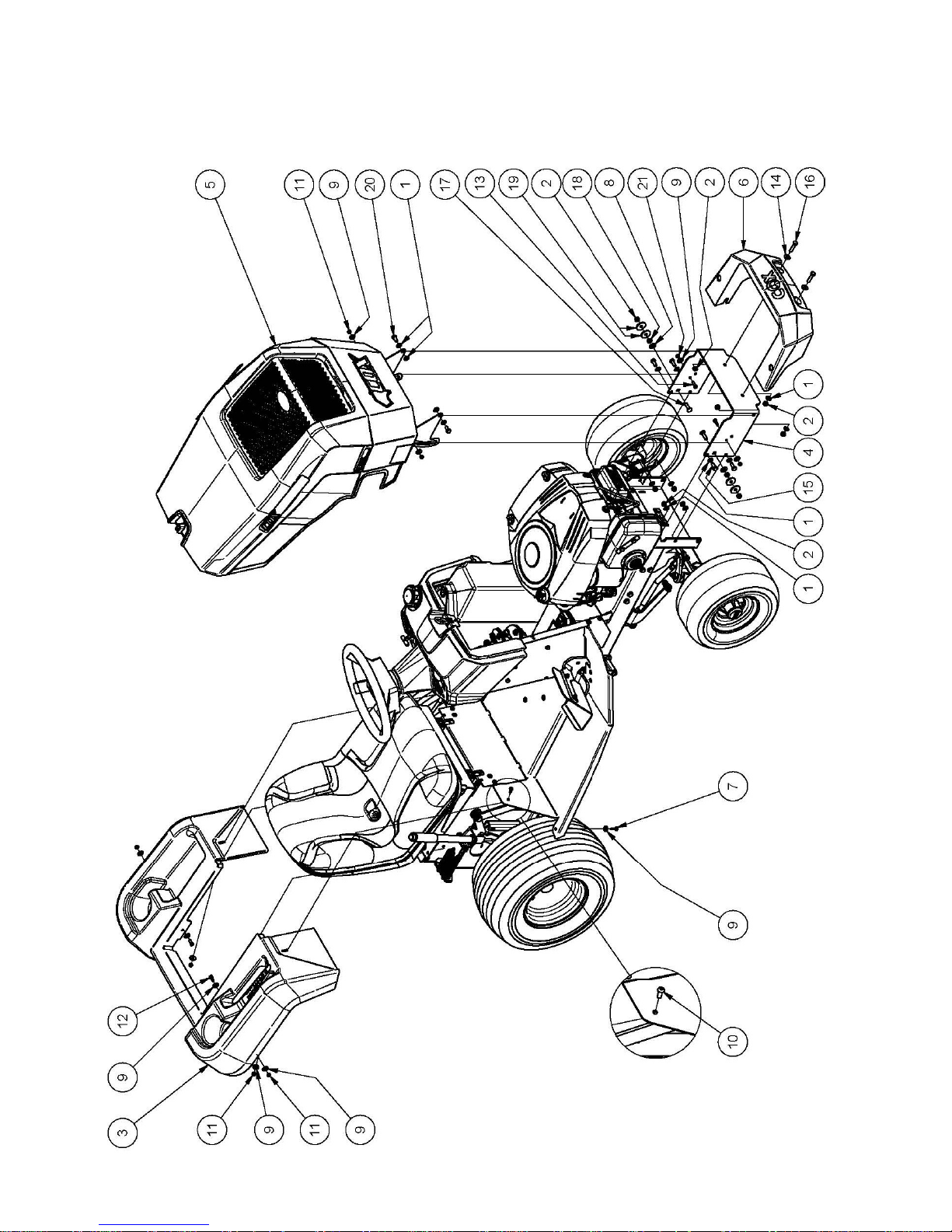
PARTS LIST: A16815G BODY - BONNET & MUDGUARD

OWNERS MANUAL FOR MODEL A16815G Live Drive rev 2 Page 17 1 February 2016
PARTS LIST: A16815G BODY - BONNET & MUDGUARD
ITEM PART NUMBER DESCRIPTION QTY
1 W08MN Washer, Flat, Bright, M 8x 17x1, 2 14
2 NM8NT Nut, Hex, Nyloc, Thin, M 8, Pc6 10
3 A168022 Mudguard, Rear 1
4 A163066R Bar, Bumper, Red 1
5 Sub-Assy, Bonnet, Sman 4500, B&S, 19.0 1
6 A163014 Bumper, Front 1
7 SPPK6X20 Screw, Pan, Posi3, K 6x 20 2
8 W10MN Washer, Flat, Bright, M10x 21x1.6 2
9 W041216 Washer, Flat, Bright, 1/4"X3/4"X16g 12
10 BHSSM6X16 Screw, Button, Hex Soc, M 6x 16, Pc10.9 2
11 NM6NT Nut, Hex, Nyloc, Thin, M 6, Pc6 6
12 SH0616M Screw, Hex, M 6x 16, Pc4.6 2
13 SH0620M Screw, Hex, M 6x20, Pc4.6 2
14 W05M202 Washer, Flat, Bright, 5/16"X3/4"X14g 2
15 SH0820M Screw, Hex, M 8x 20, Pc8.8 4
16 B0835M Bolt, Hex, M8 X 35, Pc8.8 2
17 BCHSNM8X30 Bolt, Cup, Sq Neck, M8 X 30 Pc4.6. 2
18 NHM8 Nut, Hex, M8 2
19 W052003 Washer, Flat, Black, 5/16"X1-1/4"X3 4
20 SH0816M Screw, Hex, M 8x 16, Pc8.8 2
21 NHM6 Nut, Hex, M 6, Pc5 2
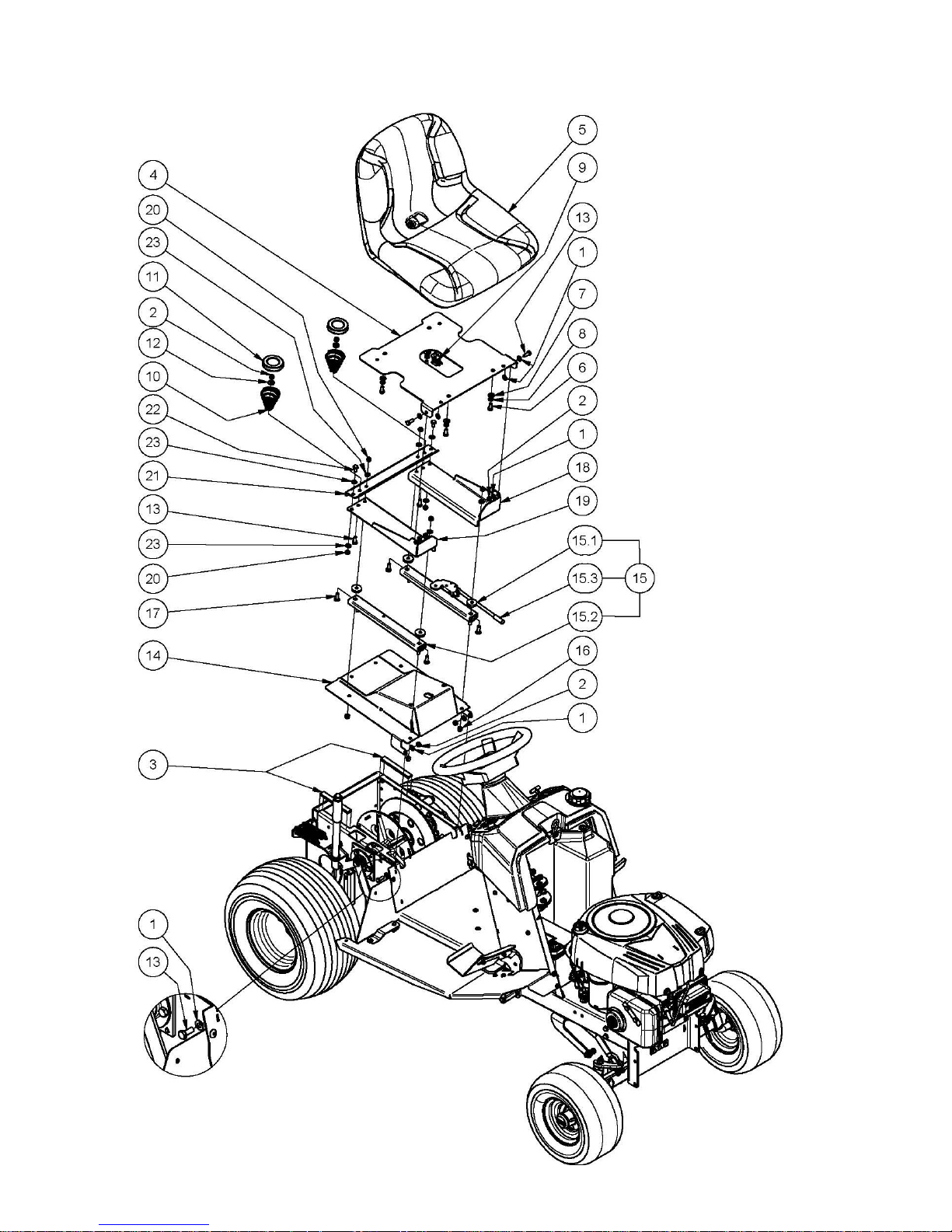
OWNERS MANUAL FOR MODEL A16815G Live Drive rev 2 Page 18 1 February 2016
PARTS LIST: A16815G BODY - SEAT
 Loading...