

Page 1

www.CoxBusiness.com
SIP T runking Configuration Guide
for
Cisco UC320
Firmware Release 2.1.1
© 2011, Cox Communications, Inc. All rights reserved.
This documentation is the confidential and proprietary intellectual property of Cox
Communications, Inc. Any unauthorized use, reproduction, preparation of derivative works,
performance, or display of this document, or software represented by this document is strictly
prohibited.
Page 2

Table of Contents
Audience................................................................................................................................................3
1
2 Introduction............................................................................................................................................3
3 SIP Trunking Network Components ......................................................................................................4
3.1 Hardware Components...................................................................................................................5
3.2 EdgeMarc 4550 e-SBC Software Requirements............................................................................5
4 Features.................................................................................................................................................5
4.1 SIP Registration Method.................................................................................................................5
4.2 Features Supported........................................................................................................................5
4.3 Features Not Supported.................................................................................................................5
5 Caveats and Limitations.........................................................................................................................5
5.1 IP Address Worksheet....................................................................................................................6
5.2 Cisco Network Configuration..........................................................................................................7
5.2.1 Network Topology ...................................................................................................................7
5.2.2 WAN Network..........................................................................................................................8
5.2.3 Voice VLAN.............................................................................................................................9
5.2.4 UC320 Administrative Network Access...................................................................................9
6 SIP Trunk Configuration.......................................................................................................................10
6.1.1 SIP Trunking Configuration...................................................................................................10
6.2 Cisco UC320 Apply Changes.......................................................................................................12
6.2.1 Adding and Removing Platform Modification Files................................................................13
Table of Figures
Figure 1 - Cox Fiber Network........................................................................................................................3
Figure 2 - SIP Trunk Lab Reference Network...............................................................................................4
Figure 5-1 UC320 Routes Voice Only Network Topology ............................................................................7
Figure 5-2 Network WAN Internet Configuration..........................................................................................8
Figure 5-3 Voice VLAN .................................................................................................................................9
Figure 6-1 SIP Trunking Configuration Parameters: 1 of 2.........................................................................10
Figure 6-2 SIP Trunking Configuration Parameters: 2 of 2.........................................................................11
Figure 6-3 Site Summary............................................................................................................................12
Figure 6-4 Network Summary Detail...........................................................................................................12
Figure 6-5 Devices: Upgrade PMF Files.....................................................................................................13
Figure 6-6 Platform Modification Files ........................................................................................................13
Table of Tables
Table 1 – IP Addresses.................................................................................................................................6
Page 2 of 13
Property of Cox Communications, Inc. Version 1.0
Page 3
1 Audience
This document is intended for the SIP trunk customer’s technical staff and Value Added Retailer (VAR)
having installation and operational responsibilities.
2 Introduction
This Configuration Guide describes configuration steps for Cox SIP trunking to a Cisco UC-320 PBX. Cox
SIP trunking is a scalable and efficient IP trunking telecommunication solution for your business that
provides all the traditional services such as Direct Inward Dialing, Hunting, Calling Name, Calling Number,
Local/Long Distance and Business Continuity options, including:
Burstable Trunk Capacity – Dynamically increases call capacity during peak busy periods so your
customers never receive a busy signal.
Call Forward Always – On the trunk group pilot number for all calls in case of an outage (i.e.,
flood, fire, loss of power, etc.).
Call Forward Not Reachable – On the trunk group pilot number that operates on a per-call
contingency basis to forward the call to any PSTN number (i.e., call center or alternate office
location) during temporary call completion impairments.
Route Exhaustion – Automatic reroute of trunk group calls to any PSTN phone number (i.e., a call
center) if calls can’t be completed to the PBX.
Support for geo-redundant PBX deployments and automatic reroute of SIP trunks to the backup
customer data center.
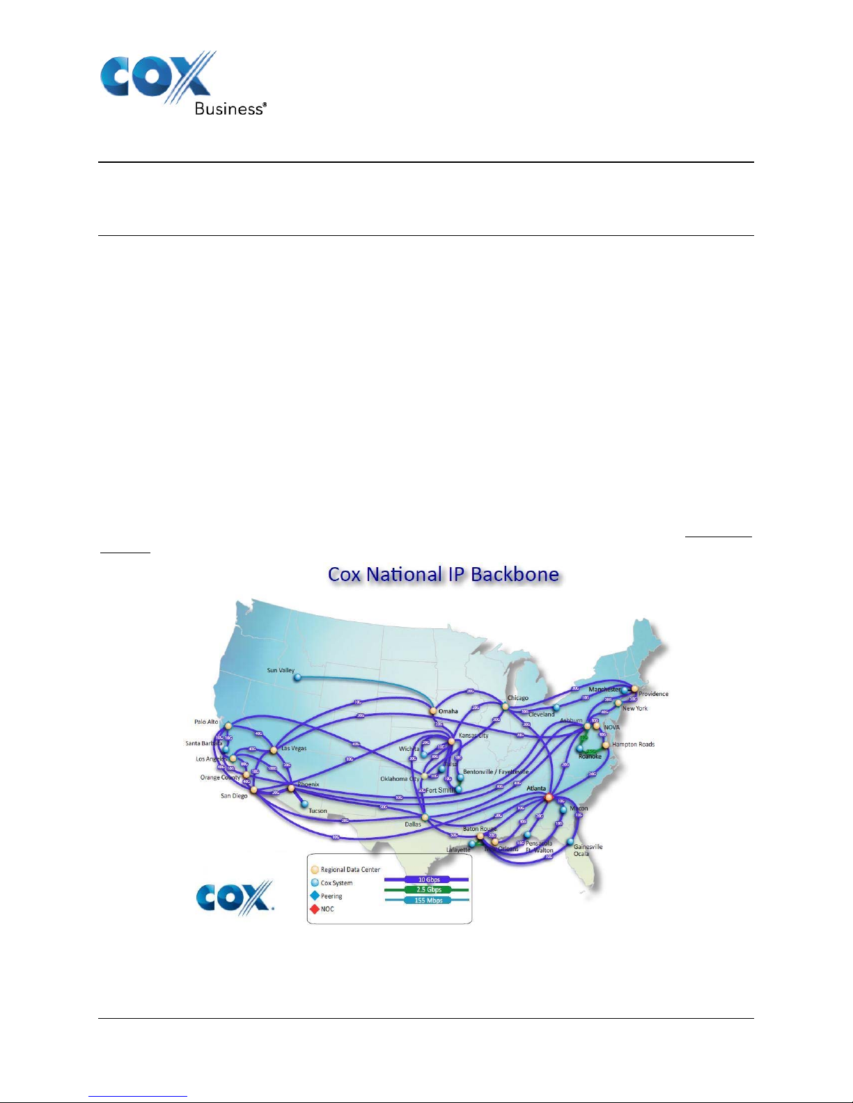
All calls are routed over Cox’s national fiber network with guaranteed Quality of Service (QoS); calls never
traverse the Internet.
Page 3 of 13
Property of Cox Communications, Inc. Version 1.0
Figure 1 - Cox Fiber Network
Page 4
3 SIP Trunking Network Components
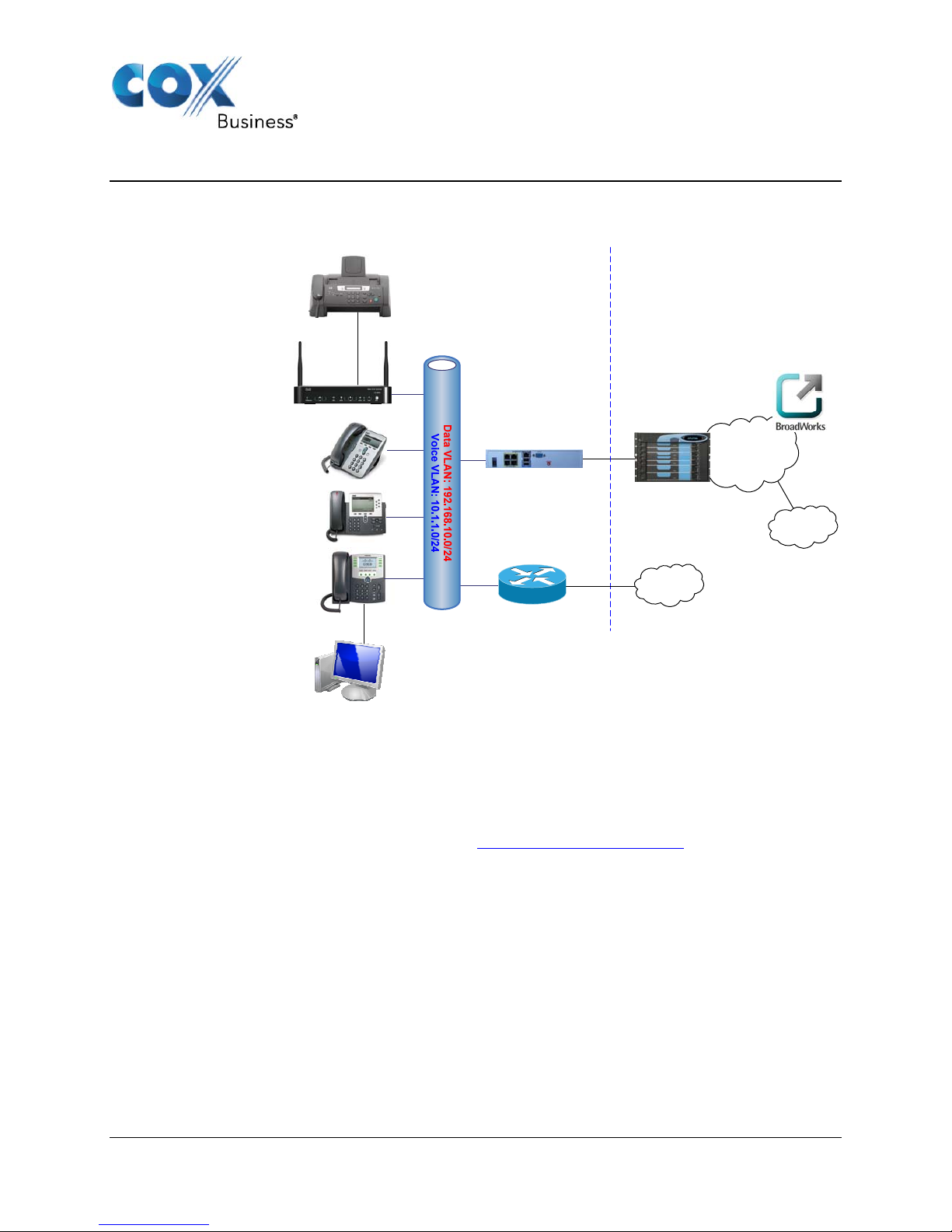
The network for the SIP trunk reference configuration is illustrated below and is representative of a Cisco
UC320 network configuration.
Customer Premise Cox
Analog Fax
FXS
DHCP Server for Voice VLAN
Data VLAN Static IP: 192.168.10.2
Trunk Group Pilot #: 678-236-7400
Cisco UC320 PBX
Static WAN IP: 192.168.1.2
Voice VLAN IP: 10.1.1.1
Voice VLAN DHCP IP: 10.1.1.2
DID: 678-236-7401
Cox E-SBC
Static LAN IP: 192.168.1.1
Net Mask: 255.255.255.0
SIP Call Server
Acme Packet
Net-Net 9200
Session Border
Controller (SBC)
Cox
IP Network
Voice VLAN DHCP IP: 10.1.1.3
DID: 678-236-7402
Voice VLAN DHCP IP: 10.1.1.4
DID: 678-236-7403
Data VLAN DHCP IP:
192.168.10.x
Data VLAN
PSTN
Cox
Internet
Pre-Existing Router
DHCP Server for Data VLAN
(Default Gateway)
Data VLAN IP: 192.168.10.1
Figure 2 - SIP Trunk Lab Reference Network
The lab network consists of the following components:
Cisco UC320 PBX for voice features, SIP proxy and SIP trunk termination. In this configuration,
the UC320 only routes voice traffic.
Various SIP phones on the voice Virtual LAN (VLAN).
The Cox E-SBC is the Edgewater Networks (www.edgewaternetworks.com
) EdgeMarc appliance.
The EdgeMarc is the service demarcation point between customer’s LAN network and Cox’s
WAN network and provides firewall/NAT traversal, B2BUA and SIP Application-level gateway.
The EdgeMarc has diverse routes to a primary and secondary Acme SBC.
A router for the data VLAN and Internet access.
Acme Packet Net-Net 9200 Session Border Controllers (SBC).
The Cisco UC320 configuration detailed in this document is based on a lab environment with a simple
dial-plan used to ensure proper interoperability between COX SIP network and Cisco UC320 telephony
solution. The configuration described in this document details the important commands to have enabled
for interoperability to be successful. Necessary precaution must be taken, by the network administrator
who is deploying the Cisco UC320 with E-SBC in a production environment, to ensure these commands
are followed for proper interoperability to COX SIP network.
Property of Cox Communications, Inc. Version 1.0
Page 4 of 13
Page 5

3.1 Hardware Components
Cisco UC320
Cisco IP Phones
Analog Fax Machine
3.2 EdgeMarc 4550 e-SBC Software Requirements
Cisco UC320 with software Release 2.1.1
EdgeMarc 4550 9.12.8 release
4 Features
4.1 SIP Registration Method
Cox Network requires SIP REGISTER support to allow the IP-PBX to originate calls from the IP-PBX and
to send calls to the PBX from the PSTN. The Cisco UC320 supports SIP Register with authentication.
Cox implementation team provides the Pilot number and the authentication key, which should be
provisioned in the Cisco UC320.
4.2 Features Supported
Basic Calls using G.711ulaw
Calling Party Number Presentation and Restriction
Call Transfer
Call Forwarding
RFC2833 transcoding
Fax and Modem inband G.711
4.3 Features Not Supported
Codec negotiation of G.729, G.726, and others
T.38 Fax relay
5 Caveats and Limitations
Cisco UC320 does not support custom Calling Line ID (CLID) – a.k.a. “Calling Line ID spoofing”.
The UC320 only sends Trunk Group Pilot User telephone number for outbound calls and
outbound features would be associated to pilot user instead of individual DID.
Cisco UC320 does not support casual dialing.
Cisco UC320 did not work when ‘Caller ID Block’ enabled for extension-to-extension dialing, but it
did work when making external calls.
Must load Cisco UC320 three of the Platform Modification Files in order for the system to work
properly:
CallWaitingToneEnable_USA_CA.pmf
ChangeNTPserver.pmf
COX.pmf
The Platform Modification Files (.pmf) for Cox Communications are available online at the Cisco
UC320 Customized Clearinghouse at http://www.ciscosbs2.com/movies/ucc/latest/.
Page 5 of 13
Property of Cox Communications, Inc. Version 1.0
Page 6

5.1 IP Address Worksheet
The specific values listed in the table below and in subsequent sections are used in the lab configuration
described in this document, and are for illustrative purposes only. The customer must obtain and use
the values for your deployment.
Table 1 – IP Addresses
Component Cox Lab Value Customer Value
EdgeMarc E-SBC
LAN IP Address
LAN Subnet Mask
Cisco UC320 IP PBX
System WAN IP Address
The Internet Connection will
typically be on the same subnet
as the LAN IP Address of the ESBC. If this is not the case,
then Layer 3 routing must be in
place.
System Voice VLAN IP Address
The SIP phone IP Addresses
should also be on this subnet.
e.g. 10.1.1.X
The UC320 is the voice VLAN
DHCP server for assign IP
addresses to the phones.
System Data VLAN IP Address
192.168.1.1
255.255.255.0
192.168.1.2
10.1.1.1
192.168.10.2
Property of Cox Communications, Inc. Version 1.0
Page 6 of 13
Page 7
5.2 Cisco Network Configuration
5.2.1 Network Topology
Cox Bu
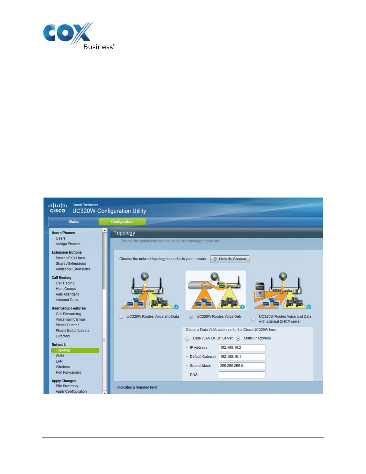
meaning the Cox E-SBC is connected to the UC320W WAN Ethernet port and routes only voice, i.e. SIP
Trunks.
Please refer to the network diagram in Figure 2 and the IP Address worksheet in Table 1 to cross
referen
For the Network Topology (Figure 5-1), input the following parameters:
Selec
Check “Static IP Address” for Obtain a Data VLAN address for the Cisco UC320W.
Enter the Data VLAN static IP Address assignment.
Enter the pre-existing router Default Gateway IP Address for Internet access.
Enter the Subnet Mask for your network.
Optionally, input a DNS server IP address.
siness currently supports the “UC320W Routes Voice Only” Network Topology configuration,
ce the example lab network IP addresses with your actual network values in the following screens.
t: “UC320W Routes Voice Only”
Figure 5-1 UC320 Routes Voice Only Network Topology
Property of Cox Communications, Inc. Version 1.0
Page 7 of 13
Page 8
5.2.2 WAN Network
In the “UC32
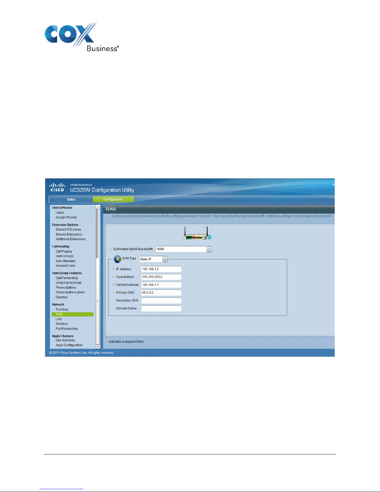
0W Routes Voice Only” network configuration, the UC320W WAN port is assigned in the
same subnet as the Cox E-SBC LAN IP address. The UC320W default gateway is set to the Cox E-SBC
LAN IP address.
For the Network Topology (Figure 5-2Figure 5-1), input the following parameters:
WAN
Type: Static IP
IP Address: <enter a static WAN IP address in same subnet as the Cox E-SBC>
Subnet Mask: <as appropriate for your network>
Default Gateway: <enter the Cox E-SBC static LAN IP Address as assigned for your network>
Primary DNS: <customer choice for DNS>
Domain Name: Leave blank.
The Cox E-SBC will insert the coxbusiness.com domain name in all outgoing SIP messages from the
UC320W.
Figure 5-2 Network WAN Internet Configuration
Property of Cox Communications, Inc. Version 1.0
Page 8 of 13
Page 9
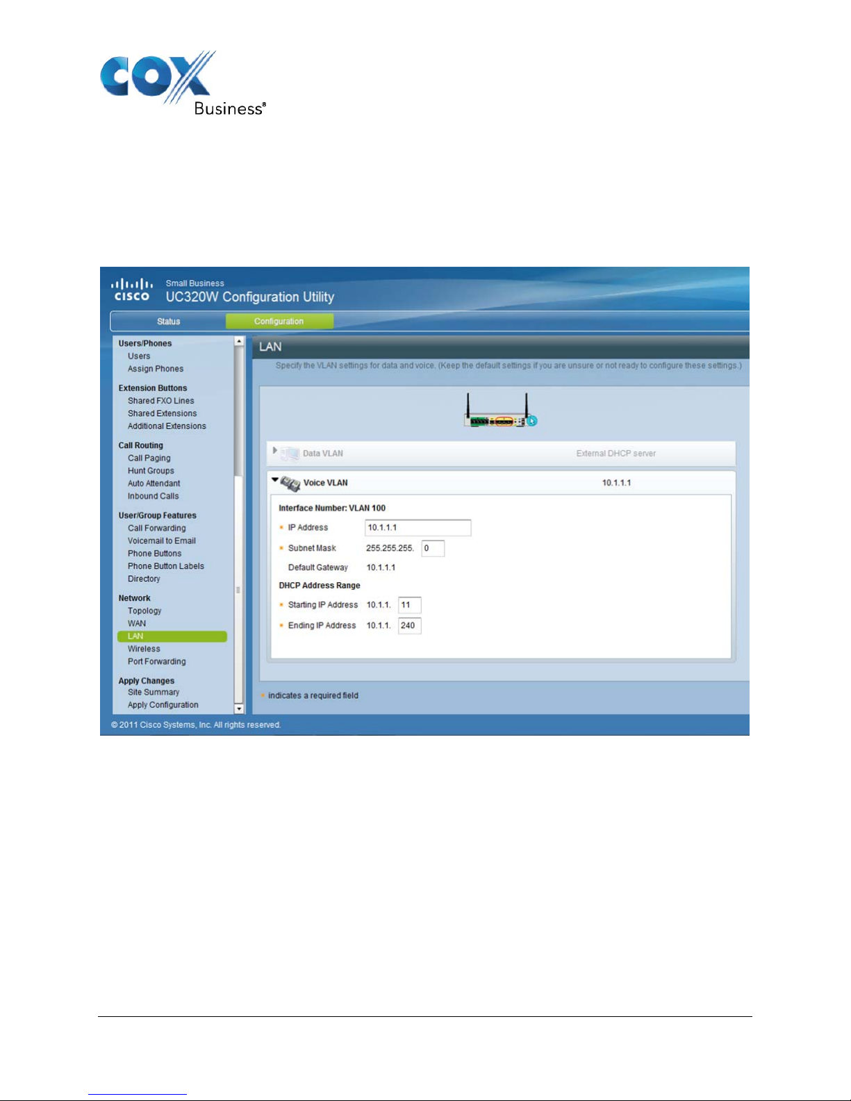
5.2.3 Voice VLAN
The Voice VLAN
setup is as follows. Note the UC320W is the DHCP server for assigning Voice VLAN IP
addresses to the IP Phones.
Enter the UC320W Voice VLAN IP Address and subnet mask for your network.
Enter the Voice VLAN DHCP Address range for your network.
5.2.4 UC320 Administrative Network Access
To acce
ss the UC320 from a personal computer for administrative access:
Manually assign a static LAN IP address to the PC in the same subnet as the UC320 WAN IP
address, for example, in the 192.168.10.X range.
Connect the PC with an Ethernet cable to a UC320 LAN port.
Open a web browser to the UC320 WAN IP address, e.g. 192.168.10.2.
Property of Cox Communications, Inc. Version 1.0
Page 9 of 13
Figure 5-3 Voice VLAN
Page 10
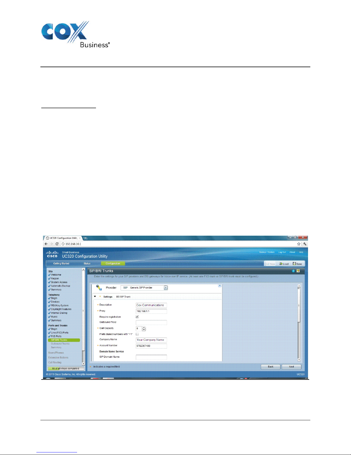
6 SIP Trunk Configuration
6.1.1
SIP Trunking configuration is performed using the UC320 Config uration Utility. You can enter the main parameters for
your Service Provider account on a "Generic SIP Provider". For further detail configurat ions of the UC320 refer the
UC3200 Admin Guide will provide guidance about SIP Trunks deployments and associated parameters. Figure
below shows an example of the UC320 Configuration Utility SIP Trunk Configuration Screen.
The following are the configuration parameters needed for SIP Trunking as illustrated in Figure 6-1 below:
SIP Trunking Configuration
1. Provider: Generic SIP Provider
2. Description: Cox Communications SIP Trunking
3. Proxy: 192.168.1.1
(Enter the LAN IP Address of the Cox E-SBC. Note your actual LAN IP may be different! Please
refer to the network diagram in Figure 2 and IP Address worksheet in Table 1.)
4. Regi
5. Outbound Proxy: <blank>
6. Call Capacity: <Enter the actual quantity of purchased SIP Trunk concurrent call sessions>
7. Prefix dialed numbers with "1": <blank> (uses National Numbering plan)
8. Company Name: <Your company name>
9. Account ID: <As provided by Cox Communications>
10. SIP Domain Name: <blank>
stration: Checked (Client-server SIP trunk, registration required)
(This will appear as the Display Name field on SIP messaging)
Note: The Cox E-SBC will automatically insert the “coxbusiness.com” domain name in all
outgoing SIP messages. Any value input here will be ignored by Cox.
Figure 6-1 SIP Trunking Configuration Parameters: 1 of 2
Page 10 of 13
Property of Cox Communications, Inc. Version 1.0
Page 11
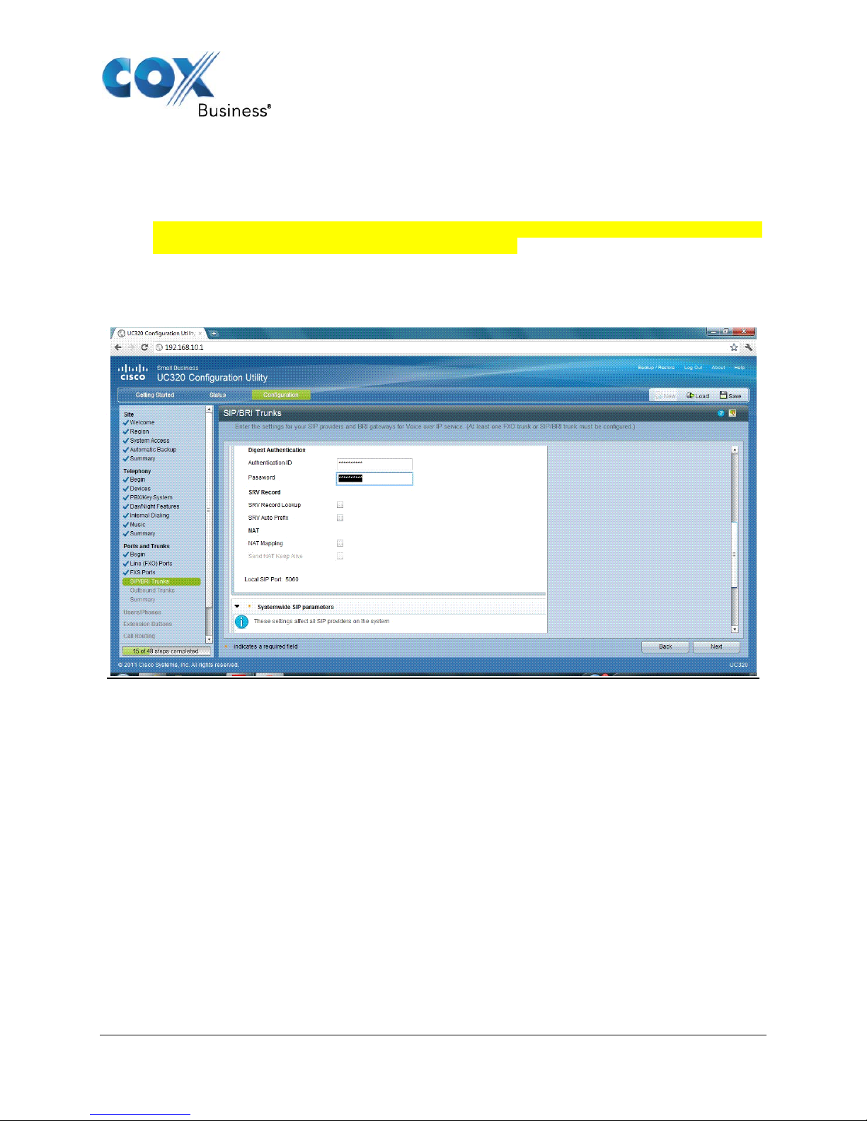
Please refer
to Figure 6-2 and enter the following parameters:
11. Authenticatio
n ID: <Enter the Trunk Group Pilot Number>
This is also known as the Main Directory Number for the customer account.
12. Password: <As provided by Cox Communications>
The SIP Authentication Password will be provided by your Cox Account Representation and must
be kept confidential. Cox will never ask for your password.
13. SRV Recorded Lookup: Uncheck
14. SRV Auto Prefix: Uncheck
15. NAT Mapping: Uncheck
Figure 6-2 SIP Trunking Configuration Parameters: 2 of 2
Systemwide SIP Parameters (refer to Figure 6-2 above):
16. Cod
ec: G711U
17. Outbound FAX: Passthrough
Property of Cox Communications, Inc. Version 1.0
Page 11 of 13
Page 12
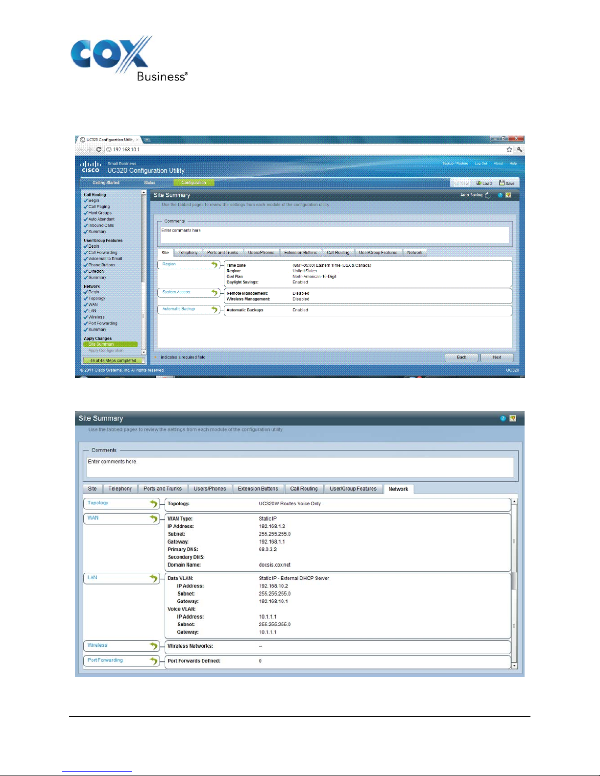
6.2 Cisco UC320 Apply Changes
The PBX settings can be reviewed on the Site Summary screen:
Network setting tab detail:
Figure 6-3 Site Summary
Property of Cox Communications, Inc. Version 1.0
Page 12 of 13
Figure 6-4 Network Summary Detail
Page 13
6.2.1 Adding and Removing Platform Modification Files
A
Platform Modification File (PMF) (https://supportforums.cisco.com/docs/DOC-16301
) is a Cisco
mechanism to override or modify certain internal UC320 configuration settings. The following PMF files
must be loaded into the Cisco UC320 for the system to work properly:
CallWaitingToneEnable_USA_CA.pmf
ChangeNTPserver.pmf
COX.pmf
The COX_UNDO.pmf is also available to undo the PMF file changes.
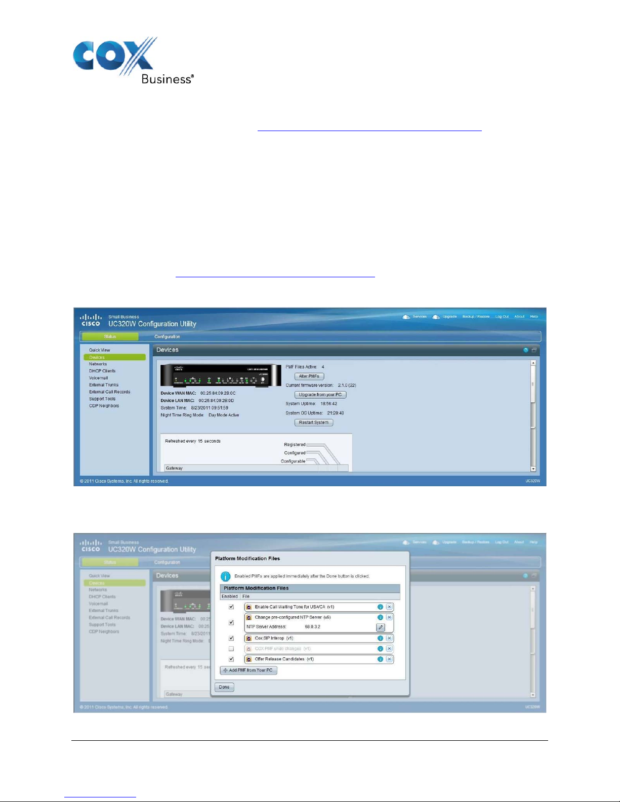
Do the following to apply the Cox PMF files to the UC320W:
1. Download the .pmf files for Cox Communications are from the Cisco UC320 Customized
Clearinghouse at http://www.ciscosbs2.com/movies/ucc/latest/
to your personal computer.
2. Navigate to the UC320W Status Devices screen.
3. Click the Alter PMFs button.
Figure 6-5 Devices: Upgrade PMF Files
Click the “Add PMF from Your PC” button to upload the .pmf files from your PC and verify each is
Enabled.
Figure 6-6 Platform Modification Files
Property of Cox Communications, Inc. Version 1.0
Page 13 of 13
 Loading...