

Page 1

Cox Business Internet Gateway
4131 User Guide
Page 2

© 2018 by Cox Communications.
All rights reserved. No part of this document may be reproduced or transmitted in any form or by any means, electronic,
mechanical, photocopying, recording, or otherwise, without prior written permissi on of Cox Communications . 0818
Page 3

Page 4

Table of Contents
Table of Contents
About this Setup and User Guide .................................................................................. 1
In this Setup and User Guide ...................................................................................... 1
Used symbols .............................................................................................................. 1
Getting Started ................................................................................................................ 2
Introduction .................................................................................................................. 2
Features at a Glance .................................................................................................... 2
Getting to Know the Gateway ..................................................................................... 3
Front Panel............................................................................................................... 3
Rear panel ................................................................................................................ 6
Bottom Panel ........................................................................................................... 7
Preparing for Installation ............................................................................................ 8
Wireless Connection ............................................................................................... 8
Wired Connection .................................................................................................... 8
Start with the Installation ........................................................................................ 8
Setup ............................................................................................................................... 9
Connect the Gateway to Your Service Provider’s Network ...................................... 9
Power on the Gateway ................................................................................................. 9
Connect Your Wired Devices .................................................................................... 10
Requirements ........................................................................................................ 10
Procedure .............................................................................................................. 10
Connect Your Wireless Devices ............................................................................... 11
How to Connect Your Wireless Client Via WPS ................................................... 11
How to Manually Connect Your Wireless Client .................................................. 13
How to Connect Your Phone ..................................................................................... 19
Admin Tool .................................................................................................................... 20
Requirements ............................................................................................................. 20
Accessing the Admin Tool ........................................................................................ 20
Admin Tool Menu ....................................................................................................... 21
How to Change the Default Admin Tool Password ................................................. 22
How to Backup or Restore a Configuration ............................................................. 22
iii
Page 5

Table of Contents
Gateway Wireless Access Point .................................................................................. 24
Wireless Access Point ............................................................................................... 24
Wireless Client ........................................................................................................... 24
Configuring Your Wireless Clients ....................................................................... 24
How to Configure the Wireless Settings .............................................................. 24
How to Set the Wireless Security ............................................................................. 27
How to S tart a WPS Session ..................................................................................... 28
Prevent Devices from Accessing Your Wireless Network ...................................... 29
MAC Address ......................................................................................................... 29
MAC Filtering ......................................................................................................... 29
Security Tab / Device Filter ................................................................................... 30
Enable Device Filter .............................................................................................. 30
Block All ................................................................................................................. 30
Allow All ................................................................................................................. 31
Options for Time of the Day Filters – When Block .............................................. 31
Internet Security ........................................................................................................... 32
Access Control .......................................................................................................... 32
Manage Sites and Devices ........................................................................................ 32
Security Tab / Access Control .............................................................................. 32
Blocked Sites ......................................................................................................... 33
Trusted Devices ..................................................................................................... 33
Manage Devices ......................................................................................................... 33
Security Tab / Device Filter ................................................................................... 33
Enable Device Filter .............................................................................................. 34
Block All ................................................................................................................. 34
Allow All ................................................................................................................. 34
Options for Time of the Day Filters – When Block .............................................. 34
Managed Services (Port Blocking) ........................................................................... 34
Security Tab / Service Filter .................................................................................. 35
Blocked Services ................................................................................................... 35
Trusted Devices ..................................................................................................... 35
Firewall ....................................................................................................................... 36
Changing the Security Level................................................................................. 38
Page 6

Table of Contents
Reports ....................................................................................................................... 39
Advanced Configuration .............................................................................................. 40
Port Configuration for Applications and Services................................................... 40
Issue ....................................................................................................................... 40
Solutions ................................................................................................................ 41
UPnP (Universal Plug and Play) ............................................................................... 41
Supported Operating Systems ............................................................................. 42
UPnP and the Gateway.......................................................................................... 42
How to use UPnP to Access Your Gateway on Windows 7/Vista ...................... 43
How to use UPnP to access your Gateway on Windows XP .............................. 43
Port Forwarding ......................................................................................................... 43
Use a Reserved IP Address .................................................................................. 43
Port triggering ............................................................................................................ 44
Port Filtering .............................................................................................................. 45
Configure a DMZ Host ............................................................................................... 46
Application Tab/DMZ ............................................................................................. 46
Dynamic DNS ............................................................................................................. 47
Assigning a Reserved IP (static IP) to a Device ....................................................... 48
Support .......................................................................................................................... 50
Wireless Connection Troubleshooting ..................................................................... 50
No Wireless Connectivity ...................................................................................... 50
Poor Wireless Connectivity or Range .................................................................. 50
Change the Wireless Channel .............................................................................. 51
Make Sure That the Wireless Access Point Is Enabled ...................................... 51
Cannot Connect via WPS ...................................................................................... 52
Network Diagnostic Tools ......................................................................................... 52
Gateway Reboot and Reset Options ........................................................................ 54
Reset/Restore the Gateway via the Reset Button ............................................... 55
Page 7
About this Setup and User Guide
About this Setup and User Guide
In this Setup and User Guide
The goal of this Setup and User Guide is to:
• Set up your Gateway and local network
• Configure and use the main features of your Gateway
• Configure Internet Security
Used symbols
Danger: The danger symbol indicates there may be a possibility of physical injury.
Caution: The caution symbol indicates there may be a possibility of equipment
damage. It can also mean that there may be a possibility of service interruption
Important: The important symbol indicates a required or recommended step or
component.
Note: The note symbol indicates that the text provides additional information about
a topic.
CGA4131 Business Gateway Setup and User Guide 1
Page 8

Getting Started
Getting Started
Introduction
This chapter provides a brief overview of the main features and components of the Gateway.
After this chapter, we will start with the installation.
Danger: Do not connect any cables to the Gateway until instructed to do so.
Features at a Glance
The Technicolor CGA4131 offers the following features:
• Compliance with DOCSIS 3.0 and 3.1 standards to deliver high-end performance and
reliability
• High performance Broadband Internet Connectivity
• Eight-line embedded digital voice adapter for wired telephony or fax service
• Two 802.11 Wi-Fi radios for dual-band concurrent operation, with up to eight SSIDs per
radio
• Eight IEEE 802.3 10/100/1000 Base-T Gigabit Ethernet LAN ports
• Wi-Fi Protected Setup™ (WPS) support with hardware push button for simplified and
secure wireless setup
• User configurable access control and firewall settings
• Compact design allows for horizontal or wall-mounted operation
• Color coded interface ports and corresponding cables to simplify installation and setup
• Front panel LEDs show operational status
• Optional battery backup with 8 hours standby and 5 hours talk time.
• IPv6 DS-Lite enabled
CGA4131 Business Gateway Setup and User Guide 2
Page 9
Getting Started
Getting to Know the Gateway
This section introduces you to the different components of the Gateway.
Front Panel
Front Panel View and LED Operations
The following images represent the front panel view of the CGA4131.
Figure 1: Front Panel
Figure 2: Front Panel with LEDs
CGA4131 Business Gateway Setup and User Guide 3
Page 10
Getting Started
Ethernet LED (Item A)
State Description
Solid on Ethernet is enabled with AC power
Off Ethernet is not enabled
Ethernet Ports 1-8 LEDs (Items B – I)
The CGA4131 has 8 Ethernet ports. The status of each port is shown by its LED state.
Port 1 LED B Port 2 LED C Port 3 LED D Port 4 LED E
Port 5 LED F Port 6 LED G Port 7 LED H Port 8 LED I
State Description
Solid on The port is connected.
Off The port is not connected
Blinking Data is being transferred
Internet LED (Item J)
State Description
Solid on Internet Service is active
Off There is no Internet Service
Wi-Fi LED (Item K)
State Description
Blinking Data (2.4GHz or 5GHz) is active over the wireless connection
Off Wi-Fi access point is not enabled
Online LED (Item L)
State Description
Solid on
Blinking Trying to acquire Upstream, Downstream frequencies
Connected to the service provider’s network. Even when Internet is not active, LED
is on. Data traffic can be used.
CGA4131 Business Gateway Setup and User Guide 4
Page 11
Getting Started
Line 1
Line 2
Line 3
Line 4
Line 5
Line 6
Line 7
Line 8
Telephone Lines 1-8 LEDs (Items M – T)
The CGA4131 has 8 telephone lines. The status of each telephone line is shown by its LED
state.
Telephone
Telephone
LED M
LED Q
Telephone
Telephone
LED N
LED R
Telephone
Telephone
LED O
LED S
Telephone
Telephone
LED P
LED T
State Description
Solid on Telephone line is registered successfully with the call manager
Blinking Telephone line has either gone off-hook or is in active call
Off Telephone line is not registered with the call manager
Reset Button (Item U)
Press the Reset button to reset the box. Press the Reset button approximately 12-13 seconds
to restore to factory settings.
For more information, see Reset/Restore the Gateway via the Reset Button.
Telephone Line LED (Item V)
State Description
Solid on
MTA Voice interface is operational
Off
MTA Voice interface is not operational
WPS (Item W)
The LED blinks when the WPS button is pressed. It will blink for 2 minutes or until the wireless
client Wi-Fi is connected to the gateway, whichever is earlier. The LED will then turn solid
white for 2 minutes and will turn Off thereafter.
For more information about WPS, see How to Connect Your Wireless Client Via WPS.
State Description
Blinking WPS Process initialized (lasts for 2 minutes)
Off No WPS activity
CGA4131 Business Gateway Setup and User Guide 5
Page 12
Getting Started
Battery LED (Item X )
State Description
Off Device is off, or AC power is on or Battery is not installed
Solid on On Battery Power
Blinking Battery needs replacement
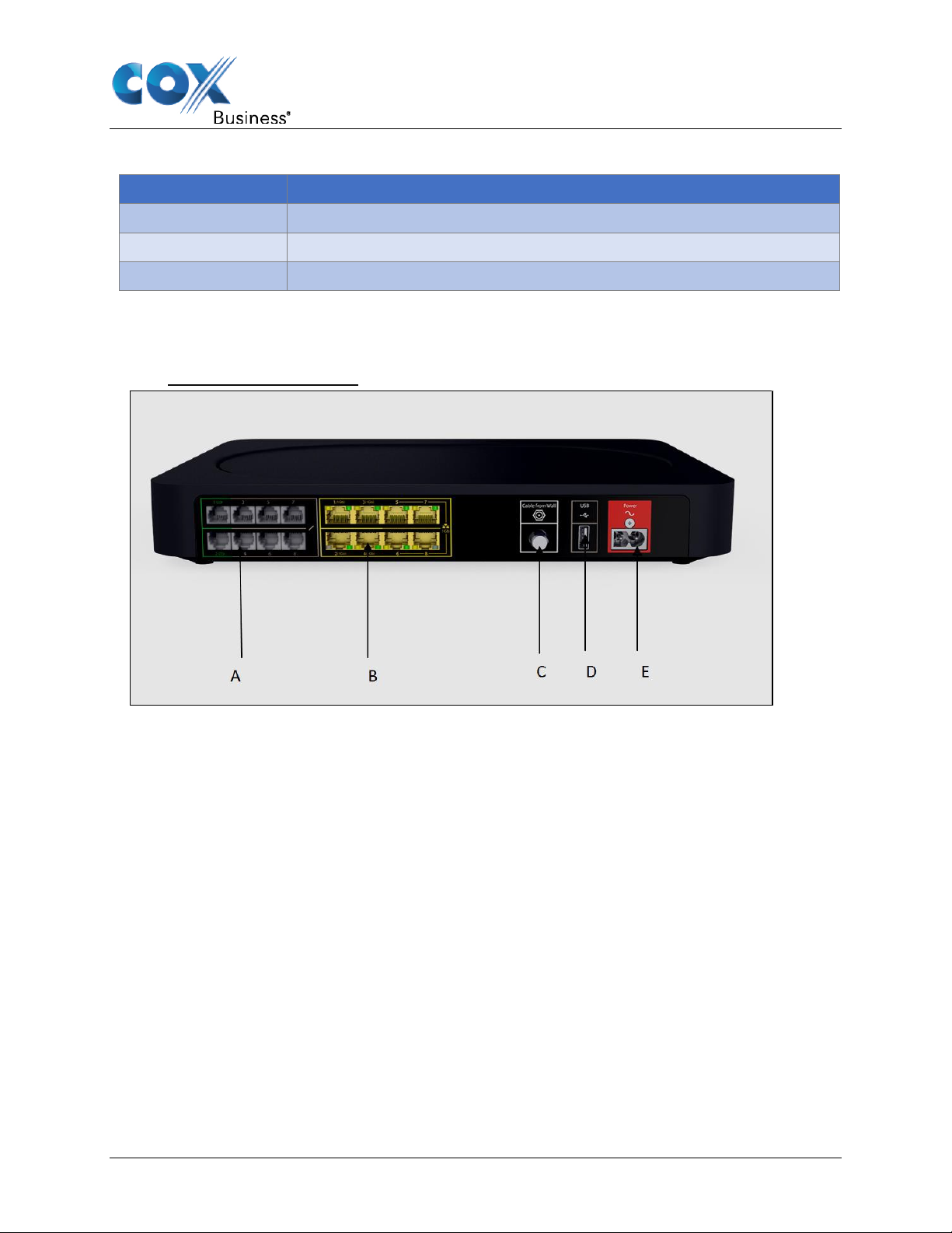
Rear panel
The following image shows the back-panel view of the CGA4131.
Figure 3: Rear Panel View
Telephone port (Item A)
The CGA4131 supports up to eight traditional phones or DECT base station to connect to the
Gateway. Single-line customers can use the Tel 2/Alarm port to connect an auto dial alarm
system.
For more information, see
CGA4131 Business Gateway Setup and User Guide 6
Page 13
Getting Started
How to Connect Your Phone.
Ethernet switch (Ite m B)
The CGA4131 supports up to eight Ethernet connections (for example, a computer) to your
local network. For more information, see Connect Your Wired Devices.
The first 4 Ethernet ports each can transfer up to 1 Gbps data, while ports 5 to 8 can have a
combined data transfer speed of 1 Gbps.
Each Ethernet port has two LEDs:
LED LED Status Description
Left LED
(Green)
Right LED
(Amber)
Solid on Connected to a Gigabit Ethernet device
Blinking Connected to a Gigabit Ethernet device and sending/receiving data
Off Not connected to a Gigabit Ethernet device
Solid on Connected to a100Mbps/10Mbps device
Blinking Connected to a 100Mbps/10Mbps device and sending/receiving data
Off Not connected to a 100Mbps/10Mbps device
Cable Port (Item C)
The CGA4131 complies with DOCSIS 3.0 and 3.1 standards along with PacketCable™
specifications to deliver high-end performance and reliability.
USB Port (Item D)
USB port is used to connect USB devices.
Power Inlet (Item E)
The power cord is connected here (Power).
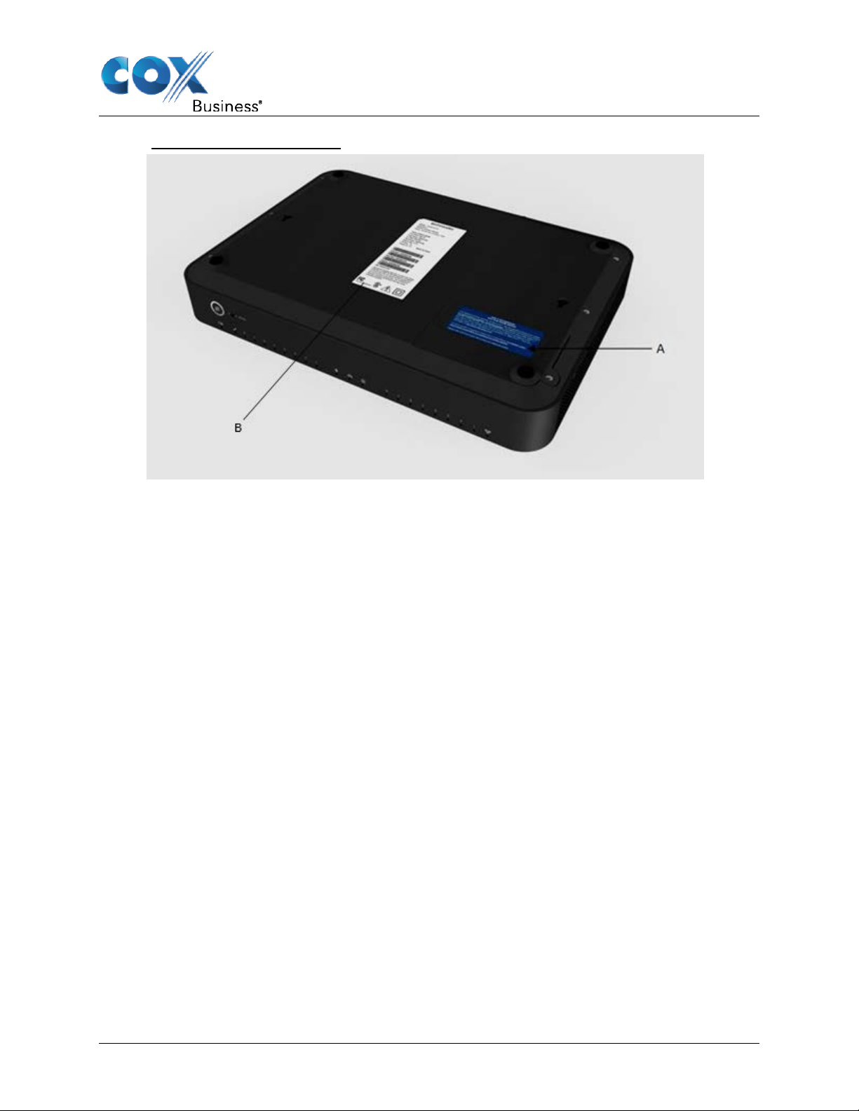
Bottom Panel
Figure 4 shows the CGA4131 bottom panel and Battery Compartment with door on (Item A).
Battery Slot (Optional ) (Item A)
During a power failure, the Gateway can automatically switch to the auxiliary emergency power
through the rechargeable battery (if installed). The following capabilities are supported during a
loss of power:
• The connected phones or dial function for a connected alarm system
• Basic voice features.
Danger: Do not remove the battery unless instructed by your service provider.
CGA4131 Business Gateway Setup and User Guide 7
Page 14
Getting Started
Figure 4: Bottom Panel View
Product Label (Item B)
Setup information, including the Gateway SSID, Passphrase, MAC addresses and Serial
Number can be found here.
Preparing for Installation
Wireless Connection
If you want to connect your computer using a wireless connection, your computer must be
equipped with a Wi-Fi Certified wireless client adapter.
Wired Connection
If you want to connect a computer using a wired connection, your computer must be equipped
with an Ethernet Network Interface Card (NIC).
Start with the Installation
You are now ready to start with the installation of your Gateway.
CGA4131 Business Gateway Setup and User Guide 8
Page 15
Setup
Setup
Complete the following to set up the Gateway:
• Connect your Gateway to your service provider’s network. For more information, see
Connect the Gateway to Your Service Provider’s Network.
• Power on the Gateway. For more information, see Power on the Gateway.
• Connect your wired devices to the Gateway. For more information, see Connect Your
Wired Devices.
• Connect your wireless devices to the Gateway. For more information, see Connect Your
Wireless Devices.
• Connect your phones. For more information, see How to Connect Your Phone.
After completing the setup procedure, the Gateway is ready for use. Optionally, you can further
configure the Gateway to your needs (for example, change the wireless security) using the
Gateway’s Admin Tool. For more information, see Admin Tool.
Connect the Gateway to Your Service Provider’s Network
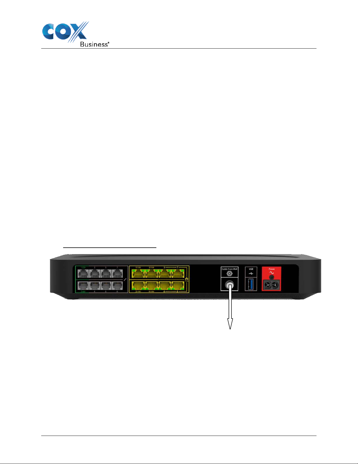
This section helps you connect the Gateway to your service provider’s network.
1. Take one end of the coaxial cable and connect it to the cable splitter.
2. Connect the other end to the Cable port of the Gateway.
Figure 5: Back Panel – Cable Port
Cable
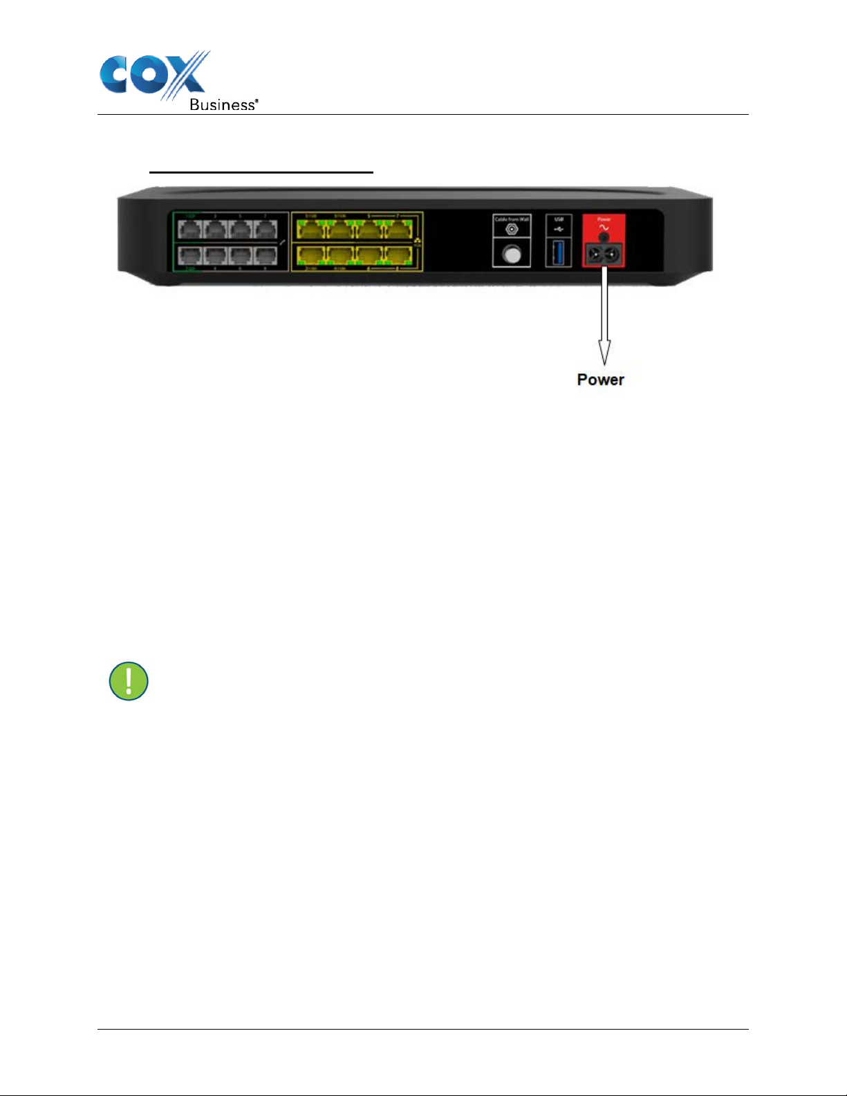
Power on the Gateway
Proceed as follows:
1. Use the power cord that is included with your Gateway.
2. Connect the small end of the power cord to the Power port on the back of the Gateway
(see Figure 6).
3. Plug the other end of the power cord into an electrical outlet.
CGA4131 Business Gateway Setup and User Guide 9
Page 16
Setup
4. Wait at least two minutes to allow the Gateway to complete the startup phase.
Figure 6: Back Panel – Power Port
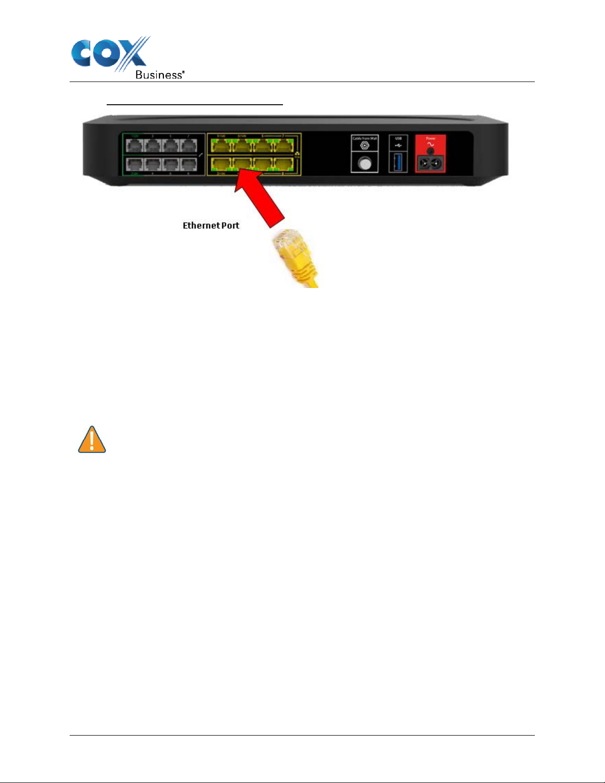
Connect Your Wired Devices
All Ethernet ports on the Gateway are Gigabit Ethernet ports and have a maximum speed of 1
Gbps (gigabit per s econd).
Requirements
• Both your network device (for example, a computer, a point of sale terminal, etc.) and
Gateway must have a free Ethernet port.
• Your network device must be configured to obtain an IP address automatically. This is
the default setting.
Procedure
Important: It is recommended to use Category 5e or Category 6 Ethernet cables
with the Gateway.
1. lug one end of the Ethernet cable into one of the RJ-45 Ethernet ports on the back of the
Gateway (see Figure 7).
2. Plug the other end of the Ethernet cable into the Ethernet port of your network device.
3. Your network device is now connected to your network. Use the same procedure to
connect other Ethernet devices (computers, network printers and so on).
CGA4131 Business Gateway Setup and User Guide 10
Page 17
Setup
Figure 7: Back Panel – Ethernet Ports
Connect Your Wireless Devices
The Gateway has two access points that allow you to connect wireless devices to your
network:
• The 5 GHz IEEE 802.11a/n/ac access point offers superior transfer rates, is less
sensitive to interference and allows you to connect IEEE 802.11a/n/ac wireless clients.
• The 2.4 GHz IEEE 802.11b/g/n access point allows you to connect IEEE 802.11b/g/n
wireless clients. Use this acces s point for wireless clients that do not support 5 GHz.
Caution: If you want to connect your wireless client to the 5 GHz access point,
make sure that your wireless client supports 5 GHz connections.
To connect your device:
• Using the Wi-Fi Protected Setup (WPS), proceed with How to Connect Your Wireless
Client Via WPS.
• By manually entering the settings, proceed with How to Manually Connect Your Wireless
Client.
How to Connect Your Wireless Client Via WPS
Wi-Fi Protected Setup (WPS) allows you to add new wireless clients to your local network in a
swift and easy way, without the need to enter any of your wireless settings (network name,
wireless network key, encryption type).
Both the 2.4 GHz as the 5 GHz access points of your Gateway support WPS.
CGA4131 Business Gateway Setup and User Guide 11
Page 18
Setup
Requirements
• Your wireless client must support WPS. Check the documentation of your wireless client
for this.
• Your Gateway must use WPA/WPA2-PSK (TKIP/AES) encryption (default encryption) or
WPA2-PSK ( AES) en cryption.
WPS methods
The following WPS methods are supported by your Gateway:
• Push Button Configuration (PBC): Place both the wireless client and the Gateway in
registration mode by pushing a hardware or software button.
• PIN code entry on the wireless client: Enter the Gateway’s WPS PIN code on the
wireless client. For more information, see How to Start a WPS Session.
• PIN code entry on the Gateway: Enter the wireless client’s WPS PIN code on the
Admin Tool. For more information, see How to Start a WPS Session.
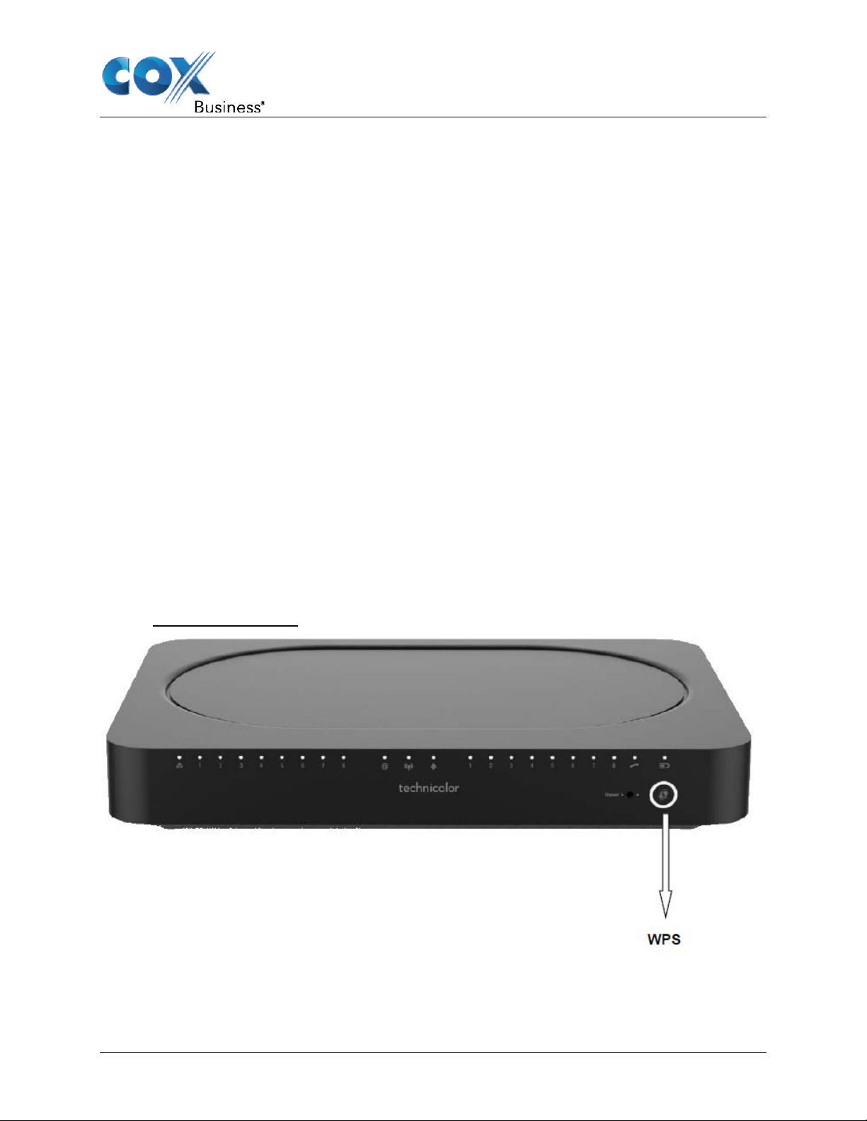
Procedure for PBC
Proceed as follows:
1. Start WPS on your wireless client.
2. On the Gateway, press and hold the WPS button for at least 5 seconds and then release
it.
Result: The WPS button LED will start blinking. This indicates that the Gateway is now
searching for wireless clients that are in registration mode.
Figure 8: WPS Button
The Gateway is now exchanging the security settings with the wireless client. Your wireless
client will prompt you when it is connected to the access point.
CGA4131 Business Gateway Setup and User Guide 12
Page 19

Setup
Troubleshooting
If you are having trouble connecting your wireless client via WPS, this may be caused by one
of the following reasons:
• WPS cannot be correctly executed: Configure your wireless manually. For more
information, see How to Manually Connect Your Wireless Client.
• Your wireless client is out of range: If possible, move your wireless client closer to your
Gateway or use a wireless repeater to extend the range of your wireless network.
How to Manually Connect Your Wireless Client
Requirements
• Your network device must be equipped with a Wi-Fi Certified wireless client.
• Your network device must be configured to obtain an IP address automatically. This is
the default setting.
Procedure
If you want to connect a computer using the wireless network, configure the wireless client on
your computer with the wireless settings printed on the Gateway's back panel label.
The Gateway’s back panel contains two items needed to establish a Wi-Fi connection:
• SSID (“Network Name”) is the name of the network. Either the 2.4GHz or 5GHz network
name can be used.
• Passphrase is the password used for the network name selected.
To configure these settings on:
• Windows 10, proceed with How to Connect Your Computer on Windows 10.
• Windows 8, proceed with How to Connect Your Computer on Windows 8.
• Windows 7, proceed with How to Connect Your Computer on Windows 7.
• Windows Vista, proceed with How to Connect Your Computer on Windows Vista.
• Windows XP, proceed with How to Connect Your Computer on Windows XP
• Mac OS X, proceed with How to Connect Your Computer on Mac OS X.
• On another operating system, consult the help of your wireless client or operating
system.
CGA4131 Business Gateway Setup and User Guide 13
Page 20

Setup
How to Connect Your Computer on Windows 10
Proceed as follows:
1. Click the wireless network icon ( ) in the notification area.
Result: A list of available wireless networks appears.
Figure 9: Available Wireless Networks
2. Double-click the Gateway’s Network Name (SSID). Use the Gateway’s Network Name
(SSID) as printed on the bottom panel label. For more information, see Bottom Panel.
Result: Windows prompts you to enter the security key (see Figure 10).
3. Type the Passphrase from the Gateway's bottom panel label in the Enter the network
security key box and click Next.
Result: Windows prompts you if it should turn on sharing.
Figure 10: Enter Network Security Key
4. Click Yes to turn on sharing.
How to Connect Your Computer on Windows 8
Proceed as follows:
1. Click the wireless network icon ( ) in the notification area.
Result: A list of available wireless networks appears (see Figure 9).
CGA4131 Business Gateway Setup and User Guide 14
Page 21

Setup
2. Double-click the Gateway’s Network Name (SSID). Use the Gateway Network Name as
listed on the Gateway's back panel label.
Result: Windows prompts you to enter the security key (see Figure 10).
3. Type the Passphrase from the Gateway's bottom panel label in the Enter the network
security key box and click Next.
Result: Windows prompts you if it should turn on sharing.
4. Click Yes to turn on sharing.
How to Connect Your Computer on Windows 7
Proceed as follows:
1. Click the wireless network icon ( ) in the notification area.
2. A list of available wireless networks appears.
3. Type the network key, which is printed on the Gateway's bottom panel label in the
Security key box and click OK.
Figure 11: Enter Network Key - Windows 7
CGA4131 Business Gateway Setup and User Guide 15
Page 22

Setup
How to Connect Your Computer on Windows Vista
Proceed as follows:
1. Click Start ( ) and then click Connect To.
Result: A list of available wireless networks appears.
Figure 12: Available Wireless Networks - Windows Vista
2. Double-click the Gateway’s Network Name (SSID). The Gateway’s Network Name (SSID)
is listed on the Gateway's back panel label.
Result: Windows prompts you to enter the network security key.
3. Type the Passphrase from the Gateway's back panel label in the Security key or
passphrase box and click Connect.
Figure 13: Enter Network Key - Windows Vista
CGA4131 Business Gateway Setup and User Guide 16
Page 23

Setup
How to Connect Your Computer on Windows XP
Proceed as follows:
1. Right-click the wireless network connection icon ( ) in the notification area and then click
View Available Wireless Networks.
Result: A list of available wireless networks appears.
Figure 14: Available Wireless Networks – Windows XP
2. Double-click the Gateway’s Network Name (SSID) access point. The Gateway’s Network
Name (SSID) is listed on the Gateway's back panel label. For more information, see
Bottom Panel.
Result: Windows prompts you to enter the network security key.
3. Type the Passphrase, which is printed on the Gateway's bottom panel label, in the
Network key and Confirm network key boxes and then click Connect.
Result: You are now connected to the Gateway:
Figure 15: Enter Network Key - Windows XP
How to Connect Your Computer on Mac OS X
Proceed as follows:
1. Click the Wi-Fi icon on the menu bar.
Result: A list of available wireless networks appears.
CGA4131 Business Gateway Setup and User Guide 17
Page 24

Setup
Figure 16: Available Wireless Networks
2. Double-click the Gateway’ Network Name (SSID). The Gateway’s Network Name (SSID)
is printed on the Gateway's side or back panel label.
Result: The Wi-Fi window prompts you to enter your WPA password.
Figure 17: Enter WPA Password
3. In the Password box, type the Passphrase, which is printed on the Gateway's bottom
panel label.
4. Select the Remember this network checkbox and click OK.
Result: You are now connected to the Gateway network.
CGA4131 Business Gateway Setup and User Guide 18
Page 25

Setup
How to Connect Your Phone
This section describes how to connect phones for single line customers.
Important: If you have a two-line setup or a setup involving an alarm, please
contact your service provider. This setup must be done by qualified technicians.
1. Connect your traditional phone, external DECT base station or fax to an active RJ-11
Telephone jack on the back panel of your Gateway.
Figure 18: Telephone Ports
Note: You must connect Alarms dialers to either port 1 or 2. Be sure the Alarms
dialer is connected to an active telephone port connected to the phone network.
2. Plug the other end of the telephone cable into the telephone device.
3. Verify that each phone line is active by first checking for dial tone, and then by placing a
call to an active telephone number and checking that both parties can properly hear one
another.
CGA4131 Business Gateway Setup and User Guide 19
Page 26

Admin Tool
Admin Tool
The Admin Tool allows you to configure the settings of your Gateway through your web
browser, using a computer or device that is currently connected to your Gateway (either wired
or wirelessly).
Note: The Admin Tool web pages are displayed differently for smaller screens if
you connect using a mobile device. The example in this guide shows the screens
as accessed using a computer.
Requirements
JavaScript must be enabled on your browser (this is the default setting). For more information,
consult the help of your web browser.
Accessing the Admi n To ol
Proceed as follows:
1. Open your web browser and go to http://192.168.0.1, using a computer or device that is
currently connected to your Gateway (either wired or wirelessly).
On Windows, it is also possible to access the Admin Tool using UPnP. For more
information, see UPnP (Universal Plug and Play).
Note: 192.168.0.1 is the default IP address of the Gateway. If at some point you
changed the IP address of the Gateway, use the new IP address instead.
2. The Gateway prompts you to enter the username and password. Enter your user name
(default: blank) and password (default: blank).
Result: The Admin Tool appears.
Figure 19: Admin Tool
CGA4131 Business Gateway Setup and User Guide 20
Page 27

Admin Tool
Overview
s provide basic information about the
information on the Local Network, the
Gateway
Local Network
Wireless
DOCSIS Status
DOCSIS Signal
DOCSIS Log
Spectrum Analyzer
System
Devices
LAN
WAN
Routing
Modem
MTA
Network Time
Radio
Security
Advanced
Guest Network
MAC Control
WPS
QoS
Hotspot
Firewall
IP Filter
Device Filter
Access Control
Service Filter
VPN
Email Settings
Report
Application
Port Forward
Port Trigger
Port Filter
DDNS
DMZ
UPnP
IP Passthrough
SIP ALG
Admin Tool Menu
The Admin Tool menu consists of the following first-level menu items. Based on your service
provider’s network, some screens listed in the “Sub Menu” column may not be available to you.
Top Level Menu Sub Menus Description
Status
Connection
Wireless
Security
The Status screen
Gateway, including
Wireless Networks, and the DOCSIS Network to your Service
Provider.
The Connection screens show devices that are connected to your
gateway on various Local Networks provided by your Gateway as
well as options to enable Bridge Mode Routing. There are also
options to configure your Gateway using a Static IP address.
The Wireless screens show options related to the wireless
network, including radio parameters and wireless security.
The Security screens provide options to manage and filter
Internet access provided by the Gateway.
CGA4131 Business Gateway Setup and User Guide 21
Options related to Port Forwarding and other features are
found in the Application menu.
Page 28

Admin Tool
User
Remote Access
Backup & Restore
Reboot & Reset
Troubleshooting
Remote Log
System
Interface
Network
Wireless
Clients
Internet
Top Level Menu Sub Menus Description
Administration
Diagnostic
The Administration screens present options to change the user
name and password, add users, and reset the device.
Diagnostic screens provide some utilities to troubleshoot your
network connection or Gateway.
How to Change the Default Admin Tool Password
We recommend changing the default password of the Gateway the first time it is used. The
username and password fields are em pty by default.
1. Go to the Admin Tool (http://192.168.0.1) using a computer or device that is currently
connected to your Gateway (either wired or wirelessly). For more information, see
Accessing the Admin Tool.
2. Enter the default username and password.
3. A pop-up message displays, prompting you to change the password.
How to Backup or Restore a Configuration
The backup feature saves the current Gateway configuration to a local PC. These settings can
be restored later if a configuration needs to be restored, or to recover from changes that have
had an undesirable effect.
To back up the current configuration, click Administration on the Admin Tool menu, and then
click Backup on the sub-menu. Follow the onscreen instructions.
Figure 20: Backup and Restore Options
CGA4131 Business Gateway Setup and User Guide 22
Page 29

Admin Tool
To restore a previous configuration, click Browse and use the navigation window to locate the
file. The default file name is in the following format:
filename_YY_MM_DD_HOUR_MINUTES.gwc.
When the file has been located, click Restore to restore the settings. When the settings are
restored, the device will reboot to the restored settings.
Important: Do not edit the backup files; this may result in corrupt files making
them worthless as configuration backup.
Caution: Restoring a saved configuration will require the Gateway to restart. The
reboot will cause a short service interruption of the services provided by the
Gateway.
CGA4131 Business Gateway Setup and User Guide 23
Page 30

Gateway Wireless Access Point
Gateway Wireless Access Point
This section will help you set up your wireless network. To set up a wireless network, you need
the following components:
• Wireless access point (already integrated into your gateway)
• Wireless client (for example, a computer, smartphone, network printer)
Wireless Access Point
The wireless access point is the heart of your wireless network. The wireless access point:
• Connects different wireless clients
• Secures the data sent over wireless connection
The Gateway has two access points:
• The 5 GHz access point enables superior transfer rates for 802.11a/n/ac wireless devices
that are closer to the AP.
• The 2.4 GHz access point provides connectivity to 802.11b/g/n wireless clients that are
farther from the AP. Use this access point for legacy wireless clients.
Note: If you are connecting the wireless client to the 5 GHz access point, make
sure the wireless client supports 5 GHz connections.
Wireless Client
The wireless client allows you to connect a wireless client to a wireless access point. Both
built-in and external (for example via USB) wireless clients are available.
Devices like tablets, smart TVs and smartphones usually have a built-in wireless client. Check
the documentation of your device for more information.
Configuring Your Wireless Clients
For more information on how to establish a wireless connection to the Gateway, see:
• How to Connect Your Wireless Client Via WPS
• How to Manually Connect Your Wireless Client
How to Configure the Wireless Settings
1. Go to the Admin Tool (http://192.168.0.1) using a computer or device that is currently
connected to your Gateway (either wired or wirelessly). For more information, see
Accessing the Admin Tool.
2. Click the Wireless tab then click the Radio sub-tab.
Result: The screen displays Radio setup information at 2.4GHz and 5GHz:
CGA4131 Business Gateway Setup and User Guide 24
Page 31

Or
Gateway Wireless Access Point
Figure 21: Wireless – Radio Settings
The following fields are available for configuration:
Wireless Interface: The wireless interface can be enabled or disabled with this option.
Network Name: The Network Name (SSID) can either be set or displayed under this option.
The user can also prevent the network name (SSID) from being broadcast by selecting the
“hide” option.
Network Mode: The Network Mode determines which 802.11 wireless protocols will be used.
The Network Mode has different options available according to the wireless interface:
For 2.4GHz:
CGA4131 Business Gateway Setup and User Guide 25
Page 32

Gateway Wireless Access Point
• 802.11b only
• 802.11g only
• 802.11n only
• Mixed (802.11b and 802.11g)
• Mixed (802.11g and 802.11n)
• Mixed (802.11b, 802.11g and 802.11n)
For 5GHz:
• 802.11a only
• 802.11n only
• 802.11ac only
• Mixed (802.11a and 802.11n)
• Mixed (802.11n and 802.11ac)
• Mixed (802.11a, 802.11n and 802.11ac).
Channel Width:
The channel bandwidth can be selected manually for Wireless-N connections. For best
performance in a network using Wireless-N, Wireless-G, and Wireless-B devices, it is
suggested to use the AUTO (20 or 40MHz) channel setting.
Wireless-N connections will use the 40MHz channel if there is no interference, while WirelessG and Wireless-B will still use the 20MHz channel.
For Wireless-G and Wireless-B networking only, select 20MHz only. Then, only the 20MHz
channel will be used.
For 5GHz, the options include AUTO 20 or 40 or 80MHz. The 80MHz will only be used for AC.
Channel:
If AUTO (20 or 40MHz) is selected for the Radio Band setting the appropriate Standard
Channel setting will be automatically selected, depending on the Wide Channel setting.
If only 20MHz is selected as the Radio Band setting, select the appropriate channel from the
list provided to correspond with the network settings. All devices in the wireless network must
broadcast on the same channel to communicate.
MAC Address: The wireless MAC Address is displayed in this field.
Scan Nearby AP: The Scan button provides a mechanism for the AP to scan for neighboring
APs and provides various statistics on neighbors.
Note: Enabling Network Name (SSID) broadcast does not mean that everyone
can connect to your network. They still need the correct wireless network key
(password) to connect to the Gateway network. It only informs them that your
network is present.
CGA4131 Business Gateway Setup and User Guide 26
Page 33

Gateway Wireless Access Point
Important: Network Name (SSID) broadcasting is required for WPS.
How to Set the Wireless Security
It’s recommended to set a password on the Wi-Fi networks you set up.
1. Go to the Admin Tool (http://192.168.0.1) using a computer or device that is currently
connected to your Gateway (either wired or wirelessly). For more information, see
Accessing the Admin Tool.
2. Click the Wireless tab then click the Security sub-tab. Here, you can set and display
Wireless Network (2.4GHz and 5GHz) security information including the Network Name,
Security Mode, Encryption, Network Password, and Key Interval.
Figure 22: Wireless Security Settings
Available settings include:
Network Name: The Network Name is displayed here.
Security Mode: Options for security settings include:
• 2.4GHz: Open, WPA2 Personal, WPA or WPA2 Personal
• 5GHz: Open, WPA2 Personal, WPA or WPA2 Personal
The default setting is WPA or WPA2 Personal.
Encryption: For ease of use, the encryption mode changes according to the selected security
mode. For example: If the security mode is selected to be “WPA2 Personal”, the selected
encryption mode will be AES. Similarly, if the security mode being used is WPA or WPA2
Personal, the encryption mode will be AES and TKIP.
Network Password: You must select a password that meets the requirements of the
encryption type being used:
CGA4131 Business Gateway Setup and User Guide 27
Page 34

Gateway Wireless Access Point
• Open: No password needed
• WPA2 Personal: at least 8 characters
• WPA or WPA2 Personal: at least 8 characters
Key Interval: The default is 3600 seconds.
Be sure to click the Save button at the bottom of the screen after making any changes.
How to Start a WPS Session
Wi-Fi Protected Setup (WPS) allows users to easily connect to the wireless network by simply
pushing a button or entering a PIN code. WPS permits home users to easily connect to a
secure network without any complex configuration and eliminates the need to remember or
store their security information in an unsafe way.
The CGA4131 supports the WPS Push-Button Configuration (PBC). In this method, the user
pushes a button, either an actual or a virtual one, on both the access point and the new
wireless client device.
The CGA4131 provides two WPS PBC buttons:
• Hardware button on the front panel
• Software button on the Web UI
Pressing either PBC button on the CGA4131 will flash the WPS LED and initiate the WPS PBC
operation. Then, press the software PBC button on the client device (some clients use a
hardware button). The two buttons must be pushed within 60 seconds of each other.
Using the Admin Tool, click the Wireless tab and then click the WPS control tab. The screen
displays WPS setup information. Here a user can set and display WPS parameters including
the Access Point PIN and Connection Method (Push Button / PIN Number).
CGA4131 Business Gateway Setup and User Guide 28
Page 35

Gateway Wireless Access Point
Figure 23: WPS Settings
Prevent Devic es fr om Accessing Your Wirele ss N etwork
MAC Address
A MAC (Media Access Control) address is a unique hexadecimal code that identifies a device
on a network. Each network-enabled device has at least one unique MAC address.
For example, if your computer is equipped with an Ethernet and a wireless network adaptor,
each of these interfaces will have its own MAC address.
MAC Filtering
When using MAC filtering, you allow or deny devices to access your network based on their
MAC address.
1. Go to the Admin Tool (http://192.168.0.1), using a computer or device that is currently
connected to your Gateway (either wired or wirelessly). For more information, see
Accessing the Admin Tool.
2. Click the Security tab then click the Device Filter tab.
Result: The Device Filter settings screen displays.
CGA4131 Business Gateway Setup and User Guide 29
Page 36

Gateway Wireless Access Point
Figure 24: Device Filter Settings
The Device Filter screen is used to allow or block devices connecting to the router, for both
LAN and Wi-Fi clients. The devices are allowed or blocked with respect to their MAC address,
which is added in the allowed devices list in this screen. You can add devices through autolearned devices under the device list or add a device manually under the Allowed Devices list.
Security Tab / Device Filter
Device Filter setup information includes:
• Device Filter Status – Enabled / Disabled
• Access Type – Allow All / Block All
• Blocked Devices List – Computer Name, MAC Address, When Block, and Delete
• Devices List – List of auto-learned devices (Computer Name, MAC Address, Status, and
Operation)
You can enable or disable this feature, select the filter type (Allow All or Deny All) and add
devices into the Blocked List.
Enable Device Filter
Device Filter can be enabled with Access Type set to either Block All devices or Allow All
devices status.
Block All
When the Block All option is selected, all devices except in the Allowed Devices list are
blocked for Internet access.
CGA4131 Business Gateway Setup and User Guide 30
Page 37

Gateway Wireless Access Point
Allow All
When the Allow All option is selected, all devices except in the Blocked Devices list are
allowed for Internet access.
Options for Time of the Day Filters – When Block
When you configure the When Block option to select the day of the week and the time of the
day, the device filter is activated only for the selected time of the day.
CGA4131 Business Gateway Setup and User Guide 31
Page 38

Internet Security
Internet Security
The Gateway offers the following options to secure your Internet connection:
• Access Control
• Manage sites and devices
• Manage devices
• Managed services (Port Blocking)
• Firewall
• Reports
Access Control
The Access Control function:
• Prevents access to specific websites based on the URL or keywords.
• Prevents access requests from certain devices.
• Prevents access to specific applications or services (for example, FTP).
There are options within this feature to trust certain devices that are permitted to bypass these
rules.
Manage Sites and Devices
The Access Control screen is used to block websites based on their URL and add devices
which can be considered as “Trusted”. Trusted devices can access all websites.
Security Tab / Access Control
Click the Security tab then click Access Control tab.
This screen displays the following Site Filter setup information which can be viewed and set:
• Site Filter Status – Enabled / Disabled
• List of Blocked Sites – with Content, Type, When, Delete information
• Trusted Devices – List of devices auto-learned in the gateway with Computer Name,
MAC Address, IP Address, Trusted information
CGA4131 Business Gateway Setup and User Guide 32
Page 39

Internet Security
Figure 25: Access Control Settings
Blocked Sites
To create a new entry in the Blocked Sites list, add the URL details, type and time of day for
the filter. There is an option to delete the URLs from the Blocked Sites list.
Trusted Devices
You can override the URL blocking feature for specific devices. They need to be added in the
Trusted Devices list with Trusted button enabled.
Manage Devices
The Device Filter screen is used to allow or block devices connecting to the router, for both
LAN and Wi-Fi clients. The devices are allowed or blocked based on their MAC address. There
are flexible rules that allow devices to be blocked based on the time of day.
Security Tab / Device Filter
Click the Security tab then click the Device Filter tab. The screen displays following Device
Filter setup information:
• Device Filter Status – Enabled / Disabled
• Access Type – Allow All / Block All
• Blocked Devices List – Computer Name, MAC Address, When Block, and Delete
• Devices List – List of auto-learned devices (Computer Name, MAC Address, Status, and
Operation)
CGA4131 Business Gateway Setup and User Guide 33
Page 40

Internet Security
Figure 26: Device Filter Settings
On this screen, you can enable or disable the feature, select the filter type (Allow All or Deny
All) and add devices into the Blocked List. Each option is explained below.
Enable Device Filter
Device Filter can be enabled with Access Type set to either Block All devices or Allow All
devices status.
Block All
When the Block All option is selected, all devices except in the Allowed Devices list are
blocked for Internet access.
Allow All
When the Allow All option is selected, all devices except in the Blocked Devices list are
allowed for Internet access.
Options for Time of the Day Filters – When Block
When you configure the When Block option to select the day of the week and the time of the
day, the device filter is activated only for the selected time of the day.
Managed Services (Port Blocking)
The Service Filter screen is used to block certain service requests coming from the LAN to
WAN devices connected through the router. You can block the desired service port range by
adding it to Blocked Services.
CGA4131 Business Gateway Setup and User Guide 34
Page 41

Internet Security
Security Tab / Service Filter
Click the Security tab then click the Service Filter tab. The screen displays the following
Service Filter setup information:
• Service Filter – Enable / Disable
• Blocked Services – The specific traffic / service that is blocked using the Service Filter.
This could be protocols or port numbers. The name of the service can be set by the user,
along with TCP/UDP, the Start Port, and the End Port. The service can be blocked or
allowed according to the time using the When field.
• Trusted Devices – List of auto-learned devices in the LAN. Service filter can be enabled
or disabled for these devices by selecting the Trusted option.
Figure 27: Service Filter Settings
You can enable this feature by enabling the Service Filter option.
Blocked Services
Creating the list of blocked services can be done by adding an entry and selecting the protocol
and port information. You can configure the time of the day configurations using the When
option (the time when the filter should be enabled).
Trusted Devices
Trusted devices can bypass the list of services that are blocked. The devices are identified by
their MAC address.
CGA4131 Business Gateway Setup and User Guide 35
Page 42

Internet Security
Firewall
The Gateway comes with an integrated firewall that helps you protect your network from
attacks from the Internet. This firewall has several predefined levels to allow you to adjust the
firewall to your needs.
The following table explains the traffic restrictions while setting the firewall level to various
levels – High, Medium, Low and Off.
Firewall
level
High All unsolicited inbound traffic is
Medium Inbound traffic is blocked for the
Restrictions on inbound traffic Restrictions on outbound traffic Remarks
blocked, and Intrusion Detection is
enabled.
following services:
• IDENT protocol (TCP port 113)
• ICMP request
• Peer-to-Peer applications
All traffic except the following are
restricted:
• HTTP and HTTPS (TCP ports
80, 443)
• DNS (TCP/UDP port 53)
• NTP (UDP ports 119, 123)
• Email (TCP ports 25, 110, 143,
465, 587, 993, 995)
• VPN (GRE, UDP port 500, TCP
port 1723)
• iTunes (TCP port 3689)
No restrictions – Outbound
connections are allowed by the
firewall regardless of the service or
port(s) being used for the
connection.
Both inbound
and outbound
traffic are
restricted
• Kazaa (TCP/UDP port 1214)
• BitTorrent (TCP ports 6881-6999)
• Gnutella (TCP/UDP port 6346)
• Vuze (TCP ports 49152- 65534)
Intrusion Detection is enabled in the
Medium operating level. All other
inbound traffic is allowed by the
firewall. Please note that unsolicited
inbound traffic will not be forwarded
to devices on home network unless
they match a port forwarding /
triggering rule, or a DMZ host has
been configured.
Low Inbound traffic is blocked for the
following services:
CGA4131 Business Gateway Setup and User Guide 36
No restrictions - outbound
connections are allowed by the
Page 43

Internet Security
• IDENTprotocol (TCP port 113)
firewall regardless of the service or
Firewall
level
Off No restrictions. Can be enabled
Restrictions on inbound traffic Restrictions on outbound traffic Remarks
Intrusion Detection is enabled in the
Low operating level. All other
inbound traffic is allowed by the
firewall. Please note that unsolicited
inbound traffic will not be forwarded
to devices on home network unless
they match a port forwarding /
triggering rule, or a D MZ ho s t has
been configured.
through port forward/ port
trigger/DMZ rule
port(s) being used for the
connection.
No restrictions Firewall
configuration is
disabled.
The default Firewall setting is Minimum Security (Low). This means that all traffic passing
through the Gateway (f rom and t o the Internet) is allowed.
CGA4131 Business Gateway Setup and User Guide 37
Page 44

Internet Security
Changing the Security Level
Proceed as follows:
1. Go to the Admin Tool (http://192.168.0.1), using a computer or device that is currently
connected to your Gateway (either wired or wirelessly). For more information, see
Accessing the Admin Tool.
2. On the menu, click Security and then Firewall.
Figure 28: Firewall Settings
CGA4131 Business Gateway Setup and User Guide 38
Page 45

Internet Security
Reports
The report screen displays all events generated by firewall rules. For example, if the firewall
breach attempt was registered, the same would be logged as a firewall breach attempt and
shown under firewall logs. Similarly, if there were incidents for Device filter, Service filter or Site
filter restrictions, they would be shown in the respective logs. Each line item in the report
display has the timestamp of the last such occurrence, with number of attempts and the
incident type with a brief description.
To display security reports, select the Security tab in the Gateway screen and then select the
Report tab. The following types of reports are available:
• Device Filter logs
• Site Filter logs
• Service Filter logs
• Email Settings logs
• Firewall Logs
Figure 29: Security Reports
CGA4131 Business Gateway Setup and User Guide 39
Page 46

Advanced Configuration
Advanced Configuration
This chapter covers more advanced features. The following topics are covered:
• Port configuration for applications and services
• UPnP (Universal Plug and Play)
• Port Forwarding
• Port Triggering
• Port Filtering
• Configure a DMZ Host
• Dynamic DNS
• Assigning a Reserved IP (static IP) to a Device
Port Configuration for Applications and Services
The Gateway allows you to use one Internet connection for multiple computers. This means
that all your computers share one public IP address, as if only one computer were connected
to the outside world.
Issue
When the Gateway receives an incoming message, the Gateway must decide to which
computer it should send this message. If the incoming message is a response to an outgoing
message originating from one of your computers, the Gateway sends the incoming message to
this computer.
Figure 30: Gateway Message Handling – Incoming Response to Outgoing Message
t
CGA4131 Business Gateway Setup and User Guide 40
Page 47

Advanced Configuration
The Gateway will not be able to resolve the destination if:
• The incoming message arrives on a different port as the outgoing message. The
Gateway will not know that the two messages are related.
• There is no outgoing message.
Figure 31: Gateway Message Handling – Incoming Message Arrives on a Different Port or
There is no Outgoing Message
Solutions
To avoid this problem, the Gateway offers the following solutions:
• The Gateway supports automatic device discovery and port configuration for UPnPenabled devices. For more information, see UPnP (Universal Plug and Play).
• The Gateway allows you to assign a port to a device. For more information, see Port
Forwarding.
• The Gateway allows you to define a number of trigger ports. When a device sends data
over one of these ports, the Gateway will automatically assign several related ports to the
device. For more information, see Port triggering.
UPnP (Universal Plug and Play)
UPnP is designed to automate the installation and configuration of a (small) network as much
as possible. This means that UPnP-capable devices can join and leave a network without any
effor t of a network admi nistrator.
CGA4131 Business Gateway Setup and User Guide 41
Page 48

Advanced Configuration
Supported Operating Systems
The following operating systems support UPnP:
• Windows 10
• Windows 8
• Windows 7
• Windows Vista
• Windows XP
Note: If your computer is running Windows XP, you first must install the UPnP
component. For more information, see Windows help.
UPnP and the Gateway
UPnP offers you the following functions:
• You do not have to manually create port mappings to run services on a computer. The
automatic port configuration mechanism for UPnP-enabled applications will do this for
you. If the application is UPnP- enabled, UPnP will create these entries automatically.
• You can access the Admin Tool without having to remember the address of the Gateway.
Enable UPnP on the Gateway
1. Go to the Admin Tool (http://192.168.0.1), using a computer or device that is currently
connected to your Gateway (either wired or wirelessly). For more information, see
Accessing the Admin Tool.
2. On the Application menu, click UPnP.
Result: The UPnP screen appears.
Figure 32: UPnP Settings
3. Click the toggle button to enable UPnP.
4. Click Save.
CGA4131 Business Gateway Setup and User Guide 42
Page 49

Advanced Configuration
How to use UPnP to Acce ss Your Gateway o n Windows 7/Vista
If your computer runs Windows 7/Vista:
1. On the Windows Start menu, click Computer.
2. An Explorer window appears. In the panel, click Network.
3. If Explorer prompts you that network discovery and/or file sharing are turned off, click the
message to turn it on.
Figure 33: File Sharing Disabled Notification
4. Right-click Technicolor CGA4131COM and click View device web screen.
5. The Admin Tool appears.
How to use UPnP to access your Gateway on Windows XP
If your computer runs Windows XP:
1. Go to My Network Places.
Result: The My Network Places window appears.
2. Double-click Technicolor CGA4131COM.
Result: The Admin Tool appears.
Port Forwarding
Port forwarding allows you to forward incoming Internet traffic arriving on a specific port to an
internal IP address. For example, if you are running a web server and the Gateway receives a
request on port 80, this request should be forwarded to your web server.
Use a Reserved IP Address
The target device of the port forwarding rules will be specified by an IP address. Make sure
that your device uses a fixed (static) IP address. If you do not do this, the device might get a
new IP address after some time and the port forwarding rule will no longer be applied to the
device. For more information, see “Assigning a reserved IP (static IP) to a device”.
Proceed as follows:
1. Go to the Admin Tool (http://192.168.0.1), using a computer or device that is currently
connected to your Gateway (either wired or wirelessly). For more information, see
Accessing the Admin Tool.
2. Click the Application tab and then the Port Forward subtab.
Result: The Port Forward screen appears. This screen displays Port Forward information
– Start Port, End Port, Type, Service IP, Service IPv6, Enable and Delete.
CGA4131 Business Gateway Setup and User Guide 43
Page 50

Advanced Configuration
Figure 34: Port Forward Table Settings
On this screen, you can select the range of ports and the types of traffic to be forwarded to an
IP address. The range information can be configured in Start Port and End Port fields. You
can select either TCP traffic alone or UDP traffic alone or both.
The Server IP should be the IP address of the target device. In the example above (Figure 34),
the 4131 is configured to forward TCP traffic on po rts 2-20 to IP address 192.168.0.10.
The enable button enables the port forwarding feature; the entries can be deleted from the
table clicking the X in the Delete column.
Port triggering
Port triggering allows you to define a set of dynamic port forwarding rules that will be activated
as soon as a device sends traffic to the Internet over a specific port(s), the trigger port(s).
The difference compared to the port forwarding function described in Getting Started is that:
• Port triggering rules will only be activated if a local device is sending traffic over one of
the trigger ports. There must be outbound traffic first.
• Port triggering rules forward the traffic to any device that has initiated the communication
while port forwarding only forwards to a specific fixed IP.
• Port triggering rules allow you to translate the port numbers. This means that the
incoming port can differ from the target port.
• If no outgoing traffic is detected on the Trigger Range ports for 10 minutes, the Target
Range ports will close.
This is a safer method for opening specific ports for special applications such as, video
conferencing programs, interactive gaming, file transfer in chat programs, etc. They are
dynamically triggered and not held open constantly or erroneously left open via the router
administrator and exposed for potential hackers to discover.
CGA4131 Business Gateway Setup and User Guide 44
Page 51

Advanced Configuration
1. Go to the Admin Tool (http://192.168.0.1), using a computer or device that is currently
connected to your Gateway (either wired or wirelessly). For more information, see
Accessing the Admin Tool.
2. On the Application menu, click Port Trigger.
Result: The Port Triggering screen appears.
Figure 35: Port Triggering Settings
Port Filtering
The Port Filter screen is used to block certain port requests coming from outside (WAN)
devices to the devices on your local network (LAN) connected through the router. You can set
the range of ports to be blocked by this feature.
1. Go to the Admin Tool (http://192.168.0.1), using a computer or device that is currently
connected to your Gateway (either wired or wirelessly). For more information, see
Accessing the Admin Tool.
2. On the Application menu, click Port Filter.
Result: The Port Filter screen appears (see Figure 36).
The screen displays the following Port Filter setup information, which can be viewed and
modified by the user:
• Range of Ports
• Traffic / Prot ocol
• Enable the filter
• Delete the filter entry
CGA4131 Business Gateway Setup and User Guide 45
Page 52

Advanced Configuration
Figure 36: Port Filter Settings
Configure a DMZ Host
The DMZ feature exposes the network user to the Internet for using special-purpose services
such as Internet Gaming or Video Conferencing. DMZ hosting forwards all the ports at the
same time to one computer. The Port Forwarding feature is more secure because it only opens
the ports the user wants to have opened, while DMZ hosting opens all the ports of one
computer, exposing the computer to the Internet. This is generally used if PCs are running
specific applications that use random unknown port numbers and do not function correctly with
specific port triggers or port forwarding setups.
It is advisable not to have any PCs/Servers as DMZ hosts because of exposure to the public
Internet which results from this configuration. Remember to disable this setting if this is
enabled temporarily for any specific application.
Any computer whose port is being forwarded must have its DHCP client function disabled and
should have a static IP address assigned to it. Its IP address may change when it is using the
DHCP function.
Application Tab/DMZ
Click the Application tab then click the DMZ tab. This screen displays DMZ setup information.
Here, a user can enable the DMZ feature, enter the host address (both IPv4 and IPv6) and
save the configuration.
CGA4131 Business Gateway Setup and User Guide 46
Page 53

Advanced Configuration
Figure 37: DMZ Settings
Dynamic DNS
Dynamic DNS (DDNS) configures the Gateway's router functionality as a Dynamic DNS client.
Dynamic DNS allows a dynamic IP address to be aliased to a static, predefined host name so
that the host can be easily contacted by other hosts on the Internet, even if its IP address
changes. The CGA4131 supports a dynamic DNS client compatible with the Dynamic DNS
service (http://www.dyndns.com/).
1. Go to the Admin Tool (http://192.168.0.1), using a computer or device that is currently
connected to your Gateway (either wired or wirelessly). For more information, see
Accessing the Admin Tool.
2. On the Application menu, click DDNS.
Result: The Dynamic DNS screen appears (Figure 38).
This screen displays DDNS setup information. Here, you can set and display DDNS (Disable,
DynDns.org, TZO.com, Changeip.com, and Freedns.afraid.org), Username, Password and
Hostname.
CGA4131 Business Gateway Setup and User Guide 47
Page 54

Advanced Configuration
Figure 38: Dynamic DNS Settings
Assigning a Reserved IP (static IP) to a Device
By default, each device will get an IP address from the Gateway’s DHCP server. When a
device leaves, is turned off or the lease time of the address has expired, the IP address
becomes available and can be re-used for other devices.
When you want to run a service on a network device (for example, a web server, network
printer, etc.), it is advised to assign a “static IP” to the device. This way, the device will always
be reachable on the same address and there is no risk that you are accessing the wrong
device.
You can add a static IP through the LAN Setup screen. Click Connection and LAN to access
this screen and then click Add Static IP (see Figure 39).
CGA4131 Business Gateway Setup and User Guide 48
Page 55

Advanced Configuration
Figure 39: LAN Setup
CGA4131 Business Gateway Setup and User Guide 49
Page 56

Support
Support
This section suggests solutions for issues that you may encounter while installing, configuring
or using your Gateway. If the suggestions do not resolve the problem, look at the support
screens on www.technicolor.com or contact your service provider.
This section describes the following topics:
• Wireless Connection Troubleshooting
• Network Diagnostic Tools
• Gateway Reboot and Reset Options
Wireless Connection Troubleshooting
No Wireless Connectivity
Try the following:
• Make sure that the wireless client is enabled (message like “radio on”).
• Make sure that the wireless client is configured with the correct wireless settings (network
name, security set tings).
• If the signal is low or not available, try to reposition the Gateway.
• Make sure that the wireless client supports the wireless band, protocol and the selected
wireless security that are currently used by the access point.
• Change the wireless channel. See Change the Wireless Channel.
• Make sure that the access point is enabled. For more information, see Make Sure That
the Wireless Access Point Is Enabled.
Poor Wireless Connectivity or Range
Try the following:
• Check the signal strength on the wireless client. If the signal is low, try to reposition the
Gateway.
• If you are connected to the 5 GHz access point, try connecting to the 2.4 GHz access
point instead.
• Change the wireless channel.
• Use WPAWPA2-PSK (TKIP/AES) as encryption.
For more information, see How to Configure the Wireless Settings.
CGA4131 Business Gateway Setup and User Guide 50
Page 57

Support
Change the Wireless Chan n el
Proceed as follows:
1. Go to the Admin Tool (http://192.168.0.1), using a computer or device that is currently
connected to your Gateway (either wired or wirelessly). For more information, see
Accessing the Admin Tool.
2. Under Wireless, click Radio.
3. In the Channel Width list, click 20MHz.
4. In the Channel dropdown, click one of the channels.
5. Click Save.
Figure 40: Change the Wireless Channel
Make Sure That the Wireless Access Point Is Enabled
Proceed as follows:
1. Go to the Admin Tool (http://192.168.0.1), using a computer or device that is currently
connected to your Gateway (either wired or wirelessly). For more information, see
Accessing the Admin Tool.
2. Under Wireless, click Radio.
3. The Wireless Network screen appears. Ensure that the Wireless Interface toggle is set to
enabled (see Figure 41).
CGA4131 Business Gateway Setup and User Guide 51
Page 58

Support
Figure 41: Wireless Network Settings
Cannot Connect via WPS
If you are having trouble connecting your wireless client via WPS, try to configure it manually.
For more information, see How to Manually Connect Your Wireless Client.
Network Diagnostic Tools
The Admin Tool offers the following diagnostic tools (see Figure 42):
• Ping: Checks the network connectivity to a particular IPv4 or IPv6 address
• Traceroute: Displays the route/path and measures transit delays of packets across the
network
Proceed as follows:
1. Go to the Admin Tool (http://192.168.0.1), using a computer or device that is currently
connected to your Gateway (either wired or wirelessly). For more information, see
Accessing the Admin Tool.
2. On the Administration menu, click Troubleshooting.
CGA4131 Business Gateway Setup and User Guide 52
Page 59

Support
Figure 42: Troubleshooting
CGA4131 Business Gateway Setup and User Guide 53
Page 60

Support
Choosing “Reboot Wi-Fi Router” will result in temporary loss of Internet access.
name (SSID) and password.
Gateway Reboot and Res et Options
The Gateway includes diagnostic tools that allow you to reboot the gateway or reset certain
settings in it. The following tools are provided:
Feature Description
Reboot Wi-Fi module
Reboot Wi-Fi Router This is the same as rebooting a wireless router attached to a cable gateway.
Reboot System This reboots the entire system.
Reset Username & Password The Web UI username and password will be reset to default values.
Reset Wi-Fi Settings This restores Wi-Fi parameters (e.g., SSID/Wi-Fi network name, Wi-Fi password)
Reset Factory Settings This resets all Gateway settings to Factory Default settings.
This function turns off the Wi-Fi radio and then turns it back on. Choosing
“Reboot Wi-Fi Module” will result in temporary loss of Internet access.
to the factory set values. This operation results in clients being disconnected from
the Wi-Fi network. The clients need to be reconnected with the default network
Note: A reset to factory default settings deletes all configuration changes you
made. Therefore, after the reset a reconfiguration of your Gateway or a restore
of a previously saved configuration (see “How to backup or
restore a configuration”) will be needed.
Also, your wireless clients will have to be re-associated, as described in
Connect Your Wireless Devices.
Click the Administration tab and then the Reboot & Reset tab. The screen displays Reboot
and Reset options.
Figure 43: Reboot and Reset Options
CGA4131 Business Gateway Setup and User Guide 54
Page 61

Support
Reset/Restore the Gateway via the R eset Button
Proceed as follows:
1. Make sure that the Gateway is turned on.
2. If you want to:
• Reset the Gateway, use a pen or an unfolded paperclip to push the recessed Reset
button on the front panel of the Gateway for approximately 5 seconds and then
release it.
• Restore the factory default settings of the Gateway, use a pen or an unfolded
paperclip to push the recessed Reset button on the front panel of the Gateway for at
least 15 seconds and then release it.
Figure 44: Reset Button
3. Restart the Gateway.
End of Document
CGA4131 Business Gateway Setup and User Guide 55
 Loading...