

Page 1
OWNER/OPERATORS MANUAL
READ THIS MANUAL BEFORE OPERATING MACHINE
DEATH, PERSONAL INJURY AND/OR PROPERTY DAMAGE MAY OCCUR UNLESS INSTRUCTIONS IN
THIS MANUAL ARE FOLLOWED
NOTE: Bring this Manual when Service & or Warranty work is required.
rev1
ZERO TURNING RADIUS
RIDE-ON MOWER
Model A12013G
CZN1642 16HP HONDA 42” CUT
CZN2242 22HP B&S 42” CUT
CZN2342 23HP HONDA 42” CUT
CZN2442 24HP B&S 42” CUT
Model A16013G
CZN2348 23HP HONDA 48” CUT
CZN2448 24HP B&S 48” CUT
Page 2

26 July 2013 Page 2 Cruiser Model A12013G & A16013G
ISSUED TO:
ISSUED BY:
OWNERS INFORMATION
MACHINE MODEL NO._______________
SERIAL NO:_______________________
Located on label on Housing under Seat
HONDA ENGINE :_GXV_____________TYPE____________ _____________
SERIAL NO._______________
BRIGGS & STRATTON ENGINE MODEL:______________TYPE____________
CODE_____________
DATE OF PURCHASE:__________________________________
OWNERS NAME:
ADDRESS:
TOWN/CITY:
STATE:
AUTHORISED COX DEALER/
DISTRIBUTOR:
ADDRESS:
TOWN/CITY:
STATE:
PRE DELIVERY CHECK LIST
Check parts Assemble Service Instruction
ALWAYS KEEP THIS MANUAL IN A SAFE PLACE.
Page 3

26 July 2013 Page 3 Cruiser Model A12013G & A16013G rev1
Read, understand, & follow all instructions in
the Owner/Operators manual.
Know the controls and how to stop the
engine quickly in an emergency.
Allow only responsible adults, who are
familiar with the instructions in this manual,
to operate the machine.
Clear the area to be mowed of loose objects
such as sticks, stones, bones, wire, toys,
debris, etc., which could be picked up and
thrown by the blades.
DO NOT mow whilst people, especially
children, or pets are in the mowing area.
DO NOT mow either direction on slopes
beyond 15 degrees (1 in 3.75)
Exercise extreme caution on slopes.
Reduce speed on slopes and in sharp turns to
prevent overturning or loss of control.
Start or stop slowly when on slopes.
Mow up and down slopes, not across the
slope.
Stay alert for holes or bumps in the terrain
and other hidden hazards.
Watch out for traffic when crossing or
operating the mower near roadways.
Stop the blades rotating before crossing
surfaces other than grass.
When using attachments, never direct
discharge of material toward bystanders nor
allow anyone near the machine while it is in
operation.
Before leaving the operators position-
a] Disengage all clutches and secure cutting
units;
b] Return drive levers to neutral position and
set the parking brake;
c] Stop the engine and remove the key.
Disengage drive to attachments and stop
enginea] Before refueling.
b] Before checking, cleaning or working on
the mower;
c] After striking a foreign object (check the
mower for damage and make repairs before
restarting and operating the equipment);
d] If machine starts to vibrate abnormally
(check immediately).
Disengage drive to attachments when
transporting or not in use.
A mower operator should be in good physical
and mental health and not under the
influence of alcohol or any drug which might
impair vision, co-ordination or judgment.
Never mow while barefoot or wearing open
sandals or thongs. Wear long trousers and
heavy shoes.
It is advisable to wear suitable eye protection
when operating a mower.
Mow only in daylight or good artificial light.
Before using, always visually inspect to see
that cutter bars are not loose, worn or
damaged. Replace worn or damaged bars.
Check all nuts, bolts, and screws often;
always be sure the mower is in safe
operating condition.
Keep safety devices (guards and switches) in
place and in working order.
Never use the mower unless the guards
provided by the manufacturer, are in
position.
Ensure any replacement parts used comply
w i t h t h e o r igi n a l m anu f a ctu r e’s
recommendations and specifications.
Replace worn or faulty silencers.
Keep machine free of grass, leaves or other
debris, excessive oil, grease, or spilt fuel.
These can be a fire hazard.
Refuel outdoors only. Do not smoke while re-
fueling engine. Never remove the cap of the
fuel tank or add petrol while the engine is
running or the engine is hot. Remove fuel cap
slowly to relieve any tank pressure. If fuel is
spilled, do not attempt to start the engine but
move machine away from the area of the spill
and avoid creating any source of ignition until
fuel vapors have dissipated.
Check for fuel leaks while refueling, before
and while using the mower. If a fuel leak is
found, do not start or run the engine until the
fuel leak is fixed and spilled fuel is wiped
away.
Do not operate engine in a confined space
where exhaust fumes (carbon monoxide) can
collect.
Always mount the mower from the front or
non discharge side.
Start the engine carefully with the cutting
means disengaged.
Do not over-speed the engine or alter
governor settings. Excessive speed is
dangerous and shortens mower life.
Stop the engine whenever you leave the
mower, even for a moment.
Store the mower in a well-ventilated room
away from naked flames such as may be
found in hot water heaters.
Do not lend or sell the mower, without the
owners/operators Manual.
SAFETY INSTRUCTIONS
Page 4

26 July 2013 Page 4 Cruiser Model A12013G & A16013G
PRE-DELIVERY INSTRUCTIONS
INTRODUCTION:
The purpose of this procedure is to ensure the
dealer/distributor has made the necessary
installations, adjustments and checks, before the
machine is operational. This procedure begins
upon receiving the crated mower and is finalised
once the mower has been either sold or leaves
the dealer/distributors premises. This is the
minimum amount of work required, however it
should not be limited to only the areas detailed
in this procedure.
RESPONSIBILITY:
It is the responsibility of the dealer/distributors
to ensure that before a machine is delivered to a
customer, it is in perfect operational condition.
PROCEDURE:
CHECK FOR TRANSPORT DAMAGE
UNCRATE MACHINE
CHECK ITEMS SUPPLIED IN SEAT
PROTECTION BAG
Engine owners manual
Owner/Operator manual (CD)
Tommy bar (AM007)
Ignition keys
16.0 HP Honda & B&S (AM015)
23.0 HP Honda (A120863)
Spark plug spanner (AM295)
Warranty Card
Pre-delivery Instruction Sheet
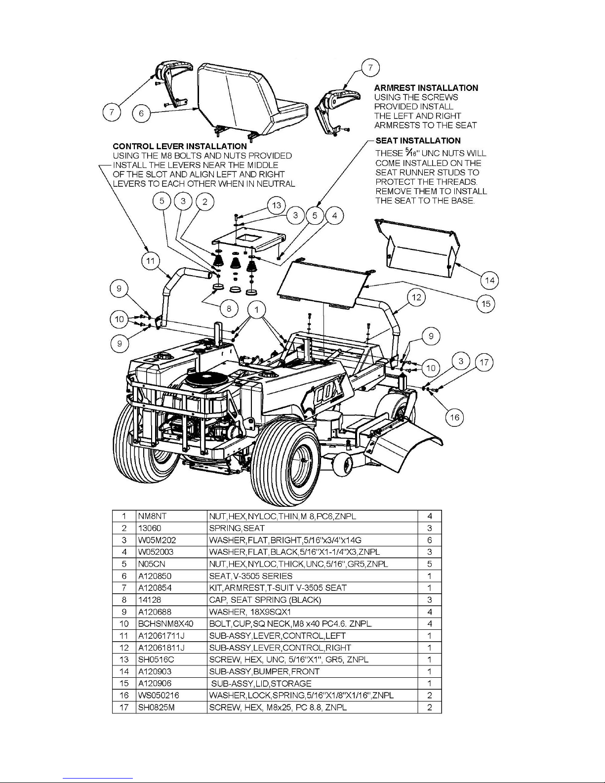
Seat Spring x 3 (13060)
Washer x 3 (W05M202)
Cup Head Bolt x 4 (M8x40)
Nyloc Nut x 4 (M8 )
Washer x 3 (W052003)
Seat Spring Cap x 3 (14128)
LH Control Lever (A12061711J)
RH Control Lever (A12061811J)
TYRE PRESSURE
Before operation ensure that all tyre pressures
are equal from side to side. The recommended
pressures are:-
Front Wheel:-140 Kpa (20psi) approximately.
Rear Wheel:- 105 Kpa (15psi) 18x8.50-8
90 Kpa (13psi) 18x9.50-8
ENGINE OIL
Before operation ensure that engine oil level is
to the full mark on the dipstick. (Read engine
owners manual for correct procedure to check &
adjust oil level).
FUEL TAP
Ensure the fuel taps at the bottom inside of the
LH & RH fuel tanks are turned to the on position
before attempting to start engine. (Use
unleaded fuel only). Turn fuel taps off after
use.
SAFETY START SWITCHES
Drive Lever Switches - 16HP HON, 22HP &
24HP B&S
With Cutter PTO switch in DISENGAGED position
and Clutch/Park Brake Lever set in the ON
position and the Drive Levers in the DRIVE
position.
Attempt to start the engine.
Engine should not start.
Drive Lever Switches—23.0 HP Honda only
While sitting on stationary machine with Engine
running and Cutter PTO Switch in DISENGAGED
position and Clutch/Park Brake Lever set in the
ON position attempt to move the Drive Levers to
the DRIVE position.
Engine should stop.
Cutter PTO Switch -
With Drive Levers in the locked out NEUTRAL
position and Cutch/Park Brake Lever set in the
ON position, and Cutter PTO Switch in the
ENGAGED position.
Attempt to start engine. Engine should not
start.
Clutch/Park Brake Lever Switch -
With Cutter PTO Switch in DISENGAGED position
and the Drive Levers are set in the locked out
NEURAL position, and the Clutch/Park Brake
Lever in the OFF position. Attempt to start the
engine.
Engine should not start.
With Cutter PTO Switch in DISENGAGED position
and the Drive Levers in the locked out NEUTRAL
position and the Clutch/Park Brake Lever set in
the ON position.
Attempt to start the Engine.
Engine should start.
SAFETY STOP SWITCHES
Seat Switch -
While sitting on stationary machine with Engine
running ENGAGE Cutter PTO Switch. Lift weight
from Seat. Engine should stop.
While sitting on stationary machine with Engine
running and Cutter PTO Switch in DISENGAGED
position, set the Clutch/Park Brake Lever in the
OFF position and then the Drive Levers in the
DRIVE position .
Lift weight from Seat.
Engine should stop.
Clutch/Park Brake Lever Switches -
While sitting on stationary machine with Engine
running and Cutter PTO Switch in DISENGAGED
position, and Drive Levers in DRIVE position,
attempt to set the Clutch/Park Brake Lever in the
ON position.
Engine should stop.
Page 5
26 July 2013 Page 5 Cruiser Model A12013G & A16013G rev1
PRE-DELIVERY INSTALLATION OF SEAT AND CONTROL LEVERS
Page 6

26 July 2013 Page 6 Cruiser Model A12013G & A16013G
OPERATING INSTRUCTIONS
IMPORTANT
The careless or improper use of a machine of this type can be
dangerous. The manufacturer or selling agent does not accept
responsibility for accident either to the operator, to the owner or
to any person directly or indirectly or to property if such accident
is caused by circumstances arising other than by the negligence
or default of COX INDUSTRIES.
RECOMMENDED FUEL
Unleaded fuel is recommended by all manufacturers of
engines fitted to Cox products (up to 10% ethanol blended
unleaded fuel is acceptable).
SAFETY SWITCHES
Before operating machine, ensure that all safety switches are
operating correctly as per Pre-delivery Instructions. Do not
operate machine with faulty, missing or damaged safety
switches.
BLADE WARNING
Do not use mowing attachment with broken, bent, or
damaged blades, or damaged or worn bolts and nuts
otherwise damage and premature wear will result from
vibration. Recommended Cutter Blade Bolt and Nut torque
is 36-40Nm. Do not over tighten.
Keep feet and hands clear of the mowing attachment
at all times while operating or attempting to start the
machine.
WARNING
DO NOT OPERATE THE MOWING ATTACHMENT
WITHOUT DISCHARGE DEFLECTOR FITTED & DOWN.
Reference to left or right hand side of machine is determined
by sitting in the operating position on the machine.
Safety footwear is recommended when operating machine.
Mount and dismount only from the centre front or non
discharge side of machine.
Ensure machine has Clutch/Park Brake Lever set in the ON
position and Drive Levers are in the locked out NEUTRAL
position and Cutter PTO Switch is in the DISENGAGED
position while attempting to start engine.
Never allow engine revs to exceed 3600 RPM.
TO OPERATE
BEFORE STARTING/SWITCHING OFF:
Read & Follow Engine Owners Manual Instructions.
Before stopping the engine:
Stop the mowing attachment
Return the engine speed control to slow position .
Then turn the Key Switch to the OFF position.
STARTING ENGINE
When starting machine, place Drive Levers in the locked out
NEUTRAL position. Ensure that Cutter PTO Switch is in the
DISENGAGED position and the Clutch/Park Brake Lever is set
in the ON position otherwise electric start will not be
activated. If engine is cold, pull choke control (if equipped)
up to choke position and engine speed control knob to fast
position, or move engine speed control knob to choke
position. Turn key switch to start position and release to the
on position once engine has started. Once engine is running
gradually return the choke control (if equipped) to depressed
position, or move engine speed control to the fast position.
Do not continue to operate the engine in the choke position.
If engine is hot move engine speed control to the fast
position. Turn key switch to start position and release to the
on position once engine has started.
TO OPERATE THE MOWING ATTACHMENT:
Bring the engine up to the normal operating speed.
The Mowing Attachment is engaged by puling up the large
yellow knob (P.T.O. Switch) on the left hand control panel.
Before starting ensure knob is in the disengaged position
(down). For safety it is advisable that the mowing
attachment be not operating (Cutter PTO Switch be in the
disengaged position) other than when mowing grass.
TO DRIVE FORWARD/REVERSE:
Engine speed and ultimate drive speed is regulated by
setting the engine speed control to desired engine speed.
To drive forward push both the drive control levers forward
from the neutral position.
To drive in reverse pull both the drive control levers back
from the neutral position.
The further the drive control levers are moved from neutral
the faster the drive speed.
To slow down when driving forward pull both drive control
levers back.
To slow down when driving in reverse push both drive
control levers forward.
The position of the drive control levers can be used to
control the ground speed, especially in heavier conditions.
Owing to the inline action of the drive levers, it is possible to
take the machine straight from forward to reverse and vice
versa.
MANOEUVRING/TURNING:
The independent forward and reverse operation of 2
separate drives makes the machine very manoeuvrable and
the sharpest turns can be negotiated easily and quickly.
Move the left hand drive control lever forward to turn the
machine in a right hand turn direction.
Move the right hand drive control lever forward to turn the
machine in a left hand turn direction
Move the left hand drive control lever backwards to turn the
machine in a left hand turn direction.
Move the right hand drive control lever backwards to turn
the machine in a right hand turn direction.
Adjustment of the speed of each rear wheel to suit the
turning manoeuvre required will minimise the possible
damage to the turf caused by having one wheel rotating too
slow for the manoeuvre required.
TO BRAKE (WITH ENGINE RUNNING):
The drive levers should be used to stop the machine travel.
Do not use the park brake lever to stop the machine travel
except in an emergency as the park brake mechanism will be
permanently damaged.
If travelling forward pull both drive control levers backwards
evenly until the machine travel stops, then return both the
drive control levers to the neutral position.
If travelling in reverse push both control levers forward
evenly until the machine travel stops, then return both the
drive control levers to the neutral position.
CLUTCH/PARK AND TRANSPORTATION BRAKE:
The clutch/park brake lever is located on the front left hand
side of the control housing. Pull the lever up fully and to the
right then lower into the “L” slot to engage the brake. Pull
the lever up and to the left out of the “L” slot and then lower
completely to disengage clutch/park brake.
Do not attempt to bring the machine to a stop using
the Clutch/Park Brake Lever as permanent damage
will be done to the Park/Brake mechanism.
CUTTING HEIGHT ADJUSTMENT:
The cutter height adjustment lever is located on the front
right hand side of the control housing, and may be raised to
suit various conditions.
To raise the mowing attachment, lift the height adjustment
lever to the desired height. It is not necessary to depress
the button when lifting the mowing attachment.
To lower the mowing attachment, lift the height adjustment
lever slightly and depress button, once button is depressed
lower the mowing attachment to the desired position and
release button.
NOTE: When mowing on slopes, keep drive levers in
forward or reverse, depending on direction of travel.
The low gearing will prevent it from picking up
excessive speed. If very steep it may be necessary to
reduce engine speed slightly.
Page 7

26 July 2013 Page 7 Cruiser Model A12013G & A16013G rev1
It is the owner’s responsibility to ensure that all periodical
checks, necessary adjustments and services are carried
out.
STOP ENGINE - Never attempt any
maintenance with the engine running, remove
spark plug lead and ensure the blades have
stopped rotating.
Before servicing, disconnect spark plug wire and ground it,
disconnect battery at negative terminal, to prevent accidental
starting.
OIL CHANGING & FILTER REPLACEMENT
(ENGINE): See Engine OWNERS MANUAL and carry out
as per Engine Manufacturers Recommendations.
SERVICING ENGINE AIR CLEANER & FOAM PRECLEANER— See engine owners manual for correct method
to check and service engine air cleaner & foam pre-cleaner.
LUBRICATION OF MACHINE:
Lubrication of machine must be carried out every 25 hours of
operation or once a month, whichever occurs first. More
frequently when operated under adverse conditions.
A few drops of oil should be placed at the following
points: Height adjustment mechanism, pivot bolt and
linkages on drive levers.
Grease should be applied using a grease gun at the
grease nipple on the top end of each of the front caster
fork shafts ensuring old grease is expelled at both the top
and bottom of the shaft.
ENGINE TO TRANSAXLES V BELT ADJUSTMENT:
Adjustment of the clutch rod adjusting nut is required
periodically to allow the V belt to be spring tensioned. With
Clutch Park Brake Lever in the OFF position Adjust the space
between the Clutch Rod adjusting nut and trunnion to be
between 3mm and 6mm.
If loss of drive is experienced because of V belt slippage, and
the adjusting nut has run out of adjustment then the V belt
has worn past its serviceable limit and should be replaced.
ENGINE TO 42” CUTTER V BELT ADJUSTMENT:
Adjustment of the V Belt Spring Tensioner Bracket is
required periodically to allow the V belt to be spring
tensioned.
With the height of the Mowing Attach set in its lowest
position check on the right hand rear of the mowing
attachment that the total length of the V belt tensioner
spring is greater than 170mm. If the length of the spring
needs to be adjusted loosen the fasteners on the
tensioner bracket and move the tensioner bracket until
the spring length is between 180mm and 190mm and retension fasteners.
If loss of cutter drive is experienced because of belt
slippage, and the tensioner bracket has run out of
adjustment the belt has worn past its serviceable limit and
should be replaced.
TO CHECK BLADES:
Stop engine. Remove spark plug lead. lift deflector and
height adjustment control to highest position and inspect
blades for wear. If sharpening or replacement of mower
blades is necessary, remove the plugs near the drive
spindle pulleys and use a 9/16” socket & suitable length
extension to remove the blades, or remove the mowing
attachment for ease of blade access and general under
mowing attachment inspection (see to remove mowing
attachment section).
TO REMOVE 42” MOWING ATTACHMENT:
Remove tension spring from the V belt tensioner bracket.
Remove cutter belt from rear PTO pulley. Remove 2 x bolts
and nyloc nuts either side on rear deck hangers.
Remove pivot pin on mowing attachment from front drag
link. Remove the bolt & nut on tensioner arm link and
remove the tensioner arm link.
CLEANING MOWING ATTACHMENT:
Ensure the mowing attachment is clear of obstructions.
Attach standard garden hose to hose adaptor on either side
of mowing attachment and turn on hose. Whilst sitting in
the operators seat engage and run mowing attachment for
two minutes, water from the hose will then circulate under
the cutter and clean it. After cleaning disengage mowing
attachment and remove hose from the adaptor.
TYRE PRESSURE:
Front Wheel:-140 Kpa (20psi) approximately.
Rear Wheel:- 105 Kpa (15psi) 8.50x8
90 Kpa (13psi) 9.50x8
Uneven pressure can give an uneven finish when mowing
and may cause damage to tyres and/or tubes.
BATTERY MAINTENANCE:
Sealed battery. When not in use, a battery discharges by
as much as 1% a day, more when the climate is warm.
To make up for this loss, a boosting charge should be
given once a month. Disconnect battery terminals to
charge, then allow to stand minimum 1/2hr before reconnecting. If a battery is not used for a period of more
than three (3) months, the terminals should be
disconnected and trickle charged at two (2) amps for two
(2) hours once every three (3) months or before use.
GENUINE SPARE PARTS:
Always use Genuine Cox Factory Made Spare Parts. Use
of non-genuine COX spares will void your warranty.
SAFETY FIRST:
The use of any mechanical appliance can cause injury if
incorrect procedures are used. Please ensure that all
family members of intended operators read this manual
thoroughly.
TORQUE SETTINGS
1/4” UNC BOLT/NUT 10Nm (84lbf in)
5/16” UNC BOLT/NUT 20Nm (180lbf in)
3/8” UNC BOLT/NUT 36Nm (27lbf ft)
7/16” UNF BOLT 68Nm (50lbf ft)
6mm BOLT/NUT 9Nm (80lbf in)
20mm NUT 100Nm (74lbf ft)
5/8” UNF NUT 100Nm (74lbf ft)
We are proud that you have purchased a Cox product and urge you to follow these instructions
to obtain the maximum life for your machine. If in doubt check with your supplier.
MAINTENANCE INSTRUCTIONS
Page 8

26 July 2013 Page 8 Cruiser Model A12013G & A16013G
9 MONTHS OR 75 HOURS which ever occurs first
Change engine oil if operating under heavy load or high ambient
temperature
Check engine air cleaner foam pre-cleaner, service if required *
Check engine rotating screen/finger guard, clean if required *
Check operation of safety switches and replace if required
Check tyre pressures, adjust if required
Check mowing attachment cutter blades, bolts, nuts, housing
and guards for wear or damage, replace if required
Check for loose fasteners, tighten if required
Check drive lever for smooth action, adjust if required
*Service more often under dusty conditions, or where air borne debris is present
DATE / / HOURS...............CUSTOMER/DEALER................................................
BEFORE STORAGE
MAINTENANCE SCHEDULE
BEFORE EACH USE
Check engine oil level, adjust if required
Check engine air cleaner foam pre-cleaner, service if required
Check engine rotating screen/finger guard, clean if required
Check operation of safety switches, service if required
Check tyre pressures, adjust if required
Check for loose fasteners, tighten if required
Check cutting attachment cutter blades, bolts, nuts, housing and
guards for wear or damage, replace if required
Change engine oil - Clean machine - Lubricate as per required
EVERY 5 HOURS
Check engine oil level, adjust if required
Check engine air cleaner foam pre-cleaner, service if req.
Check engine rotating screen/finger guard, clean if required
Check operation of safety switches, service if required
Check tyre pressures, adjust if required
Check for loose fasteners, tighten if required
Check cutting attachment cutter blades, bolts, nuts, housing and
guards for wear or damage, replace if required
DATE / / HOURS..........................DEALER................................................
1 MONTH OR 5 HOURS which ever occurs first
Change engine oil
Check engine air cleaner foam pre-cleaner , service if required
Check engine rotating screen/finger guard, clean if required
Check operation of safety switches, service if required
Check tyre pressures, adjust if required
Check mowing attachment cutter blades, bolts, nuts, housing , and
guards for damage, replace if required
Check drive levers, adjust if required
Check for loose fasteners, tighten if required
DATE / / HOURS.......................CUSTOMER................................................
3 MONTH OR 25 HOURS which ever occurs first
Change engine oil if operating under heavy load or high ambient
temperature
Check engine air cleaner foam pre-cleaner, service if required *
Check engine rotating screen/finger guard, clean if required *
Check operation of safety switches and replace if required
Check tyre pressures, adjust if required
Check mowing attachment cutter blades, bolts, nuts, housing
and guards for wear or damage, replace if required
Check for loose fasteners, tighten if required
*Service more often under dusty conditions, or where air borne debris is present
*Service more often under dusty conditions, or where air borne debris is present
DATE / / HOURS..........................DEALER................................................
Change engine oil if operating under heavy load or high ambient
temperature
Check engine air cleaner foam pre-cleaner, service if required *
Check engine rotating screen/finger guard, clean if required *
Check operation of safety switches and replace if required
Check tyre pressures, adjust if required
Check mowing attachment cutter blades, bolts, nuts, disc/s,
housing ,and guards for wear or damage, replace if required
Check for loose fasteners, tighten if required
6 MONTH OR 50 HOURS which ever occurs first
Page 9

26 July 2013 Page 9 Cruiser Model A12013G & A16013G rev1
21 MONTHS OR 175 HOURS which ever occurs first
Change engine oil if operating under heavy load or high ambient
temperature
Check engine air cleaner foam pre-cleaner, service if required *
Check engine rotating screen/finger guard, clean if required *
Check operation of safety switches and replace if required
Check tyre pressures, adjust if required
Check mowing attachment cutter blades, bolts, nuts, housing and
guards for wear or damage, replace if required
Check for loose fasteners, tighten if required
*Service more often under dusty conditions, or where air borne debris is present
DATE / / HOURS...............CUSTOMER/DEALER................................................
24 MONTHS OR 200 HOURS which ever occurs first
Replace engine oil filter
Change engine oil
Check engine spark plug, clean, adjust, or replace if required
If fitted clean engine exhaust spark arrestor
Check engine air cleaner foam pre-cleaner , service if required *
Check engine air cleaner cartridge, service if required
Clean engine cooling system*
Check operation of safety switches, service if required
Check tyre pressures, adjust if required
Check mowing attachment cutter blades, bolts, nuts, housing and
guards for wear or damage, replace if required
Check belts for wear or damage, replace if required
Check drive lever for smooth action, adjust if required
Check for loose fasteners, tighten if required
*Service more often under dusty conditions, or where air borne debris is present
DATE / / HOURS..........................DEALER................................................
12 MONTHS OR 100 HOURS which ever occurs first
DATE / / HOURS..........................DEALER................................................
*Service more often under dusty conditions, or where air borne debris is present
Change engine oil filter
Change engine oil
Check engine spark plug, clean, adjust, or replace if required
If fitted clean engine exhaust spark arrester
Check engine air cleaner foam pre-cleaner , service if required *
Check engine air cleaner cartridge, service if required*
Clean engine cooling system*
Replace in-line fuel filter
Check for loose fasteners, tighten if required
Check operation of safety switches, service if required
Check tyre pressures, adjust if required
Check mowing attachment cutter blades, bolts, nuts, housing and
guards for wear or damage, replace if required
Check drive lever for smooth action, adjust if required
Re-tension rear wheel retaining nut/s
Check belts for wear or damage, replace if required
*Service more often under dusty conditions, or where air borne debris is present
15 MONTHS OR 125 HOURS which ever occurs first
DATE / / HOURS................CUSTOMER/DEALER................................................
Change engine oil if operating under heavy load or high ambient
temperature
Check engine air cleaner foam pre-cleaner, service if required *
Check engine rotating screen/finger guard, clean if required *
Check operation of safety switches and replace if required
Check tyre pressures, adjust if required
Check mowing attachment cutter blades, bolts, nuts, housing and
guards for wear or damage, replace if required
Check for loose fasteners, tighten if required
Check belts for wear or damage, replace if required
18 MONTHS OR 150 HOURS which ever occurs first
*Service more often under dusty conditions, or where air borne debris is present
DATE / / HOURS..........................DEALER................................................
Change engine oil
If fitted clean engine exhaust spark arrestor
Check engine air cleaner foam pre-cleaner , service if required *
Check engine rotating screen/finger guard , clean if required *
Check operation of safety switches, service if required
Check tyre pressures, adjust if required
Check mowing attachment cutter blades, bolts, nuts, housing and
guards for wear or damage, replace if required
Check belts for wear or damage, replace if required
Check drive lever for smooth action, adjust if required
Check for loose fasteners, tighten if required
Page 10

26 July 2013 Page 10 Cruiser Model A12013G & A16013G
27 MONTHS OR 225 HOURS which ever occurs first
Change engine oil if operating under heavy load or high ambient
temperature
Check engine air cleaner foam pre-cleaner, service if required *
Check engine rotating screen/finger guard, clean if required *
Check operation of safety switches and replace if required
Check tyre pressures, adjust if required
Check mowing attachment cutter blades, bolts, nuts, housing and
guards for wear or damage, replace if required
Check for loose fasteners, tighten if required
*Service more often under dusty conditions, or where air borne debris is present
DATE / / HOURS................CUSTOMER/DEALER................................................
30 MONTHS OR 250 HOURS which ever occurs first
Change engine oil
If fitted clean engine exhaust spark arrestor
Check engine air cleaner foam pre-cleaner , service if required *
Check engine rotating screen/finger guard , clean if required *
Check operation of safety switches, service if required
Check tyre pressures, adjust if required
Check mowing attachment cutter blades, bolts, nuts, housing and
guards for wear or damage, replace if required
Check belts for wear or damage, replace if required
Check drive lever for smooth action, adjust if required
Check for loose fasteners, tighten if required
*Service more often under dusty conditions, or where air borne debris is present
DATE / / HOURS..........................DEALER................................................
33 MONTHS OR 275 HOURS which ever occurs first
Change engine oil if operating under heavy load or high ambient
temperature
Check engine air cleaner foam pre-cleaner, service if required *
Check engine rotating screen/finger guard, clean if required *
Check operation of safety switches and replace if required
Check tyre pressures, adjust if required
Check mowing attachment cutter blades, bolts, nuts, housing and
guards for wear or damage, replace if required
Check for loose fasteners, tighten if required
*Service more often under dusty conditions, or where air borne debris is present
DATE / / HOURS.................CUSTOMER/DEALER................................................
36 MONTHS OR 300 HOURS which ever occurs first
Replace engine oil filter
Change engine oil
Check engine spark plug, clean, adjust, or replace if required
If fitted clean engine exhaust spark arrestor
Check engine air cleaner foam pre-cleaner , service if required *
Check engine air cleaner cartridge, service if required
Clean engine cooling system*
Check operation of safety switches, service if required
Check tyre pressures, adjust if required
Check mowing attachment cutter blades, bolts, nuts, housing and
guards for wear or damage, replace if required
Check belts for wear or damage, replace if required
Check drive lever for smooth action, adjust if required
Check for loose fasteners, tighten if required
*Service more often under dusty conditions, or where air borne debris is present
DATE / / HOURS..........................DEALER................................................
Page 11
26 July 2013 Page 11 Cruiser Model A12013G & A16013G rev1
Page 12
26 July 2013 Page 12 Cruiser Model A12013G & A16013G
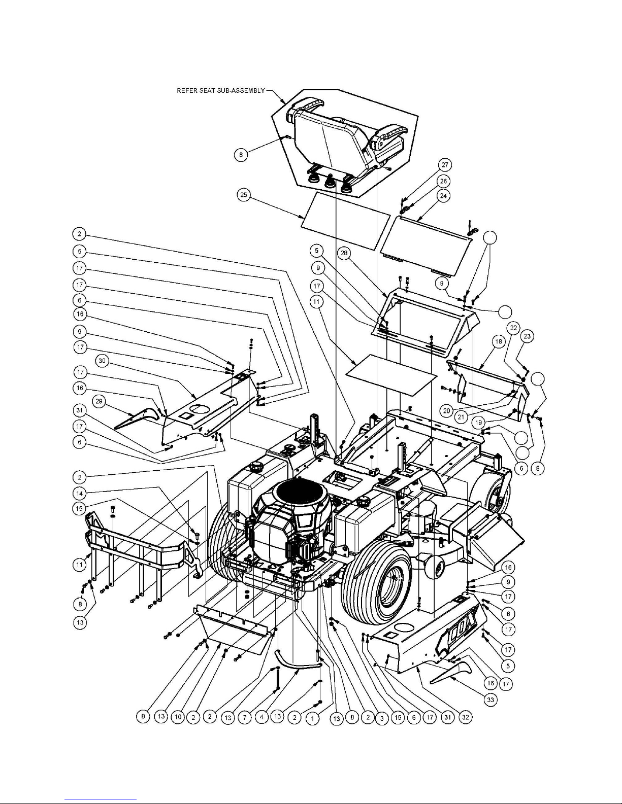
BODY OUTER COMPONENTS
34
17
35
17
13
Page 13

26 July 2013 Page 13 Cruiser Model A12013G & A16013G rev1
BODY OUTER COMPONENTS
ITEM PART NUMBER DESCRIPTION QTY
1 B0860M Bolt 1
2 NM8NT Nut 11
3 NM10NT Nut 2
4 A120578R Protector, Clutch 1
5 SH0616M Screw 2
6 NM6NT Nut 4
7 B08110M Bolt 1
8 SH0820M Screw 4
9 WS040816 Washer, Lock, Spring 4
10 A120709R Guard, Muffler 1
11 A120743R Grill, Engine, Red, Honda 1
A120741B Grill, Engine, Black, B&S 1
13 W08MN Washer 15
14 SH1025M Screw 2
15 W10MN Washer 4
16 BHSSM6X16 Screw, Button, Hex Soc 6
17 W06MN Washer 12
18 A120918R Bumper, Front 1
19 NCM8X3.2 Nut, Cage 2
20 NCM6X1.6X9.5 Nut, Cage 2
21 NM4NT Nut 2
22 14159 Button, Bonnet 2
23 SCM4X30 Screw, Csk 2
24 A120908R Lid, Storage 1
25 A120805 Non-Skid, Footrest 1
26 96114 Strap, Bonnet 2
27 PR04M4.8 Rivet 2
28 A120904R Frame, Footrest 1
29 A120912 Trim, Arch, Wheel, Left 1
30 A120925R Mudguard, Left 1
31 AM274 Fastener, Pushon 8
32 A120928R Mudguard, Right, Red 1
33 A120913 Trim, Arch, Wheel, Right 1
34 SH0620M Screw 4
35 WS050216 Washer, Lock, Spring 2
Page 14
26 July 2013 Page 14 Cruiser Model A12013G & A16013G
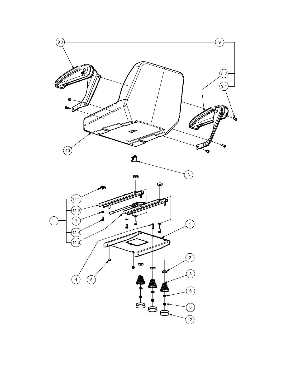
SEAT COMPONENTS
Page 15

26 July 2013 Page 15 Cruiser Model A12013G & A16013G rev1
SEAT COMPONENTS
ITEM PART NUMBER DESCRIPTION QTY
1 A120620R Mount, Seat, Red 1
2 W052003 Washer 3
3 13060 Spring, Seat 3
4 SH0516C Screw 1
5 N05CN Nut 5
6 W05M202 Washer 3
7 WS050216 Washer, Lock, Spring 4
8 SP1PNCSM Switch, Plunger 1
9 A120854 Kit, Armrest, T-Suit V-3505 Seat 1
9.1 Screw, Pan, Cross Recess, Unc, 5/16"X 3/4", Black 6
9.2 Armrest, Right 1
9.3 Armrest, Left 1
10 A120850 Seat 1
11 A120852 Kit, Adjust, Seat, 4" Travel 1
11.1 Spacer, 5/16"X1-1/4"X1/4", Plastic, Black 4
11.2 Runner, Seat 1
11.3 Adjuster, Seat, 4" Travel 1
11.4 Screw, Pan, Cross Recess, Unc, 5/16"X 3/4", Black 4
12 14128 Cap, Seat Spring 3
Page 16
26 July 2013 Page 16 Cruiser Model A12013G & A16013G
ENGINE AUXILLARY COMPONENTS 16HP HONDA
Page 17

26 July 2013 Page 17 Cruiser Model A12013G & A16013G rev1
ENGINE AUXILLARY COMPONENTS 16HP HONDA
ITEM PART NUMBER DESCRIPTION QTY
1 A120726 Valve, Oil, Shut Off, 15558-772-010 1
2 80037 Grommet 6
3 90167 Muffler, Exhaust 1
4 90168 Clamp, Hose, T-Bolt 4
5 A119121C Pipe, Exhaust, Hon, 530cc, L/Boss, Left 1
6 A119123C Pipe, Exhaust, Hon, 530cc, L/Boss, Right 1
7 A120943 Pulley, Engine 1
8 A120516 Clutch/Brake, Elecmagnet 1
9 A120531 Fuel Line, 50l 1
10 A120595Z Tang, Clutch 1
11 A120630 Fuel Line, 200l 1
12 A120631 Fitting, Tee, Barb, 3/16", Brass 1
13 A120660 Tank, Fuel, 11 L, Right 1
14 AM293 Petrol Tap 2
15 CF01 Cap, Fuel 2
16 A120661 Tank, Fuel, 11 L, Left 1
17 AM294 Grommet 2
18 A120713Z Bracket, Support, Muffler 1
19 A120715 Mount, Exhaust 2
20 A120717Z Bracket, Mount, Exhaust 1
21 A120721 Spacer, Recoil R280, Red, Hon, 28405z0a000zc 1
22 A120722 Bracket, Recoil Mount, Hon, 28406z0a000 1
23 A120723 Protector, Comp, R280, Red, Hon19620ze3l60zd 1
24 A120724 Bolt, Flange, 6x 8, Hon, 957010600807 3
25 A120725 Nut, Flange, 6mm, Hon, 9405006070 3
26 A120755 Control, Speed, Engine, 16.0h, L=940 1
27 A120871 Line, Fuel5, L= 400 1
28 A126266 Handle, Control, Speed 1
29 AM175 Key 1
30 AM183 Spring, Extension 1
31 B0408TFS Screw 4
32 B0756F Bolt 1
33 BHSSM5X12 Screw, Button, Hex Soc 2
34 Engine, 16.0hp, V2cyl, Elec, Hon, Gxv530 1
35 NHCM6 Nut 10
36 NHM6 Nut 4
37 NM5NT Nut 2
38 NM6NT Nut 6
39 NM8NT Nut 2
40 SH0620M Screw 2
41 SH0820M Screw 2
42 STF0618 Screw 4
43 W041216 Washer 6
44 W06MN Washer 8
45 W06S Washer, Lock 4
46 W071416 Washer 2
47 WS071008 Washer, Lock, Spring 1
48 A120944Z Spacer, Sleeve 1
Page 18

26 July 2013 Page 18 Cruiser Model A12013G & A16013G
ENGINE AUXILLARY COMPONENTS 22HP & 24HP B&S 42” Cut Only
Page 19

26 July 2013 Page 19 Cruiser Model A12013G & A16013G rev1
ENGINE AUXILLARY COMPONENTS 22HP & 24HP B&S 42” Cut Only
ITEM PART NUMBER DESCRIPTION QTY
1 A120660 Tank, Fuel, 11 L, Right 1
2 AM293 Petrol Tap 2
3 AM294 Grommet 2
4 CF01 Cap, Fuel 2
5 A120661 Tank, Fuel, 11 L, Left 1
6 80037 Grommet 6
7 A120514 Pulley, Engine 1
8 AM175 Key 1
9 W06S Washer, Lock, Int Tooth 4
10 STF0618 Screw 4
11 A120516 Clutch/Brake, Elecmagnet 1
12 A120595Z Tang, Clutch 1
13 SH0820M Screw 2
14 NM8NT Nut 2
15 AM183 Spring, Extension 1
16 A120770 Control, Speed, Engine 1
17 A126266 Handle, Control, Speed 1
18 W071416 Washer 2
19 WS071008 Washer, Lock, Spring 1
20 B0748F Bolt 1
21 A120531 Fuel Line, 50l 1
22 A120631 Fitting, Tee, Barb 1
23 A120871 Line, Fuel, 5,L= 400 1
24 A120630 Fuel Line, 200l 1
25 BHSSM5X12 Screw, Button, Hex Soc 2
26 NM5NT Nut 2
27 13206 Valve, Drain, Oil 1
28 E24.0I2VEB Engine, 24.0hp, V2cyl, Elec, B&S, Blk, 44567 1
29 A120831 Muffler, Exhaust, Engine, B&S, 22.0hp 1
30 A120727C Pipe, Exhaust, B&S 2
31 GASKET B&S 4
32 A120748Z Link, Mount, Muffler 1
33 SH0825M Screw 4
34 NHCM8 Nut 4
35 Exhaust Flange Bolt 4
36 WS050216 Washer, Lock, Spring 4
37 B0408TFS Screw 1
38 SH0616M Screw 1
39 W041216 Washer 2
40 NHCM6 Nut 1
41 A120734 Inadvert Cover 1
Page 20

26 July 2013 Page 20 Cruiser Model A12013G & A16013G
ENGINE AUXILLARY COMPONENTS 24HP B&S 48” Cut Only
Page 21

26 July 2013 Page 21 Cruiser Model A12013G & A16013G rev1
ENGINE AUXILLARY COMPONENTS 24HP B&S 48” Cut Only
ITEM PART NUMBER DESCRIPTION QTY
1 80037 Grommet 6
2 A120514 Pulley, Engine 1
3 A120660 Tank, Fuel, 11 L, Right 1
4 AM293 Petrol Tap 2
5 AM294 Grommet 2
6 CF01 Cap, Fuel 2
7 AM175 Key 1
8 A120661 Tank, Fuel, 11 L, Left 1
9 W06S Washer, Lock 4
10 STF0618 Screw 4
11 A120895Z Tang, Clutch 1
12 SH0820M Screw 2
13 NM8NT Nut 2
14 AM183 Spring, Extension 1
15 A120770 Control, Speed, Engine, L= 520, No Knob 1
16 A126266 Handle, Control, Speed 1
17 W071416 Washer 2
18 WS071008 Washer, Lock, Spring 1
19 B0748F Bolt 1
20 A120531 Fuel Line, 50l 1
21 A120631 Fitting, Tee, Barb, 3/16", Brass 1
22 A120871 Line, Fuel,5, L= 400 1
23 A120630 Fuel Line, 200l 1
24 BHSSM5X12 Screw, Button, Hex Soc 2
25 NM5NT Nut 2
26 13206 Valve, Drain, Oil 1
27 Engine, 24.0hp, V2cyl, Elec, B&S, Blk, 44567 1
28 A120831 Muffler, Exhaust, Engine 1
29 A120727C Pipe, Exhaust 2
30 Gasket B&S 4
31 A120748Z Link, Mount, Muffler 1
32 SH0825M Screw 4
33 NHCM8 Nut, Hex, Conelok 4
34 Exhaust Flange Bolt 4
35 WS050216 Washer, Lock, Spring 4
36 B0408TFS Screw 1
37 SH0616M Screw 1
38 W041216 Washer 2
39 NHCM6 Nut, Hex, Conelok 1
40 A120734 Inadvert Cover, B&S, 797420 1
41 A160003Z Spacer, Clutch/Brake 1
42 88074 Clutch/Brake, Electromagnetic 1
Page 22

26 July 2013 Page 22 Cruiser Model A12013G & A16013G
ENGINE AUXILLIARY COMPONENTS 23HP HONDA 42” Cut Only
Page 23

26 July 2013 Page 23 Cruiser Model A12013G & A16013G rev1
ENGINE AUXILLIARY COMPONENTS 23HP HONDA 42” Cut Only
ITEM PART NUMBER DESCRIPTION QTY
1 Engine, 23.0hp, V2cyl, Elec, Hon, GXV630 1
2 80037 Grommet 4
3 A126266 Handle, Control, Speed 1
4 A120755 Control, Speed, Engine, L=940 1
5 A120856 Control, Choke 1
6 N06FT Nut 1
7 W06S Washer, Lock 1
8 A120660 Tank, Fuel, 11 L, Right 1
9 AM293 Petrol Tap 2
10 AM294 Grommet 2
11 CF01 Cap, Fuel 2
12 A120661 Tank, Fuel, 11 L, Left 1
13 BHSSM5X12 Screw, Button, Hex Soc 1
14 NM5NT Nut 1
15 A120726 Valve, Oil, Shut Off, 15558-772-010 1
16 A120843C Pipe, Exhaust 2
17 A120629 Fuel Line, 360l 1
18 A120631 Fitting, Tee, Barb, 3/16", Brass 1
19 A120871 Line, Fuel, 5,L= 400 1
20 A120630 Fuel Line, 200l 1
21 A120944Z Spacer, Sleeve 1
22 A120943 Pulley, Engine 1
23 W10MN Washer 8
24 B1040M Bolt 4
25 NHCM10 Nut, Hex, Conelok 4
26 AM175 Key 1
27 A120516 Clutch/Brake, Elecmagnet 1
28 W071416 Washer 2
29 WS071006 Washer, Lock, Spring 1
30 B0756F Bolt 1
31 A120595Z Tang, Clutch 1
32 SH0820M Screw 2
33 NM8NT Nut 2
34 AM183 Spring, Extension 1
35 A120842 Gasket, Exhaust, Hon, 18333-Ze3-801 4
36 A120841 Muffler, Exhaust, Honda 1
37 SH0825M Screw 4
38 NFM8 Nut, Hex, Flange 4
Page 24

26 July 2013 Page 24 Cruiser Model A12013G & A16013G
ENGINE AUXILLARY COMPONENTS 23HP HON 48” Cut Only
Page 25

26 July 2013 Page 25 Cruiser Model A12013G & A16013G rev1
ENGINE AUXILLARY COMPONENTS 23HP HON 48” Cut Only
ITEM PART NUMBER DESCRIPTION QTY
1 Engine, 23.0hp, V2cyl, Elec, Hon, GXV630 1
2 80037 Grommet 4
3 A126266 Handle, Control, Speed, Black 1
4 A120755 Control, Speed, Engine, L=940 1
5 A120856 Control, Choke 1
6 N06FT Nut 1
7 W06S Washer, Lock 1
8 A120660 Tank, Fuel, 11 L, Right 1
9 AM293 Petrol Tap 2
10 AM294 Grommet 2
11 CF01 Cap, Fuel 2
12 A120661 Tank, Fuel, 11 L, Left 1
13 BHSSM5X12 Screw, Button, Hex Soc 1
14 NM5NT Nut 1
15 A120726 Valve, Oil, Shut Off, 15558-772-010 1
16 A120843C Pipe, Exhaust 2
17 A120629 Fuel Line, 360l 1
18 A120631 Fitting,Tee,Barb,3/16",Brass 1
19 A120871 Line,Fuel, 5,L= 400 1
20 A120630 Fuel Line, 200l 1
21 A120944Z Spacer, Sleeve 1
22 A120943 Pulley, Engine 1
23 W10MN Washer 8
24 B1040M Bolt 4
25 NHCM10 Nut, Hex, Conelok 4
26 AM175 Key 1
28 W071416 Washer 2
29 WS071006 Washer, Lock, Spring 1
30 SH0820M Screw 2
31 NM8NT Nut 2
32 AM183 Spring, Extension, Park Brake 1
33 A120842 Gasket, Exhaust, Hon, 18333-Ze3-801 4
34 A120841 Muffler, Exhaust, Honda 1
35 SH0825M Screw 4
36 NFM8 Nut, Hex, Flange 4
37 A160003Z Spacer, Clutch/Brake 1
38 A120895Z Tang, Clutch, Znpl 1
39 88074 Clutch/Brake, Electromagnetic 1
40 B0748F Bolt 1
Page 26

26 July 2013 Page 26 Cruiser Model A12013G & A16013G
Page 27

26 July 2013 Page 27 Cruiser Model A12013G & A16013G rev1
ELECTRICAL COMPONENTS 16HP HONDA
ITEM PART NUMBER DESCRIPTION QTY
1 Battery (purchase locally) 1
2 Engine 1
3 KIT250 Kit, Switch, Key, 3 Posn, Magneto, Inc Bezel 1
4 AM211 Hour Meter 1
5 A102136 Switch, PTO 1
6 Regulator/Rectifier, Honda 1
7 SP1PNCSM Switch, Plunger 1
8 A120516 Clutch/Brake, Elecmagnet 1
9 SKIT133 Switch, Plunger Incl Cover 3
10 Fuse, Blade, 15AMP Blue 1
11 A143113 Harness, Wiring, Engine, Honda 1
12 15235 Lead, Battery, Black 1
13 84132 Lead, Battery, Red 1
14 A120705 Harness, Wiring, Main 1
A102190 Ring, Retainer, Switch, Pto 1
14130 Cover, Battery, Terminal 2
CSP2SM Cover, Switch, Plunger 2
AM015 Key, Switch 1
SH0616M Screw 4
A120707Z12H Bracket, Mounting, Regulator/Rectifier 1
N04C Nut 2
NM6NT Nut 2
W040818 Washer 2
A120567R Restraint, Battery, Red 1
WS040816 Spring Washer 4
W06MN Washer 4
A120569 Spill Mat 1
B0625M Bolt 2
Page 28

26 July 2013 Page 28 Cruiser Model A12013G & A16013G
Page 29

26 July 2013 Page 29 Cruiser Model A12013G & A16013G rev1
ELECTRICAL COMPONENTS 22HP & 24HP B & S
ITEM PART NUMBER DESCRIPTION QTY
1 Battery (purchase locally) 1
2 Engine 1
3 KIT250 Kit, Switch, Key, 3 Posn, Magneto, Inc Bezel 1
4 AM211 Hour Meter 1
5 A102136 Switch, PTO 1
6 KIT249 Solenoid 1
7 SP1PNCSM Switch, Plunger 1
8 A120516 Clutch/Brake, Elecmagnet 1
9 SKIT133 Switch, Plunger Incl Cover 3
10 Fuse, Blade, 20AMP Yellow 1
11 15235 Lead, Battery, Black 1
12 A120527 Lead, Battery, Red, L=150 1
13 84132 Lead, Battery, Red, L=295 1
14 A120705 Harness, Wiring, Main 1
A102190 Ring, Retainer, Switch, Pto 1
14130 Cover, Battery, Terminal 2
CSP2SM Cover, Switch, Plunger 2
AM015 Key, Switch 1
SH0616M Screw 6
A120563Z12J Bracket, Mounting, Solenoid 1
N04C Nut 2
NM6NT Nut 2
W040818 Washer 2
A120567R Restraint, Battery, Red 1
WS040816 Spring Washer 4
W06MN Washer 4
A120569 Spill Mat 1
Page 30

26 July 2013 Page 30 Cruiser Model A12013G & A16013G
Page 31

26 July 2013 Page 31 Cruiser Model A12013G & A16013G rev1
ELECTRICAL COMPONENTS 23HP HONDA
ITEM PART NUMBER DESCRIPTION QTY
1 Battery, Supercharge, Mfu1, 340cca 1
2 Engine, 23.0hp, V2cyl, Elec, Hon, Gxv630 1
3 A120839 Switch, Key 1
4 AM211 Hour Meter 1
5 A102136 Switch, Pto, Push-Pull, Nodtdt, Yellow, Horiz 1
6 Regulator/Rectifier, Honda 1
7 SP1PNCSM Switch, Plunger, 1 Pole, Nc, Snap Mtg 1
8 A120516 Clutch/Brake, Elecmagnet 1
9 SKIT133 Switch, Plunger Incl Cover 3
10 Fuse, Blade, 20 Amp, Yellow 1
11 A120857 Harness, Wiring, Engine, Hon, 23.0 1
12 15235 Lead, Battery, Black 1
13 89092 Lead, Battery, Red, L=295 1
14 A120705 Harness, Wiring, Main, Cruiser 1
16 SKIT132 Switch, Plunger Incl Cover 1
17 Relay, Change Over, 12v, 30a 1
CSP2PSM Cover, Switch, Plunger 3
CSPIPSM Cover, Switch, Plunger 1
A120190 Ring, Retainer, Switch, Pto 1
14130 Cover, Terminal, Batter, Red 1
A120863 Hardware, Pair, Key, Miled+Nut+Lockwasher 1
SH0616M Screw 6
A120707Z12H Bracket, Mounting, Regulator/Rectifier 1
N04C Nut 2
NMCNT Nut 2
W06MN Washer, Flat 4
NHM6 Nut 2
WS040816 Washer, Lock, Spring 4
A120569 Spill, Mat 1
B0625M Bolt 2
Page 32

26 July 2013 Page 32 Cruiser Model A12013G & A16013G
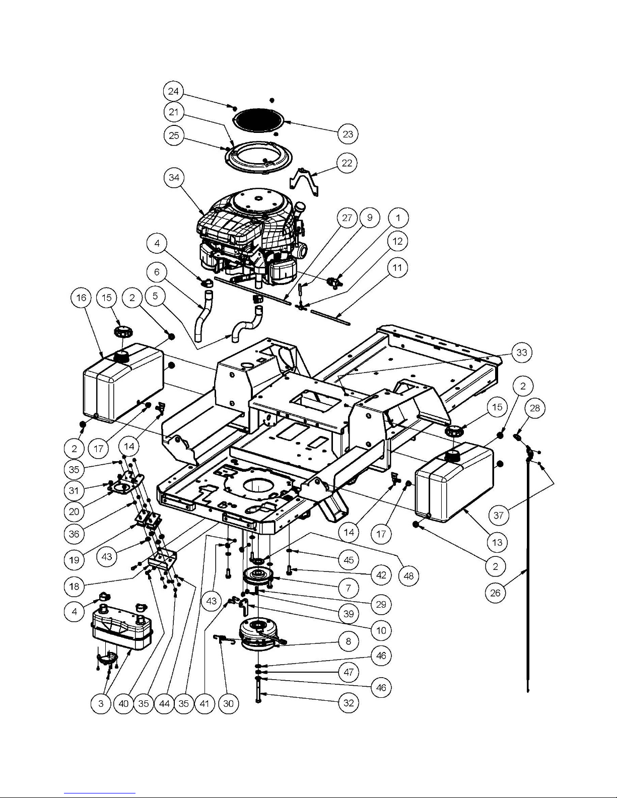
CONSOLE COMPONENTS 16HP HONDA, 22HP,24HP B&S
36
Page 33

26 July 2013 Page 33 Cruiser Model A12013G & A16013G rev1
CONSOLE COMPONENTS 16HP HONDA, 22HP,24HP B&S
ITEM PART NUMBER DESCRIPTION QTY
1 SH0616M Screw 26
2 NM6NT Nut 26
3 WS040816 Washer, Lock, Spring 23
4 A120920B Mount, Tank, Fuel, Left 1
5 A120922B Mount, Tank, Fuel, Right 1
6 W06MN Washer 41
7 A120878 Console, Right 1
8 KIT250 Kit, Switch, Key, 3 Posn, Magneto, Inc Bezel 1
8.1 Body, Switch, Key, Magneto, 3 Posn, 6 Term, 5/8"Unf 1
8.2 W10S Washer, Lock, Int Tooth, 5/8" 1
8.3 Nut, Hex, Pressed, Unf, 5/8" 1
8.4 A120872Z Washer, D 1
8.5 A120870 Bezel, Switch, Key, 5/8" 1
9 NCM6X1.6X9.5 Nut, Cage 2
10 NM8NT Nut 1
11 SH1030M Screw 1
12 NM5NT Nut 2
13 BHSSM5X12 Screw, Button, Hex Soc 2
14 SP2PNONCSM Switch, Plunger 1
15 80037 Grommet 2
16 CSP2PSM Cover, Switch, Plunger 1
17 A126266 Handle, Control, Speed 1
18 A120770 Control, Speed, Engine, No Knob 1
19 A120877 Console, Left 1
20 80037 Grommet 2
21 A102136 Switch, PTO, Push-Pull 1
22 A102190 Ring, Retainer, Switch, PTO 1
23 AM211 Hour Meter 1
24 SP2PNONCSM Switch, Plunger 1
25 CSP2PSM Cover, Switch, Plunger 1
26 NM8NT Nut 1
27 NCM6X1.6X9.5 Nut, Cage 2
28 SH0830M Screw 1
29 BHSSM5X12 Screw, Button, Hex Soc 1
30 NM5NT Nut 1
31 W05MN Washer 2
32 A120937R Console, Left 1
33 A120911 Holder, Drink 1
34 NCM6X1.6X9.5 Nut, Cage 4
35 W041018 Washer 4
36 BHSSM6X16 Screw, Button, Hex Soc 4
Page 34

26 July 2013 Page 34 Cruiser Model A12013G & A16013G
CONSOLE COMPONENTS 23HP HONDA
Page 35

26 July 2013 Page 35 Cruiser Model A12013G & A16013G rev1
CONSOLE COMPONENTS 23HP HONDA
ITEM PART NUMBER DESCRIPTION QTY
1 80037 Grommet 6
2 A102136 Switch, Pto 1
3 A102190 Ring, Retainer, Switch, Pto 1
4 AM211 Hour Meter 1
5 NM8NT Nut 2
6 SH0830M Screw 2
7 A120941R Console, Left, Hon 1
8 A120839 Switch, Key 1
9 Body, Switch, Key 1
10 Washer, Lock 1
11 Nut 2
12 WM20S Washer, Lock 1
13 A120848R Console, Right 1
14 NM5NT Nut 2
15 BHSSM5X12 Screw, Button, Hex Soc 2
16 A126266 Handle, Control, Speed 1
17 A120856 Control, Choke 1
18 N06FT Nut 1
19 W06S Washer, Lock 1
20 A120920B Mount, Tank, Fuel, Left 1
21 A120922B Mount, Tank, Fuel, Right 1
22 SH0616M Screw 18
23 NM6NT Nut 10
24 W06MN Washer 28
25 WS040816 Washer, Lock 8
Page 36

26 July 2013 Page 36 Cruiser Model A12013G & A16013G
DRIVE CONTROL COMPONENTS
Page 37

26 July 2013 Page 37 Cruiser Model A12013G & A16013G rev1
DRIVE CONTROL COMPONENTS
ITEM PART NUMBER DESCRIPTION QTY
1 NM8NT Nut 4
2 N06CN Nut 4
3 B0620C Bolt 4
4 A120688 Washer 4
5 AM020 End, Rod, Stamp 2
6 N06F Nut 2
7 RE38LHINT End, Rod, Stamp 2
8 N06FLH Nut 2
9 A120900Z Rod, Link 2
10 A120522 Plug 2
11 A120586R11J Lever, Control, Left 1
12 A120686 Grip, Hand 2
13 BCHSNM8X40 Bolt, Cup, Sq Neck 4
14 A120584R11J Lever, Control, Right 1
15 NM8NT Nut 9
16 W102015 Washer 4
17 C05 Circlip, Ext, "E"Type 4
18 W05M202 Washer 4
19 WS050216 Washer, Lock, Spring 2
20 SH0825M Screw 2
21 B0840M Bolt 2
22 B0830M Bolt 2
23 RP01 Pin, 'R' 2
24 NHM8 Nut 4
25 A120127 Damper 2
26 A120560Z Shaft, Lever, Control 2
27 A120663Z Bush, Pivot, Lever, Control 2
28 WW0816 Wave Washer 2
29 W08MN Washer 2
30 B0835M Bolt 2
31 A120773Z13G Lever, Control, Right 1
32 A120771Z13G Lever, Control, Left 1
33 A120775Z13G Link, Lever, Control 2
Page 38

26 July 2013 Page 38 Cruiser Model A12013G & A16013G
DRIVE COMPONENTS (42” ONLY)
16
Page 39

26 July 2013 Page 39 Cruiser Model A12013G & A16013G rev1
DRIVE COMPONENTS (42” ONLY)
ITEM PART NUMBER DESCRIPTION QTY
1 ZC-DPBB-4D7C-1WPX Transaxle, Hydro, HYG, (http://www.hydro-gear.com) 1
2 ZC-APBB-4D7B-1WPX Transaxle, Hydro, HYG, (http://www.hydro-gear.com) 1
3 B0860M Bolt 5
4 W051216 Washer 8
5 NM8NT Nut 11
6 W102003M Washer 6
7 NM10NT Nut 6
8 B1050M Bolt 2
9 A120578R Protector, Clutch 1
10 B1060M Bolt 4
11 V57 Belt, V 1
12 B0870M Bolt 4
13 PIFBB02 Idler, Flat 2
14 14025 Boss, Idler 2
15 W051218 Washer 3
16 14070 Sleeve, Pivot, Drive Belt Tensioning Arm 1
18 B0845M Bolt 2
19 A120625Z Arm, Tensioner, Belt, Hydro 1
20 PIFBB02 Idler, Flat 1
21 14025 Boss, Idler 1
22 A102125Z Boss, Idler 1
23 A120685 Bush, Pivot, Tensioner 2
24 A120683Z Guide, Belt 1
25 WS050216 Washer, Lock, Spring 1
26 B0835M Bolt 1
27 B08110M Bolt 1
28 15176 Boss, Idler 1
29 B0845M Bolt 1
30 A120212 Wheel 16HP, 21HP & 22HP 2
31 A120534S Rim 16HP, 21HP & 22HP 1
32 TT18X850-8SS Tyre, Tubeless 16HP, 21HP & 22HP 1
33 VSS Valve 1
34 STU18X850-8-SS Tube (Optional) 4
35 NHWF08 Nut, Hex, Wheel 8
36 AM040 Spring Extension 1
37 A120576R12J Brace, Transmission 1
38 W05M202 Washer 1
39 RP04 Pin, 'R' 1
40 A120865 Wheel 23HP & 24HP 2
41 A120897S Rim 23HP & 24HP 1
42 TT18X950-8SS Tyre, Tubeless 23HP & 24HP 1
43 VSS Valve, Tubeless 1
Page 40

26 July 2013 Page 40 Cruiser Model A12013G & A16013G
DRIVE COMPONENTS (48” ONLY)
Page 41

26 July 2013 Page 41 Cruiser Model A12013G & A16013G rev1
DRIVE COMPONENTS (48” ONLY)
ITEM PART NUMBER DESCRIPTION QTY
1 Transaxle, Hydro, Hyg, ZC-DPBB-4D7C-1WPX 1
2 Transaxle, Hydro, Hyg, ZC-APBB-4D7B-1WPX 1
3 B0860M Bolt 4
4 W051216 Washer 8
5 NM8NT Nut 12
6 W102003M Washer 6
7 NM10NT Nut 7
8 B1050M Bolt 2
9 A120578R Protector, Clutch 1
10 B1060M Bolt 4
11 V63 Belt, V 1
12 B0870M Bolt 4
13 PIFBB02 Idler, Flat 2
14 14025 Boss, Idler 2
15 W051218 Washer 3
16 14070 Sleeve, Pivot, Drive Belt Tensioning Arm 2
17 A120685 Bush, Pivot, Tensioner 4
18 A120683Z Guide, Belt 1
19 WS050216 Washer, Lock, Spring 1
20 B0835M Bolt 1
21 BB102206N Bearing, Ball 1
22 RE14INT End, Rod, Stamp 1
23 N04CN Nut 1
24 N04F Nut 1
25 A160034Z Arm, Tensioner 1
26 A160032Z Spacer, Locate, Bearing 2
27 A160080Z Rod, Link, Disengage, Drive 1
28 B0428C Bolt 1
29 A160036Z Sleeve, Clamp, End, Rod 1
30 BHSSM10X30 Screw, Button, Hex Soc 1
31 W05M202 Washer 1
32 B08110M Bolt 2
33 15176 Boss, Idler 2
34 B0845M Bolt 1
35 STU18X850-8SS Tube (Optional) 3
36 NHWF08 Nut, Hex, Wheel 8
37 AM264 Spring, Extension 2
38 A120576R12J Brace, Transmission 1
39 W05M202 Washer 1
40 RP04 Pin, 'R' 1
41 A120865 Wheel 2
42 A120897S Rim 1
43 TT18X950-8SS Tyre, Tubeless 1
44 VSS Valve, Tubeless 1
45 B0850M Bolt 1
46 A160028Z Arm, Idler 1
47 A160082Z Selector, Bypass 2
48 W041018 Washer 2
49 RP01 Pin, 'R' 2
50 W05M202 Washer 1
Page 42

26 July 2013 Page 42 Cruiser Model A12013G & A16013G
FRONT AXLE COMPONENTS
Page 43

26 July 2013 Page 43 Cruiser Model A12013G & A16013G rev1
FRONT AXLE COMPONENTS
ITEM PART NUMBER DESCRIPTION QTY
1 NM8NT Nut 2
2 NM10NT Nut 4
3 B1060M Bolt 4
4 A120593Z Pin, Front Axle Pivot 1
5 B0860M Bolt 2
6 W20MN Washer, Flat 4
7 W103506 Washer, Flat 2
8 WSM10X3.7X2.5 Washer, Lock, Spring 2
9 SH1025M Screw 2
10 A120588Z Fork, Caster 2
11 VSS Valve, Tubeless 2
12 A120520 Sleeve, Spacer, Bearing 2
13 A120590 Rim,Wheel 2
14 TT11x400-5SS Tyre, Tubeless 2
15 BB204714NN Bearing, Ball 4
16 A120609Z Axle, Wheel 2
17 AM336 Washer, Sealing, Shaft 2
18 C02 Circlip 2
19 GNTF3 Nipple, Grease 2
20 A120605Z Spacer, Front Axle Cheek Plate 4
21 A120523R Beam, Axle, Caster 1
90130 Buffer, Rubber 4
22 W10M Washer 4
23 STU350x5 Tube (Optional) 1
Page 44

26 July 2013 Page 44 Cruiser Model A12013G & A16013G
CUTTER SUSPENSION & PARK BRAKE COMPONENTS (42” ONLY)
Page 45

26 July 2013 Page 45 Cruiser Model A12013G & A16013G rev1
CUTTER SUSPENSION & PARK BRAKE COMPONENTS (42” ONLY)
ITEM PART NUMBER DESCRIPTION QTY
1 W051216 Washer 6
2 NM8NT Nut 11
3 NCM6X1.6X9.5 Nut, Cage 12
4 NM6NT Nut 9
5 B1035M Bolt 2
6 NM10NT Nut 2
7 W10MN Washer 2
8 B0645M Bolt 4
9 A120807R13C Housing, Linkage 1
10 A120561Z Pin, Pivot 1
11 A120506Z Lever, Actuating, Brake, Park 1
12 A120541R12C Lever, Adjusting, Height 1
13 A120543Z Ratchet, Adjusting, Height 1
14 13012 Bush 5
15 A120545Z Arm, Suspension, Right, Cutter 1
16 A120547Z Arm, Suspension, Left, Cutter 1
17 A120549R Bracket, Pivot, Mount, Seat 1
18 A120565Z Bush, Pivot, Link, Suspension, Cutter 2
19 A120557R Bracket, Switch, Park Brake 1
20 AM009 Hand Grip 1
21 A120655Z Rod, Push, Disengaging 1
22 AM011 Ht Adj Pawl 1
23 B0860M Bolt 1
24 A120643Z Spacer, Pawl, Adjustment, Height 1
25 AM012 Height Adjustment Pawl Push Rod Spring 1
26 AM013Q2 Height Adjustment Pawl Push Rod Button 1
27 A120659 Washer 1
28 W040818 Washer 5
29 SH0616M Screw 3
30 W122414 Washer 2
31 SH0820M Screw 2
32 W051218 Washer 4
33 A120681Z Washer, Stop 1
34 A120619Z Bush, Pivot, Suspension, Deck 2
35 B0835M Bolt 2
36 A120622R12L Link, Drag, Attachment, Mowing 1
37 AM230 Bush 4
38 SH0816M Screw 4
39 A120642 Spring,Extension 2
40 A120601Z Plate, Levelling, Cutter 1
41 13016 Pin 2
42 SH0620M Screw 5
43 A120628Z Trunnion, Clutch 1
44 C03 Circlip, Ext, "E"Type 1
45 RP01 Pin, 'R' 1
46 SH0825M Bolt 2
47 W05M202 Washer 1
Page 46

26 July 2013 Page 46 Cruiser Model A12013G & A16013G
CUTTER SUSPENSION & PARK BRAKE COMPONENTS (48” ONLY)
Page 47

26 July 2013 Page 47 Cruiser Model A12013G & A16013G rev1
CUTTER SUSPENSION & PARK BRAKE COMPONENTS (48” ONLY)
ITEM PART NUMBER DESCRIPTION QTY
1 W051216 Washer 6
2 NM8NT Nut 5
3 NCM6X1.6X9.5 Nut, Cage 12
4 NM6NT Nut 9
5 B1035M Bolt 2
6 NM10NT Nut 2
7 W10MN Washer 2
8 B0645M Bolt 4
9 A120807R13C Housing, Linkage 1
10 A120561Z Pin, Pivot 1
11 A160007Z Lever, Actuating, Brake, Park 1
12 A120541R12C Lever, Adjusting, Height 1
13 A120543Z Ratchet, Adjusting, Height 1
14 13012 Bush 5
15 A120545Z Arm, Suspension, Right, Cutter 1
16 A120547Z Arm, Suspension, Left, Cutter 1
17 A120549R Bracket, Pivot, Mount, Seat 1
18 A120565Z Bush, Pivot, Link, Suspension, Cutter 2
19 A120557Z12H Bracket, Switch, Park Brake 1
20 AM009 Hand Grip P 1
21 A120655Z Rod, Push, Disengaging 1
22 AM011 Ht Adj Pawl 1
23 B0860M Bolt 1
24 A120643Z Spacer, Pawl, Adjustment, Height 1
25 AM012 Height Adjustment Pawl Push Rod Spring 1
26 AM013Q2 Height Adjustment Pawl Push Rod Button 1
27 A120659 Washer 1
28 W040818 Washer 5
29 SH0616M Screw 3
30 W122414 Washer 2
31 SH0820M Screw 4
32 W051218 Washer 2
33 A120681Z Washer, Stop 1
34 A120619Z Bush, Pivot, Suspension, Deck 2
35 B0835M Bolt 2
36 A120622R12L Link, Drag, Attachment, Mowing 1
37 AM230 Bush 4
38 SH0816M Screw 4
39 A120642 Spring, Extension 2
40 A120601Z Plate, Levelling, Cutter 1
41 13016 Pin 2
42 SH0620M Screw 5
43 A120628Z Trunnion, Clutch 1
44 C03 Circlip, Ext, "E"Type 1
45 SH0825M Bolt 2
46 A156027Z Link, Tilt, Idler 1
47 W05M202 Washer 1
48 RP01 Pin, 'R' 1
Page 48

26 July 2013 Page 48 Cruiser Model A12013G & A16013G
CUTTER DECK COMPONENTS (42” ONLY)
Page 49

26 July 2013 Page 49 Cruiser Model A12013G & A16013G rev1
CUTTER DECK COMPONENTS (42” ONLY)
ITEM PART NUMBER DESCRIPTION QTY
1 13247 Washer 2
2 A100003 Spring, Torsion, Deflector 1
3 A100025 Key 2
4 A120597Z Plate, Link, Suspension, Cutter 2
5 A120599Z Spacer, Clamp, Mounting, Cutter 2
6 A120638Z Link, Suspension, Cutter 2
7 A100015B Housing, Bearing 2
8 BB205215NS Bearing, Ball 2
9 14085 Disc, Cutter 2
10 A100021Z Washer 2
11 A113049 Spindle, Flanged, Cutter 2
12 BB255215NN Bearing, Ball 2
13 SH0616C Screw 8
14 A121501R12H Deck, Cutter 1
15 A121503 Wheel 4
16 A121504Z Sleeve, Roller, Deck, Cutter 4
17 A121506 Pulley, Cutter 2
18 A121507R Cover, Left 1
19 A121510R Cover, Right 1
20 A121512 Grommet 2
21 A121513 Adaptor, Spray, Water 2
22 A120685 Bush, Pivot, Tensioner 2
23 A121514Z Link, Arm, Tensioner 1
24 A121516Z12K Arm, Tensioner, Belt, Cutter 1
25 B0652C Bolt 1
26 N06CN Nut 1
27 PIFBB04 Idler,Flat 1
28 SH0820M Screw 1
29 W052003 Washer 2
30 WS050216 Washer, Lock, Spring 1
31 A121603R Bracket, Spring, Tensioner 1
32 A121605Z Washer, Bracket, Spring, Tensioner 1
33 A121607Z Spacer, Bracket, Spring, Tensioner 1
34 A121611 Deflector, Rubber 1
35 A121612Z Bracket, Attachment, Deflector 1
36 A121614Z Support, Deflector 1
37 A121616Z Plate, Reinforcing 2
38 A121618Z Pivot, Deflector, Front 1
39 A121620Z Pivot, Deflector, Rear 1
40 BCHSNM6X20 Bolt, Cup, Sq Neck 7
41 NM6NT Nut 11
42 SH0616M Screw 4
43 AM040 Spring Extension 1
44 B0620C Bolt 8
45 B0652C Bolt 1
46 B1035M Bolt 4
47 B1090M Bolt 4
48 BCHSNM8X25 Bolt, Cup, Sq Neck 2
49 DEC116 Decal, Danger, Mowing Attachment 2
50 NF06CN Nut 17
51 NHCM10 Nut 2
52 NM10NT Nut 8
53 NM6NT Nut 6
54 NM8NT Nut 3
55 PIFBB04 Idler, Flat 1
56 SH0616M Screw 6
57 SH0820M Screw 1
58 SH1025M Screw 1
59 SKIT33N Blade, Set Incl Bolt, Nuts And Washers 2
60 V58 Vee Belt 1
61 W10MN Washer 8
Page 50

26 July 2013 Page 50 Cruiser Model A12013G & A16013G
CUTTER DECK COMPONENTS view 1 (48” ONLY)
Page 51

26 July 2013 Page 51 Cruiser Model A12013G & A16013G rev1
CUTTER DECK COMPONENTS view 1 (48” ONLY)
ITEM PART NUMBER DESCRIPTION QTY
1 A156003R Frame, Rear 1
2 NM8NT Nut 4
3 SH0820M Screw 7
4 BB255215NN Bearing, Ball, 3
5 A156037B Housing, Bearing, Flange, Short 3
6 BB305513NS Bearing, Ball 3
7 A156011 Spindle, Flanged, Cutter (48") 3
8 A156012Z Shield, Bearing 3
9 Nut 6
10 Washer, Wave 6
11 SKIT01D1 Blade Bolt, Nut & Washers Set 3
12 A156015B Disc, Cutter 3
13 SKIT41N Blade, Bolt, Nut & Washers Set 3
14 BHSSM10X30 Screw, Button, Hex Soc 12
15 NM10NT Nut 48
16 A156017 Key 3
17 90022 Pin, Pivot 1
18 NHCM6 Nut 1
19 SH0620MPC8 Screw 1
20 A156021Z Mount, Idler 1
21 SH0825M Screw 3
22 NU204M8 Nut, U 4
23 A120597Z Plate, Link, Suspension, Cutter 4
24 A120599Z Spacer, Clamp, Mounting, Cutter 2
25 B1040M Bolt 4
26 B1050M Bolt 2
27 NHCM10 Nut 2
28 B1035M Bolt 12
29 A156023R Cover, Left 1
30 A156025R Cover, Right 1
31 SEMSM8X20 Screw, Hex, +Washers 8
32 A121512 Grommet 2
Page 52

26 July 2013 Page 52 Cruiser Model A12013G & A16013G
CUTTER DECK COMPONENTS view 2 (48” ONLY)
Page 53

26 July 2013 Page 53 Cruiser Model A12013G & A16013G rev1
CUTTER DECK COMPONENTS view 2 (48” ONLY)
ITEM PART NUMBER DESCRIPTION QTY
1 A156001R Deck, Cutter, 1225(48") 1
2 A156010 Pulley, Cutter 3
3 A156017 Key 3
4 A156005Z Frame, Cradle, Idler 1
5 AM230 Bush - Plastic 2
6 A156007Z Frame, Slide, Idler 1
7 14035 Bush, Square 4
8 A156018Z Pin 2
9 PIFBB05 Idler, Flat 3
10 SH0620MPC8 Screw 2
11 NHCM6 Nut, Hex, Conelok 2
12 W0620HD Washer 2
13 WS06081.5 Washer, Lock, Spring 3
14 B0640C Bolt 2
15 W10M Washer 2
16 A121503 Wheel 5
17 NHCM16 Nut, Hex, Conelock 4
18 NHM16T Nut 4
19 B16100M Bolt 4
20 W102015 Washer 8
21 NU204M8 Nut, U 4
22 A121504Z Sleeve, Roller, Deck, Cutter 1
23 W10MN Washer 5
24 PIFBB05 Idler, Flat 1
25 B10120M Bolt 1
26 WS06081.5 Washer, Lock ,Spring 1
27 V62 Belt, V 1
28 A121513 Adaptor, Spray, Water 2
29 AM040 Spring Extension 2
30 A156030Z Spacer 1
31 WSM10X3.66X2.69 Washer, Lock, Spring 3
32 SH1030M10.9 Screw 3
33 WW0616 Washer, Wave 3
34 A100003 Spring, Torsion, Deflector 1
35 A156029 Chain, Tensioner, Belt, Cutter, 10 Link 2
36 B0640C Bolt 1
37 W0620HD Washer 1
38 SH0616M Screw 4
39 A156031Z Bracket, Attachment, Deflector 1
40 A156035 Deflector, Rubber 1
41 A156033Z Support, Deflector 1
42 A121616Z Plate, Reinforcing 2
43 BCHSNM6X201 Bolt, Cup, Sq Neck 7
44 NM6NT Nut 4
45 A121618Z Pivot, Deflector, Front 1
46 A121620Z Pivot, Deflector, Rear 1
47 NM6N Nut 7
48 W103506 Washer 3
Page 54

70 Landseer Street
Acacia Ridge Qld 4110
Australia
PH 07 3323 2222 FAX 07 3344 6233
Web Site Address: www.coxmowers.com.au
Email: sales@coxmowers.com.au
 Loading...